EP1291493A2 - Transition piece side sealing element and turbine assembly containing such seal - Google Patents
Transition piece side sealing element and turbine assembly containing such seal Download PDFInfo
- Publication number
- EP1291493A2 EP1291493A2 EP02255697A EP02255697A EP1291493A2 EP 1291493 A2 EP1291493 A2 EP 1291493A2 EP 02255697 A EP02255697 A EP 02255697A EP 02255697 A EP02255697 A EP 02255697A EP 1291493 A2 EP1291493 A2 EP 1291493A2
- Authority
- EP
- European Patent Office
- Prior art keywords
- turbine
- seal
- edge regions
- raised edge
- thickness
- Prior art date
- Legal status (The legal status is an assumption and is not a legal conclusion. Google has not performed a legal analysis and makes no representation as to the accuracy of the status listed.)
- Withdrawn
Links
Images


Classifications
-
- F—MECHANICAL ENGINEERING; LIGHTING; HEATING; WEAPONS; BLASTING
- F01—MACHINES OR ENGINES IN GENERAL; ENGINE PLANTS IN GENERAL; STEAM ENGINES
- F01D—NON-POSITIVE DISPLACEMENT MACHINES OR ENGINES, e.g. STEAM TURBINES
- F01D11/00—Preventing or minimising internal leakage of working-fluid, e.g. between stages
- F01D11/005—Sealing means between non relatively rotating elements
Definitions
- the present invention relates generally to seals, and more particularly to a spline seal for a turbine.
- Turbines include gas and steam turbines.
- Gas turbines include, but are not limited to, gas turbine power generation equipment and gas turbine aircraft engines.
- a gas turbine has a gas path which typically includes, in serial-flow relationship, an air intake (or inlet), a compressor, a combustor, a turbine, and a gas outlet (or exhaust nozzle).
- Gas-path leakage occurs through gaps between gas turbine subassemblies such as through gaps between the combustor and the turbine, and gas-path leakage occurs through gaps between the components that make up a gas turbine subassembly, such as through gaps between combustor casing segments.
- Such components and subassemblies have surfaces of different shapes, suffer from assembly misalignment, and undergo vibration. Hot-section components thermally experience hot gas flow and typically undergo different thermal growths.
- Gas leakage either out of the gas path or into the gas path, from an area of higher pressure to an area of lower pressure, is generally undesirable.
- gas-path leakage in the turbine or compressor area of a gas turbine between the rotor of the turbine or compressor and the circumferentially surrounding turbine or compressor casing, will lower the efficiency of the gas turbine leading to increased fuel costs.
- gas-path leakage in the combustor area of a gas turbine will require an increase in burn temperature to maintain power level, such increased burn temperature leading to increased pollution, such as increased NOx and CO production.
- Steam turbines (which can be considered a special type of gas turbine) include, but are not limited to, steam turbine power generation equipment.
- a steam turbine includes a steam inlet, a turbine, and a steam outlet, wherein steam is the gas which turns the turbine rotor.
- the turbine of a steam turbine is similar to the turbine of a gas turbine and suffers from steam-path leakage the way the turbine of a gas turbine suffers from gas-path leakage.
- a known fluid-path leakage seal is a cloth seal having a generally impervious and uniformly-thick shim assemblage and a cloth assemblage generally surrounding the shim assemblage.
- Cloth seals may be used in many applications including, but not limited to, seal assemblies for steam turbines and gas turbines used for power generation and seal assemblies for gas turbines used for aircraft and marine propulsion.
- Another fluid-path leakage seal for sealing the gap between two circumferentially-adjacent (and non-rotating) transition pieces of a power-system gas turbine is disclosed in commonly owned U.S. Patent Number 6,162,014.
- This seal is a manually-flexible metal seal that has a uniform thickness in the general shape of an elongated rectangular metal sheet, and has a fiber-fabric cloth layer wrapped around the metal sheet.
- One elongated edge of the metal bar is engaged in a surface groove of one transition piece.
- the other elongated edge of the metal bar is engaged in a matching and aligned surface groove of the other transition piece.
- One end of the metal bar serves as a mounting bracket, having a right-angle bend, which is used to secure the seal to a (non-rotating) first-stage nozzle.
- the grooves of transition pieces are not perfectly machined, and the grooves of transition pieces installed in power-system gas turbines are not perfectly aligned. As a result, in spite of the flexibility of the metal seal an effective seal may not be achieved between the transition pieces.
- the metal sheet component design limits functional, manufacturing and assembly options.
- the gas-path leakage seal is for generally sealing a gas-path leakage-gap between spaced-apart first and second members of a turbine.
- the turbine seal of the present invention includes an elongated seal member having a length and having opposing first and second ends bounding said length, an elongated, imperforate, and flexible first portion, and a rigid second portion lengthwise adjoining said first portion, wherein said first portion is lengthwise disposed between said first end and said second portion, wherein said second portion is lengthwise disposed between said first portion and said second end, wherein said flexible first portion includes a shim-layer assemblage having opposing first and second surfaces and having two longitudinally extending raised edge regions, wherein each of said raised edge regions extends a generally identical distance above said first surface and each of said raised edge regions extends generally said identical distance below said second surface; and wherein said flexible first portion further includes a cloth layer assemblage having a thickness generally equal to or slightly greater than said identical distance and superimposed on said second surface between said raised edge regions, and wherein said second portion defines a mounting bracket.
- the cloth layer assemblage and the shim-layer assemblage are attached together by spot welds, and the raised edges have curved portions.
- a turbine assembly in another aspect of the invention, includes a) a first turbine member having a first surface groove; b) a second turbine member proximate and spaced apart from said first turbine member so as to define a fluid-path leakage gap therebetween, said second turbine member having a second surface groove facing and generally aligned with said first surface groove; and c) a turbine seal including an elongated turbine seal member having a length and having opposing first and second ends bounding said length, an elongated, imperforate, and flexible first portion, and a rigid second portion lengthwise adjoining said first portion, wherein said first portion is lengthwise disposed between said first end and said second portion, wherein said second portion is lengthwise disposed between said first portion and said second end, wherein said flexible first portion includes a shim-layer assemblage having opposing first and second surfaces and having two longitudinally extending raised edge regions, wherein each of said raised edge regions extends a generally identical distance above said first surface and each of said raised edge regions extends generally said identical
- the turbine seal is vibrationally excited within a range of vibrational frequencies by motion of generally only the first and second turbine members during operation of the turbine, and the turbine seal is devoid of any resonant frequency within the range of vibrational frequencies.
- the turbine assembly is a power-system gas turbine assembly
- the first and second turbine members are circumferentially-adjacent transition pieces
- the mounting bracket is secured to a third turbine member comprising a first stage nozzle.
- the manually-flexible main body of the turbine seal member allows all transition-piece turbine spline seals in a standard power-system gas turbine to be replaced in generally half a day instead of the several days required for prior-art seals.
- manually flexible main body which may be a metal sheet, provides good sealing of gas flow as the raised edges are pushed against the first and second turbine members by gas from the higher-pressure side of the seal.
- the first cloth layer provides some sealing and good wear resistance.
- the flexible metal sheet and the inherent flexibility of the cloth layer provides good seal flexibility which means the seal is very compliant and can accommodate surfaces of different shapes, assembly misalignment, vibration, and differential thermal growth. The spot welds make it easier to assemble the seal, and the curved portions make it easier to install the seal.
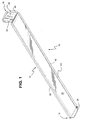
- FIGURE 1 shows a first embodiment of the turbine seal of the present invention.
- the turbine seal is defined by an elongated turbine seal member 10 that has having a length and first and second ends 12 and 14.
- the turbine seal member includes an elongated, imperforate first portion 16 and also includes a second portion 18 lengthwise adjoining the first portion.
- the first portion 16 defines the main body of the seal member and is manually-flexible.
- the second portion 18 defines a mounting bracket of the seal member and is manually-rigid.
- manufactured it is meant that the first portion 16 can be flexed by hand by an adult person of average strength.
- manufactured it is meant that the second portion 18 cannot be flexed by hand by an adult person of average strength.
- the first portion is lengthwise disposed between the first end and the second portion, the second portion is lengthwise disposed between the first portion and the second end.
- the first portion 16 is comprised of an imperforate shim-layer assemblage 20 that has a first thickness and the second portion 18 is defined from a bent strip or plate 22 that has a second thickness.
- the second thickness is on the order of at least about five times greater than the first thickness.
- the shim-layer assemblage comprises at least one shim layer or plate of uniform thickness, and may comprise at least two superimposed, generally identical shim layers or plates.
- the assemblage has no more than four layers.
- Each shim layer is impervious to gas and comprises a metal, ceramic, and/or polymer sheet.
- the choice of materials for the shim and the choice of the thickness for a shim layer are made by the artisan to meet the sealing, flexibility, and resilience requirements of a particular seal application.
- the shim-layer has a thickness of generally between about five and twenty thousandths of an inch, for example, about ten thousandths of an inch where two shim layers are provided.
- each shim layer comprises a high-temperature, cobalt-based super-alloy, such as HS-188. It is noted that the shim layers can comprise different materials and/or have different thicknesses depending on the particular seal application.
- the first portion of the seal member is comprised of two superimposed and identical shim layers 24, 124, formed from metal.
- the first end 12 of the seal member is edge-welded. Further, to facilitate placement of the seal member, the first end 12 is chamfered as shown at 26.
- a flexible and generally imperforate shim-layer assemblage 20 having opposing first and second surfaces, defined in the illustrated embodiment by the top surface 28 of shim plate 24 and the bottom surface 30 of shim plate 124, respectively.
- the shim-layer assemblage further includes to raised edges 32, 132.
- one raised edge 32 is formed entirely from one of the edges of one metal shim sheet 24, and the other raised edge 132 is formed entirely from one of the edges of another metal shim sheet 124.
- Each of the raised edges extends a generally identical distance above the first surface 28, and each of the raised edges extends generally that same identical distance below the second surface 30.
- the directions “above” and “below” are relative directions applying to the seal as viewed in FIGURES 1 and 3.
- the raised edges 32, 132 are generally mirror images of each other.
- the shim-layer assemblage is an elongated metal strip assemblage having a centerline running midway between the raised edges and having a cross section (shown in FIGURE 3) generally perpendicular to the centerline.
- each of the raised edges has a first portion 34, 134 disposed at the previously-defined generally identical distance above the first surface 28 of the metal sheet assemblage
- each of the raised edges has a second portion 36, 136 disposed at the previously-defined generally identical distance below the second surface 30.
- the first portion has a curved shape.
- the raised edges each terminate proximate the second portion 36, 136.
- each of the raised edges has a connecting portion 38, 138 joining together the first and second portions.
- the connecting portions 38, 138 have a curved shape, more specifically a generally bowed shape, pointing away from each other as illustrated in FIGURE 3. Such curved bowed shape facilitates seal installation in many seal applications, as described in greater detail below.
- each sheet metal member is stamped or rolled to form the curved raised edges. It is noted that seal can be made by pressing seal between two pressing plates (not shown).
- the seal member further includes a cloth layer assemblage 40.
- the cloth layer assemblage 40 has a thickness generally the same as or slightly greater than (e.g. by the thickness of one of the metal sheets or shims comprising the shim-layer assemblage) the previously defined identical distance (i.e., the identical distance the first and second raised edges extend above the first surface).
- the cloth layer assemblage 40 is superimposed on the second surface between the raised edges.
- the cloth layer assemblage comprises at least one cloth layer, only one of which is shown in FIGURE 3.
- Each cloth layer comprises metal, ceramic, and/or polymer fibers that have been woven, knitted, or pressed into a layer of fabric.
- each cloth layer is a woven cloth layer comprising L605 or Haynes-25.
- An exemplary cloth layer is a twilled metal cloth layer.
- twilled is meant a cloth having a twill weave (such as a twill weave which floats weft threads over two warp threads and which staggers these floats regularly).
- the cloth layer has 30 warp wires per inch and 250 weft wires per inch with each warp and weft wire having a thickness of 7-10 mils and with the cloth layer having an overall thickness of about 0.052 inch.
- An exemplary cloth-layer assemblage is a Dutch Twill weave cloth assemblage comprising a high-temperature, cobalt-based super-alloy, such as L-605. It is noted that a Dutch Twill weave will allow a small controlled leakage which provides cooling, as can be appreciated by the artisan.
- the cloth layer assemblage 40 is superimposed on generally the entire second surface 30.
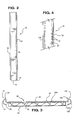
- the cloth layer assemblage 40 and the metal shim-layer assemblage 20 are attached together by a plurality of spot welds 42 (as shown in FIGURE 4).
- spot welds 42 as shown in FIGURE 4
- seam welds are used in place of spot welds.
- the first portion 16 of the turbine seal member is defined by its corresponding sections of the shim-layer and cloth-layer assemblages.
- the second portion 18 of the turbine seal member 10 includes a base portion 44 lengthwise overlapping the corresponding section of the cloth-layer assemblage 40 of the first portion and attached (such as by spot welding 46) to the corresponding sections of the cloth-layer and shim-layer assemblages.
- the second portion 18 of the turbine seal member 10 which may be made of stainless steel, includes a generally right-angle bend 48 to define mounting bracket 22 having a support portion 50 adjoining the base portion 44.
- FIGURES 7 and 8 schematically show a first embodiment of the gas-path leakage seal of the present invention.
- the gas-path leakage seal is for generally sealing a gas-path leakage-gap between spaced-apart first and second members of a gas turbine (only a small portion of which is shown in FIGURE 7).
- the turbine assembly includes a first turbine member 52, a second turbine member 54 which is proximate and circumferentially spaced apart from the first turbine member so as to define a fluid-path leakage gap 56 therebetween, and a turbine seal 10 embodying the invention.
- the first turbine member 52 has a first surface groove or slot 58
- the second turbine member has a second surface groove or slot 60 facing and generally aligned with the first surface groove 58.
- a fluid-path leakage gap as used herein includes, without limitation, a steam-path leakage gap of a turbine of a steam turbine, a compressed-air leakage gap of a compressor of a gas turbine, and a combustion-gas leakage gap in or downstream of a combustor of a gas turbine.
- downstream of the combustor includes the transition pieces, first-stage nozzle and turbine sections.
- the turbine seal 10 is identical to the previously-described turbine seal shown in FIGURES 1-6.
- the gas-path leakage seal member is disposed in the gap to extend partially in the first groove and partially in the second groove with one of the raised edges disposed entirely within the first groove and the other of the raised edges disposed entirely within the second groove.
- the gas-path leakage-gap has a higher-pressure end and a lower-pressure end. This pressure differential seats the seal such that the raised edges can resiliently and unattachedly contact the first and second members respectively along the lower pressure side of the respective first and second slots and such that the second cloth layer assemblage can also unattachedly contact the first and second members and along the lower pressure side of the first and second slots.
- the resilient contact of the metal sheet assemblage maintains sealing in the "plane" of the seal while allowing for different surface shapes, assembly misalignment, vibration, and/or thermally-induced relative movement between the first and second members.
- the way in which the seal assembly is inserted with respect to the turbine members is controlled so that the cloth layer 40 may only be provided on one side of the seal strip, as illustrated. Specifically, the cloth is provided on the downstream, pressure side of the junction.
- the cloth layer assemblage is pushed by the differential pressure into contact with the first and second members (as shown in FIGURE 8).
- the cloth layer assemblage protects the metal sheet assemblage 20 against wear.
- the installed seal is not welded or otherwise attached to the first and/or second members allowing for ease of installation.
- the turbine spline seal is vibrationally excited within a range of vibrational frequencies by motion of generally only the first and second turbine members 52, 54.
- the turbine spline seal is devoid of any resonant frequency within the range of vibrational frequencies, as is within the skill of the artisan to design by choosing, for example, an appropriate thickness and length of the mounting bracket 22.
- the turbine assembly also includes a third turbine member 62, and the mounting bracket 22 is secured to the third turbine member 62.
- the turbine assembly is a power-system gas turbine assembly
- the first and second turbine members 52, 54 are circumferentially-adjacent transition pieces of the gas turbine assembly
- the third turbine member 62 is a first stage nozzle of the gas turbine assembly.
- the installed turbine seal member 10 is radially aligned, with the mounting bracket 22 located at its radially-outer end, and a mounting block 64 is used to secure the mounting bracket 35 to the third turbine member 62.
- the mounting block has a bolt hole 66 and the third turbine member has a threaded bolt hole (not shown).
- a bolt 68 passes through the bolt hole in the mounting block and threadably-engages the threaded bolt hole of the third turbine member.
- Mounting block 64 also has a first slot 70 and a second slot 72.
- the right-angle bend 48 of the second portion 18 engages the lower of the two slots.
- the first slot 70 is the lower slot in FIGURE 7.
- the mounting block 64 may be rotated one half turn about bolt 66. As rotated, the second slot 72 will become the lower slot for engagement with the right-angle bend 48 of the second portion 18 of the turbine seal member 10.
- the manually-flexible first portion 16 of the turbine seal member 10 allows all transition-piece turbine spline seals in a standard power-system gas turbine to be replaced in generally half a day instead of the several days required for prior-art seals. It has been found that some prior-art seals had a dominant resonant frequency which was excited by the vibration (including twisting) motion of the transition pieces leading to early seal failure.
- the manually-rigid second portion 18 of the turbine seal member of the turbine seal 10 has its length and thickness chosen, as can be appreciated by those skilled in the art, to avoid the installed turbine seal from having any resonant frequencies which can be excited by the vibrational motion (typically between 80 and 200 Hertz) of the transition pieces during operation of the turbine.
Landscapes
- Engineering & Computer Science (AREA)
- Mechanical Engineering (AREA)
- General Engineering & Computer Science (AREA)
- Turbine Rotor Nozzle Sealing (AREA)
- Gasket Seals (AREA)
Abstract
Description
- The present invention relates generally to seals, and more particularly to a spline seal for a turbine.
- Turbines include gas and steam turbines. Gas turbines include, but are not limited to, gas turbine power generation equipment and gas turbine aircraft engines.
- A gas turbine has a gas path which typically includes, in serial-flow relationship, an air intake (or inlet), a compressor, a combustor, a turbine, and a gas outlet (or exhaust nozzle). Gas-path leakage occurs through gaps between gas turbine subassemblies such as through gaps between the combustor and the turbine, and gas-path leakage occurs through gaps between the components that make up a gas turbine subassembly, such as through gaps between combustor casing segments. Such components and subassemblies have surfaces of different shapes, suffer from assembly misalignment, and undergo vibration. Hot-section components thermally experience hot gas flow and typically undergo different thermal growths.
- Gas leakage, either out of the gas path or into the gas path, from an area of higher pressure to an area of lower pressure, is generally undesirable. For example, gas-path leakage in the turbine or compressor area of a gas turbine, between the rotor of the turbine or compressor and the circumferentially surrounding turbine or compressor casing, will lower the efficiency of the gas turbine leading to increased fuel costs. Additionally, gas-path leakage in the combustor area of a gas turbine will require an increase in burn temperature to maintain power level, such increased burn temperature leading to increased pollution, such as increased NOx and CO production.
- Steam turbines (which can be considered a special type of gas turbine) include, but are not limited to, steam turbine power generation equipment. A steam turbine includes a steam inlet, a turbine, and a steam outlet, wherein steam is the gas which turns the turbine rotor. The turbine of a steam turbine is similar to the turbine of a gas turbine and suffers from steam-path leakage the way the turbine of a gas turbine suffers from gas-path leakage.
- Seals are used to minimize leakage of fluids. A known fluid-path leakage seal is a cloth seal having a generally impervious and uniformly-thick shim assemblage and a cloth assemblage generally surrounding the shim assemblage. Cloth seals may be used in many applications including, but not limited to, seal assemblies for steam turbines and gas turbines used for power generation and seal assemblies for gas turbines used for aircraft and marine propulsion.
- Commonly owned U.S. Patent Number 5,934,687 relates to a cloth seal that incorporates a metal sheet having raised edges that are pushed against the associated turbine members to provide improved sealing. However, no provision is made for facilitating the quick assembly of the seal to the turbine members, and thus the metal sheet component design limits functional, manufacturing, and assembly options.
- Another fluid-path leakage seal for sealing the gap between two circumferentially-adjacent (and non-rotating) transition pieces of a power-system gas turbine is disclosed in commonly owned U.S. Patent Number 6,162,014. This seal is a manually-flexible metal seal that has a uniform thickness in the general shape of an elongated rectangular metal sheet, and has a fiber-fabric cloth layer wrapped around the metal sheet. One elongated edge of the metal bar is engaged in a surface groove of one transition piece. The other elongated edge of the metal bar is engaged in a matching and aligned surface groove of the other transition piece. One end of the metal bar serves as a mounting bracket, having a right-angle bend, which is used to secure the seal to a (non-rotating) first-stage nozzle. The grooves of transition pieces are not perfectly machined, and the grooves of transition pieces installed in power-system gas turbines are not perfectly aligned. As a result, in spite of the flexibility of the metal seal an effective seal may not be achieved between the transition pieces. In addition, the metal sheet component design limits functional, manufacturing and assembly options.
- What is needed is an leakage seal for a turbine that improves upon the seals of the '687 and '014 seal configurations so as to be easy to assemble and install, and so as to provide a more effective seal between components that are not perfectly aligned, and that increases functional, manufacturing and assembly options.
- The gas-path leakage seal according to an embodiment of the invention is for generally sealing a gas-path leakage-gap between spaced-apart first and second members of a turbine.
- In one aspect, the turbine seal of the present invention includes an elongated seal member having a length and having opposing first and second ends bounding said length, an elongated, imperforate, and flexible first portion, and a rigid second portion lengthwise adjoining said first portion, wherein said first portion is lengthwise disposed between said first end and said second portion, wherein said second portion is lengthwise disposed between said first portion and said second end, wherein said flexible first portion includes a shim-layer assemblage having opposing first and second surfaces and having two longitudinally extending raised edge regions, wherein each of said raised edge regions extends a generally identical distance above said first surface and each of said raised edge regions extends generally said identical distance below said second surface; and wherein said flexible first portion further includes a cloth layer assemblage having a thickness generally equal to or slightly greater than said identical distance and superimposed on said second surface between said raised edge regions, and wherein said second portion defines a mounting bracket.
- In an exemplary embodiment, the cloth layer assemblage and the shim-layer assemblage are attached together by spot welds, and the raised edges have curved portions.
- In another aspect of the invention, a turbine assembly is provided that includes a) a first turbine member having a first surface groove; b) a second turbine member proximate and spaced apart from said first turbine member so as to define a fluid-path leakage gap therebetween, said second turbine member having a second surface groove facing and generally aligned with said first surface groove; and c) a turbine seal including an elongated turbine seal member having a length and having opposing first and second ends bounding said length, an elongated, imperforate, and flexible first portion, and a rigid second portion lengthwise adjoining said first portion, wherein said first portion is lengthwise disposed between said first end and said second portion, wherein said second portion is lengthwise disposed between said first portion and said second end, wherein said flexible first portion includes a shim-layer assemblage having opposing first and second surfaces and having two longitudinally extending raised edge regions, wherein each of said raised edge regions extends a generally identical distance above said first surface and each of said raised edge regions extends generally said identical distance below said second surface; and wherein said flexible first portion further includes a cloth layer assemblage having a thickness generally equal to or slightly greater than said identical distance and superimposed on said second surface between said raised edge regions, wherein said second portion defines a mounting bracket, and wherein said turbine seal member is disposed in said gap with said first edge engaged in said first surface groove and with said second edge engaged in said second surface groove.
- Advantageously, in one embodiment, the turbine seal is vibrationally excited within a range of vibrational frequencies by motion of generally only the first and second turbine members during operation of the turbine, and the turbine seal is devoid of any resonant frequency within the range of vibrational frequencies.
- In an exemplary application, the turbine assembly is a power-system gas turbine assembly, the first and second turbine members are circumferentially-adjacent transition pieces, and the mounting bracket is secured to a third turbine member comprising a first stage nozzle.
- Several benefits and advantages are derived from the invention. The manually-flexible main body of the turbine seal member allows all transition-piece turbine spline seals in a standard power-system gas turbine to be replaced in generally half a day instead of the several days required for prior-art seals. Furthermore, manually flexible main body, which may be a metal sheet, provides good sealing of gas flow as the raised edges are pushed against the first and second turbine members by gas from the higher-pressure side of the seal. The first cloth layer provides some sealing and good wear resistance. The flexible metal sheet and the inherent flexibility of the cloth layer provides good seal flexibility which means the seal is very compliant and can accommodate surfaces of different shapes, assembly misalignment, vibration, and differential thermal growth. The spot welds make it easier to assemble the seal, and the curved portions make it easier to install the seal.
- The invention will now be described in greater detail, by way of example, with reference to the drawings, in which:-
- FIGURE 1 is a perspective view of a first embodiment of the turbine seal of the present invention;
- FIGURE 2 is a top plan view of a seal strip embodying the invention;
- FIGURE 3 is a cross-sectional view taken along line 3-3 of FIGURE 2;
- FIGURE 4 is a fragmentary view of the seal assembly of FIGURE 1 illustrating an exemplary welding pattern;
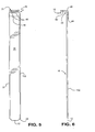
- FIGURE 5 is a top plan view of the seal assembly of FIGURE 1;
- FIGURE 6 is a side elevational view of the assembly of FIGURE 5;
- FIGURE 7 is a view of a section of a turbine including a seal assembly embodying the invention; and
- FIGURE 8 is a cross-sectional view taken along line 8-8 of FIGURE 7 showing the edges of the seal assembly engaged in the surface groove of first and second turbine members in an embodiment of the invention.
-
- Referring now to the drawings, wherein like numerals represent like elements throughout, FIGURE 1 shows a first embodiment of the turbine seal of the present invention. The turbine seal is defined by an elongated
turbine seal member 10 that has having a length and first andsecond ends 12 and 14. - The turbine seal member includes an elongated, imperforate
first portion 16 and also includes asecond portion 18 lengthwise adjoining the first portion. In an exemplary embodiment, thefirst portion 16 defines the main body of the seal member and is manually-flexible. Thesecond portion 18 defines a mounting bracket of the seal member and is manually-rigid. By "manually-flexible" it is meant that thefirst portion 16 can be flexed by hand by an adult person of average strength. By "manually-rigid" it is meant that thesecond portion 18 cannot be flexed by hand by an adult person of average strength. The first portion is lengthwise disposed between the first end and the second portion, the second portion is lengthwise disposed between the first portion and the second end. - In a first embodiment, as seen in FIGURE 3, 5 and 6, the
first portion 16 is comprised of an imperforate shim-layer assemblage 20 that has a first thickness and thesecond portion 18 is defined from a bent strip orplate 22 that has a second thickness. In an exemplary embodiment, the second thickness is on the order of at least about five times greater than the first thickness. - The shim-layer assemblage comprises at least one shim layer or plate of uniform thickness, and may comprise at least two superimposed, generally identical shim layers or plates. In this exemplary embodiment, the assemblage has no more than four layers. Each shim layer is impervious to gas and comprises a metal, ceramic, and/or polymer sheet. The choice of materials for the shim and the choice of the thickness for a shim layer are made by the artisan to meet the sealing, flexibility, and resilience requirements of a particular seal application. Usually, the shim-layer has a thickness of generally between about five and twenty thousandths of an inch, for example, about ten thousandths of an inch where two shim layers are provided. In one embodiment, each shim layer comprises a high-temperature, cobalt-based super-alloy, such as HS-188. It is noted that the shim layers can comprise different materials and/or have different thicknesses depending on the particular seal application.
- In the illustrated embodiment, the first portion of the seal member is comprised of two superimposed and identical shim layers 24, 124, formed from metal. To integrate the assembly, the
first end 12 of the seal member is edge-welded. Further, to facilitate placement of the seal member, thefirst end 12 is chamfered as shown at 26. - Thus, a flexible and generally imperforate shim-
layer assemblage 20 is provided having opposing first and second surfaces, defined in the illustrated embodiment by thetop surface 28 ofshim plate 24 and thebottom surface 30 ofshim plate 124, respectively. The shim-layer assemblage further includes to raisededges edge 32 is formed entirely from one of the edges of onemetal shim sheet 24, and the other raisededge 132 is formed entirely from one of the edges of anothermetal shim sheet 124. Each of the raised edges extends a generally identical distance above thefirst surface 28, and each of the raised edges extends generally that same identical distance below thesecond surface 30. It is noted that the directions "above" and "below" are relative directions applying to the seal as viewed in FIGURES 1 and 3. In the illustrated embodiment, the raisededges - As will be understood from the discussion above, in a first exemplary embodiment, the shim-layer assemblage is an elongated metal strip assemblage having a centerline running midway between the raised edges and having a cross section (shown in FIGURE 3) generally perpendicular to the centerline. Here, each of the raised edges has a
first portion first surface 28 of the metal sheet assemblage, each of the raised edges has asecond portion second surface 30. In the previously-defined cross section the first portion has a curved shape. Also, in the previously-defined cross-section the raised edges each terminate proximate thesecond portion portion portions - The seal member further includes a
cloth layer assemblage 40. In the illustrated embodiment, thecloth layer assemblage 40 has a thickness generally the same as or slightly greater than (e.g. by the thickness of one of the metal sheets or shims comprising the shim-layer assemblage) the previously defined identical distance (i.e., the identical distance the first and second raised edges extend above the first surface). Thecloth layer assemblage 40 is superimposed on the second surface between the raised edges. The cloth layer assemblage comprises at least one cloth layer, only one of which is shown in FIGURE 3. Each cloth layer comprises metal, ceramic, and/or polymer fibers that have been woven, knitted, or pressed into a layer of fabric. The choice of layer construction (i.e., woven, knitted, or pressed), the choice of materials for the cloth, and the choice of the thickness for a layer are made by the artisan to meet the wear resistance, flexibility, and sealing requirements of a particular seal application. It is noted that such multiple cloth layers can comprise different materials, different layer construction (i.e., woven, knitted, or pressed) and/or have different thicknesses depending on the particular seal application. In this exemplary embodiment, the cloth layer assemblage has no more than two cloth layers. In one embodiment, each cloth layer is a woven cloth layer comprising L605 or Haynes-25. An exemplary cloth layer is a twilled metal cloth layer. By "twilled" is meant a cloth having a twill weave (such as a twill weave which floats weft threads over two warp threads and which staggers these floats regularly). In an exemplary construction, the cloth layer has 30 warp wires per inch and 250 weft wires per inch with each warp and weft wire having a thickness of 7-10 mils and with the cloth layer having an overall thickness of about 0.052 inch. An exemplary cloth-layer assemblage is a Dutch Twill weave cloth assemblage comprising a high-temperature, cobalt-based super-alloy, such as L-605. It is noted that a Dutch Twill weave will allow a small controlled leakage which provides cooling, as can be appreciated by the artisan. - In an exemplary embodiment, the
cloth layer assemblage 40 is superimposed on generally the entiresecond surface 30. In the illustrated construction, thecloth layer assemblage 40 and the metal shim-layer assemblage 20 are attached together by a plurality of spot welds 42 (as shown in FIGURE 4). In another exemplary construction, seam welds (not shown) are used in place of spot welds. - Thus, the
first portion 16 of the turbine seal member is defined by its corresponding sections of the shim-layer and cloth-layer assemblages. Thesecond portion 18 of theturbine seal member 10 includes abase portion 44 lengthwise overlapping the corresponding section of the cloth-layer assemblage 40 of the first portion and attached (such as by spot welding 46) to the corresponding sections of the cloth-layer and shim-layer assemblages. Thesecond portion 18 of theturbine seal member 10, which may be made of stainless steel, includes a generally right-angle bend 48 to define mountingbracket 22 having asupport portion 50 adjoining thebase portion 44. - FIGURES 7 and 8 schematically show a first embodiment of the gas-path leakage seal of the present invention. Although the invention is described in terms of a gas turbine, it is understood to be equally applicable to a steam turbine, which can be considered a special type of gas turbine. The gas-path leakage seal is for generally sealing a gas-path leakage-gap between spaced-apart first and second members of a gas turbine (only a small portion of which is shown in FIGURE 7). The turbine assembly includes a
first turbine member 52, asecond turbine member 54 which is proximate and circumferentially spaced apart from the first turbine member so as to define a fluid-path leakage gap 56 therebetween, and aturbine seal 10 embodying the invention. Thefirst turbine member 52 has a first surface groove orslot 58, and the second turbine member has a second surface groove orslot 60 facing and generally aligned with thefirst surface groove 58. A fluid-path leakage gap as used herein includes, without limitation, a steam-path leakage gap of a turbine of a steam turbine, a compressed-air leakage gap of a compressor of a gas turbine, and a combustion-gas leakage gap in or downstream of a combustor of a gas turbine. In a power-system gas turbine, downstream of the combustor includes the transition pieces, first-stage nozzle and turbine sections. - The
turbine seal 10 is identical to the previously-described turbine seal shown in FIGURES 1-6. The gas-path leakage seal member is disposed in the gap to extend partially in the first groove and partially in the second groove with one of the raised edges disposed entirely within the first groove and the other of the raised edges disposed entirely within the second groove. The gas-path leakage-gap has a higher-pressure end and a lower-pressure end. This pressure differential seats the seal such that the raised edges can resiliently and unattachedly contact the first and second members respectively along the lower pressure side of the respective first and second slots and such that the second cloth layer assemblage can also unattachedly contact the first and second members and along the lower pressure side of the first and second slots. The resilient contact of the metal sheet assemblage maintains sealing in the "plane" of the seal while allowing for different surface shapes, assembly misalignment, vibration, and/or thermally-induced relative movement between the first and second members. In an embodiment of the invention, the way in which the seal assembly is inserted with respect to the turbine members is controlled so that thecloth layer 40 may only be provided on one side of the seal strip, as illustrated. Specifically, the cloth is provided on the downstream, pressure side of the junction. Thus, the cloth layer assemblage is pushed by the differential pressure into contact with the first and second members (as shown in FIGURE 8). The cloth layer assemblage protects themetal sheet assemblage 20 against wear. The installed seal is not welded or otherwise attached to the first and/or second members allowing for ease of installation. - During operation of the turbine, the turbine spline seal is vibrationally excited within a range of vibrational frequencies by motion of generally only the first and
second turbine members bracket 22. - The turbine assembly also includes a
third turbine member 62, and the mountingbracket 22 is secured to thethird turbine member 62. In one application of the present invention, the turbine assembly is a power-system gas turbine assembly, the first andsecond turbine members third turbine member 62 is a first stage nozzle of the gas turbine assembly. Here, the installedturbine seal member 10 is radially aligned, with the mountingbracket 22 located at its radially-outer end, and a mountingblock 64 is used to secure the mounting bracket 35 to thethird turbine member 62. The mounting block has abolt hole 66 and the third turbine member has a threaded bolt hole (not shown). Abolt 68 passes through the bolt hole in the mounting block and threadably-engages the threaded bolt hole of the third turbine member. - Mounting
block 64 also has afirst slot 70 and asecond slot 72. In the illustrated embodiment, the right-angle bend 48 of thesecond portion 18 engages the lower of the two slots. It is pointed out that thefirst slot 70 is the lower slot in FIGURE 7. It is noted that the mountingblock 64 may be rotated one half turn aboutbolt 66. As rotated, thesecond slot 72 will become the lower slot for engagement with the right-angle bend 48 of thesecond portion 18 of theturbine seal member 10. - As previously mentioned, the manually-flexible
first portion 16 of theturbine seal member 10 allows all transition-piece turbine spline seals in a standard power-system gas turbine to be replaced in generally half a day instead of the several days required for prior-art seals. It has been found that some prior-art seals had a dominant resonant frequency which was excited by the vibration (including twisting) motion of the transition pieces leading to early seal failure. The manually-rigidsecond portion 18 of the turbine seal member of theturbine seal 10 has its length and thickness chosen, as can be appreciated by those skilled in the art, to avoid the installed turbine seal from having any resonant frequencies which can be excited by the vibrational motion (typically between 80 and 200 Hertz) of the transition pieces during operation of the turbine. - For the sake of good order, various aspects of the invention are set out in the following clauses:-
- 1. A turbine seal comprising an elongated seal member (10) having a
length and having opposing first and second ends (12, 14) bounding said
length, an elongated, imperforate, and flexible first portion (16), and a rigid
second portion (18) lengthwise adjoining said first portion, wherein said first
portion (16) is lengthwise disposed between said first end (12) and said
second portion (18), wherein said second portion (18) is lengthwise disposed
between said first portion (16) and said second end (14),
wherein said flexible first portion (16) includes a shim-layer assemblage (20) having opposing first and second surfaces (28, 30) and having two longitudinally extending raised edge regions (32, 132), wherein each of said raised edge regions extends a generally identical distance above said first surface (28) and each of said raised edge regions extends generally said identical distance below said second surface (30); and wherein said flexible first portion (16) further includes a cloth layer assemblage (40) having a thickness generally equal to or slightly greater than said identical distance and superimposed on said second surface (30) between said raised edge regions, and
wherein said second portion (18) defines a mounting bracket (22). - 2. The turbine seal of clause 1, wherein said shim-layer assemblage has a first thickness and includes at least first and second metal strips (24, 124), wherein said second portion has a second thickness and comprises a metal plate, and wherein said second thickness is at least five times greater than said first thickness.
- 3. The turbine seal of clause 1, wherein said second portion includes a generally right-angle bend (48), and wherein said mounting bracket is an angled mounting bracket (22).
- 4. The turbine seal of clause 1, wherein said cloth layer assemblage (40) is mechanically secured to said shim-layer assemblage (20).
- 5. The turbine seal of clause 4, wherein said cloth layer assemblage (40) is spot welded (42) to said shim-layer assemblage (20).
- 6. The turbine seal of clause 4, wherein said second portion (18) is mechanically secured to corresponding sections of said shim-layer and cloth layer assemblages (20, 40) of said first portion.
- 7. The turbine seal of clause 1, wherein said raised edge regions (32, 132) are generally mirror images of each other.
- 8. The turbine seal of clause 1, wherein each of said raised edge regions has a first portion (34, 134) disposed at said identical distance above said first surface, wherein each of said raised edge regions has a second portion (36, 136) disposed at said identical distance below said second surface, and wherein each of said raised edge regions has a connecting portion (38, 138) joining together said first and second portions, and wherein in said cross section said connecting portion has a curved shape.
- 9. A turbine assembly comprising:
- a) a first turbine member (52) having a first surface groove (58);
- b) a second turbine member (54) proximate and spaced apart from said first turbine member so as to define a fluid-path leakage gap (56) therebetween, said second turbine member having a second surface groove (60) facing and generally aligned with said first surface groove (58); and
- c) a turbine seal including an elongated turbine seal member (10) having a length and having opposing first and second ends (12, 14) bounding said length, an elongated, imperforate, and flexible first portion (16), and a rigid second portion (18) lengthwise adjoining said first portion, wherein said first portion (16) is lengthwise disposed between said first end (12) and said second portion (18), wherein said second portion (18) is lengthwise disposed between said first portion (16) and said second end (14), wherein said flexible first portion includes a shim-layer assemblage (20) having opposing first and second surfaces (28, 30) and having two longitudinally extending raised edge regions (32, 132), wherein each of said raised edge regions extends a generally identical distance above said first surface (28) and each of said raised edge regions extends generally said identical distance below said second surface (30); and wherein said flexible first portion (16) further includes a cloth layer assemblage (40) having a thickness generally equal to or slightly greater than said identical distance and superimposed on said second surface (30) between said raised edge regions,
- 10. The turbine assembly of clause 9, wherein said shim-layer assemblage (20) has a first thickness and includes at least first and second metal strips, wherein said second portion (18) has a second thickness and comprises a metal plate, and wherein said second thickness is at least five times greater than said first thickness.
- 11. The turbine assembly of clause 9, wherein said second portion (18) includes a generally right-angle bend, and wherein said mounting bracket is an angled mounting bracket (22).
- 12. The turbine assembly of clause 9, wherein said cloth layer assemblage (40) is mechanically secured to said shim-layer assemblage (20).
- 13. The turbine assembly of
clause 12, wherein said cloth layer assemblage (40) is spot welded (42) to said shim-layer assemblage (20). - 14. The turbine assembly of
clause 12, wherein said second portion (18) is mechanically secured (46) to corresponding sections of said shim-layer and cloth layer assemblages (20, 40) of said first portion (16). - 15. The turbine assembly of clause 9, also including a third turbine member (62), and wherein said mounting bracket (22) defined by said second portion is secured to said third turbine member.
- 16. The turbine assembly of clause 15, wherein said second portion includes a generally right-angle bend (48), and wherein said mounting bracket is an angled mounting bracket.
- 17. The turbine assembly of
clause 16, wherein said turbine assembly is a power-system gas turbine assembly, wherein said first and second turbine members (52, 54) are circumferentially-adjacent transition pieces of said gas turbine assembly, and wherein said third turbine member (62) is a first stage nozzle of said gas turbine assembly. - 18. The turbine assembly of
clause 16, further comprising a mounting block (64) for securing the mounting bracket (22) to the third turbine member (62),'the mounting block having a bolt hole (66) and the third turbine member having a threaded bolt hole for receiving a common bolt (68) to secure the mounting block to the third turbine member. - 19. The turbine assembly of
clause 18, wherein the mounting block (64) includes first and second slots (70, 72), the right-angle bend of the second portion engaging one of said slots to secure the seal member (10) to the third turbine member (62). - 20. The turbine assembly of clause 9, wherein each of said raised edge regions (32, 132) has a first portion (34, 134) disposed at said identical distance above said first surface, wherein each of said raised edge regions has a second portion (36, 136) disposed at said identical distance below said second surface, and wherein each of said raised edge regions has a connecting portion (38, 138) joining together said first and second portions, and wherein in said cross section said connecting portion has a curved shape.
-
wherein said second portion (18) defines a mounting bracket (22), and
wherein said turbine seal member is disposed in said gap (56) with said first edge (32) engaged in said first surface groove (58) and with said second edge (132) engaged in said second surface groove (60).
Claims (10)
- turbine seal comprising an elongated seal member (10) having a length and having opposing first and second ends (12, 14) bounding said length, an elongated, imperforate, and flexible first portion (16), and a rigid second portion (18) lengthwise adjoining said first portion, wherein said first portion (16) is lengthwise disposed between said first end (12) and said second portion (18), wherein said second portion (18) is lengthwise disposed between said first portion (16) and said second end (14),
wherein said flexible first portion (16) includes a shim-layer assemblage (20) having opposing first and second surfaces (28, 30) and having two longitudinally extending raised edge regions (32, 132), wherein each of said raised edge regions extends a generally identical distance above said first surface (28) and each of said raised edge regions extends generally said identical distance below said second surface (30); and wherein said flexible first portion (16) further includes a cloth layer assemblage (40) having a thickness generally equal to or slightly greater than said identical distance and superimposed on said second surface (30) between said raised edge regions, and
wherein said second portion (18) defines a mounting bracket (22). - The turbine seal of claim 1, wherein said shim-layer assemblage has a first thickness and includes at least first and second metal strips (24, 124), wherein said second portion has a second thickness and comprises a metal plate, and wherein said second thickness is at least five times greater than said first thickness.
- The turbine seal of claim 1, wherein said second portion includes a generally right-angle bend (48), and wherein said mounting bracket is an angled mounting bracket (22).
- The turbine seal of claim 1, wherein said cloth layer assemblage (40) is mechanically secured to said shim-layer assemblage (20).
- The turbine seal of claim 1, wherein each of said raised edge regions has a first portion (34, 134) disposed at said identical distance above said first surface, wherein each of said raised edge regions has a second portion (36, 136) disposed at said identical distance below said second surface, and wherein each of said raised edge regions has a connecting portion (38, 138) joining together said first and second portions, and wherein in said cross section said connecting portion has a curved shape.
- A turbine assembly comprising:wherein said flexible first portion includes a shim-layer assemblage (20) having opposing first and second surfaces (28, 30) and having two longitudinally extending raised edge regions (32, 132), wherein each of said raised edge regions extends a generally identical distance above said first surface (28) and each of said raised edge regions extends generally said identical distance below said second surface (30); and wherein said flexible first portion (16) further includes a cloth layer assemblage (40) having a thickness generally equal to or slightly greater than said identical distance and superimposed on said second surface (30) between said raised edge regions,a) a first turbine member (52) having a first surface groove (58);b) a second turbine member (54) proximate and spaced apart from said first turbine member so as to define a fluid-path leakage gap (56) therebetween, said second turbine member having a second surface groove (60) facing and generally aligned with said first surface groove (58); andc) a turbine seal including an elongated turbine seal member (10) having a length and having opposing first and second ends (12, 14) bounding said length, an elongated, imperforate, and flexible first portion (16), and a rigid second portion (18) lengthwise adjoining said first portion, wherein said first portion (16) is lengthwise disposed between said first end (12) and said second portion (18), wherein said second portion (18) is lengthwise disposed between said first portion (16) and said second end (14),
wherein said second portion (18) defines a mounting bracket (22), and
wherein said turbine seal member is disposed in said gap (56) with said first edge (32) engaged in said first surface groove (58) and with said second edge (132) engaged in said second surface groove (60). - The turbine assembly of claim 6, wherein said shim-layer assemblage (20) has a first thickness and includes at least first and second metal strips, wherein said second portion (18) has a second thickness and comprises a metal plate, and wherein said second thickness is at least five times greater than said first thickness.
- The turbine assembly of claim 6, wherein said cloth layer assemblage (40) is mechanically secured to said shim-layer assemblage (20).
- The turbine assembly of claim 6, also including a third turbine member (62), and wherein said mounting bracket (22) defined by said second portion is secured to said third turbine member.
- The turbine assembly of claim 6, wherein each of said raised edge regions (32, 132) has a first portion (34, 134) disposed at said identical distance above said first surface, wherein each of said raised edge regions has a second portion (36, 136) disposed at said identical distance below said second surface, and wherein each of said raised edge regions has a connecting portion (38, 138) joining together said first and second portions, and wherein in said cross section said connecting portion has a curved shape.
Applications Claiming Priority (2)
| Application Number | Priority Date | Filing Date | Title |
|---|---|---|---|
| US09/682,335 US20030039542A1 (en) | 2001-08-21 | 2001-08-21 | Transition piece side sealing element and turbine assembly containing such seal |
| US682335 | 2001-08-21 |
Publications (2)
| Publication Number | Publication Date |
|---|---|
| EP1291493A2 true EP1291493A2 (en) | 2003-03-12 |
| EP1291493A3 EP1291493A3 (en) | 2009-06-10 |
Family
ID=24739239
Family Applications (1)
| Application Number | Title | Priority Date | Filing Date |
|---|---|---|---|
| EP02255697A Withdrawn EP1291493A3 (en) | 2001-08-21 | 2002-08-13 | Transition piece side sealing element and turbine assembly containing such seal |
Country Status (3)
| Country | Link |
|---|---|
| US (1) | US20030039542A1 (en) |
| EP (1) | EP1291493A3 (en) |
| JP (1) | JP2003097220A (en) |
Cited By (9)
| Publication number | Priority date | Publication date | Assignee | Title |
|---|---|---|---|---|
| EP1785592A2 (en) * | 2005-11-10 | 2007-05-16 | General Electric Company | Sealing assembly for turbine engines |
| WO2011153393A3 (en) * | 2010-06-04 | 2012-04-26 | Siemens Energy, Inc. | Gas turbine engine sealing structure |
| CN102536338A (en) * | 2010-11-29 | 2012-07-04 | 通用电气公司 | Cloth seal for turbo-machinery |
| FR2970503A1 (en) * | 2011-01-14 | 2012-07-20 | Gen Electric | ASSEMBLY AND METHOD FOR PREVENTING THE PASSAGE OF A FLUID |
| CN103375589A (en) * | 2012-04-30 | 2013-10-30 | 通用电气公司 | Flexible seal of transition duct in turbine system |
| WO2014025733A1 (en) * | 2012-08-06 | 2014-02-13 | General Electric Company | Gas path leakage seal for a turbine |
| FR3065986A1 (en) * | 2017-05-02 | 2018-11-09 | Safran Aircraft Engines | ASSEMBLY FOR GAS TURBINE, GAS TURBINE |
| US10196913B1 (en) | 2014-12-17 | 2019-02-05 | United Technologies Corporation | Featherseal having tapered radial portion |
| EP3789638A1 (en) * | 2019-09-05 | 2021-03-10 | Siemens Aktiengesellschaft | Seal for combustion apparatus |
Families Citing this family (37)
| Publication number | Priority date | Publication date | Assignee | Title |
|---|---|---|---|---|
| GB2401658B (en) * | 2003-05-16 | 2006-07-26 | Rolls Royce Plc | Sealing arrangement |
| US7334800B2 (en) * | 2004-10-29 | 2008-02-26 | Power Systems Mfg., Llc | Seal for a gas turbine engine having improved flexibility |
| DE102005013798A1 (en) * | 2005-03-24 | 2006-09-28 | Alstom Technology Ltd. | Heat release segment for sealing a flow channel of a flow rotary machine |
| EP2048327B1 (en) * | 2007-10-08 | 2013-12-04 | Siemens Aktiengesellschaft | Sealing system for a turbomachine |
| US20100061847A1 (en) * | 2008-09-09 | 2010-03-11 | General Electric Company | Steam turbine part including ceramic matrix composite (cmc) |
| US8141879B2 (en) * | 2009-07-20 | 2012-03-27 | General Electric Company | Seals for a turbine engine, and methods of assembling a turbine engine |
| US8398090B2 (en) | 2010-06-09 | 2013-03-19 | General Electric Company | Spring loaded seal assembly for turbines |
| US8225614B2 (en) | 2010-10-07 | 2012-07-24 | General Electric Company | Shim for sealing transition pieces |
| US20120119449A1 (en) * | 2010-11-11 | 2012-05-17 | General Electric Company | Transition Piece Sealing Assembly With Seal Overlay |
| US8777202B2 (en) | 2011-05-19 | 2014-07-15 | General Electric Company | Tool for adjusting seal |
| US8978388B2 (en) * | 2011-06-03 | 2015-03-17 | General Electric Company | Load member for transition duct in turbine system |
| US9115585B2 (en) * | 2011-06-06 | 2015-08-25 | General Electric Company | Seal assembly for gas turbine |
| US8696309B2 (en) * | 2011-06-27 | 2014-04-15 | Turbine Services Ltd. | Brazed turbine seal |
| US9353635B2 (en) * | 2011-08-16 | 2016-05-31 | General Electric Company | Seal end attachment |
| US10161523B2 (en) * | 2011-12-23 | 2018-12-25 | General Electric Company | Enhanced cloth seal |
| US8845285B2 (en) * | 2012-01-10 | 2014-09-30 | General Electric Company | Gas turbine stator assembly |
| US9249678B2 (en) * | 2012-06-27 | 2016-02-02 | General Electric Company | Transition duct for a gas turbine |
| US9771895B2 (en) * | 2012-10-17 | 2017-09-26 | United Technologies Corporation | Seal assembly for liners of exhaust nozzle |
| US9316155B2 (en) | 2013-03-18 | 2016-04-19 | General Electric Company | System for providing fuel to a combustor |
| US9322556B2 (en) | 2013-03-18 | 2016-04-26 | General Electric Company | Flow sleeve assembly for a combustion module of a gas turbine combustor |
| US9316396B2 (en) | 2013-03-18 | 2016-04-19 | General Electric Company | Hot gas path duct for a combustor of a gas turbine |
| US9383104B2 (en) | 2013-03-18 | 2016-07-05 | General Electric Company | Continuous combustion liner for a combustor of a gas turbine |
| US10436445B2 (en) | 2013-03-18 | 2019-10-08 | General Electric Company | Assembly for controlling clearance between a liner and stationary nozzle within a gas turbine |
| US9400114B2 (en) | 2013-03-18 | 2016-07-26 | General Electric Company | Combustor support assembly for mounting a combustion module of a gas turbine |
| US9631812B2 (en) | 2013-03-18 | 2017-04-25 | General Electric Company | Support frame and method for assembly of a combustion module of a gas turbine |
| US9360217B2 (en) | 2013-03-18 | 2016-06-07 | General Electric Company | Flow sleeve for a combustion module of a gas turbine |
| US9416675B2 (en) * | 2014-01-27 | 2016-08-16 | General Electric Company | Sealing device for providing a seal in a turbomachine |
| US10047622B2 (en) * | 2014-07-22 | 2018-08-14 | General Electric Company | Flexible layered seal for turbomachinery |
| US9970308B2 (en) * | 2015-01-26 | 2018-05-15 | United Technologies Corporation | Feather seal |
| US11255201B2 (en) | 2016-01-27 | 2022-02-22 | Siemens Energy Global GmbH & Co. KG | Transition system side seal for gas turbine engines |
| US10890078B1 (en) | 2017-06-12 | 2021-01-12 | Technetics Group Llc | Flexible seal assembly |
| US10655489B2 (en) | 2018-01-04 | 2020-05-19 | General Electric Company | Systems and methods for assembling flow path components |
| US11248705B2 (en) * | 2018-06-19 | 2022-02-15 | General Electric Company | Curved seal with relief cuts for adjacent gas turbine components |
| US11231175B2 (en) | 2018-06-19 | 2022-01-25 | General Electric Company | Integrated combustor nozzles with continuously curved liner segments |
| US11047248B2 (en) * | 2018-06-19 | 2021-06-29 | General Electric Company | Curved seal for adjacent gas turbine components |
| US10927691B2 (en) | 2019-03-21 | 2021-02-23 | Solar Turbines Incorporated | Nozzle segment air seal |
| US11371709B2 (en) | 2020-06-30 | 2022-06-28 | General Electric Company | Combustor air flow path |
Citations (3)
| Publication number | Priority date | Publication date | Assignee | Title |
|---|---|---|---|---|
| US5868398A (en) * | 1997-05-20 | 1999-02-09 | United Technologies Corporation | Gas turbine stator vane seal |
| US5934687A (en) * | 1997-07-07 | 1999-08-10 | General Electric Company | Gas-path leakage seal for a turbine |
| US6162014A (en) * | 1998-09-22 | 2000-12-19 | General Electric Company | Turbine spline seal and turbine assembly containing such spline seal |
Family Cites Families (3)
| Publication number | Priority date | Publication date | Assignee | Title |
|---|---|---|---|---|
| US5125796A (en) * | 1991-05-14 | 1992-06-30 | General Electric Company | Transition piece seal spring for a gas turbine |
| US6193240B1 (en) * | 1999-01-11 | 2001-02-27 | General Electric Company | Seal assembly |
| US6431825B1 (en) * | 2000-07-28 | 2002-08-13 | Alstom (Switzerland) Ltd | Seal between static turbine parts |
-
2001
- 2001-08-21 US US09/682,335 patent/US20030039542A1/en not_active Abandoned
-
2002
- 2002-08-13 EP EP02255697A patent/EP1291493A3/en not_active Withdrawn
- 2002-08-21 JP JP2002239987A patent/JP2003097220A/en active Pending
Patent Citations (3)
| Publication number | Priority date | Publication date | Assignee | Title |
|---|---|---|---|---|
| US5868398A (en) * | 1997-05-20 | 1999-02-09 | United Technologies Corporation | Gas turbine stator vane seal |
| US5934687A (en) * | 1997-07-07 | 1999-08-10 | General Electric Company | Gas-path leakage seal for a turbine |
| US6162014A (en) * | 1998-09-22 | 2000-12-19 | General Electric Company | Turbine spline seal and turbine assembly containing such spline seal |
Cited By (16)
| Publication number | Priority date | Publication date | Assignee | Title |
|---|---|---|---|---|
| EP1785592A3 (en) * | 2005-11-10 | 2012-08-01 | General Electric Company | Sealing assembly for turbine engines |
| EP1785592A2 (en) * | 2005-11-10 | 2007-05-16 | General Electric Company | Sealing assembly for turbine engines |
| US8821114B2 (en) | 2010-06-04 | 2014-09-02 | Siemens Energy, Inc. | Gas turbine engine sealing structure |
| WO2011153393A3 (en) * | 2010-06-04 | 2012-04-26 | Siemens Energy, Inc. | Gas turbine engine sealing structure |
| CN102536338A (en) * | 2010-11-29 | 2012-07-04 | 通用电气公司 | Cloth seal for turbo-machinery |
| CN102536338B (en) * | 2010-11-29 | 2015-12-16 | 通用电气公司 | For the cloth seal of turbo machine |
| FR2970503A1 (en) * | 2011-01-14 | 2012-07-20 | Gen Electric | ASSEMBLY AND METHOD FOR PREVENTING THE PASSAGE OF A FLUID |
| EP2660428A1 (en) * | 2012-04-30 | 2013-11-06 | General Electric Company | Turbine system comprising a transition duct with a flexible seal |
| CN103375589A (en) * | 2012-04-30 | 2013-10-30 | 通用电气公司 | Flexible seal of transition duct in turbine system |
| WO2014025733A1 (en) * | 2012-08-06 | 2014-02-13 | General Electric Company | Gas path leakage seal for a turbine |
| US10196913B1 (en) | 2014-12-17 | 2019-02-05 | United Technologies Corporation | Featherseal having tapered radial portion |
| FR3065986A1 (en) * | 2017-05-02 | 2018-11-09 | Safran Aircraft Engines | ASSEMBLY FOR GAS TURBINE, GAS TURBINE |
| US10760440B2 (en) | 2017-05-02 | 2020-09-01 | Safran Aircraft Engines | Assembly for gas turbine, associated gas turbine |
| EP3789638A1 (en) * | 2019-09-05 | 2021-03-10 | Siemens Aktiengesellschaft | Seal for combustion apparatus |
| WO2021043527A1 (en) * | 2019-09-05 | 2021-03-11 | Siemens Energy Global GmbH & Co. KG | Seal for combustion apparatus |
| US11746667B2 (en) | 2019-09-05 | 2023-09-05 | Siemens Energy Global GmbH & Co. KG | Seal for combustion apparatus |
Also Published As
| Publication number | Publication date |
|---|---|
| JP2003097220A (en) | 2003-04-03 |
| EP1291493A3 (en) | 2009-06-10 |
| US20030039542A1 (en) | 2003-02-27 |
Similar Documents
| Publication | Publication Date | Title |
|---|---|---|
| EP1291493A2 (en) | Transition piece side sealing element and turbine assembly containing such seal | |
| US5934687A (en) | Gas-path leakage seal for a turbine | |
| US6162014A (en) | Turbine spline seal and turbine assembly containing such spline seal | |
| EP0903519B1 (en) | Flexible cloth seal assembly | |
| EP1239118B1 (en) | Flexible cloth seal for turbine combustors | |
| EP1537297B1 (en) | Biased wear resistant turbine seal assembly | |
| EP1832716B1 (en) | Segmented component seal | |
| JP4672728B2 (en) | Gas turbine combustor seal structure | |
| US5657998A (en) | Gas-path leakage seal for a gas turbine | |
| US7901186B2 (en) | Seal assembly | |
| US20130181413A1 (en) | Spring loaded seal assembly for turbines | |
| EP2977561B1 (en) | Flexible layered seal for turbomachinery | |
| US9188228B2 (en) | Layered seal for turbomachinery | |
| EP2247830B1 (en) | Flexible seal for a turbine and corresponding turbine | |
| JP2003113945A (en) | Shaft sealing mechanism and turbine | |
| US20120085103A1 (en) | Shim for sealing transition pieces | |
| US20160032747A1 (en) | Sealing element for sealing gap | |
| US20140062032A1 (en) | Spring-loaded seal assembly | |
| US20140062034A1 (en) | Gas path leakage seal for a turbine | |
| Wolfe et al. | Gas-path leakage seal for a gas turbine | |
| CZ248799A3 (en) | Turbine seal and turbine assembly containing such seal |
Legal Events
| Date | Code | Title | Description |
|---|---|---|---|
| PUAI | Public reference made under article 153(3) epc to a published international application that has entered the european phase |
Free format text: ORIGINAL CODE: 0009012 |
|
| AK | Designated contracting states |
Kind code of ref document: A2 Designated state(s): AT BE BG CH CY CZ DE DK EE ES FI FR GB GR IE IT LI LU MC NL PT SE SK TR Designated state(s): AT BE BG CH CY CZ DE DK EE ES FI FR GB GR IE IT LI LU MC NL PT SE SK TR |
|
| AX | Request for extension of the european patent |
Extension state: AL LT LV MK RO SI |
|
| PUAL | Search report despatched |
Free format text: ORIGINAL CODE: 0009013 |
|
| AK | Designated contracting states |
Kind code of ref document: A3 Designated state(s): AT BE BG CH CY CZ DE DK EE ES FI FR GB GR IE IT LI LU MC NL PT SE SK TR |
|
| AX | Request for extension of the european patent |
Extension state: AL LT LV MK RO SI |
|
| AKX | Designation fees paid | ||
| REG | Reference to a national code |
Ref country code: DE Ref legal event code: 8566 |
|
| STAA | Information on the status of an ep patent application or granted ep patent |
Free format text: STATUS: THE APPLICATION IS DEEMED TO BE WITHDRAWN |
|
| 18D | Application deemed to be withdrawn |
Effective date: 20091211 |