EP1291243A2 - An image pickup apparatus for a surrounding area of a vehicle - Google Patents
An image pickup apparatus for a surrounding area of a vehicle Download PDFInfo
- Publication number
- EP1291243A2 EP1291243A2 EP02254198A EP02254198A EP1291243A2 EP 1291243 A2 EP1291243 A2 EP 1291243A2 EP 02254198 A EP02254198 A EP 02254198A EP 02254198 A EP02254198 A EP 02254198A EP 1291243 A2 EP1291243 A2 EP 1291243A2
- Authority
- EP
- European Patent Office
- Prior art keywords
- infrared light
- image pickup
- infrared
- pickup apparatus
- vehicle
- Prior art date
- Legal status (The legal status is an assumption and is not a legal conclusion. Google has not performed a legal analysis and makes no representation as to the accuracy of the status listed.)
- Withdrawn
Links
- 230000001678 irradiating effect Effects 0.000 claims abstract description 12
- 230000001934 delay Effects 0.000 claims 2
- 230000003111 delayed effect Effects 0.000 description 3
- 238000000034 method Methods 0.000 description 3
- 230000004044 response Effects 0.000 description 3
- 239000002699 waste material Substances 0.000 description 3
- 238000001514 detection method Methods 0.000 description 2
- 238000010586 diagram Methods 0.000 description 2
- 241001465754 Metazoa Species 0.000 description 1
- 230000005611 electricity Effects 0.000 description 1
Images


Classifications
-
- B—PERFORMING OPERATIONS; TRANSPORTING
- B60—VEHICLES IN GENERAL
- B60Q—ARRANGEMENT OF SIGNALLING OR LIGHTING DEVICES, THE MOUNTING OR SUPPORTING THEREOF OR CIRCUITS THEREFOR, FOR VEHICLES IN GENERAL
- B60Q1/00—Arrangement of optical signalling or lighting devices, the mounting or supporting thereof or circuits therefor
- B60Q1/26—Arrangement of optical signalling or lighting devices, the mounting or supporting thereof or circuits therefor the devices being primarily intended to indicate the vehicle, or parts thereof, or to give signals, to other traffic
- B60Q1/2661—Arrangement of optical signalling or lighting devices, the mounting or supporting thereof or circuits therefor the devices being primarily intended to indicate the vehicle, or parts thereof, or to give signals, to other traffic mounted on parts having other functions
- B60Q1/2665—Arrangement of optical signalling or lighting devices, the mounting or supporting thereof or circuits therefor the devices being primarily intended to indicate the vehicle, or parts thereof, or to give signals, to other traffic mounted on parts having other functions on rear-view mirrors
-
- B—PERFORMING OPERATIONS; TRANSPORTING
- B60—VEHICLES IN GENERAL
- B60R—VEHICLES, VEHICLE FITTINGS, OR VEHICLE PARTS, NOT OTHERWISE PROVIDED FOR
- B60R1/00—Optical viewing arrangements; Real-time viewing arrangements for drivers or passengers using optical image capturing systems, e.g. cameras or video systems specially adapted for use in or on vehicles
- B60R1/20—Real-time viewing arrangements for drivers or passengers using optical image capturing systems, e.g. cameras or video systems specially adapted for use in or on vehicles
- B60R1/22—Real-time viewing arrangements for drivers or passengers using optical image capturing systems, e.g. cameras or video systems specially adapted for use in or on vehicles for viewing an area outside the vehicle, e.g. the exterior of the vehicle
-
- B—PERFORMING OPERATIONS; TRANSPORTING
- B60—VEHICLES IN GENERAL
- B60R—VEHICLES, VEHICLE FITTINGS, OR VEHICLE PARTS, NOT OTHERWISE PROVIDED FOR
- B60R1/00—Optical viewing arrangements; Real-time viewing arrangements for drivers or passengers using optical image capturing systems, e.g. cameras or video systems specially adapted for use in or on vehicles
- B60R1/20—Real-time viewing arrangements for drivers or passengers using optical image capturing systems, e.g. cameras or video systems specially adapted for use in or on vehicles
- B60R1/30—Real-time viewing arrangements for drivers or passengers using optical image capturing systems, e.g. cameras or video systems specially adapted for use in or on vehicles providing vision in the non-visible spectrum, e.g. night or infrared vision
-
- H—ELECTRICITY
- H04—ELECTRIC COMMUNICATION TECHNIQUE
- H04N—PICTORIAL COMMUNICATION, e.g. TELEVISION
- H04N23/00—Cameras or camera modules comprising electronic image sensors; Control thereof
- H04N23/56—Cameras or camera modules comprising electronic image sensors; Control thereof provided with illuminating means
-
- H—ELECTRICITY
- H04—ELECTRIC COMMUNICATION TECHNIQUE
- H04N—PICTORIAL COMMUNICATION, e.g. TELEVISION
- H04N7/00—Television systems
- H04N7/18—Closed-circuit television [CCTV] systems, i.e. systems in which the video signal is not broadcast
- H04N7/183—Closed-circuit television [CCTV] systems, i.e. systems in which the video signal is not broadcast for receiving images from a single remote source
-
- B—PERFORMING OPERATIONS; TRANSPORTING
- B60—VEHICLES IN GENERAL
- B60R—VEHICLES, VEHICLE FITTINGS, OR VEHICLE PARTS, NOT OTHERWISE PROVIDED FOR
- B60R2300/00—Details of viewing arrangements using cameras and displays, specially adapted for use in a vehicle
- B60R2300/10—Details of viewing arrangements using cameras and displays, specially adapted for use in a vehicle characterised by the type of camera system used
- B60R2300/101—Details of viewing arrangements using cameras and displays, specially adapted for use in a vehicle characterised by the type of camera system used using cameras with adjustable capturing direction
-
- B—PERFORMING OPERATIONS; TRANSPORTING
- B60—VEHICLES IN GENERAL
- B60R—VEHICLES, VEHICLE FITTINGS, OR VEHICLE PARTS, NOT OTHERWISE PROVIDED FOR
- B60R2300/00—Details of viewing arrangements using cameras and displays, specially adapted for use in a vehicle
- B60R2300/10—Details of viewing arrangements using cameras and displays, specially adapted for use in a vehicle characterised by the type of camera system used
- B60R2300/103—Details of viewing arrangements using cameras and displays, specially adapted for use in a vehicle characterised by the type of camera system used using camera systems provided with artificial illumination device, e.g. IR light source
-
- B—PERFORMING OPERATIONS; TRANSPORTING
- B60—VEHICLES IN GENERAL
- B60R—VEHICLES, VEHICLE FITTINGS, OR VEHICLE PARTS, NOT OTHERWISE PROVIDED FOR
- B60R2300/00—Details of viewing arrangements using cameras and displays, specially adapted for use in a vehicle
- B60R2300/10—Details of viewing arrangements using cameras and displays, specially adapted for use in a vehicle characterised by the type of camera system used
- B60R2300/106—Details of viewing arrangements using cameras and displays, specially adapted for use in a vehicle characterised by the type of camera system used using night vision cameras
-
- B—PERFORMING OPERATIONS; TRANSPORTING
- B60—VEHICLES IN GENERAL
- B60R—VEHICLES, VEHICLE FITTINGS, OR VEHICLE PARTS, NOT OTHERWISE PROVIDED FOR
- B60R2300/00—Details of viewing arrangements using cameras and displays, specially adapted for use in a vehicle
- B60R2300/20—Details of viewing arrangements using cameras and displays, specially adapted for use in a vehicle characterised by the type of display used
- B60R2300/205—Details of viewing arrangements using cameras and displays, specially adapted for use in a vehicle characterised by the type of display used using a head-up display
-
- B—PERFORMING OPERATIONS; TRANSPORTING
- B60—VEHICLES IN GENERAL
- B60R—VEHICLES, VEHICLE FITTINGS, OR VEHICLE PARTS, NOT OTHERWISE PROVIDED FOR
- B60R2300/00—Details of viewing arrangements using cameras and displays, specially adapted for use in a vehicle
- B60R2300/30—Details of viewing arrangements using cameras and displays, specially adapted for use in a vehicle characterised by the type of image processing
-
- B—PERFORMING OPERATIONS; TRANSPORTING
- B60—VEHICLES IN GENERAL
- B60R—VEHICLES, VEHICLE FITTINGS, OR VEHICLE PARTS, NOT OTHERWISE PROVIDED FOR
- B60R2300/00—Details of viewing arrangements using cameras and displays, specially adapted for use in a vehicle
- B60R2300/80—Details of viewing arrangements using cameras and displays, specially adapted for use in a vehicle characterised by the intended use of the viewing arrangement
- B60R2300/8053—Details of viewing arrangements using cameras and displays, specially adapted for use in a vehicle characterised by the intended use of the viewing arrangement for bad weather conditions or night vision
-
- B—PERFORMING OPERATIONS; TRANSPORTING
- B60—VEHICLES IN GENERAL
- B60R—VEHICLES, VEHICLE FITTINGS, OR VEHICLE PARTS, NOT OTHERWISE PROVIDED FOR
- B60R2300/00—Details of viewing arrangements using cameras and displays, specially adapted for use in a vehicle
- B60R2300/80—Details of viewing arrangements using cameras and displays, specially adapted for use in a vehicle characterised by the intended use of the viewing arrangement
- B60R2300/8093—Details of viewing arrangements using cameras and displays, specially adapted for use in a vehicle characterised by the intended use of the viewing arrangement for obstacle warning
-
- H—ELECTRICITY
- H04—ELECTRIC COMMUNICATION TECHNIQUE
- H04N—PICTORIAL COMMUNICATION, e.g. TELEVISION
- H04N5/00—Details of television systems
- H04N5/30—Transforming light or analogous information into electric information
- H04N5/33—Transforming infrared radiation
Definitions
- a headlight for securing the visibility of a driver is provided for achieving the safe driving.
- just use of the headlight is not enough to secure the visibility for achieving the safe driving
- An image pickup apparatus using an infrared light has been developed for supplying the better visibility to a driver driving a vehicle at night, etc.
- the image pickup apparatus there has been developed the technique, in which the infrared camera is adopted, for achieving the certain image pickup of obstacles existing in the surrounding area.
- the image pickup of obstacle is achieved by detecting the reflected infrared light, which is irradiated from the infrared light emitter and is reflected by the obstacles.
- the same image pickup apparatus may be equipped in the oncoming vehicle.
- infrared light is irradiated from the oncoming vehicle and is received by the infrared camera equipped in the vehicle, the image obtained by the infrared camera equipped in the vehicle on driving is engulfed in a uniformly white glow.
- whiteout phenomenon This phenomenon is known as "whiteout phenomenon”.
- the present invention relates to an image pickup apparatus, which is equipped in a vehicle and is used for obtaining an image of the surrounding area by performing the image pickup.
- This image pickup apparatus has an infrared light emitter for irradiating an infrared light towards the surrounding area of the vehicle, an infrared camera capable of performing the image pickup by receiving the reflected infrared light, and an infrared light sensor for detecting a pulse light of infrared region from near-infrared region to be irradiated form oncoming vehicle.
- the obstacle is presenting in the area covered with the infrared light emitted from the infrared light emitter, since the reflected infrared light, which is irradiated from the infrared light emitter and is reflected by the obstacles, is recorded by the infrared camera, a driver of the vehicle can recognize existence of the obstacle.
- the infrared light emitting apparatus and the infrared camera are provided at the inner mirror of the vehicle.
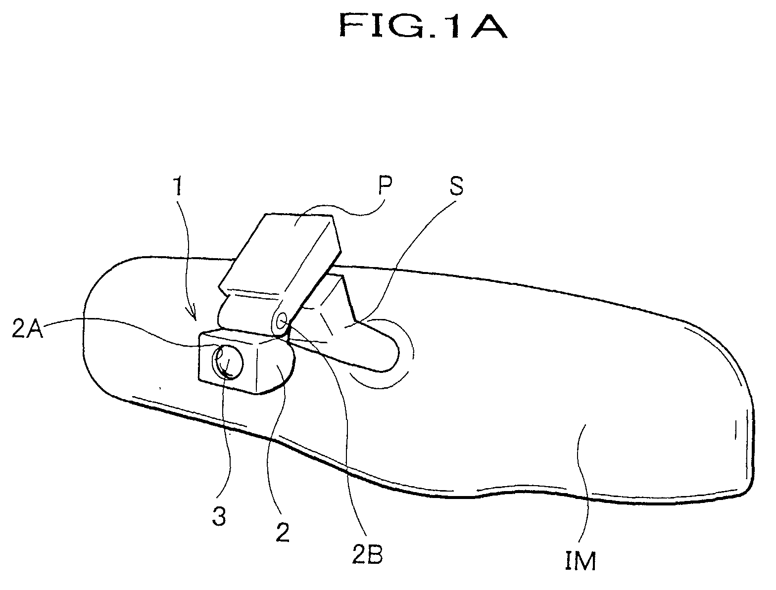
- FIG. 1A is a perspective view showing the surroundings of an image pickup apparatus of a vehicle.
- FIG. 1B is a side sectional view of an image pickup apparatus.
- FIG. 2 is a block diagram of an image pickup apparatus.
- an image pickup apparatus is attached to a fixing part P, to which a stay S of an inner mirror IM is engaged.
- the inner mirror IM is attached to a windshield F through the stay S, and the orientation thereof is adjusted by shifting the stay S in compliance with the differences of a driver's body for securing the rear-side visibility of a driver.
- the orientation of the image pickup apparatus 1 is constructed so as not to be changed for keeping the irradiating direction even if the orientation of the inner mirror IM is adjusted for facing the suitable direction. To be more precise, the irradiating direction of image pickup apparatus 1 is not affected by the adjustment of the inner mirror IM.
- the casing 2 is pivotably attached to the fixing part P through a hinge 2B. Thus, the adjustment of the orientation of the infrared camera 3 is allowed.
- An infrared light irradiator 4 and an infrared light sensor 5 are stored within the casing 2.
- a control unit 6 is also stored in the casing 2 together with both the infrared light irradiator 4 and the infrared light sensor 5.
- the control unit 6 is electrically connected to each of the infrared camera 3, the infrared light irradiator 4, and the infrared light sensor 5.
- the emitting part of the infrared light irradiator 4 is constituted so as to enable the irradiation of infrared light through the eyelet 1A provided on the casing 2. According to the present invention, if the obstacles is presenting in the area covered by the irradiated infrared light, the image of the obstacle is clearly picked up, and is acknowledged by a driver.
- the infrared light sensor 5 detects the infrared light incoming from the outside.
- the infrared light incoming from the outside through the eyelet 2A is received at a light receiving part of the infrared light sensor 5.
- this infrared light sensor 5 detects the light pulse irradiated form the image pickup apparatus equipped in the oncoming vehicle.
- the control unit 6 has a central processing unit (CPU), a read only memory (ROM), a memory, etc.
- the control unit 6 processes the computing based on signals outputted from the infrared camera 3 and an infrared light sensor 5, and outputs the predetermined signals, such as command signals, based on the computed result.
- the image processing apparatus 15 generates the images to be displayed on the image monitor 16 based on the image signal outputted from the infrared camera 3.
- the image monitor 16 has a projector (not shown) for displaying the image on the windshield.
- the image obtained by the image pickup using the infrared camera 3 is displayed on the windshield by this projector.
- a CRT monitor such as a monitor disposed on the instrument panel of the vehicle, etc, may be adopted as the image monitor instead of the projector.
- the control unit 6 has an infrared light detecting circuit 21, a shutter controlling circuit 22, a timer 23, and an infrared light emitting circuit 24.
- the infrared light emitting circuit 24 is a synchronizer.
- the shutter OFF signal Soff is outputted to the shutter control circuit 22, when the detecting signal Si is inputted from the infrared light sensor 5.
- the shutter OFF signal is a command signal, which commands the un-releasing of the shutter of the infrared camera 3.
- the pickup signal Sp is not outputted to the infrared camera 3, when the shutter OFF signal Soff is inputted from the infrared light detecting circuit 21.
- the infrared camera 3 performs the image pickup of the surrounding are of the vehicle in response to the pickup signal Sp outputted from the shutter control circuit 22. In that occasion, the image pickup is achieved by releasing the shutter of the infrared camera 3 in response to the pickup signal Sp.
- the image pickup by the infrared camera 3 is performed at the predetermined shutter speed, for example 1/4000 sec.
- the shutter-releasing signal Sopen is outputted to the infrared light emitting circuit 24 while the shutter is released based on the pickup signal Sp inputted from the shutter control circuit 22.
- the shutter-releasing signal Sopen is defined as the signal, which indicates that the shutter of the infrared camera 3 is released.
- the infrared light emitting circuit 24 continuously outputs the emitting signal Sf to the infrared light irradiator 4, until the shutter-releasing signal Sopen inputted from the infrared camera 3 is terminated.
- the emitting signal is a command signal, which commands the irradiation of the infrared light.
- the shutter of the infrared camera 3 is released in response to the pickup signal Sp, and the shutter-releasing signal Sopen is outputted to the infrared light emitting circuit 24 while the shutter is releasing.
- the advancing direction of the vehicle is continuously irradiated with infrared light while the image pickup is performed by the infrared camera 3.
- the more clear image of the obstacles obtained by the image pickup can be figured, because the reflected infrared light, which is irradiated from the infrared light irradiator 4 and is reflected by the obstacles, is recorded by the infrared camera 3.
- the continuous irradiation of infrared light from the infrared light irradiator 4 without repeating the ON & OFF operation may be adoptable as an irradiation manner.
- the irradiation of infrared light is continuously performed by the infrared light irradiator 4 irrespective of the image pickup, it will be a waste of energy.
- the irradiation by the infrared light irradiator 4 is intermittently performed.
- infrared light is irradiated, only when the image pickup by the infrared camera 3 is under operation.
- the image pickup interval Tk is settled at 1/60sec and the shutter speed Ts thereof is 1/400sec. That is, the irradiation by the infrared light irradiator 4 is intermittently performed synchronizing with the movement of the shutter of the infrared camera 3. Thereby, the waste of energy can be prevented. In other words, since the supply of the energy is performed only when the image pickup is performed, the excess use of energy cannot be supplied.
- the signal is not outputted from the infrared light sensor 5.
- the detecting signal Si which indicates the presence of infrared light, is outputted to the infrared light detecting circuit 21.
- the timer 23 is counting the image pickup intervals, i.e. 1/60 sec.
- the shutter control circuit 22 also detects whether or not the shutter OFF signal is inputted from the infrared light detecting circuit 21, and outputs the pickup signal Sp to the infrared camera 3 if the shutter OFF signal Soff is not inputted. On the other hand, if the shutter OFF signal Soff is inputted, the output of the pickup signal Sp is idled until the input of the shutter OFF signal is terminated.
- the pickup signal Sp is outputted to the infrared camera 3, after the input of the shutter OFF signal is terminated.
- the termination of the shutter OFF signal Soff is brought out, when the infrared light incoming from the advancing direction with respect to the vehicle is terminated.
- the emitting signal Sf is sent to the infrared light irradiator 4 while the shutter-releasing signal Sopen is inputted.
- the irradiation toward the outwards with respect to the vehicle is performed by supplying the electric current while the emitting signal Sf is inputted.
- FIG. 4 is an explanation view showing the relation between the detected timing by the infrared light sensor 5 and the irradiating timing by the infrared light irradiator 4
- the infrared light sensor 5 detects the infrared light shown as the wave profile of FIG. 4A.
- infrared light is irradiated from the infrared light irradiator 4 while the image pickup is performed.
- the irradiation of infrared light is continued while the shutter of the infrared camera 3 is released.
- the infrared light incoming from the surrounding area of the vehicle, is not detected by the infrared light sensor 5.
- the image pickup performed by the infrared camera 3 is continued.
- the image pickup of the surrounding area of the vehicle is achieved by the infrared camera 3 without whiteout phenomenon, by repeating the above-described manner.
- the arranging manner of the infrared camera is not restricted to the above-described manner.
- the manner, in which the image pickup apparatus is provided on the flank of the radiator grille or the headlight, can be adoptable.
- the image obtained by performing the image pickup using the infrared camera is displayed on the monitor for notifying the existence of the obstacles to a driver.
- the notifying manner is not restricted to this case, for example, the manner, in which the alarm is given when the existence of the obstacles is detected, can also be adopted as long as the existence of the obstacles is notified by a driver.
- the infrared light sensor detects the light of infrared region
- the operation of the image pickup is delayed.
- the occurrences of the whiteout phenomenon caused by the direct pickup of the infrared light irradiated from the outward, for example, irradiated from the oncoming vehicle can be prevented.
- the infrared camera is attached to the inner mirror.
- the infrared light emitting apparatus is provided united with the inner mirror, the production of the apparatus becomes more easily.
- infrared light is intermittently irradiated synchronizing with the releasing movement of the shutter of the infrared camera.
- the waste of energy can be prevented.
Abstract
Description
- The present invention relates to an image pickup apparatus, which picks up an image of a surrounding area of a vehicle. More specifically, the present invention relates to an apparatus for performing the image pickup of an area surrounding a vehicle by irradiating an invisible light, such as light of infrared region from near infrared region.
- In the vehicle, conventionally, a headlight for securing the visibility of a driver is provided for achieving the safe driving. When traveling the vehicle under low visibility, such as night or fog, just use of the headlight is not enough to secure the visibility for achieving the safe driving
- An image pickup apparatus using an infrared light has been developed for supplying the better visibility to a driver driving a vehicle at night, etc.
- In the image pickup apparatus, the existence of obstacles, such as vehicle, animals, and humans, which are presenting in the area not covered by the headlight, is detected by picking up the far-inflated light emitted from obstacles.
- A technique, in which the image picked by the image pickup apparatus is displayed on the windshield using a virtual display apparatus, has also been developed as one of means for notifying the existence of the obstacles to a driver.
- In the image pickup apparatus, there has been developed the technique, in which the infrared camera is adopted, for achieving the certain image pickup of obstacles existing in the surrounding area. In this infrared camera, the image pickup of obstacle is achieved by detecting the reflected infrared light, which is irradiated from the infrared light emitter and is reflected by the obstacles.
- When the vehicle equipping the infrared light emitter is traveling on the road adopting the system of driving on the side of the road facing oncoming traffic, the same image pickup apparatus may be equipped in the oncoming vehicle. In that occasion, if infrared light is irradiated from the oncoming vehicle and is received by the infrared camera equipped in the vehicle, the image obtained by the infrared camera equipped in the vehicle on driving is engulfed in a uniformly white glow. Thus, the image pickup is prevented and a driver cannot identify the presence of the obstacles. This phenomenon is known as "whiteout phenomenon".
- Therefore, the image pickup apparatus, which can achieve the image pickup of the surrounding area by receiving the reflected light, which is irradiated from the infrared light emitter of the vehicle and is reflected by the obstacles, has been required.
- The present invention relates to an image pickup apparatus, which is equipped in a vehicle and is used for obtaining an image of the surrounding area by performing the image pickup.
- This image pickup apparatus has an infrared light emitter for irradiating an infrared light towards the surrounding area of the vehicle, an infrared camera capable of performing the image pickup by receiving the reflected infrared light, and an infrared light sensor for detecting a pulse light of infrared region from near-infrared region to be irradiated form oncoming vehicle.
- In this image pickup apparatus, if the obstacle is presenting in the area covered with the infrared light emitted from the infrared light emitter, since the reflected infrared light, which is irradiated from the infrared light emitter and is reflected by the obstacles, is recorded by the infrared camera, a driver of the vehicle can recognize existence of the obstacle.
- In the present invention, furthermore, the recording by the infrared camera is aborted, when the infrared light irradiated from the oncoming vehicle is detected by the infrared light sensor.
- In the present invention, preferably, the infrared light emitting apparatus and the infrared camera are provided at the inner mirror of the vehicle.
- In the present invention, furthermore, a synchronizer for controlling the irradiation of the infrared light so that the irradiation by the infrared light emitter may be intermittently performed synchronizing with the shutter releasing movement of the infrared camera.
- By way of example only, the invention will now be described in greater detail with reference to the accompanying drawings of which:
- FIG. 1A is a perspective view showing the surroundings of the image pickup apparatus. FIG. 1B is a side-sectional view showing the surroundings of the image pickup apparatus.
- FIG. 2 is a block diagram of the image pickup apparatus.
- FIG. 3A is a graph showing the irradiating pattern when the infrared light apparatus is constantly operated.
- FIG. 3B is a graph showing the irradiating patter when the infrared light apparatus is intermittently operated.
- FIG. 4A is a graph showing the one example of the outputting pattern of the detecting signal.
- FIG. 4B is graph showing the outputting pattern of the emitting signal.
-
- The explanation about the present invention will be carried out as below.
- FIG. 1A is a perspective view showing the surroundings of an image pickup apparatus of a vehicle. FIG. 1B is a side sectional view of an image pickup apparatus.
FIG. 2 is a block diagram of an image pickup apparatus. - As shown in FIG. 1, an image pickup apparatus according to the present invention is attached to a fixing part P, to which a stay S of an inner mirror IM is engaged.
- The inner mirror IM is attached to a windshield F through the stay S, and the orientation thereof is adjusted by shifting the stay S in compliance with the differences of a driver's body for securing the rear-side visibility of a driver. The orientation of the
image pickup apparatus 1 is constructed so as not to be changed for keeping the irradiating direction even if the orientation of the inner mirror IM is adjusted for facing the suitable direction. To be more precise, the irradiating direction ofimage pickup apparatus 1 is not affected by the adjustment of the inner mirror IM. - An
image pickup apparatus 1 has acasing 2, in which aninfrared camera 3 is accommodated. Aneyelet 2A is provided at the front side of thecasing 2 for allowing the pickup of the outside image with respect to the vehicle by theinfrared camera 3. - The
infrared camera 3 detects the light of infrared region from near-infrared region. A lens of theinfrared camera 3 is disposed so as to face against the outside of thecasing 2 and to pick up the image of the outside through theeyelet 2A. Thereby, the image pickup of the outside, the front (fore) side image with respect to the vehicle, can be achieved. - The
casing 2 is pivotably attached to the fixing part P through ahinge 2B. Thus, the adjustment of the orientation of theinfrared camera 3 is allowed. - An
infrared light irradiator 4 and an infrared light sensor 5 are stored within thecasing 2. Acontrol unit 6 is also stored in thecasing 2 together with both theinfrared light irradiator 4 and the infrared light sensor 5. Thecontrol unit 6 is electrically connected to each of theinfrared camera 3, theinfrared light irradiator 4, and the infrared light sensor 5. - The
infrared light irradiator 4 has an emitting part, and a light pulse (infrared light) of infrared region from near-infrared region is irradiated from the emitting part. - The emitting part of the
infrared light irradiator 4 is constituted so as to enable the irradiation of infrared light through the eyelet 1A provided on thecasing 2. According to the present invention, if the obstacles is presenting in the area covered by the irradiated infrared light, the image of the obstacle is clearly picked up, and is acknowledged by a driver. - The infrared light sensor 5 detects the infrared light incoming from the outside. The infrared light incoming from the outside through the
eyelet 2A is received at a light receiving part of the infrared light sensor 5. To be more precise, this infrared light sensor 5 detects the light pulse irradiated form the image pickup apparatus equipped in the oncoming vehicle. - The
control unit 6 has a central processing unit (CPU), a read only memory (ROM), a memory, etc. Thecontrol unit 6 processes the computing based on signals outputted from theinfrared camera 3 and an infrared light sensor 5, and outputs the predetermined signals, such as command signals, based on the computed result. - As shown in FIG. 2, an
image processing apparatus 15 and animage monitor 16 are provided in addition to thecasing 2, and are connected to theinfrared camera 3. - The
image processing apparatus 15 generates the images to be displayed on theimage monitor 16 based on the image signal outputted from theinfrared camera 3. - The
image monitor 16 has a projector (not shown) for displaying the image on the windshield. The image obtained by the image pickup using theinfrared camera 3 is displayed on the windshield by this projector. A CRT monitor, such as a monitor disposed on the instrument panel of the vehicle, etc, may be adopted as the image monitor instead of the projector. - The
control unit 6 has an infraredlight detecting circuit 21, ashutter controlling circuit 22, atimer 23, and an infraredlight emitting circuit 24. The infraredlight emitting circuit 24 is a synchronizer. - The infrared
light detecting circuit 21 is connected to the infrared light sensor 5 and theshutter control circuit 22. This infraredlight detecting circuit 21 detects whether or not the detecting signal Si is inputted from the infrared light sensor 5. Here, the detecting signal Si indicates that the infrared light (a light pulse) incoming from outside is detected by the infrared light sensor 5. - In the infrared
light detecting circuit 21, the shutter OFF signal Soff is outputted to theshutter control circuit 22, when the detecting signal Si is inputted from the infrared light sensor 5. Here, the shutter OFF signal is a command signal, which commands the un-releasing of the shutter of theinfrared camera 3. - The
shutter control circuit 22 incorporates atimer 23, which counts the pickup intervals of theinfrared camera 3. This pickup interval is established at predetermined value, for example, 1/60 seconds. Thus, theshutter control circuit 22 outputs the pickup signal Sp to theinfrared camera 3 at every image pickup intervals. Here, the pickup signal Sp is a command signal, which commands the infrared camera to perform the image pickup. - In the
shutter control circuit 22, the pickup signal Sp is not outputted to theinfrared camera 3, when the shutter OFF signal Soff is inputted from the infraredlight detecting circuit 21. - In the
shutter control circuit 22, on the other hand, the pickup signal Sp is outputted to theinfrared camera 3, after shutter OFF signal inputted from theshutter control circuit 22 is terminated. Thereby, the image pickup by theinfrared camera 3 is performed with delayed timing, when the infrared light sensor 5 detects the infrared light (a pulse light) incoming from the surrounding area of the vehicle. - In other words, in the image pickup apparatus according to the present invention, the image pickup performed by the
infrared camera 3 is aborted or delayed, if the infrared light (a pulse light) , irradiated from another image pickup apparatus equipped in the oncoming vehicle and so on, is detected by the infrared light sensor 5. - The
infrared camera 3 performs the image pickup of the surrounding are of the vehicle in response to the pickup signal Sp outputted from theshutter control circuit 22. In that occasion, the image pickup is achieved by releasing the shutter of theinfrared camera 3 in response to the pickup signal Sp. - In the present embodiment, the image pickup by the
infrared camera 3 is performed at the predetermined shutter speed, for example 1/4000 sec. - In the
infrared camera 3, the shutter-releasing signal Sopen is outputted to the infraredlight emitting circuit 24 while the shutter is released based on the pickup signal Sp inputted from theshutter control circuit 22. Here, the shutter-releasing signal Sopen is defined as the signal, which indicates that the shutter of theinfrared camera 3 is released. - The infrared
light emitting circuit 24 continuously outputs the emitting signal Sf to theinfrared light irradiator 4, until the shutter-releasing signal Sopen inputted from theinfrared camera 3 is terminated. Here, the emitting signal is a command signal, which commands the irradiation of the infrared light. - When the emitting signal Sf, which is outputted from the infrared
light emitting circuit 24, is inputted to theinfrared light irradiator 4, infrared light is irradiated to the outward with respect to the vehicle by supplying the electricity. - In the infrared
light emitting circuit 24, the output of the emitting signal Sf to theinfrared light irradiator 4 is continued until the shutter-releasing signal Sopen inputted from theinfrared camera 3 is terminated. Thereby, the irradiation of infrared light from theinfrared light irradiator 4 is continued while the shutter of the infrared camera is released for performing the image pickup. - The motion of the image pickup apparatus according to the present invention will be explained below.
- When the vehicle is traveling at night using a headlight for securing the visibility of a driver, the image pickup apparatus is running for detecting the obstacles, which are presenting in area not covered by the headlight and is on the advancing direction of the vehicle.
- In the
image pickup apparatus 1, theshutter control circuit 22 outputs the pickup signal Sp to theinfrared camera 3 at every pickup interval. This pickup interval is established at predetermined value, for example 1/60 sec, and is counted by thetimer 23 incorporated in thecontrol unit 6. - In the
infrared camera 3, the shutter of theinfrared camera 3 is released in response to the pickup signal Sp, and the shutter-releasing signal Sopen is outputted to the infraredlight emitting circuit 24 while the shutter is releasing. - In the infrared
light emitting circuit 24, the emitting signal Sf is outputted to theinfrared light irradiator 4, when the shutter-releasing signal Sopen is inputted. - In the
infrared light irradiator 4, since the electric power is supplied while input of the emitting signal Sf is continued, infrared light is irradiated towards the advancing direction with respect to the vehicle for predetermined time, for example, 1/400 sec. - Thereby, the advancing direction of the vehicle is continuously irradiated with infrared light while the image pickup is performed by the
infrared camera 3. Thus, the more clear image of the obstacles obtained by the image pickup can be figured, because the reflected infrared light, which is irradiated from theinfrared light irradiator 4 and is reflected by the obstacles, is recorded by theinfrared camera 3. - As shown in FIG. 3A, the continuous irradiation of infrared light from the
infrared light irradiator 4 without repeating the ON & OFF operation may be adoptable as an irradiation manner. When such manner is adopted, since the irradiation of infrared light is continuously performed by theinfrared light irradiator 4 irrespective of the image pickup, it will be a waste of energy. - In the
image pickup apparatus 1, as shown in FIG. 3B, the irradiation by theinfrared light irradiator 4 is intermittently performed. To be more precise, infrared light is irradiated, only when the image pickup by theinfrared camera 3 is under operation. - In the image pickup apparatus of the present embodiment, the image pickup interval Tk is settled at 1/60sec and the shutter speed Ts thereof is 1/400sec. That is, the irradiation by the
infrared light irradiator 4 is intermittently performed synchronizing with the movement of the shutter of theinfrared camera 3. Thereby, the waste of energy can be prevented. In other words, since the supply of the energy is performed only when the image pickup is performed, the excess use of energy cannot be supplied. - In the present embodiment, the infrared light sensor 5 detects the presence of the infrared light (a pulse light) incoming from the surrounding area of the vehicle before performing the image pickup to the advancing direction of the vehicle.
- When infrared light is not detected by the infrared light sensor 5, the signal is not outputted from the infrared light sensor 5. On the other hand, when infrared light is detected by the infrared light sensor 5, the detecting signal Si, which indicates the presence of infrared light, is outputted to the infrared
light detecting circuit 21. - When the detecting signal Si is inputted to the infrared
light detecting circuit 21, the shutter OFF signal Soff is outputted to theshutter control circuit 22. - In the
shutter control circuit 22, thetimer 23 is counting the image pickup intervals, i.e. 1/60 sec. - The
shutter control circuit 22 also detects whether or not the shutter OFF signal is inputted from the infraredlight detecting circuit 21, and outputs the pickup signal Sp to theinfrared camera 3 if the shutter OFF signal Soff is not inputted. On the other hand, if the shutter OFF signal Soff is inputted, the output of the pickup signal Sp is idled until the input of the shutter OFF signal is terminated. - Then, the pickup signal Sp is outputted to the
infrared camera 3, after the input of the shutter OFF signal is terminated. The termination of the shutter OFF signal Soff is brought out, when the infrared light incoming from the advancing direction with respect to the vehicle is terminated. - Thereby, the image pickup by the
infrared camera 3 is performed while there is no infrared light incoming from the outside of the vehicle. Thus, the occurrence of the whiteout phenomenon can be prevented. - The shutter-releasing signal Sopen is continuously inputted to the infrared
light emitting circuit 24 from theinfrared camera 3 while the shutter of theinfrared camera 3 is releasing. - In the infrared
light emitting circuit 24, the emitting signal Sf is sent to theinfrared light irradiator 4 while the shutter-releasing signal Sopen is inputted. - In the
infrared light irradiator 4, the irradiation toward the outwards with respect to the vehicle is performed by supplying the electric current while the emitting signal Sf is inputted. - Thereby, the irradiation by the
infrared light irradiator 4 is continued while the image pickup is performed by theinfrared camera 3. - Since the irradiation by the
infrared camera 3 is stopped while the infrared light sensor 5 is detecting the infrared light incoming from the outward of the vehicle, there is no point in irradiating infrared light by theinfrared light irradiator 4. - After the detection of the infrared light by the infrared light sensor 5 is terminated, the image pickup by the
infrared camera 3 is performed - FIG. 4 is an explanation view showing the relation between the detected timing by the infrared light sensor 5 and the irradiating timing by the
infrared light irradiator 4 - In this explanation, it is assumed that the image pickup apparatus is also equipped in the oncoming vehicle.
- When infrared light is irradiated from the outside of the vehicle at predetermined intervals, the infrared light sensor 5 detects the infrared light shown as the wave profile of FIG. 4A.
- In that occasion, as shown in the broken line of FIG. 4B, if the image pickup timing established by the
timer 23 is overlapped with the infrared light detecting timing, the image pickup is performed after the detection of infrared light is terminated. - As shown in the full line of FIG. 4B, infrared light is irradiated from the
infrared light irradiator 4 while the image pickup is performed. In other words, the irradiation of infrared light is continued while the shutter of theinfrared camera 3 is released. - At that time, the infrared light, incoming from the surrounding area of the vehicle, is not detected by the infrared light sensor 5. Thus, the image pickup performed by the
infrared camera 3 is continued. - Thereby, the image pickup of the surrounding area of the vehicle is achieved by the
infrared camera 3 without whiteout phenomenon, by repeating the above-described manner. - As described above, the explanation about the preferred embodiment of the present invention is carried out. The arranging manner of the infrared camera is not restricted to the above-described manner. For example, the manner, in which the image pickup apparatus is provided on the flank of the radiator grille or the headlight, can be adoptable.
- In the present invention, the image obtained by performing the image pickup using the infrared camera is displayed on the monitor for notifying the existence of the obstacles to a driver. The notifying manner is not restricted to this case, for example, the manner, in which the alarm is given when the existence of the obstacles is detected, can also be adopted as long as the existence of the obstacles is notified by a driver.
- In the present invention, if the infrared light sensor detects the light of infrared region, the operation of the image pickup is delayed. Thus, the occurrences of the whiteout phenomenon caused by the direct pickup of the infrared light irradiated from the outward, for example, irradiated from the oncoming vehicle, can be prevented.
- In the image pickup apparatus according to the present invention, the infrared camera is attached to the inner mirror. Thus, there is no need to managing the space for arranging the infrared camera. In the present invention, furthermore, since the infrared light emitting apparatus is provided united with the inner mirror, the production of the apparatus becomes more easily.
- In the image pickup apparatus according to the present invention, infrared light is intermittently irradiated synchronizing with the releasing movement of the shutter of the infrared camera. Thus, the waste of energy can be prevented.
Claims (5)
- An image pickup apparatus obtaining an image of the surrounding area by performing the image pickup, said image pickup apparatus is equipped in a vehicle, and said image pickup apparatus being characterised by:an infrared light emitter for irradiating an infrared light towards the surrounding area of said vehicle;an infrared camera capable of performing the image pickup by receiving the reflected infrared light, which is emitted from said infrared light emitter and is reflected by an obstacles presenting in said surrounding area;an infrared light sensor for detecting a pulse light of infrared region from near-infrared region to be irradiated from oncoming vehicle;said infrared camera delays the performing of the image pickup, when said infrared light sensor detects said pulse light.
- An image pickup apparatus according to claim 1, wherein said infrared light emitting apparatus and the infrared camera are provided at said inner mirror.
- An image pickup apparatus according to claim 1 or claim 2, wherein said image pickup apparatus further comprising;
a synchronizer, which controls the irradiation of said infrared light emitter so that the irradiation of infrared light may be intermittently performed synchronizing with the shutter releasing movement of said infrared camera. - An image pickup apparatus for obtaining an image of the surrounding area by performing the image pickup, said image pickup apparatus is equipped in a vehicle, and said image pickup apparatus being characterised by:an infrared light emitter for irradiating an infrared light towards the surrounding area of said vehicle;an infrared camera capable of performing the image pickup by receiving the reflected infrared light, which is emitted from said infrared light emitter and is reflected by an obstacles presenting in said surrounding area;an infrared light sensor for detecting a pulse light of infrared region from near-infrared region to be irradiated form oncoming vehicle;a control unit, which delays the image pickup performed by said infrared camera while said pulse light is detected by said infrared light sensor.
- An image pickup apparatus according to claim 4, wherein said control unit has an infrared light detecting circuit, which detects whether or not said pulse light is detected by said infrared light sensor;
an shutter control circuit, said shutter control circuit outputs a shutter un-releasing signal to said infrared camera while said pulse light is detected by said infrared light detecting circuit, and said shutter control circuit outputs a shutter releasing signal to said infrared camera at every pickup intervals; and
an infrared light emitting circuit, which output the command signal to the infrared light irradiator for irradiating a infrared light while said shutter releasing signal is inputting to said infrared camera.
Applications Claiming Priority (2)
| Application Number | Priority Date | Filing Date | Title |
|---|---|---|---|
| JP2001269985 | 2001-09-06 | ||
| JP2001269985A JP2003075893A (en) | 2001-09-06 | 2001-09-06 | Circumference image pickup device for vehicle |
Publications (2)
| Publication Number | Publication Date |
|---|---|
| EP1291243A2 true EP1291243A2 (en) | 2003-03-12 |
| EP1291243A3 EP1291243A3 (en) | 2004-08-11 |
Family
ID=19095704
Family Applications (1)
| Application Number | Title | Priority Date | Filing Date |
|---|---|---|---|
| EP02254198A Withdrawn EP1291243A3 (en) | 2001-09-06 | 2002-06-14 | An image pickup apparatus for a surrounding area of a vehicle |
Country Status (6)
| Country | Link |
|---|---|
| US (1) | US7030907B2 (en) |
| EP (1) | EP1291243A3 (en) |
| JP (1) | JP2003075893A (en) |
| KR (1) | KR100501099B1 (en) |
| CN (1) | CN1197728C (en) |
| TW (1) | TW580644B (en) |
Cited By (3)
| Publication number | Priority date | Publication date | Assignee | Title |
|---|---|---|---|---|
| EP1558026A2 (en) * | 2004-01-23 | 2005-07-27 | Nissan Motor Company, Limited | On-vehicle night vision camera system, display device and display method |
| DE102014203367A1 (en) * | 2014-02-25 | 2015-08-27 | Volkswagen Aktiengesellschaft | Mirror holder for the interior of a motor vehicle |
| US10122933B2 (en) | 2010-06-19 | 2018-11-06 | Volkswagen Ag | Method and apparatus for recording an image sequence of an area surrounding a vehicle |
Families Citing this family (25)
| Publication number | Priority date | Publication date | Assignee | Title |
|---|---|---|---|---|
| US7683326B2 (en) * | 2002-07-09 | 2010-03-23 | Gentex Corporation | Vehicle vision system with high dynamic range |
| JP3922245B2 (en) * | 2003-11-20 | 2007-05-30 | 日産自動車株式会社 | Vehicle periphery monitoring apparatus and method |
| JP4280648B2 (en) | 2004-01-16 | 2009-06-17 | 株式会社ホンダロック | Vehicle visibility assist device |
| JP4490716B2 (en) * | 2004-03-26 | 2010-06-30 | アイシン精機株式会社 | Auxiliary lighting device for in-vehicle camera |
| US7484885B1 (en) * | 2004-06-30 | 2009-02-03 | Raytek Corporation | Thermal imager having sunlight exposure protection mechanism |
| KR100574194B1 (en) * | 2005-03-09 | 2006-06-02 | 유장호 | Car rear view mirror assembly with camera |
| DE102005033863A1 (en) * | 2005-07-20 | 2007-01-25 | Robert Bosch Gmbh | Imaging system |
| TWI269727B (en) | 2006-01-09 | 2007-01-01 | Ind Tech Res Inst | Method and apparatus of assistant monitor for vehicle |
| JP2007251258A (en) * | 2006-03-13 | 2007-09-27 | Fujitsu Ten Ltd | Image recognizing device |
| KR20120025019A (en) * | 2006-04-04 | 2012-03-14 | 배 시스템즈 인포메이션 앤드 일렉트로닉 시스템즈 인티크레이션, 인크. | Method and apparatus for protecting troops |
| JP2008260430A (en) * | 2007-04-12 | 2008-10-30 | Noba Denko Kk | Solar radiation sensor fitting structure |
| KR100866536B1 (en) * | 2007-07-20 | 2008-11-03 | 양규철 | A miniature camara use of out side mirror device |
| CN101795397B (en) * | 2010-01-27 | 2013-01-23 | 北京交通大学 | Infrared imaging method for detecting passengers in vehicle |
| CN203445943U (en) * | 2010-08-20 | 2014-02-19 | 株式会社日立国际电气 | Image monitoring system and camera |
| KR200467985Y1 (en) * | 2010-10-26 | 2013-07-18 | 주식회사 에스엘미러텍 | An inside mirror apparatus for vehicles |
| JP5698065B2 (en) * | 2011-04-22 | 2015-04-08 | 株式会社小糸製作所 | Obstacle detection device |
| WO2014078811A1 (en) * | 2012-11-16 | 2014-05-22 | Flir Systems, Inc. | Synchronized infrared beacon / infrared detection system |
| CA2916062C (en) | 2014-04-18 | 2020-08-11 | Cnh Industrial America Llc | Stereo vision for sensing vehicles operating environment |
| TW201614325A (en) * | 2014-10-15 | 2016-04-16 | Hon Hai Prec Ind Co Ltd | System and method for electronic device applied on vehicle |
| KR20160095583A (en) | 2015-02-03 | 2016-08-11 | 조선대학교산학협력단 | Car around the obstacle detection system based on top view and method thereof |
| JP5768202B1 (en) * | 2015-03-16 | 2015-08-26 | 株式会社城南製作所 | Vehicle window glass lifting device, vehicle door, and vehicle |
| JP5833268B1 (en) * | 2015-06-25 | 2015-12-16 | 株式会社城南製作所 | Vehicle window glass lifting device and vehicle |
| WO2017174392A1 (en) * | 2016-04-04 | 2017-10-12 | SMR Patents S.à.r.l. | Imaging system |
| KR101777518B1 (en) * | 2016-04-07 | 2017-09-11 | 엘지전자 주식회사 | Interior Camera Apparatus, Driver Assistance Apparatus Having The Same and Vehicle Having The Same |
| US11396986B2 (en) | 2019-05-23 | 2022-07-26 | Valeo North America, Inc. | Apparatus and method for masking residual visible light from an infrared emission source |
Family Cites Families (4)
| Publication number | Priority date | Publication date | Assignee | Title |
|---|---|---|---|---|
| US4694295A (en) * | 1986-05-15 | 1987-09-15 | Miller Brett A | Vehicle blind spot detector |
| US5796094A (en) * | 1993-02-26 | 1998-08-18 | Donnelly Corporation | Vehicle headlight control using imaging sensor |
| JP2000214375A (en) * | 1999-01-20 | 2000-08-04 | Fuji Photo Optical Co Ltd | Range finder device |
| US6281806B1 (en) * | 2000-10-12 | 2001-08-28 | Ford Global Technologies, Inc. | Driver road hazard warning and illumination system |
-
2001
- 2001-09-06 JP JP2001269985A patent/JP2003075893A/en active Pending
-
2002
- 2002-06-11 TW TW091112708A patent/TW580644B/en not_active IP Right Cessation
- 2002-06-14 US US10/170,574 patent/US7030907B2/en not_active Expired - Fee Related
- 2002-06-14 EP EP02254198A patent/EP1291243A3/en not_active Withdrawn
- 2002-06-24 KR KR10-2002-0035263A patent/KR100501099B1/en not_active IP Right Cessation
- 2002-06-27 CN CNB021244375A patent/CN1197728C/en not_active Expired - Fee Related
Non-Patent Citations (1)
| Title |
|---|
| None |
Cited By (5)
| Publication number | Priority date | Publication date | Assignee | Title |
|---|---|---|---|---|
| EP1558026A2 (en) * | 2004-01-23 | 2005-07-27 | Nissan Motor Company, Limited | On-vehicle night vision camera system, display device and display method |
| EP1558026A3 (en) * | 2004-01-23 | 2005-08-03 | Nissan Motor Company, Limited | On-vehicle night vision camera system, display device and display method |
| US7078692B2 (en) | 2004-01-23 | 2006-07-18 | Nissan Motor Co., Ltd. | On-vehicle night vision camera system, display device and display method |
| US10122933B2 (en) | 2010-06-19 | 2018-11-06 | Volkswagen Ag | Method and apparatus for recording an image sequence of an area surrounding a vehicle |
| DE102014203367A1 (en) * | 2014-02-25 | 2015-08-27 | Volkswagen Aktiengesellschaft | Mirror holder for the interior of a motor vehicle |
Also Published As
| Publication number | Publication date |
|---|---|
| JP2003075893A (en) | 2003-03-12 |
| CN1403317A (en) | 2003-03-19 |
| TW580644B (en) | 2004-03-21 |
| KR20030022015A (en) | 2003-03-15 |
| KR100501099B1 (en) | 2005-07-18 |
| US20030043280A1 (en) | 2003-03-06 |
| CN1197728C (en) | 2005-04-20 |
| EP1291243A3 (en) | 2004-08-11 |
| US7030907B2 (en) | 2006-04-18 |
Similar Documents
| Publication | Publication Date | Title |
|---|---|---|
| US7030907B2 (en) | Image pickup apparatus of a surrounding area of a vehicle | |
| EP2717238B1 (en) | Vehicular field of view assistance device | |
| US11194023B2 (en) | Image acquiring apparatus for vehicle, control device, vehicle having image acquiring apparatus for vehicle or control device, and image acquiring method for vehicle | |
| US9286521B2 (en) | Camera system for large vehicles | |
| JP4498135B2 (en) | On-vehicle night vision image processing system and method | |
| JP3559083B2 (en) | Driving support device | |
| US8044789B2 (en) | Method and system for improving the monitoring of the external environment of a motor vehicle | |
| JP6766072B2 (en) | Vehicle sensors and vehicles equipped with them | |
| US20110234802A1 (en) | On-vehicle lighting apparatus | |
| CN103249597A (en) | Vehicle light distribution control device and method | |
| JP2000318513A (en) | Obstacle detection device for vehicle | |
| CN101223053A (en) | Image recording system | |
| US20130088598A1 (en) | Obstacle detection system and method, and obstacle detection apparatus | |
| JP2004102889A (en) | Vehicle detection device | |
| US11600081B2 (en) | Lane recognition for automotive vehicles | |
| US11442168B2 (en) | Vehicular driving assist system with lidar sensors that emit different patterns of light | |
| JP4688196B2 (en) | Night vision system for automobile | |
| JP4731177B2 (en) | Infrared imaging display device and infrared imaging display method for vehicle | |
| JPH05297141A (en) | On-vehicle object detecting device | |
| KR20060088988A (en) | Distance recognition method using rear camera and beam means | |
| JPS6185238A (en) | Video apparatus for vehicle | |
| KR101533285B1 (en) | Car safety system to get and display infrared images for sensing dangers in dark environments and photographing method for infrared images | |
| JP4376050B2 (en) | Vehicle periphery monitoring device | |
| EP2698743B1 (en) | Driver assisting system and method for a motor vehicle | |
| WO2019194218A1 (en) | Device for displaying traveling direction |
Legal Events
| Date | Code | Title | Description |
|---|---|---|---|
| PUAI | Public reference made under article 153(3) epc to a published international application that has entered the european phase |
Free format text: ORIGINAL CODE: 0009012 |
|
| AK | Designated contracting states |
Kind code of ref document: A2 Designated state(s): AT BE CH CY DE DK ES FI FR GB GR IE IT LI LU MC NL PT SE TR Designated state(s): AT BE CH CY DE DK ES FI FR GB GR IE IT LI LU MC NL PT SE TR |
|
| AX | Request for extension of the european patent |
Extension state: AL LT LV MK RO SI |
|
| PUAL | Search report despatched |
Free format text: ORIGINAL CODE: 0009013 |
|
| AK | Designated contracting states |
Kind code of ref document: A3 Designated state(s): AT BE CH CY DE DK ES FI FR GB GR IE IT LI LU MC NL PT SE TR |
|
| AX | Request for extension of the european patent |
Extension state: AL LT LV MK RO SI |
|
| RIC1 | Information provided on ipc code assigned before grant |
Ipc: 7H 04N 5/225 B Ipc: 7B 60Q 1/26 B Ipc: 7B 60R 1/00 A |
|
| 17P | Request for examination filed |
Effective date: 20040901 |
|
| AKX | Designation fees paid |
Designated state(s): DE FR GB IT |
|
| RBV | Designated contracting states (corrected) |
Designated state(s): DE FR GB IT |
|
| 17Q | First examination report despatched |
Effective date: 20061017 |
|
| STAA | Information on the status of an ep patent application or granted ep patent |
Free format text: STATUS: THE APPLICATION IS DEEMED TO BE WITHDRAWN |
|
| 18D | Application deemed to be withdrawn |
Effective date: 20070228 |