EP1291182B1 - Pen wiping method and system that employs a treadmill belt - Google Patents
Pen wiping method and system that employs a treadmill belt Download PDFInfo
- Publication number
- EP1291182B1 EP1291182B1 EP02012510A EP02012510A EP1291182B1 EP 1291182 B1 EP1291182 B1 EP 1291182B1 EP 02012510 A EP02012510 A EP 02012510A EP 02012510 A EP02012510 A EP 02012510A EP 1291182 B1 EP1291182 B1 EP 1291182B1
- Authority
- EP
- European Patent Office
- Prior art keywords
- service station
- roller
- treadmill belt
- paper
- pens
- Prior art date
- Legal status (The legal status is an assumption and is not a legal conclusion. Google has not performed a legal analysis and makes no representation as to the accuracy of the status listed.)
- Expired - Fee Related
Links
- 238000000034 method Methods 0.000 title description 7
- 230000033001 locomotion Effects 0.000 claims description 43
- 230000007246 mechanism Effects 0.000 claims description 7
- 229920001577 copolymer Polymers 0.000 claims description 4
- -1 ethylene, propylene diene Chemical class 0.000 claims description 4
- 239000002861 polymer material Substances 0.000 claims description 3
- 230000008878 coupling Effects 0.000 claims 1
- 238000010168 coupling process Methods 0.000 claims 1
- 238000005859 coupling reaction Methods 0.000 claims 1
- 239000000976 ink Substances 0.000 description 45
- 238000010304 firing Methods 0.000 description 13
- 238000004140 cleaning Methods 0.000 description 8
- 238000012423 maintenance Methods 0.000 description 6
- 238000007639 printing Methods 0.000 description 4
- 238000012545 processing Methods 0.000 description 4
- 238000007789 sealing Methods 0.000 description 4
- 239000003086 colorant Substances 0.000 description 3
- 238000000151 deposition Methods 0.000 description 3
- 238000013461 design Methods 0.000 description 3
- 238000004519 manufacturing process Methods 0.000 description 3
- 230000002441 reversible effect Effects 0.000 description 3
- 230000008901 benefit Effects 0.000 description 2
- 230000005540 biological transmission Effects 0.000 description 2
- 238000012546 transfer Methods 0.000 description 2
- 238000013519 translation Methods 0.000 description 2
- 230000009471 action Effects 0.000 description 1
- 230000002411 adverse Effects 0.000 description 1
- 238000000429 assembly Methods 0.000 description 1
- 238000012864 cross contamination Methods 0.000 description 1
- 230000007423 decrease Effects 0.000 description 1
- 230000008021 deposition Effects 0.000 description 1
- 238000010586 diagram Methods 0.000 description 1
- 150000001993 dienes Chemical class 0.000 description 1
- 238000001035 drying Methods 0.000 description 1
- 230000000694 effects Effects 0.000 description 1
- 230000002708 enhancing effect Effects 0.000 description 1
- 238000002955 isolation Methods 0.000 description 1
- 239000000463 material Substances 0.000 description 1
- 239000004033 plastic Substances 0.000 description 1
- 230000008569 process Effects 0.000 description 1
- 230000004044 response Effects 0.000 description 1
- 239000002210 silicon-based material Substances 0.000 description 1
- 238000005507 spraying Methods 0.000 description 1
Images

Classifications
-
- B—PERFORMING OPERATIONS; TRANSPORTING
- B41—PRINTING; LINING MACHINES; TYPEWRITERS; STAMPS
- B41J—TYPEWRITERS; SELECTIVE PRINTING MECHANISMS, i.e. MECHANISMS PRINTING OTHERWISE THAN FROM A FORME; CORRECTION OF TYPOGRAPHICAL ERRORS
- B41J2/00—Typewriters or selective printing mechanisms characterised by the printing or marking process for which they are designed
- B41J2/005—Typewriters or selective printing mechanisms characterised by the printing or marking process for which they are designed characterised by bringing liquid or particles selectively into contact with a printing material
- B41J2/01—Ink jet
- B41J2/135—Nozzles
- B41J2/165—Preventing or detecting of nozzle clogging, e.g. cleaning, capping or moistening for nozzles
- B41J2/16517—Cleaning of print head nozzles
- B41J2/16535—Cleaning of print head nozzles using wiping constructions
- B41J2/16544—Constructions for the positioning of wipers
- B41J2/16547—Constructions for the positioning of wipers the wipers and caps or spittoons being on the same movable support
-
- B—PERFORMING OPERATIONS; TRANSPORTING
- B41—PRINTING; LINING MACHINES; TYPEWRITERS; STAMPS
- B41J—TYPEWRITERS; SELECTIVE PRINTING MECHANISMS, i.e. MECHANISMS PRINTING OTHERWISE THAN FROM A FORME; CORRECTION OF TYPOGRAPHICAL ERRORS
- B41J23/00—Power drives for actions or mechanisms
- B41J23/02—Mechanical power drives
- B41J23/025—Mechanical power drives using a single or common power source for two or more functions
Definitions
- the present invention relates generally to thermal inkjet (TIJ) printers, and more particularly, to a method and system for maintaining pens in thermal inkjet printers that employs a treadmill belt.
- TIJ thermal inkjet
- TIJ printers are now commonly found in homes and offices. TIJ printers offer good print quality at a very affordable price. TIJ printers employ pens to apply ink to paper or other printing medium. For example, a black pen is provided for printing black ink. Similarly, a multi-color pen is utilized to apply color inks to a paper. Each pen typically includes a cavity for holding the ink and a nib for delivering the ink. The nib holds a print head, which is typically made of a silicon material that controls the delivery of the ink. The print head includes hundreds of orifices through which ink is delivered.
- a black pen is provided for printing black ink.
- a multi-color pen is utilized to apply color inks to a paper.
- Each pen typically includes a cavity for holding the ink and a nib for delivering the ink.
- the nib holds a print head, which is typically made of a silicon material that controls the delivery of the ink.
- the print head includes hundreds of orifices through which
- inkjet pens require frequent wiping to remove excess ink from the orifices and to prevent ink depositions from hardening in or around the orifices. As can be appreciated, hardened ink deposits can cause the orifices to clog or jam, thereby adversely affecting print quality.
- thermal inkjet (TIJ) printers include a sub-assembly that is often referred to as a "service station" for maintaining the TIJ pens.
- the service station maintains the pens by wiping excess ink from the orifice, thereby increasing the life of the pens and enhancing the performance of the pens.
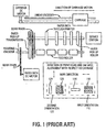
- FIG. 1 illustrates a first type of prior art multi-pass TIJ printer where the service station is stationary, and the carriage moves with respect to the stationary service station.
- the multi-pass printer has nozzles that are positioned in a first orientation 110.
- the first orientation 110 is generally parallel to the direction of carriage motion.
- the black ink firing nozzles 114 are arranged generally in a single horizontal band.
- the color ink firing nozzles 118 are arranged generally in horizontal bands stack upon each other with each band having nozzles for a particular color (e.g., cyan, magenta and yellow).
- This type of printer requires multiple passes to complete a printing job.
- a piece of paper is fed through a paper path in the printer.
- a feed roller and other rollers are driven by a plurality of gear trains that are driven by a paper path DC motor.
- a carriage moves generally in the directions shown and is driven by a carriage DC motor.
- a linear encoder is also provided for controlling the movement of the carriage.
- the carriage includes a plurality of pens that deposit ink onto the paper.
- a stationary service station is provided for maintaining the pens. Maintenance of the pens involves periodically wiping the pens and capping the pens when the pens are not in use.
- TIJ printers e.g., Lexmark brand TIJ printers
- the pens move to the far rightside of the printer, where the pens hit a lever that moves the caps into place.
- the pens are moved to the extreme left of the printer. The start of this movement releases the capping switch and lowers the caps halfway, thereby bringing the wipers into position.
- the orifices are wiped.
- the pen motion pulls the wipers into a "rest" position that does not interfere with the normal operation of the carriage.
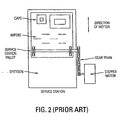
- FIG. 2 illustrates a second type of prior art single-pass TIJ printer where a dedicated motor controls the movement of the service station.
- the single-pass printer (also referred to as a complete swath printer) has nozzles that are positioned in an second orientation 120 that is generally perpendicular to the direction of carriage motion, thereby enabling all the different color nozzles to fire simultaneously.
- the black ink firing nozzles 124 are arranged generally in a single vertical band.
- the color ink firing nozzles 128 are arranged generally in vertical bands that are arranged adjacent to with each other with each vertical band having nozzles for a particular color (e.g., cyan, magenta and yellow). Examples of this type of TIJ printer include the Hewlett-Packard 800 and 900 series.
- motion of a service station (e.g., the service station pallet) is required to perform the pen-servicing operations.
- This motion is achieved by using a stepper motor to maneuver the entire service station assembly.
- the wiping function performed by the service station has an additional complication.
- This complication is that the service station needs to be moved in a particular manner with respect to the firing nozzles in order to prevent cross-contamination of the ink.
- perpendicular TIJ printers provide an isolated space for the spittoon and move that spittoon into position. The isolation keeps the excess ink away from the other contents of the printer.
- the Hewlett-Packard type of single-pass printers utilize a platform, a separate dedicated motor to drive the platform, and one or more gear trains for transferring the motion of the motor to the platform. These components are needed to cause the wiper blades that are mounted on the platform to perform the maintenance functions of the service station. As can be appreciated, these components increase the weight, cost, and complexity of the printer.
- US 4,935,753 shows an apparatus for sealing and cleaning the nozzle surface of an ink head.
- the sealing and cleaning apparatus for an ink head consists of an electromotively driven endless band, on which two wedge-shaped wiping lips are arranged.
- the nozzle head is brought in a close distance in front of the endless band.
- a surface of the endless band not provided with wiping lips serves as a spraying surface for the squirting-out of the ink head.
- a cleaning device of wiping edge or cleaning roller removes the ink on the endless band.
- the endless band has a depression formed by bulges, which is brought into contact in front of the nozzle plate or covering.
- a convexly formed flexible pad which is arranged between the endless belt, is pressed by means of a pressure-applying device against the endless band and consequently against the nozzle plate. Due to the convex form, no air entrapment can occur in the region of the nozzle plate.
- US 5,774,139 shows a vertical axis service station adjustment device and method.
- the adjustment device includes a base, a pair of ramps, and an adjustment mechanism.
- the base is slideably mounted on the chassis so as to be capable of translation along the plane defined by the chassis.
- the ramps are coupled to the base and each define an angled track that supports the service station and with respect to which a member of the service station rides during translation of the base.
- the adjustment mechanism is coupled to the base and is actuable to translate the base along the plane, thereby moving the angled track of each ramp with respect to the member of the service station on that track, which results in movement of the service station in a direction that is at an angle to the plane defined by the chassis.
- a conventional service station drive motor such as a stepper motor, may be used in the service station.
- the motor has upper and lower mounting points, with the upper mount being secured to the frame base using a clip member that extends outwardly from the outboard of the base.
- a main feature of the reversed shaft mechanism is a continuous rotator motion of a main shaft in only one direction, eliminating the need for a reversible stepping motor.
- the reverse and forward motion is provided by two segment gears to respective forward and reverse shafts. It uses the motion of a stepper motor to drive a wiper or a capping mechanism by way of a gear affixed to the main shaft.
- Non pre-published EP 1 208 993 A1 shows a service station for printers having nozzles perpendicular to a direction of carriage motion.
- An inkjet printer having nozzles perpendicular to the carriage motion has two motors: paper and carriage. These motors, alone or in concert, provide the power to the service station.
- the service station has separate wiping and pen cleaning functions.
- the wipers need to move across the pens in a direction that is perpendicular to the carriage motion. Through the use of gears, the wipers can be made to clean the pens at the same time that the paper is being advanced and using the same motor source. For capping, the caps are moved into place as the pens come to rest. The motion of the pens can push a lever that pulls the cap into place.
- One method for providing a "wipe” function is to mold a reinforced ethylene, propylene, diene modified co-polymer (EPDM) continuous belt, similar to a conveyor belt. Squeegee elements would be moulded onto the outer surface of the belt. This "squeegee belt” is mounted on two rollers that contact the surface of the belt.
- EPDM diene modified co-polymer
- a service station for maintaining or servicing pens.
- the service station includes a treadmill belt that has an outer surface and an inner surface. At least one wiper is positioned on the outer surface of the treadmill belt.
- the treadmill belt is mounted on a first roller and a second roller. The first roller and the second roller contact the inner surface of the treadmill belt for driving the treadmill belt.
- Either the first roller or the second roller can be coupled to a drive axle.
- the drive axle is coupled to a paper motor via a paper drive shaft.
- the wiper can be, for example, a flicker squeegee or a wicking squeegee.
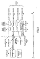
- FIG. 3 illustrates a top view of a service station 20 in accordance with one embodiment of the present invention.
- One primary function of the service station 20 is to move wipers with respect to the print head in order to maintain and clean the print head.
- the wipers move across the pens in a direction that is parallel to the direction that the paper moves in order to preserve the ink supply.
- the wipers can be made to clean the pens at the same time that the paper is being advanced, using the same motor source.
- the service station of the present invention also performs a capping function. This function requires moving the caps into place as the pens come to rest. The motion of the pens themselves could easily push a lever that pushes the caps into place. A spittoon collects the residual ink.
- the service station 20 includes a conveyor belt 24 (also referred to herein as a treadmill belt) that has an outer surface 26 and an inner surface 28. At least one wiper 32 is positioned on the outer surface 26 of the conveyor belt 24. The function and operation of the different types of wipers 32 are described in greater detail hereinafter.
- the service station 20 also includes a first roller 34, which can be a treadmill drive roller, and a second roller 38, which can be a treadmill response roller.
- the conveyor belt 24 is mounted on the first roller 34 and the second roller 38 in such a manner that the first roller 34 and the second roller 38 contact the inner surface 28 of the conveyor belt 24 for driving the belt 24.
- the conveyor belt 24 can also include one or more pen caps, such as a first pen cap 44 for the black ink pen 64 (e.g., a black pen cap) and a second pen cap 45 for the color ink pen 65 (e.g., a color pen cap).
- a first pen cap 44 for the black ink pen 64 e.g., a black pen cap
- a second pen cap 45 for the color ink pen 65 e.g., a color pen cap
- the service station 20 includes a set of caps with one cap for each pen head.
- the pens are positioned over the service station 20, and the caps are moved by the service station 20 to cover the firing heads.
- the caps e.g., caps 44 and 45
- the treadmill belt 24 of the present invention provides the motion of the service station 20 with respect to the pens 64, 65 to enable the capping and wiping functions.
- a drive axle 46 is coupled to either the first roller 34 or the second roller 38.
- the drive axle 46 is preferably a paper roller that extends from a paper motor 48.
- the wipers 32 can include, for example, a black flicker squeegee 52, a color flicker squeegee 54, a black wicking squeegee 56, and a color wicking squeegee 58.
- the wipers 32 can include short and stiff wipers.
- the wipers 32 can include long and flexible wipers.
- the wipers 32 are rubber squeegees that are manufactured from an ethylene, propylene diene modified co-polymer material.
- the service station 20 of the present invention provides two pen wipe motions: 1) a wicking motion and 2) a flicker motion.
- the wiper blade 32 may have any topology ranging from short and stiff to long and flexible.
- the wicking squeegee blade is slowly dragged across the pen head in order to pull some wet ink from each nozzle, thereby dissolving dried ink.
- the flicker squeegee blade is rapidly drawn across the orifices to wipe excess ink from the pen. Because of these different types of motion, the service station 20 of the present invention preferably provides different speed controls for the treadmill belt 24.
- the service station 20 includes flicker cleaners (e.g., a black flicker cleaner 60 and a color flicker cleaner 62) that are disposed on one wall of the station 20 for removing excess ink from the wipers 32 when the wipers 32 contact the cleaners 60,62.
- flicker cleaners e.g., a black flicker cleaner 60 and a color flicker cleaner 62
- the service station 20 of the present invention perform the ink removal by wiping the squeegees 32 across cleaners 60, 62, which may be a fixed plastic section extending from a wall of the service station sub-assembly 20.
- the treadmill belt 24 is moved by rotating the rollers 34, 38, so that the squeegees 32 come into contact with the flicker cleaners 60, 62.
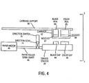
- FIG. 4 illustrates a front view of the service station 20 of FIG. 3.
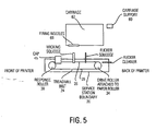
- FIG. 5 illustrates a side view of a service station 20 of FIG. 3.
- a carriage support 60 for supporting a carriage 62 can be seen.
- the carriage 62 is slidably mounted on the carriage support 60 for motion along a first direction 63 and can include a black pen 62 and a color pen 64.
- the black pen 62 has a plurality of firing nozzles 67 for depositing black ink.
- the color pen 64 has a plurality of firing nozzles 68 for depositing different color inks (e.g., cyan color ink, magenta color ink, and yellow color ink).
- the firing nozzles are configured in the second orientation 120 as shown in FIG. 1.
- these pens 64, 65 may be capped with caps 44, 45, respectively when the carriage 62 is positioned in proximity to the caps 44, 45 of the service station 20.
- a direction switch 70 and a direction gear 74 are provided to switch the direction of travel of the treadmill belt 24.
- the direction gear 74 translates the motion of the paper roller 46 into either a first direction or a second direction as set by the direction switch 70.
- the direction switch 70 has first position and a second position. When the direction switch 70 is in the first position, the direction gear 74 translates the motion of the paper roller 46 into the first direction. When the direction switch 70 is in the second position, the direction gear 74 translates the motion of the paper roller 46 into the second direction. In this manner, the direction of travel (e.g., forward or backward) of the treadmill belt 24 can be controlled.
- the service station 20 of the present invention maintains the pens (e.g., pens 64 and 65) by performing the following steps. First, a rubber blade that is passed over the firing orifices, thereby cleaning them of excess ink. For example, the rubber blade (e.g., the flicker squeegees 52, 54 and wicking squeegees 56, 58) can periodically wipe the pens 64 and 65. When the pens are not being maintained, the service station sub-assembly 20 is placed on one side of the paper path.
- a rubber blade e.g., the flicker squeegees 52, 54 and wicking squeegees 56, 58
- the pen carriage 62 moves the pens 64, 65 over the treadmill belt 24; the paper roller 46 turns, and the squeegees 32 are moved across the orifice plate. Mounting the treadmill belt 24 in this orientation provides the correct squeegee motion for pens that move perpendicular to the carriage axis.
- all the pens are periodically fired into a spittoon (not shown). For example, this step can occur at intervals when the dot-count reaches a certain value. This dot-count indicates that a set of the orifices within a pen have been fired a certain number of times, while other orifices within the same pen have not.
- the carriage is positioned over the spittoon, and all the orifices are fired. This step has the effect of ensuring the reservoirs maintain the appropriate level of pressure and fluidity, and ensuring that all the orifices do not clog or weep.
- the treadmill belt 24 is made from a reinforced, ethylene, propylene diene modified (EPDM) co-polymer material
- EPDM reinforced, ethylene, propylene diene modified
- the squeegee elements are preferably molded on the outer surface of the belt.
- This treadmill belt is mounted on two rollers that contact the surface of the belt. One roller is an idler, and the other roller is affixed to the drive roller.
- a transmission may be provided to engage the treadmill belt upon demand.
- the pen carriage can trip the transmission when it is in position for a wipe.
- the wipe cannot be performed while paper is loaded in the drive roller.
- the pen wipe can be performed during the pen-cap and pen-uncap steps.
- the axial motion of the carriage can be transformed into perpendicular-to-axial motion for the wipers through a number of mechanical means (e.g. levers, gears, springs, or a combination thereof).
- the carriage motion may be used to raise and lower the pen caps also through a series of levers, gears, springs, or a combination thereof.
- the treadmill belt 24 can be widened to accommodate the different wiping elements.
- the different wiping elements can be arranged in a side-by-side manner as shown in FIG. 3.
- the different wiping elements can be arranged in a column configuration, but offset from each other, at different locations along the length of the belt as shown in FIG. 8.
- the belt is wider, and the print heads on the carriage are placed over a different position on the belt. The wiping action is the same as described previously.
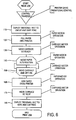
- FIG. 6 is a flowchart that describes the general steps performed by the service station of the present invention in accordance with one embodiment of the present invention.
- the printer gains operational control of the job.
- the pens are uncapped and wiped.
- paper is pulled into the printer.
- the carriage is initialized.
- the paper is advanced.
- the carriage is moved and ink is spit onto the paper. Steps 140 and 150 are repeated until the print job is complete. A new piece of paper is loaded without servicing the pens.
- the rest of the flow chart corresponds to when the last page is printed.
- the paper is "kicked" from the printer, coming to rest in the out tray.
- step 170 the carriage is moved to the "rest" position.
- step 180 pens are wiped and capped. It is noted that the pen servicing can also occur periodically during a print job (e.g., when a predetermined number of drops of ink have been fired) without regard to state of paper load or the length of the job.
- FIG. 7 illustrates a process flowchart corresponding to a thermal inkjet printer having a paper motor coupled to the service station.
- the printer gains operational control of the job.
- the pens are uncapped and wiped.
- paper is pulled into the printer. Steps 310 and 320 may occur simultaneously.
- the carriage is initialized.
- the paper is -advance.
- the carriage is moved and ink is spit onto he paper. Steps 340 and 350 are repeated until the job is printed.
- step 360 the carriage is moved into the "rest" position.
- the pens are wiped and capped.
- the paper is "kicked" from the printer. Steps 370 and 380 may occur simultaneously.
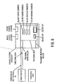
- FIG. 8 illustrates a side view of a service station configured in accordance with another embodiment of the present invention, where the wiping elements are placed in a line.
- the wiping elements e.g., the black flicker squeegee, the color flicker squeegee, the black wicking squeegee, and the color wicking squeegee
- the wiping elements are positioned in a line format.
- the service station assembly may be made smaller in size.
- the paper motor transfers power to the service station
- other motors e.g., the carriage motor or a separate dedicated motor
- the carriage motor or a separate dedicated motor may be used individually or in concert to transfer power to the service station.
- the service station of the present invention for a single-pass TIJ printer has a simplified and more compact design than prior art solutions previously described.
- the service station of the present invention has a simplified drive train that has fewer parts (e.g., gears), is lighter, and is easier to assemble than the service stations in prior art single pass TIJ printers.
- the service station of the present invention reduces manufacturing costs and complexity.
Description
- The present invention relates generally to thermal inkjet (TIJ) printers, and more particularly, to a method and system for maintaining pens in thermal inkjet printers that employs a treadmill belt.
- Thermal inkjet (TIJ) printers are now commonly found in homes and offices. TIJ printers offer good print quality at a very affordable price. TIJ printers employ pens to apply ink to paper or other printing medium. For example, a black pen is provided for printing black ink. Similarly, a multi-color pen is utilized to apply color inks to a paper. Each pen typically includes a cavity for holding the ink and a nib for delivering the ink. The nib holds a print head, which is typically made of a silicon material that controls the delivery of the ink. The print head includes hundreds of orifices through which ink is delivered.
- Some orifices are fired very frequently. Other orifices are fired very infrequently. In any case, inkjet pens require frequent wiping to remove excess ink from the orifices and to prevent ink depositions from hardening in or around the orifices. As can be appreciated, hardened ink deposits can cause the orifices to clog or jam, thereby adversely affecting print quality.
- Currently, some thermal inkjet (TIJ) printers include a sub-assembly that is often referred to as a "service station" for maintaining the TIJ pens. The service station maintains the pens by wiping excess ink from the orifice, thereby increasing the life of the pens and enhancing the performance of the pens.
- FIG. 1 illustrates a first type of prior art multi-pass TIJ printer where the service station is stationary, and the carriage moves with respect to the stationary service station. The multi-pass printer has nozzles that are positioned in a
first orientation 110. Thefirst orientation 110 is generally parallel to the direction of carriage motion. The blackink firing nozzles 114 are arranged generally in a single horizontal band. Similarly, the colorink firing nozzles 118 are arranged generally in horizontal bands stack upon each other with each band having nozzles for a particular color (e.g., cyan, magenta and yellow). This type of printer requires multiple passes to complete a printing job. - A piece of paper is fed through a paper path in the printer. A feed roller and other rollers are driven by a plurality of gear trains that are driven by a paper path DC motor. A carriage moves generally in the directions shown and is driven by a carriage DC motor. A linear encoder is also provided for controlling the movement of the carriage. The carriage includes a plurality of pens that deposit ink onto the paper. A stationary service station is provided for maintaining the pens. Maintenance of the pens involves periodically wiping the pens and capping the pens when the pens are not in use.
- For these printers, the motion required for wiping and capping the pens is parallel to the direction of the pen movement on the carriage. These TIJ printers (e.g., Lexmark brand TIJ printers) use the motion of the pens across the paper, which is driven by the carriage DC motor, and a stationary service station to service the pens.
- At the end of a print job, the pens move to the far rightside of the printer, where the pens hit a lever that moves the caps into place. When a new print job starts, the pens are moved to the extreme left of the printer. The start of this movement releases the capping switch and lowers the caps halfway, thereby bringing the wipers into position. As the pens continue their motion, the orifices are wiped. After the final wiping motion is completed, the pen motion pulls the wipers into a "rest" position that does not interfere with the normal operation of the carriage.
- One disadvantage of these types of printers is the speed at which pages are printed, which is typically measured by the number of pages per minute. As can be appreciated, multi-pass type printers typically take a longer time to print pages than a single-pass printer that is described in greater detail hereinafter. Consequently, as the demand for printers that have faster printing speeds increases, the demand for single-pass printers increases proportionately.
- One benefit of a stationary service station is that the arrangement is relatively cost-effective. Unfortunately, this type of arrangement for pen servicing and maintenance is not suitable for single-pass printers for the reasons set forth hereinafter.
- FIG. 2 illustrates a second type of prior art single-pass TIJ printer where a dedicated motor controls the movement of the service station. The single-pass printer (also referred to as a complete swath printer) has nozzles that are positioned in an
second orientation 120 that is generally perpendicular to the direction of carriage motion, thereby enabling all the different color nozzles to fire simultaneously. The blackink firing nozzles 124 are arranged generally in a single vertical band. Similarly, the colorink firing nozzles 128 are arranged generally in vertical bands that are arranged adjacent to with each other with each vertical band having nozzles for a particular color (e.g., cyan, magenta and yellow). Examples of this type of TIJ printer include the Hewlett-Packard 800 and 900 series. - For these printers, motion of a service station (e.g., the service station pallet) is required to perform the pen-servicing operations. This motion is achieved by using a stepper motor to maneuver the entire service station assembly.
- For multiple colors, the wiping function performed by the service station has an additional complication. This complication is that the service station needs to be moved in a particular manner with respect to the firing nozzles in order to prevent cross-contamination of the ink.
- In color printers, if the wiper crosses from cyan to magenta to yellow, the color inks contaminate each other. In other words, when one wiper blade services multiple colors, and a particular portion of the wiper (e.g., a particular wiper surface) is passed over firing nozzles of different colors, the ink supplies are contaminated.
- When the wiping motion runs along a single color without crossing different color boundaries (i.e., a particular portion of the wiper passes over firing nozzles of a single color), then the inks do not contaminate each other. Consequently, it is important in the design of the service station that the direction of the wipe is ensured to be along the same direction as the placement of the firing nozzles of the print head.
- Additionally, perpendicular TIJ printers provide an isolated space for the spittoon and move that spittoon into position. The isolation keeps the excess ink away from the other contents of the printer.
- It is noted that the Hewlett-Packard type of single-pass printers utilize a platform, a separate dedicated motor to drive the platform, and one or more gear trains for transferring the motion of the motor to the platform. These components are needed to cause the wiper blades that are mounted on the platform to perform the maintenance functions of the service station. As can be appreciated, these components increase the weight, cost, and complexity of the printer.
-
US 4,935,753 shows an apparatus for sealing and cleaning the nozzle surface of an ink head. The sealing and cleaning apparatus for an ink head consists of an electromotively driven endless band, on which two wedge-shaped wiping lips are arranged. For cleaning and sealing, the nozzle head is brought in a close distance in front of the endless band. A surface of the endless band not provided with wiping lips serves as a spraying surface for the squirting-out of the ink head. A cleaning device of wiping edge or cleaning roller removes the ink on the endless band. For covering in breaks of recording, the endless band has a depression formed by bulges, which is brought into contact in front of the nozzle plate or covering. For sealing, a convexly formed flexible pad, which is arranged between the endless belt, is pressed by means of a pressure-applying device against the endless band and consequently against the nozzle plate. Due to the convex form, no air entrapment can occur in the region of the nozzle plate. -
US 5,774,139 shows a vertical axis service station adjustment device and method. The adjustment device includes a base, a pair of ramps, and an adjustment mechanism. The base is slideably mounted on the chassis so as to be capable of translation along the plane defined by the chassis. The ramps are coupled to the base and each define an angled track that supports the service station and with respect to which a member of the service station rides during translation of the base. The adjustment mechanism is coupled to the base and is actuable to translate the base along the plane, thereby moving the angled track of each ramp with respect to the member of the service station on that track, which results in movement of the service station in a direction that is at an angle to the plane defined by the chassis. A conventional service station drive motor, such as a stepper motor, may be used in the service station. Preferably, the motor has upper and lower mounting points, with the upper mount being secured to the frame base using a clip member that extends outwardly from the outboard of the base. - The article "Reversed Shaft Mechanism" of R.H. Berg, published in the Xerox Disclosure Journal, Vol. 21, No. 2, March - April 2001, describes a maintenance station designed for wiping or capping an inkjet print head. A main feature of the reversed shaft mechanism is a continuous rotator motion of a main shaft in only one direction, eliminating the need for a reversible stepping motor. The reverse and forward motion is provided by two segment gears to respective forward and reverse shafts. It uses the motion of a stepper motor to drive a wiper or a capping mechanism by way of a gear affixed to the main shaft.
- Non pre-published
EP 1 208 993 A1 shows a service station for printers having nozzles perpendicular to a direction of carriage motion. An inkjet printer having nozzles perpendicular to the carriage motion has two motors: paper and carriage. These motors, alone or in concert, provide the power to the service station. The service station has separate wiping and pen cleaning functions. The wipers need to move across the pens in a direction that is perpendicular to the carriage motion. Through the use of gears, the wipers can be made to clean the pens at the same time that the paper is being advanced and using the same motor source. For capping, the caps are moved into place as the pens come to rest. The motion of the pens can push a lever that pulls the cap into place. - One method for providing a "wipe" function is to mold a reinforced ethylene, propylene, diene modified co-polymer (EPDM) continuous belt, similar to a conveyor belt. Squeegee elements would be moulded onto the outer surface of the belt. This "squeegee belt" is mounted on two rollers that contact the surface of the belt.
- As the costs of printers decreases and the competition in the thermal inkjet printer market increases, there is a constant demand for designs for the various sub-assemblies that can reduce the number of parts needed for a particular sub-assembly and hence reduce the costs associated with manufacturing the printer.
- Consequently, it is desirable for there to be a service station that performs the wiping and cleaning functions of prior art service station while at the same time reducing the part count and costs associated with the manufacture of the service station.
- Based on the foregoing, there remains a need for pen maintenance method and system for thermal inkjet printers that overcomes the disadvantages set forth previously.
- According to one embodiment of the present invention, a service station for maintaining or servicing pens is provided. The service station includes a treadmill belt that has an outer surface and an inner surface. At least one wiper is positioned on the outer surface of the treadmill belt. The treadmill belt is mounted on a first roller and a second roller. The first roller and the second roller contact the inner surface of the treadmill belt for driving the treadmill belt. Either the first roller or the second roller can be coupled to a drive axle. Preferably, the drive axle is coupled to a paper motor via a paper drive shaft. The wiper can be, for example, a flicker squeegee or a wicking squeegee.
- The present invention is illustrated by way of example, and not by way of limitation, in the figures of the accompanying drawings and in which like reference numerals refer to similar elements.
- FIG. 1 illustrates a first type of prior art multi-pass TIJ printer where the service station is stationary, and the carriage moves with respect to the stationary service station.
- FIG. 2 illustrates a second type of prior art single-pass TIJ printer where a dedicated motor controls the movement of the service station.
- FIG. 3 illustrates a top view of a service station in accordance with one embodiment of the present invention.
- FIG. 4 illustrates a front view of the service station of FIG. 3.
- FIG. 5 illustrates a side view of a service station of FIG. 3, where the wiping elements are placed in a side-by-side configuration.
- FIG. 6 is a flowchart illustrating the processing steps performed by a thermal inkjet printer having a service station that uses a treadmill belt.
- FIG. 7 is a flowchart illustrating the processing steps performed by a thermal inkjet printer having a service station with a service station that is powered by the paper motor.
- FIG. 8 illustrates a side view of a service station configured in accordance with another embodiment of the present invention, where the wiping elements are placed in a column configuration.
- A pen wiping method and system for inkjet printers are described. In the following description, for the purposes of explanation, numerous specific details are set forth in order to provide a thorough understanding of the present invention. It will be apparent, however, to one skilled in the art that the present invention may be practiced without these specific details. In other instances, well-known structures and devices are shown in block diagram form in order to avoid unnecessarily obscuring the present invention.
- FIG. 3 illustrates a top view of a
service station 20 in accordance with one embodiment of the present invention. One primary function of theservice station 20 is to move wipers with respect to the print head in order to maintain and clean the print head. In one embodiment, the wipers move across the pens in a direction that is parallel to the direction that the paper moves in order to preserve the ink supply. - Through the use of gears connected to the paperrollers, the wipers can be made to clean the pens at the same time that the paper is being advanced, using the same motor source.
- The service station of the present invention also performs a capping function. This function requires moving the caps into place as the pens come to rest. The motion of the pens themselves could easily push a lever that pushes the caps into place. A spittoon collects the residual ink.
- The
service station 20 includes a conveyor belt 24 (also referred to herein as a treadmill belt) that has anouter surface 26 and aninner surface 28. At least onewiper 32 is positioned on theouter surface 26 of theconveyor belt 24. The function and operation of the different types ofwipers 32 are described in greater detail hereinafter. - The
service station 20 also includes afirst roller 34, which can be a treadmill drive roller, and asecond roller 38, which can be a treadmill response roller. Theconveyor belt 24 is mounted on thefirst roller 34 and thesecond roller 38 in such a manner that thefirst roller 34 and thesecond roller 38 contact theinner surface 28 of theconveyor belt 24 for driving thebelt 24. - The
conveyor belt 24 can also include one or more pen caps, such as afirst pen cap 44 for the black ink pen 64 (e.g., a black pen cap) and asecond pen cap 45 for the color ink pen 65 (e.g., a color pen cap). - Preferably, the
service station 20 includes a set of caps with one cap for each pen head. During the times when the printer is not in use, the pens are positioned over theservice station 20, and the caps are moved by theservice station 20 to cover the firing heads. The caps (e.g., caps 44 and 45) protect the ink in the orifices from drying out during periods of non-use. Thetreadmill belt 24 of the present invention provides the motion of theservice station 20 with respect to thepens - A
drive axle 46 is coupled to either thefirst roller 34 or thesecond roller 38. Preferably, thedrive axle 46 is preferably a paper roller that extends from apaper motor 48. - The
wipers 32 can include, for example, ablack flicker squeegee 52, acolor flicker squeegee 54, ablack wicking squeegee 56, and acolor wicking squeegee 58. In one embodiment, thewipers 32 can include short and stiff wipers. In another embodiment, thewipers 32 can include long and flexible wipers. Preferably, thewipers 32 are rubber squeegees that are manufactured from an ethylene, propylene diene modified co-polymer material. - The
service station 20 of the present invention provides two pen wipe motions: 1) a wicking motion and 2) a flicker motion. Thewiper blade 32 may have any topology ranging from short and stiff to long and flexible. To achieve a wicking motion, the wicking squeegee blade is slowly dragged across the pen head in order to pull some wet ink from each nozzle, thereby dissolving dried ink. To achieve a flicker motion, the flicker squeegee blade is rapidly drawn across the orifices to wipe excess ink from the pen. Because of these different types of motion, theservice station 20 of the present invention preferably provides different speed controls for thetreadmill belt 24. - The
service station 20 includes flicker cleaners (e.g., ablack flicker cleaner 60 and a color flicker cleaner 62) that are disposed on one wall of thestation 20 for removing excess ink from thewipers 32 when thewipers 32 contact thecleaners squeegees 32. Theservice station 20 of the present invention perform the ink removal by wiping thesqueegees 32 acrosscleaners service station sub-assembly 20. In one embodiment, after a pen wipe, thetreadmill belt 24 is moved by rotating therollers squeegees 32 come into contact with theflicker cleaners - FIG. 4 illustrates a front view of the
service station 20 of FIG. 3. FIG. 5 illustrates a side view of aservice station 20 of FIG. 3. In FIGS. 4 and 5, acarriage support 60 for supporting acarriage 62 can be seen. Thecarriage 62 is slidably mounted on thecarriage support 60 for motion along a first direction 63 and can include ablack pen 62 and acolor pen 64. Theblack pen 62 has a plurality of firingnozzles 67 for depositing black ink. Similarly, thecolor pen 64 has a plurality of firingnozzles 68 for depositing different color inks (e.g., cyan color ink, magenta color ink, and yellow color ink). The firing nozzles are configured in thesecond orientation 120 as shown in FIG. 1. - As described previously, these
pens caps carriage 62 is positioned in proximity to thecaps service station 20. - A
direction switch 70 and adirection gear 74 are provided to switch the direction of travel of thetreadmill belt 24. Thedirection gear 74 translates the motion of thepaper roller 46 into either a first direction or a second direction as set by thedirection switch 70. The direction switch 70 has first position and a second position. When thedirection switch 70 is in the first position, thedirection gear 74 translates the motion of thepaper roller 46 into the first direction. When thedirection switch 70 is in the second position, thedirection gear 74 translates the motion of thepaper roller 46 into the second direction. In this manner, the direction of travel (e.g., forward or backward) of thetreadmill belt 24 can be controlled. - The
service station 20 of the present invention maintains the pens (e.g., pens 64 and 65) by performing the following steps. First, a rubber blade that is passed over the firing orifices, thereby cleaning them of excess ink. For example, the rubber blade (e.g., the flicker squeegees 52, 54 and wickingsqueegees 56, 58) can periodically wipe thepens service station sub-assembly 20 is placed on one side of the paper path. When the pens require maintenance (i.e., a wipe is needed), thepen carriage 62 moves thepens treadmill belt 24; thepaper roller 46 turns, and thesqueegees 32 are moved across the orifice plate. Mounting thetreadmill belt 24 in this orientation provides the correct squeegee motion for pens that move perpendicular to the carriage axis. - Second, all the pens are periodically fired into a spittoon (not shown). For example, this step can occur at intervals when the dot-count reaches a certain value. This dot-count indicates that a set of the orifices within a pen have been fired a certain number of times, while other orifices within the same pen have not. During this servicing step, the carriage is positioned over the spittoon, and all the orifices are fired. This step has the effect of ensuring the reservoirs maintain the appropriate level of pressure and fluidity, and ensuring that all the orifices do not clog or weep.
- According to one embodiment, the
treadmill belt 24 is made from a reinforced, ethylene, propylene diene modified (EPDM) co-polymer material The EPDM material can be molded into continuous belt for providing the wipe function. The squeegee elements are preferably molded on the outer surface of the belt. This treadmill belt is mounted on two rollers that contact the surface of the belt. One roller is an idler, and the other roller is affixed to the drive roller. - In one embodiment, a transmission may be provided to engage the treadmill belt upon demand. For example, the pen carriage can trip the transmission when it is in position for a wipe. In this embodiment, the wipe cannot be performed while paper is loaded in the drive roller. For example, the pen wipe can be performed during the pen-cap and pen-uncap steps.
- The axial motion of the carriage can be transformed into perpendicular-to-axial motion for the wipers through a number of mechanical means (e.g. levers, gears, springs, or a combination thereof). The carriage motion may be used to raise and lower the pen caps also through a series of levers, gears, springs, or a combination thereof.
- It is noted that when more than one style of wiping element is needed for a certain application, the
treadmill belt 24 can be widened to accommodate the different wiping elements. For example, the different wiping elements can be arranged in a side-by-side manner as shown in FIG. 3. - Alternatively, the different wiping elements can be arranged in a column configuration, but offset from each other, at different locations along the length of the belt as shown in FIG. 8. In this embodiment, the belt is wider, and the print heads on the carriage are placed over a different position on the belt. The wiping action is the same as described previously.
- FIG. 6 is a flowchart that describes the general steps performed by the service station of the present invention in accordance with one embodiment of the present invention. In step 100, the printer gains operational control of the job. In
step 110, the pens are uncapped and wiped. Instep 120, paper is pulled into the printer. Instep 130, the carriage is initialized. Instep 140, the paper is advanced. Instep 150, the carriage is moved and ink is spit onto the paper.Steps step 160, the paper is "kicked" from the printer, coming to rest in the out tray. Instep 170, the carriage is moved to the "rest" position. Instep 180, pens are wiped and capped. It is noted that the pen servicing can also occur periodically during a print job (e.g., when a predetermined number of drops of ink have been fired) without regard to state of paper load or the length of the job. - FIG. 7 illustrates a process flowchart corresponding to a thermal inkjet printer having a paper motor coupled to the service station. In
step 300, the printer gains operational control of the job. Instep 310, the pens are uncapped and wiped. Instep 320, paper is pulled into the printer.Steps step 330, the carriage is initialized. Instep 340, the paper is -advance. Instep 350, the carriage is moved and ink is spit onto he paper.Steps step 360, the carriage is moved into the "rest" position. Instep 370, the pens are wiped and capped. Instep 380, the paper is "kicked" from the printer.Steps - FIG. 8 illustrates a side view of a service station configured in accordance with another embodiment of the present invention, where the wiping elements are placed in a line. In this embodiment, the wiping elements (e.g., the black flicker squeegee, the color flicker squeegee, the black wicking squeegee, and the color wicking squeegee) are positioned in a line format.
- One benefit to placing the wipers along the length of the belt rather than across the width is that there is more available space on the length. For example, with four types of wipers required (i.e., two wipers per color), when the wipers are disposed or placed at different points along the length rather than at the same point in length but across the width, the service station assembly may be made smaller in size.
- While in the preferred embodiment, the paper motor transfers power to the service station, it will be apparent to those with skill in the art that other motors (e.g., the carriage motor or a separate dedicated motor) may be used individually or in concert to transfer power to the service station.
- As can be appreciated, the service station of the present invention for a single-pass TIJ printer has a simplified and more compact design than prior art solutions previously described. Moreover, the service station of the present invention has a simplified drive train that has fewer parts (e.g., gears), is lighter, and is easier to assemble than the service stations in prior art single pass TIJ printers. By employing a treadmill belt for performing the pen servicing functions, the service station of the present invention reduces manufacturing costs and complexity.
Claims (13)
- A service station (20) for pens, for use in a printer, comprising:a) a treadmill belt (24) that has an outer surface (26) and an inner surface (28), wherein the treadmill belt comprises at least one pen cap (44, 45);b) at least one wiper (32) positioned on the outer surface of the treadmill belt;c) a first roller (34);d) a second roller (38);
wherein the treadmill belt is mounted on the first roller and the second roller; and
wherein the first roller and the second roller contact the inner surface of the treadmill belt for driving the treadmill belt;e) a drive axle (46) coupled to one of the first roller or the second roller; and characterised by further comprising
means for coupling the drive axle with a paper motor of the printer. - The service station of claim 1, (32), wherein the wipers can be one of a wicking squeegee (56, 58) or a flicking squeegee (52,54).
- The service station of claim 1, wherein the treadmill belt (24) includes a first pen cap (44) for the black ink pen and a second pen cap (45) for the color ink pen.
- The service station of claim 1, wherein the wiper includes a short and stiff wiper.
- The service station of claim 1, wherein the wiper includes a long and flexible wiper.
- The service station of claim 1, further comprising:a flicker cleaner for use by the wiper to remove excess ink therefrom.
- The service station of claim 1 wherein the wiper is a rubber squeegee that is manufactured from an ethylene, propylene diene modified co-polymer material.
- The service station of claim 1, further comprising:a mechanism for switching the direction of travel of the treadmill belt.
- The service station of claim 8, wherein the mechanism includes a direction switch (70) for selecting a first direction or a second direction of travel; anda direction gear (74) coupled to the direction switch for switching the direction of travel of the treadmill belt.
- The service station of claim 9, wherein the direction switch includes a first position and a second position; and
wherein the direction gear translates the motion of a paper roller into either a first direction or a second direction;
wherein when the direction switch is in the first position, the direction gear translates the motion of the paper roller into the first direction, and when the direction switch is in the second position, the direction gear translates the motion of the paper roller into the second direction. - The service station of one of claims 1 to 10, wherein a paper motor drives the treadmill belt.
- The service station of one of claims 1 to 11, wherein the drive axle is coupled to the paper motor via a paper drive shaft.
- An inkjet printer, comprising:a service station for pens according to one of claims 1 to 12; anda paper motor for advancing paper;wherein the paper motor is coupled with the service station to drive the treadmill belt.
Priority Applications (2)
| Application Number | Priority Date | Filing Date | Title |
|---|---|---|---|
| EP07013413A EP1834786A1 (en) | 2001-09-05 | 2002-06-04 | Pen wiping method and system that employs a treadmill belt |
| EP07013412A EP1834785A1 (en) | 2001-09-05 | 2002-06-04 | Pen wiping method and system that employs a treadmill belt |
Applications Claiming Priority (2)
| Application Number | Priority Date | Filing Date | Title |
|---|---|---|---|
| US09/948,343 US20040155921A1 (en) | 2001-09-05 | 2001-09-05 | Pen wiping method and system that employs a treadmill belt |
| US948343 | 2001-09-05 |
Related Child Applications (2)
| Application Number | Title | Priority Date | Filing Date |
|---|---|---|---|
| EP07013412A Division EP1834785A1 (en) | 2001-09-05 | 2002-06-04 | Pen wiping method and system that employs a treadmill belt |
| EP07013413A Division EP1834786A1 (en) | 2001-09-05 | 2002-06-04 | Pen wiping method and system that employs a treadmill belt |
Publications (2)
| Publication Number | Publication Date |
|---|---|
| EP1291182A1 EP1291182A1 (en) | 2003-03-12 |
| EP1291182B1 true EP1291182B1 (en) | 2007-08-01 |
Family
ID=25487693
Family Applications (3)
| Application Number | Title | Priority Date | Filing Date |
|---|---|---|---|
| EP07013413A Withdrawn EP1834786A1 (en) | 2001-09-05 | 2002-06-04 | Pen wiping method and system that employs a treadmill belt |
| EP02012510A Expired - Fee Related EP1291182B1 (en) | 2001-09-05 | 2002-06-04 | Pen wiping method and system that employs a treadmill belt |
| EP07013412A Withdrawn EP1834785A1 (en) | 2001-09-05 | 2002-06-04 | Pen wiping method and system that employs a treadmill belt |
Family Applications Before (1)
| Application Number | Title | Priority Date | Filing Date |
|---|---|---|---|
| EP07013413A Withdrawn EP1834786A1 (en) | 2001-09-05 | 2002-06-04 | Pen wiping method and system that employs a treadmill belt |
Family Applications After (1)
| Application Number | Title | Priority Date | Filing Date |
|---|---|---|---|
| EP07013412A Withdrawn EP1834785A1 (en) | 2001-09-05 | 2002-06-04 | Pen wiping method and system that employs a treadmill belt |
Country Status (4)
| Country | Link |
|---|---|
| US (2) | US20040155921A1 (en) |
| EP (3) | EP1834786A1 (en) |
| JP (2) | JP2003103790A (en) |
| DE (1) | DE60221473T2 (en) |
Families Citing this family (27)
| Publication number | Priority date | Publication date | Assignee | Title |
|---|---|---|---|---|
| US20040155921A1 (en) * | 2001-09-05 | 2004-08-12 | Simmons Laura Elisabeth | Pen wiping method and system that employs a treadmill belt |
| WO2008124679A1 (en) * | 2007-04-05 | 2008-10-16 | Marvell International Ltd. | Operating mechanism for an inkjet printer |
| US8313165B2 (en) * | 2008-01-16 | 2012-11-20 | Zamtec Limited | Printhead nozzle face wiper with non-linear contact surface |
| US20090179942A1 (en) * | 2008-01-16 | 2009-07-16 | Silverbrook Research Pty Ltd | Printhead maintenance facility with nozzle wiper movable parallel to media feed direction |
| US20090179948A1 (en) * | 2008-01-16 | 2009-07-16 | Silverbrook Research Pty Ltd | Printhead maintenance facility with nozzle face wiper having a single contact blade |
| US8118422B2 (en) * | 2008-01-16 | 2012-02-21 | Silverbrook Research Pty Ltd | Printer with paper guide on the printhead and pagewidth platen rotated into position |
| US20090179947A1 (en) * | 2008-01-16 | 2009-07-16 | Silverbrook Research Pty Ltd | Printhead maintenance facility with nozzle face wiper having independent contact blades |
| US8277025B2 (en) * | 2008-01-16 | 2012-10-02 | Zamtec Limited | Printhead cartridge with no paper path obstructions |
| US20090179962A1 (en) * | 2008-01-16 | 2009-07-16 | Silverbrook Research Pty Ltd | Printhead wiping protocol for inkjet printer |
| US8277026B2 (en) * | 2008-01-16 | 2012-10-02 | Zamtec Limited | Printhead cartridge insertion protocol |
| US7922279B2 (en) * | 2008-01-16 | 2011-04-12 | Silverbrook Research Pty Ltd | Printhead maintenance facility with ink storage and driven vacuum drainage coupling |
| US20090179957A1 (en) * | 2008-01-16 | 2009-07-16 | Silverbrook Research Pty Ltd | Printhead maintenance facility with pagewidth absorbent element |
| US20090179961A1 (en) * | 2008-01-16 | 2009-07-16 | Silverbrook Research Pty Ltd | Printhead maintenance facility with variable speed wiper element |
| US20090179930A1 (en) * | 2008-01-16 | 2009-07-16 | Silverbrook Research Pty Ltd | Printhead priming protocol |
| US20090179951A1 (en) * | 2008-01-16 | 2009-07-16 | Silverbrook Research Pty Ltd | Printhead nozzle face wiper with multiple overlapping skew blades |
| US8277027B2 (en) | 2008-01-16 | 2012-10-02 | Zamtec Limited | Printer with fluidically coupled printhead cartridge |
| US8596769B2 (en) * | 2008-01-16 | 2013-12-03 | Zamtec Ltd | Inkjet printer with removable cartridge establishing fluidic connections during insertion |
| US8246142B2 (en) * | 2008-01-16 | 2012-08-21 | Zamtec Limited | Rotating printhead maintenance facility with symmetrical chassis |
| US20090179954A1 (en) * | 2008-01-16 | 2009-07-16 | Silverbrook Research Pty Ltd | Printhead nozzle face wiper blade with multiple, inclined contact sections |
| JP5061927B2 (en) * | 2008-01-29 | 2012-10-31 | ブラザー工業株式会社 | Liquid ejection device |
| US8342638B2 (en) * | 2009-11-30 | 2013-01-01 | Hewlett-Packard Development Company, L.P. | Servicing article |
| US8919950B2 (en) * | 2011-02-10 | 2014-12-30 | Hewlett-Packard Industrial Printing Ltd. | Pallet transfer device |
| JP2013166299A (en) * | 2012-02-15 | 2013-08-29 | Seiko Epson Corp | Liquid ejection apparatus |
| JP6094097B2 (en) * | 2012-08-31 | 2017-03-15 | セイコーエプソン株式会社 | Belt cleaning apparatus, medium feeding apparatus, and ink jet recording apparatus |
| JP6881992B2 (en) * | 2017-01-31 | 2021-06-02 | キヤノン株式会社 | Inkjet recording device and its control method |
| US10894414B2 (en) * | 2017-03-22 | 2021-01-19 | Hewlett-Packard Development Company, L.P. | Service stations with removable service modules |
| US10874172B2 (en) | 2018-04-04 | 2020-12-29 | Adidas Ag | Articles of footwear with uppers comprising a wound component and methods of making the same |
Family Cites Families (38)
| Publication number | Priority date | Publication date | Assignee | Title |
|---|---|---|---|---|
| US4872026A (en) * | 1987-03-11 | 1989-10-03 | Hewlett-Packard Company | Ink-jet printer with printhead carriage alignment mechanism |
| GB2203994B (en) * | 1987-03-31 | 1991-12-11 | Canon Kk | Liquid injection recording apparatus and liquid-repellent process method used for the apparatus |
| DE3713794A1 (en) * | 1987-04-24 | 1988-11-10 | Siemens Ag | DEVICE FOR CLEANING AND SEALING THE NOZZLE SURFACE OF AN INK HEAD |
| JPH0347754A (en) * | 1989-04-26 | 1991-02-28 | Canon Inc | Ink jet recorder |
| JPH0326546U (en) * | 1989-07-25 | 1991-03-18 | ||
| JP2702256B2 (en) | 1990-02-13 | 1998-01-21 | キヤノン株式会社 | Ink jet recording device |
| JPH04539U (en) | 1990-04-13 | 1992-01-06 | ||
| JPH04539A (en) * | 1990-04-17 | 1992-01-06 | Fujitsu Ltd | Exclusive control system |
| US5103244A (en) * | 1990-07-05 | 1992-04-07 | Hewlett-Packard Company | Method and apparatus for cleaning ink-jet printheads |
| US5548309A (en) | 1990-08-03 | 1996-08-20 | Canon Kabushiki Kaisha | Apparatus and method for wiping an ink jet recording head with control of relative speed between wiper and head |
| JP2929723B2 (en) | 1991-01-11 | 1999-08-03 | セイコーエプソン株式会社 | Inkjet printer |
| EP0575947B1 (en) * | 1992-06-24 | 1997-12-17 | Matsushita Electric Industrial Co., Ltd. | Color electrophotographic apparatus |
| JPH06344565A (en) | 1993-06-07 | 1994-12-20 | Canon Inc | Ink jet recording apparatus |
| US6137504A (en) * | 1993-05-20 | 2000-10-24 | Canon Kabushiki Kaisha | Wiping and recovery of an ink jet head with inclined discharge port surface |
| JPH0623999A (en) * | 1993-06-16 | 1994-02-01 | Seikosha Co Ltd | Ink jet printer |
| US5500660A (en) * | 1993-06-24 | 1996-03-19 | Hewlett-Packard Company | Wiper for inkjet printhead nozzle member |
| JP3082818B2 (en) | 1993-10-04 | 2000-08-28 | セイコーエプソン株式会社 | Ink jet recording device |
| JPH08169159A (en) | 1994-12-16 | 1996-07-02 | Brother Ind Ltd | Ink-jet type printing recording apparatus |
| US5663751A (en) * | 1994-12-22 | 1997-09-02 | Pitney Bowes Inc. | Automatic service station for the printhead of an inkjet printer and method for cleaning the printhead |
| JP3177126B2 (en) * | 1995-06-16 | 2001-06-18 | アルプス電気株式会社 | Thermal printer |
| JPH0911505A (en) * | 1995-06-27 | 1997-01-14 | Canon Inc | Ink jet recording apparatus and method |
| DE69631741T2 (en) * | 1995-07-31 | 2005-03-17 | Hewlett-Packard Co. (N.D.Ges.D.Staates Delaware), Palo Alto | Repair station with translatory movement for color print heads |
| JPH09123470A (en) * | 1995-08-30 | 1997-05-13 | Mita Ind Co Ltd | Ink jet recorder |
| JP2543863Y2 (en) | 1995-08-31 | 1997-08-13 | セイコープレシジョン株式会社 | Inkjet printer |
| US5786830A (en) * | 1995-10-31 | 1998-07-28 | Hewlett-Packard Company | Adaptive wiping system for inkjet printheads |
| JP3378755B2 (en) | 1997-03-10 | 2003-02-17 | ブラザー工業株式会社 | Recovery device for inkjet printer |
| JP3227363B2 (en) * | 1995-11-20 | 2001-11-12 | ブラザー工業株式会社 | Inkjet printer |
| US5949448A (en) * | 1997-01-31 | 1999-09-07 | Hewlett-Packard Company | Fiber cleaning system for inkjet printhead wipers |
| US5893171A (en) * | 1997-05-30 | 1999-04-13 | Ries; Margaret A. | Nursing cover-up |
| JPH11227179A (en) | 1998-02-16 | 1999-08-24 | Seiko Epson Corp | Ink jet printer |
| JPH11320915A (en) | 1998-05-15 | 1999-11-24 | Canon Inc | Ink-jet recording apparatus |
| US6179419B1 (en) * | 1998-09-29 | 2001-01-30 | Hewlett-Packard | Belt driven media handling system with feedback control for improving media advance accuracy |
| EP1010535B1 (en) | 1998-12-15 | 2008-03-05 | Canon Kabushiki Kaisha | Ink jet printing apparatus |
| JP3453531B2 (en) | 1998-12-15 | 2003-10-06 | キヤノン株式会社 | Ink jet recording device |
| JP2000198210A (en) * | 1999-01-06 | 2000-07-18 | Canon Inc | Ink-jet recording apparatus |
| JP2001138546A (en) | 1999-11-17 | 2001-05-22 | Seiko Epson Corp | Ink jet recorder |
| US6561618B1 (en) * | 2000-11-17 | 2003-05-13 | Agilent Technologies, Inc. | Service station for printers having firing nozzles perpendicular to direction of carriage motion |
| US20040155921A1 (en) | 2001-09-05 | 2004-08-12 | Simmons Laura Elisabeth | Pen wiping method and system that employs a treadmill belt |
-
2001
- 2001-09-05 US US09/948,343 patent/US20040155921A1/en not_active Abandoned
-
2002
- 2002-06-04 EP EP07013413A patent/EP1834786A1/en not_active Withdrawn
- 2002-06-04 EP EP02012510A patent/EP1291182B1/en not_active Expired - Fee Related
- 2002-06-04 EP EP07013412A patent/EP1834785A1/en not_active Withdrawn
- 2002-06-04 DE DE60221473T patent/DE60221473T2/en not_active Expired - Lifetime
- 2002-09-04 JP JP2002259143A patent/JP2003103790A/en active Pending
-
2006
- 2006-03-27 US US11/391,095 patent/US7699432B2/en not_active Expired - Fee Related
-
2010
- 2010-03-10 JP JP2010053204A patent/JP4939620B2/en not_active Expired - Fee Related
Non-Patent Citations (1)
| Title |
|---|
| None * |
Also Published As
| Publication number | Publication date |
|---|---|
| JP4939620B2 (en) | 2012-05-30 |
| EP1291182A1 (en) | 2003-03-12 |
| JP2003103790A (en) | 2003-04-09 |
| EP1834785A1 (en) | 2007-09-19 |
| DE60221473D1 (en) | 2007-09-13 |
| EP1834786A1 (en) | 2007-09-19 |
| US20040155921A1 (en) | 2004-08-12 |
| US7699432B2 (en) | 2010-04-20 |
| US20060170728A1 (en) | 2006-08-03 |
| JP2010125854A (en) | 2010-06-10 |
| DE60221473T2 (en) | 2007-11-29 |
Similar Documents
| Publication | Publication Date | Title |
|---|---|---|
| EP1291182B1 (en) | Pen wiping method and system that employs a treadmill belt | |
| US8029092B2 (en) | Printing apparatus | |
| EP0913263B1 (en) | Hide-away wiper cleaner for inkjet printheads | |
| EP0732211B1 (en) | Independent service stations for multiple printheads in inkjet printers | |
| US5786830A (en) | Adaptive wiping system for inkjet printheads | |
| EP0709203B1 (en) | Multiple wiper servicing system for inkjet printheads | |
| US20010000434A1 (en) | Contoured cross-sectional wiper for cleaning inkjet printheads | |
| EP0730965B1 (en) | Translational wiping technique for an inkjet printhead | |
| EP1208993B1 (en) | A service station for printers having firing nozzles perpendicular to direction of carriage motion | |
| EP0914953B1 (en) | Electrical interconnect cleaning system for inkjet cartridges | |
| JP4363510B2 (en) | Inkjet printing system | |
| US6402291B1 (en) | Composite wiper for inkjet printheads | |
| EP0913262A1 (en) | Narrow and wide wiper blade cleaning system for ink jet printheads | |
| EP2979875B1 (en) | Inkjet image forming apparatus and cleaning method for inkjet image forming apparatus | |
| US7926906B2 (en) | Ink jet printing apparatus and ink absorber recovery method | |
| US20030202035A1 (en) | Independent wiping of printhead | |
| JPH10138521A (en) | Ink jet printer | |
| JPH10138588A (en) | Ink jet printer | |
| US20090073220A1 (en) | Bidirectional printhead maintenance systems, methods and apparatus | |
| JPH10138516A (en) | Ink jet printer |
Legal Events
| Date | Code | Title | Description |
|---|---|---|---|
| PUAI | Public reference made under article 153(3) epc to a published international application that has entered the european phase |
Free format text: ORIGINAL CODE: 0009012 |
|
| AK | Designated contracting states |
Kind code of ref document: A1 Designated state(s): AT BE CH CY DE DK ES FI FR GB GR IE IT LI LU MC NL PT SE TR |
|
| AX | Request for extension of the european patent |
Extension state: AL LT LV MK RO SI |
|
| 17P | Request for examination filed |
Effective date: 20030305 |
|
| AKX | Designation fees paid |
Designated state(s): DE FR GB |
|
| RAP1 | Party data changed (applicant data changed or rights of an application transferred) |
Owner name: AVAGO TECHNOLOGIES IMAGING IP(SINGAPORE) PTE. LTD. |
|
| GRAP | Despatch of communication of intention to grant a patent |
Free format text: ORIGINAL CODE: EPIDOSNIGR1 |
|
| GRAS | Grant fee paid |
Free format text: ORIGINAL CODE: EPIDOSNIGR3 |
|
| GRAA | (expected) grant |
Free format text: ORIGINAL CODE: 0009210 |
|
| AK | Designated contracting states |
Kind code of ref document: B1 Designated state(s): DE FR GB |
|
| REG | Reference to a national code |
Ref country code: GB Ref legal event code: FG4D |
|
| REF | Corresponds to: |
Ref document number: 60221473 Country of ref document: DE Date of ref document: 20070913 Kind code of ref document: P |
|
| ET | Fr: translation filed | ||
| PLBE | No opposition filed within time limit |
Free format text: ORIGINAL CODE: 0009261 |
|
| STAA | Information on the status of an ep patent application or granted ep patent |
Free format text: STATUS: NO OPPOSITION FILED WITHIN TIME LIMIT |
|
| 26N | No opposition filed |
Effective date: 20080506 |
|
| REG | Reference to a national code |
Ref country code: FR Ref legal event code: TP |
|
| REG | Reference to a national code |
Ref country code: FR Ref legal event code: PLFP Year of fee payment: 15 |
|
| PGFP | Annual fee paid to national office [announced via postgrant information from national office to epo] |
Ref country code: GB Payment date: 20160627 Year of fee payment: 15 |
|
| PGFP | Annual fee paid to national office [announced via postgrant information from national office to epo] |
Ref country code: FR Payment date: 20160628 Year of fee payment: 15 |
|
| PGFP | Annual fee paid to national office [announced via postgrant information from national office to epo] |
Ref country code: DE Payment date: 20160628 Year of fee payment: 15 |
|
| REG | Reference to a national code |
Ref country code: DE Ref legal event code: R119 Ref document number: 60221473 Country of ref document: DE |
|
| GBPC | Gb: european patent ceased through non-payment of renewal fee |
Effective date: 20170604 |
|
| REG | Reference to a national code |
Ref country code: FR Ref legal event code: ST Effective date: 20180228 |
|
| PG25 | Lapsed in a contracting state [announced via postgrant information from national office to epo] |
Ref country code: GB Free format text: LAPSE BECAUSE OF NON-PAYMENT OF DUE FEES Effective date: 20170604 Ref country code: DE Free format text: LAPSE BECAUSE OF NON-PAYMENT OF DUE FEES Effective date: 20180103 |
|
| PG25 | Lapsed in a contracting state [announced via postgrant information from national office to epo] |
Ref country code: FR Free format text: LAPSE BECAUSE OF NON-PAYMENT OF DUE FEES Effective date: 20170630 |