EP1290991A1 - Femurhalsprothese - Google Patents
Femurhalsprothese Download PDFInfo
- Publication number
- EP1290991A1 EP1290991A1 EP01810866A EP01810866A EP1290991A1 EP 1290991 A1 EP1290991 A1 EP 1290991A1 EP 01810866 A EP01810866 A EP 01810866A EP 01810866 A EP01810866 A EP 01810866A EP 1290991 A1 EP1290991 A1 EP 1290991A1
- Authority
- EP
- European Patent Office
- Prior art keywords
- shaft
- head
- prosthesis according
- femoral
- axis
- Prior art date
- Legal status (The legal status is an assumption and is not a legal conclusion. Google has not performed a legal analysis and makes no representation as to the accuracy of the status listed.)
- Granted
Links
- 210000002436 femur neck Anatomy 0.000 claims abstract description 22
- 210000000988 bone and bone Anatomy 0.000 claims abstract description 17
- 210000000689 upper leg Anatomy 0.000 claims abstract description 17
- 239000000463 material Substances 0.000 claims description 17
- 239000004033 plastic Substances 0.000 claims description 7
- 229920003023 plastic Polymers 0.000 claims description 7
- 239000000945 filler Substances 0.000 claims description 6
- 239000002657 fibrous material Substances 0.000 claims description 4
- 239000002184 metal Substances 0.000 claims description 4
- 238000013459 approach Methods 0.000 claims description 2
- 230000007423 decrease Effects 0.000 claims description 2
- 239000007769 metal material Substances 0.000 claims description 2
- 229910010293 ceramic material Inorganic materials 0.000 claims 1
- 238000006073 displacement reaction Methods 0.000 claims 1
- 238000002271 resection Methods 0.000 description 5
- 239000000919 ceramic Substances 0.000 description 4
- 239000004696 Poly ether ether ketone Substances 0.000 description 3
- 239000000835 fiber Substances 0.000 description 3
- 229920002530 polyetherether ketone Polymers 0.000 description 3
- OKTJSMMVPCPJKN-UHFFFAOYSA-N Carbon Chemical compound [C] OKTJSMMVPCPJKN-UHFFFAOYSA-N 0.000 description 2
- 239000004697 Polyetherimide Substances 0.000 description 2
- 239000004734 Polyphenylene sulfide Substances 0.000 description 2
- 238000004873 anchoring Methods 0.000 description 2
- 230000005540 biological transmission Effects 0.000 description 2
- 210000003127 knee Anatomy 0.000 description 2
- 210000000629 knee joint Anatomy 0.000 description 2
- 238000004519 manufacturing process Methods 0.000 description 2
- 229920006260 polyaryletherketone Polymers 0.000 description 2
- 229920001601 polyetherimide Polymers 0.000 description 2
- 229920000139 polyethylene terephthalate Polymers 0.000 description 2
- 239000005020 polyethylene terephthalate Substances 0.000 description 2
- 229920000642 polymer Polymers 0.000 description 2
- 229920000069 polyphenylene sulfide Polymers 0.000 description 2
- 239000000843 powder Substances 0.000 description 2
- 229920001169 thermoplastic Polymers 0.000 description 2
- 239000004416 thermosoftening plastic Substances 0.000 description 2
- ZOXJGFHDIHLPTG-UHFFFAOYSA-N Boron Chemical compound [B] ZOXJGFHDIHLPTG-UHFFFAOYSA-N 0.000 description 1
- 229910052796 boron Inorganic materials 0.000 description 1
- 229910052799 carbon Inorganic materials 0.000 description 1
- 239000003245 coal Substances 0.000 description 1
- 238000010276 construction Methods 0.000 description 1
- 230000003247 decreasing effect Effects 0.000 description 1
- 230000001419 dependent effect Effects 0.000 description 1
- 238000011161 development Methods 0.000 description 1
- 230000018109 developmental process Effects 0.000 description 1
- 230000000694 effects Effects 0.000 description 1
- 230000002349 favourable effect Effects 0.000 description 1
- 239000011521 glass Substances 0.000 description 1
- 239000003365 glass fiber Substances 0.000 description 1
- 229910002804 graphite Inorganic materials 0.000 description 1
- 239000010439 graphite Substances 0.000 description 1
- 210000004394 hip joint Anatomy 0.000 description 1
- 239000007943 implant Substances 0.000 description 1
- 238000001746 injection moulding Methods 0.000 description 1
- 238000009434 installation Methods 0.000 description 1
- 239000010410 layer Substances 0.000 description 1
- 210000000528 lesser trochanter Anatomy 0.000 description 1
- 230000008018 melting Effects 0.000 description 1
- 238000002844 melting Methods 0.000 description 1
- 150000002894 organic compounds Chemical class 0.000 description 1
- 239000011505 plaster Substances 0.000 description 1
- -1 polyethylene terephthalate Polymers 0.000 description 1
- 239000011148 porous material Substances 0.000 description 1
- 239000011241 protective layer Substances 0.000 description 1
- HBMJWWWQQXIZIP-UHFFFAOYSA-N silicon carbide Chemical compound [Si+]#[C-] HBMJWWWQQXIZIP-UHFFFAOYSA-N 0.000 description 1
- 229910010271 silicon carbide Inorganic materials 0.000 description 1
- 239000000243 solution Substances 0.000 description 1
- 239000000126 substance Substances 0.000 description 1
Images


Classifications
-
- A—HUMAN NECESSITIES
- A61—MEDICAL OR VETERINARY SCIENCE; HYGIENE
- A61F—FILTERS IMPLANTABLE INTO BLOOD VESSELS; PROSTHESES; DEVICES PROVIDING PATENCY TO, OR PREVENTING COLLAPSING OF, TUBULAR STRUCTURES OF THE BODY, e.g. STENTS; ORTHOPAEDIC, NURSING OR CONTRACEPTIVE DEVICES; FOMENTATION; TREATMENT OR PROTECTION OF EYES OR EARS; BANDAGES, DRESSINGS OR ABSORBENT PADS; FIRST-AID KITS
- A61F2/00—Filters implantable into blood vessels; Prostheses, i.e. artificial substitutes or replacements for parts of the body; Appliances for connecting them with the body; Devices providing patency to, or preventing collapsing of, tubular structures of the body, e.g. stents
- A61F2/02—Prostheses implantable into the body
- A61F2/30—Joints
- A61F2/32—Joints for the hip
- A61F2/36—Femoral heads ; Femoral endoprostheses
- A61F2/3601—Femoral heads ; Femoral endoprostheses for replacing only the epiphyseal or metaphyseal parts of the femur, e.g. endoprosthetic femoral heads or necks directly fixed to the natural femur by internal fixation devices
-
- A—HUMAN NECESSITIES
- A61—MEDICAL OR VETERINARY SCIENCE; HYGIENE
- A61F—FILTERS IMPLANTABLE INTO BLOOD VESSELS; PROSTHESES; DEVICES PROVIDING PATENCY TO, OR PREVENTING COLLAPSING OF, TUBULAR STRUCTURES OF THE BODY, e.g. STENTS; ORTHOPAEDIC, NURSING OR CONTRACEPTIVE DEVICES; FOMENTATION; TREATMENT OR PROTECTION OF EYES OR EARS; BANDAGES, DRESSINGS OR ABSORBENT PADS; FIRST-AID KITS
- A61F2/00—Filters implantable into blood vessels; Prostheses, i.e. artificial substitutes or replacements for parts of the body; Appliances for connecting them with the body; Devices providing patency to, or preventing collapsing of, tubular structures of the body, e.g. stents
- A61F2/02—Prostheses implantable into the body
- A61F2/30—Joints
- A61F2/30767—Special external or bone-contacting surface, e.g. coating for improving bone ingrowth
-
- A—HUMAN NECESSITIES
- A61—MEDICAL OR VETERINARY SCIENCE; HYGIENE
- A61F—FILTERS IMPLANTABLE INTO BLOOD VESSELS; PROSTHESES; DEVICES PROVIDING PATENCY TO, OR PREVENTING COLLAPSING OF, TUBULAR STRUCTURES OF THE BODY, e.g. STENTS; ORTHOPAEDIC, NURSING OR CONTRACEPTIVE DEVICES; FOMENTATION; TREATMENT OR PROTECTION OF EYES OR EARS; BANDAGES, DRESSINGS OR ABSORBENT PADS; FIRST-AID KITS
- A61F2/00—Filters implantable into blood vessels; Prostheses, i.e. artificial substitutes or replacements for parts of the body; Appliances for connecting them with the body; Devices providing patency to, or preventing collapsing of, tubular structures of the body, e.g. stents
- A61F2/02—Prostheses implantable into the body
- A61F2/30—Joints
- A61F2/3094—Designing or manufacturing processes
- A61F2/30965—Reinforcing the prosthesis by embedding particles or fibres during moulding or dipping
-
- A—HUMAN NECESSITIES
- A61—MEDICAL OR VETERINARY SCIENCE; HYGIENE
- A61F—FILTERS IMPLANTABLE INTO BLOOD VESSELS; PROSTHESES; DEVICES PROVIDING PATENCY TO, OR PREVENTING COLLAPSING OF, TUBULAR STRUCTURES OF THE BODY, e.g. STENTS; ORTHOPAEDIC, NURSING OR CONTRACEPTIVE DEVICES; FOMENTATION; TREATMENT OR PROTECTION OF EYES OR EARS; BANDAGES, DRESSINGS OR ABSORBENT PADS; FIRST-AID KITS
- A61F2/00—Filters implantable into blood vessels; Prostheses, i.e. artificial substitutes or replacements for parts of the body; Appliances for connecting them with the body; Devices providing patency to, or preventing collapsing of, tubular structures of the body, e.g. stents
- A61F2/02—Prostheses implantable into the body
- A61F2/30—Joints
- A61F2/32—Joints for the hip
- A61F2/36—Femoral heads ; Femoral endoprostheses
- A61F2/3662—Femoral shafts
- A61F2/367—Proximal or metaphyseal parts of shafts
-
- A—HUMAN NECESSITIES
- A61—MEDICAL OR VETERINARY SCIENCE; HYGIENE
- A61F—FILTERS IMPLANTABLE INTO BLOOD VESSELS; PROSTHESES; DEVICES PROVIDING PATENCY TO, OR PREVENTING COLLAPSING OF, TUBULAR STRUCTURES OF THE BODY, e.g. STENTS; ORTHOPAEDIC, NURSING OR CONTRACEPTIVE DEVICES; FOMENTATION; TREATMENT OR PROTECTION OF EYES OR EARS; BANDAGES, DRESSINGS OR ABSORBENT PADS; FIRST-AID KITS
- A61F2/00—Filters implantable into blood vessels; Prostheses, i.e. artificial substitutes or replacements for parts of the body; Appliances for connecting them with the body; Devices providing patency to, or preventing collapsing of, tubular structures of the body, e.g. stents
- A61F2/02—Prostheses implantable into the body
- A61F2/30—Joints
- A61F2002/30001—Additional features of subject-matter classified in A61F2/28, A61F2/30 and subgroups thereof
- A61F2002/30003—Material related properties of the prosthesis or of a coating on the prosthesis
- A61F2002/30004—Material related properties of the prosthesis or of a coating on the prosthesis the prosthesis being made from materials having different values of a given property at different locations within the same prosthesis
- A61F2002/30014—Material related properties of the prosthesis or of a coating on the prosthesis the prosthesis being made from materials having different values of a given property at different locations within the same prosthesis differing in elasticity, stiffness or compressibility
-
- A—HUMAN NECESSITIES
- A61—MEDICAL OR VETERINARY SCIENCE; HYGIENE
- A61F—FILTERS IMPLANTABLE INTO BLOOD VESSELS; PROSTHESES; DEVICES PROVIDING PATENCY TO, OR PREVENTING COLLAPSING OF, TUBULAR STRUCTURES OF THE BODY, e.g. STENTS; ORTHOPAEDIC, NURSING OR CONTRACEPTIVE DEVICES; FOMENTATION; TREATMENT OR PROTECTION OF EYES OR EARS; BANDAGES, DRESSINGS OR ABSORBENT PADS; FIRST-AID KITS
- A61F2/00—Filters implantable into blood vessels; Prostheses, i.e. artificial substitutes or replacements for parts of the body; Appliances for connecting them with the body; Devices providing patency to, or preventing collapsing of, tubular structures of the body, e.g. stents
- A61F2/02—Prostheses implantable into the body
- A61F2/30—Joints
- A61F2002/30001—Additional features of subject-matter classified in A61F2/28, A61F2/30 and subgroups thereof
- A61F2002/30003—Material related properties of the prosthesis or of a coating on the prosthesis
- A61F2002/3006—Properties of materials and coating materials
- A61F2002/30065—Properties of materials and coating materials thermoplastic, i.e. softening or fusing when heated, and hardening and becoming rigid again when cooled
-
- A—HUMAN NECESSITIES
- A61—MEDICAL OR VETERINARY SCIENCE; HYGIENE
- A61F—FILTERS IMPLANTABLE INTO BLOOD VESSELS; PROSTHESES; DEVICES PROVIDING PATENCY TO, OR PREVENTING COLLAPSING OF, TUBULAR STRUCTURES OF THE BODY, e.g. STENTS; ORTHOPAEDIC, NURSING OR CONTRACEPTIVE DEVICES; FOMENTATION; TREATMENT OR PROTECTION OF EYES OR EARS; BANDAGES, DRESSINGS OR ABSORBENT PADS; FIRST-AID KITS
- A61F2/00—Filters implantable into blood vessels; Prostheses, i.e. artificial substitutes or replacements for parts of the body; Appliances for connecting them with the body; Devices providing patency to, or preventing collapsing of, tubular structures of the body, e.g. stents
- A61F2/02—Prostheses implantable into the body
- A61F2/30—Joints
- A61F2002/30001—Additional features of subject-matter classified in A61F2/28, A61F2/30 and subgroups thereof
- A61F2002/30108—Shapes
- A61F2002/3011—Cross-sections or two-dimensional shapes
- A61F2002/30112—Rounded shapes, e.g. with rounded corners
- A61F2002/30125—Rounded shapes, e.g. with rounded corners elliptical or oval
-
- A—HUMAN NECESSITIES
- A61—MEDICAL OR VETERINARY SCIENCE; HYGIENE
- A61F—FILTERS IMPLANTABLE INTO BLOOD VESSELS; PROSTHESES; DEVICES PROVIDING PATENCY TO, OR PREVENTING COLLAPSING OF, TUBULAR STRUCTURES OF THE BODY, e.g. STENTS; ORTHOPAEDIC, NURSING OR CONTRACEPTIVE DEVICES; FOMENTATION; TREATMENT OR PROTECTION OF EYES OR EARS; BANDAGES, DRESSINGS OR ABSORBENT PADS; FIRST-AID KITS
- A61F2/00—Filters implantable into blood vessels; Prostheses, i.e. artificial substitutes or replacements for parts of the body; Appliances for connecting them with the body; Devices providing patency to, or preventing collapsing of, tubular structures of the body, e.g. stents
- A61F2/02—Prostheses implantable into the body
- A61F2/30—Joints
- A61F2002/30001—Additional features of subject-matter classified in A61F2/28, A61F2/30 and subgroups thereof
- A61F2002/30316—The prosthesis having different structural features at different locations within the same prosthesis; Connections between prosthetic parts; Special structural features of bone or joint prostheses not otherwise provided for
- A61F2002/30329—Connections or couplings between prosthetic parts, e.g. between modular parts; Connecting elements
- A61F2002/30476—Connections or couplings between prosthetic parts, e.g. between modular parts; Connecting elements locked by an additional locking mechanism
- A61F2002/30487—Circumferential cooperating grooves and beads on cooperating lateral surfaces of a mainly longitudinal connection
-
- A—HUMAN NECESSITIES
- A61—MEDICAL OR VETERINARY SCIENCE; HYGIENE
- A61F—FILTERS IMPLANTABLE INTO BLOOD VESSELS; PROSTHESES; DEVICES PROVIDING PATENCY TO, OR PREVENTING COLLAPSING OF, TUBULAR STRUCTURES OF THE BODY, e.g. STENTS; ORTHOPAEDIC, NURSING OR CONTRACEPTIVE DEVICES; FOMENTATION; TREATMENT OR PROTECTION OF EYES OR EARS; BANDAGES, DRESSINGS OR ABSORBENT PADS; FIRST-AID KITS
- A61F2/00—Filters implantable into blood vessels; Prostheses, i.e. artificial substitutes or replacements for parts of the body; Appliances for connecting them with the body; Devices providing patency to, or preventing collapsing of, tubular structures of the body, e.g. stents
- A61F2/02—Prostheses implantable into the body
- A61F2/30—Joints
- A61F2/30767—Special external or bone-contacting surface, e.g. coating for improving bone ingrowth
- A61F2/30771—Special external or bone-contacting surface, e.g. coating for improving bone ingrowth applied in original prostheses, e.g. holes or grooves
- A61F2002/30878—Special external or bone-contacting surface, e.g. coating for improving bone ingrowth applied in original prostheses, e.g. holes or grooves with non-sharp protrusions, for instance contacting the bone for anchoring, e.g. keels, pegs, pins, posts, shanks, stems, struts
-
- A—HUMAN NECESSITIES
- A61—MEDICAL OR VETERINARY SCIENCE; HYGIENE
- A61F—FILTERS IMPLANTABLE INTO BLOOD VESSELS; PROSTHESES; DEVICES PROVIDING PATENCY TO, OR PREVENTING COLLAPSING OF, TUBULAR STRUCTURES OF THE BODY, e.g. STENTS; ORTHOPAEDIC, NURSING OR CONTRACEPTIVE DEVICES; FOMENTATION; TREATMENT OR PROTECTION OF EYES OR EARS; BANDAGES, DRESSINGS OR ABSORBENT PADS; FIRST-AID KITS
- A61F2/00—Filters implantable into blood vessels; Prostheses, i.e. artificial substitutes or replacements for parts of the body; Appliances for connecting them with the body; Devices providing patency to, or preventing collapsing of, tubular structures of the body, e.g. stents
- A61F2/02—Prostheses implantable into the body
- A61F2/30—Joints
- A61F2/30767—Special external or bone-contacting surface, e.g. coating for improving bone ingrowth
- A61F2002/30934—Special articulating surfaces
-
- A—HUMAN NECESSITIES
- A61—MEDICAL OR VETERINARY SCIENCE; HYGIENE
- A61F—FILTERS IMPLANTABLE INTO BLOOD VESSELS; PROSTHESES; DEVICES PROVIDING PATENCY TO, OR PREVENTING COLLAPSING OF, TUBULAR STRUCTURES OF THE BODY, e.g. STENTS; ORTHOPAEDIC, NURSING OR CONTRACEPTIVE DEVICES; FOMENTATION; TREATMENT OR PROTECTION OF EYES OR EARS; BANDAGES, DRESSINGS OR ABSORBENT PADS; FIRST-AID KITS
- A61F2/00—Filters implantable into blood vessels; Prostheses, i.e. artificial substitutes or replacements for parts of the body; Appliances for connecting them with the body; Devices providing patency to, or preventing collapsing of, tubular structures of the body, e.g. stents
- A61F2/02—Prostheses implantable into the body
- A61F2/30—Joints
- A61F2/3094—Designing or manufacturing processes
- A61F2/30942—Designing or manufacturing processes for designing or making customized prostheses, e.g. using templates, CT or NMR scans, finite-element analysis or CAD-CAM techniques
- A61F2002/30957—Designing or manufacturing processes for designing or making customized prostheses, e.g. using templates, CT or NMR scans, finite-element analysis or CAD-CAM techniques using a positive or a negative model, e.g. moulds
-
- A—HUMAN NECESSITIES
- A61—MEDICAL OR VETERINARY SCIENCE; HYGIENE
- A61F—FILTERS IMPLANTABLE INTO BLOOD VESSELS; PROSTHESES; DEVICES PROVIDING PATENCY TO, OR PREVENTING COLLAPSING OF, TUBULAR STRUCTURES OF THE BODY, e.g. STENTS; ORTHOPAEDIC, NURSING OR CONTRACEPTIVE DEVICES; FOMENTATION; TREATMENT OR PROTECTION OF EYES OR EARS; BANDAGES, DRESSINGS OR ABSORBENT PADS; FIRST-AID KITS
- A61F2/00—Filters implantable into blood vessels; Prostheses, i.e. artificial substitutes or replacements for parts of the body; Appliances for connecting them with the body; Devices providing patency to, or preventing collapsing of, tubular structures of the body, e.g. stents
- A61F2/02—Prostheses implantable into the body
- A61F2/30—Joints
- A61F2/3094—Designing or manufacturing processes
- A61F2002/30971—Laminates, i.e. layered products
- A61F2002/30973—Two joined adjacent layers having complementary interlocking protrusions and recesses
-
- A—HUMAN NECESSITIES
- A61—MEDICAL OR VETERINARY SCIENCE; HYGIENE
- A61F—FILTERS IMPLANTABLE INTO BLOOD VESSELS; PROSTHESES; DEVICES PROVIDING PATENCY TO, OR PREVENTING COLLAPSING OF, TUBULAR STRUCTURES OF THE BODY, e.g. STENTS; ORTHOPAEDIC, NURSING OR CONTRACEPTIVE DEVICES; FOMENTATION; TREATMENT OR PROTECTION OF EYES OR EARS; BANDAGES, DRESSINGS OR ABSORBENT PADS; FIRST-AID KITS
- A61F2/00—Filters implantable into blood vessels; Prostheses, i.e. artificial substitutes or replacements for parts of the body; Appliances for connecting them with the body; Devices providing patency to, or preventing collapsing of, tubular structures of the body, e.g. stents
- A61F2/02—Prostheses implantable into the body
- A61F2/30—Joints
- A61F2/32—Joints for the hip
- A61F2/36—Femoral heads ; Femoral endoprostheses
- A61F2/3609—Femoral heads or necks; Connections of endoprosthetic heads or necks to endoprosthetic femoral shafts
- A61F2002/3611—Heads or epiphyseal parts of femur
-
- A—HUMAN NECESSITIES
- A61—MEDICAL OR VETERINARY SCIENCE; HYGIENE
- A61F—FILTERS IMPLANTABLE INTO BLOOD VESSELS; PROSTHESES; DEVICES PROVIDING PATENCY TO, OR PREVENTING COLLAPSING OF, TUBULAR STRUCTURES OF THE BODY, e.g. STENTS; ORTHOPAEDIC, NURSING OR CONTRACEPTIVE DEVICES; FOMENTATION; TREATMENT OR PROTECTION OF EYES OR EARS; BANDAGES, DRESSINGS OR ABSORBENT PADS; FIRST-AID KITS
- A61F2/00—Filters implantable into blood vessels; Prostheses, i.e. artificial substitutes or replacements for parts of the body; Appliances for connecting them with the body; Devices providing patency to, or preventing collapsing of, tubular structures of the body, e.g. stents
- A61F2/02—Prostheses implantable into the body
- A61F2/30—Joints
- A61F2/32—Joints for the hip
- A61F2/36—Femoral heads ; Femoral endoprostheses
- A61F2/3609—Femoral heads or necks; Connections of endoprosthetic heads or necks to endoprosthetic femoral shafts
- A61F2002/3625—Necks
-
- A—HUMAN NECESSITIES
- A61—MEDICAL OR VETERINARY SCIENCE; HYGIENE
- A61F—FILTERS IMPLANTABLE INTO BLOOD VESSELS; PROSTHESES; DEVICES PROVIDING PATENCY TO, OR PREVENTING COLLAPSING OF, TUBULAR STRUCTURES OF THE BODY, e.g. STENTS; ORTHOPAEDIC, NURSING OR CONTRACEPTIVE DEVICES; FOMENTATION; TREATMENT OR PROTECTION OF EYES OR EARS; BANDAGES, DRESSINGS OR ABSORBENT PADS; FIRST-AID KITS
- A61F2/00—Filters implantable into blood vessels; Prostheses, i.e. artificial substitutes or replacements for parts of the body; Appliances for connecting them with the body; Devices providing patency to, or preventing collapsing of, tubular structures of the body, e.g. stents
- A61F2/02—Prostheses implantable into the body
- A61F2/30—Joints
- A61F2/32—Joints for the hip
- A61F2/36—Femoral heads ; Femoral endoprostheses
- A61F2/3609—Femoral heads or necks; Connections of endoprosthetic heads or necks to endoprosthetic femoral shafts
- A61F2002/3625—Necks
- A61F2002/3631—Necks with an integral complete or partial peripheral collar or bearing shoulder at its base
-
- A—HUMAN NECESSITIES
- A61—MEDICAL OR VETERINARY SCIENCE; HYGIENE
- A61F—FILTERS IMPLANTABLE INTO BLOOD VESSELS; PROSTHESES; DEVICES PROVIDING PATENCY TO, OR PREVENTING COLLAPSING OF, TUBULAR STRUCTURES OF THE BODY, e.g. STENTS; ORTHOPAEDIC, NURSING OR CONTRACEPTIVE DEVICES; FOMENTATION; TREATMENT OR PROTECTION OF EYES OR EARS; BANDAGES, DRESSINGS OR ABSORBENT PADS; FIRST-AID KITS
- A61F2/00—Filters implantable into blood vessels; Prostheses, i.e. artificial substitutes or replacements for parts of the body; Appliances for connecting them with the body; Devices providing patency to, or preventing collapsing of, tubular structures of the body, e.g. stents
- A61F2/02—Prostheses implantable into the body
- A61F2/30—Joints
- A61F2/32—Joints for the hip
- A61F2/36—Femoral heads ; Femoral endoprostheses
- A61F2/3609—Femoral heads or necks; Connections of endoprosthetic heads or necks to endoprosthetic femoral shafts
- A61F2002/365—Connections of heads to necks
-
- A—HUMAN NECESSITIES
- A61—MEDICAL OR VETERINARY SCIENCE; HYGIENE
- A61F—FILTERS IMPLANTABLE INTO BLOOD VESSELS; PROSTHESES; DEVICES PROVIDING PATENCY TO, OR PREVENTING COLLAPSING OF, TUBULAR STRUCTURES OF THE BODY, e.g. STENTS; ORTHOPAEDIC, NURSING OR CONTRACEPTIVE DEVICES; FOMENTATION; TREATMENT OR PROTECTION OF EYES OR EARS; BANDAGES, DRESSINGS OR ABSORBENT PADS; FIRST-AID KITS
- A61F2/00—Filters implantable into blood vessels; Prostheses, i.e. artificial substitutes or replacements for parts of the body; Appliances for connecting them with the body; Devices providing patency to, or preventing collapsing of, tubular structures of the body, e.g. stents
- A61F2/02—Prostheses implantable into the body
- A61F2/30—Joints
- A61F2/32—Joints for the hip
- A61F2/36—Femoral heads ; Femoral endoprostheses
- A61F2/3662—Femoral shafts
- A61F2002/3678—Geometrical features
- A61F2002/3686—Geometrical features bent
-
- A—HUMAN NECESSITIES
- A61—MEDICAL OR VETERINARY SCIENCE; HYGIENE
- A61F—FILTERS IMPLANTABLE INTO BLOOD VESSELS; PROSTHESES; DEVICES PROVIDING PATENCY TO, OR PREVENTING COLLAPSING OF, TUBULAR STRUCTURES OF THE BODY, e.g. STENTS; ORTHOPAEDIC, NURSING OR CONTRACEPTIVE DEVICES; FOMENTATION; TREATMENT OR PROTECTION OF EYES OR EARS; BANDAGES, DRESSINGS OR ABSORBENT PADS; FIRST-AID KITS
- A61F2/00—Filters implantable into blood vessels; Prostheses, i.e. artificial substitutes or replacements for parts of the body; Appliances for connecting them with the body; Devices providing patency to, or preventing collapsing of, tubular structures of the body, e.g. stents
- A61F2/02—Prostheses implantable into the body
- A61F2/30—Joints
- A61F2/32—Joints for the hip
- A61F2/36—Femoral heads ; Femoral endoprostheses
- A61F2/3662—Femoral shafts
- A61F2002/3678—Geometrical features
- A61F2002/3698—Geometrical features twisted about the longitudinal axis of the shaft
-
- A—HUMAN NECESSITIES
- A61—MEDICAL OR VETERINARY SCIENCE; HYGIENE
- A61F—FILTERS IMPLANTABLE INTO BLOOD VESSELS; PROSTHESES; DEVICES PROVIDING PATENCY TO, OR PREVENTING COLLAPSING OF, TUBULAR STRUCTURES OF THE BODY, e.g. STENTS; ORTHOPAEDIC, NURSING OR CONTRACEPTIVE DEVICES; FOMENTATION; TREATMENT OR PROTECTION OF EYES OR EARS; BANDAGES, DRESSINGS OR ABSORBENT PADS; FIRST-AID KITS
- A61F2210/00—Particular material properties of prostheses classified in groups A61F2/00 - A61F2/26 or A61F2/82 or A61F9/00 or A61F11/00 or subgroups thereof
- A61F2210/0071—Particular material properties of prostheses classified in groups A61F2/00 - A61F2/26 or A61F2/82 or A61F9/00 or A61F11/00 or subgroups thereof thermoplastic
-
- A—HUMAN NECESSITIES
- A61—MEDICAL OR VETERINARY SCIENCE; HYGIENE
- A61F—FILTERS IMPLANTABLE INTO BLOOD VESSELS; PROSTHESES; DEVICES PROVIDING PATENCY TO, OR PREVENTING COLLAPSING OF, TUBULAR STRUCTURES OF THE BODY, e.g. STENTS; ORTHOPAEDIC, NURSING OR CONTRACEPTIVE DEVICES; FOMENTATION; TREATMENT OR PROTECTION OF EYES OR EARS; BANDAGES, DRESSINGS OR ABSORBENT PADS; FIRST-AID KITS
- A61F2220/00—Fixations or connections for prostheses classified in groups A61F2/00 - A61F2/26 or A61F2/82 or A61F9/00 or A61F11/00 or subgroups thereof
- A61F2220/0025—Connections or couplings between prosthetic parts, e.g. between modular parts; Connecting elements
-
- A—HUMAN NECESSITIES
- A61—MEDICAL OR VETERINARY SCIENCE; HYGIENE
- A61F—FILTERS IMPLANTABLE INTO BLOOD VESSELS; PROSTHESES; DEVICES PROVIDING PATENCY TO, OR PREVENTING COLLAPSING OF, TUBULAR STRUCTURES OF THE BODY, e.g. STENTS; ORTHOPAEDIC, NURSING OR CONTRACEPTIVE DEVICES; FOMENTATION; TREATMENT OR PROTECTION OF EYES OR EARS; BANDAGES, DRESSINGS OR ABSORBENT PADS; FIRST-AID KITS
- A61F2230/00—Geometry of prostheses classified in groups A61F2/00 - A61F2/26 or A61F2/82 or A61F9/00 or A61F11/00 or subgroups thereof
- A61F2230/0002—Two-dimensional shapes, e.g. cross-sections
- A61F2230/0004—Rounded shapes, e.g. with rounded corners
- A61F2230/0008—Rounded shapes, e.g. with rounded corners elliptical or oval
-
- A—HUMAN NECESSITIES
- A61—MEDICAL OR VETERINARY SCIENCE; HYGIENE
- A61F—FILTERS IMPLANTABLE INTO BLOOD VESSELS; PROSTHESES; DEVICES PROVIDING PATENCY TO, OR PREVENTING COLLAPSING OF, TUBULAR STRUCTURES OF THE BODY, e.g. STENTS; ORTHOPAEDIC, NURSING OR CONTRACEPTIVE DEVICES; FOMENTATION; TREATMENT OR PROTECTION OF EYES OR EARS; BANDAGES, DRESSINGS OR ABSORBENT PADS; FIRST-AID KITS
- A61F2250/00—Special features of prostheses classified in groups A61F2/00 - A61F2/26 or A61F2/82 or A61F9/00 or A61F11/00 or subgroups thereof
- A61F2250/0014—Special features of prostheses classified in groups A61F2/00 - A61F2/26 or A61F2/82 or A61F9/00 or A61F11/00 or subgroups thereof having different values of a given property or geometrical feature, e.g. mechanical property or material property, at different locations within the same prosthesis
- A61F2250/0018—Special features of prostheses classified in groups A61F2/00 - A61F2/26 or A61F2/82 or A61F9/00 or A61F11/00 or subgroups thereof having different values of a given property or geometrical feature, e.g. mechanical property or material property, at different locations within the same prosthesis differing in elasticity, stiffness or compressibility
-
- A—HUMAN NECESSITIES
- A61—MEDICAL OR VETERINARY SCIENCE; HYGIENE
- A61F—FILTERS IMPLANTABLE INTO BLOOD VESSELS; PROSTHESES; DEVICES PROVIDING PATENCY TO, OR PREVENTING COLLAPSING OF, TUBULAR STRUCTURES OF THE BODY, e.g. STENTS; ORTHOPAEDIC, NURSING OR CONTRACEPTIVE DEVICES; FOMENTATION; TREATMENT OR PROTECTION OF EYES OR EARS; BANDAGES, DRESSINGS OR ABSORBENT PADS; FIRST-AID KITS
- A61F2310/00—Prostheses classified in A61F2/28 or A61F2/30 - A61F2/44 being constructed from or coated with a particular material
- A61F2310/00005—The prosthesis being constructed from a particular material
- A61F2310/00179—Ceramics or ceramic-like structures
-
- A—HUMAN NECESSITIES
- A61—MEDICAL OR VETERINARY SCIENCE; HYGIENE
- A61F—FILTERS IMPLANTABLE INTO BLOOD VESSELS; PROSTHESES; DEVICES PROVIDING PATENCY TO, OR PREVENTING COLLAPSING OF, TUBULAR STRUCTURES OF THE BODY, e.g. STENTS; ORTHOPAEDIC, NURSING OR CONTRACEPTIVE DEVICES; FOMENTATION; TREATMENT OR PROTECTION OF EYES OR EARS; BANDAGES, DRESSINGS OR ABSORBENT PADS; FIRST-AID KITS
- A61F2310/00—Prostheses classified in A61F2/28 or A61F2/30 - A61F2/44 being constructed from or coated with a particular material
- A61F2310/00389—The prosthesis being coated or covered with a particular material
- A61F2310/00395—Coating or prosthesis-covering structure made of metals or of alloys
Definitions
- the invention relates to a femoral neck prosthesis with a spherical Head that defines a center of the sphere and with a shaft, which is from the height of the center of the sphere along a center line extends over a length L to a distal end.
- a femoral neck endoprosthesis with a short installation length and one bent, abruptly tapering towards the caudal end of the shaft is in U.S. patent 6,120,544.
- the materials are like a pressure disc prosthesis intended for common metal implants.
- Such a construction has compared to the bone material in which it is embedded, one much greater stiffness at the interface with the bone material, the inevitably lead to unintentionally large shear stresses in these interfaces leads.
- the object of the present invention is to form a gentle transfer of the forces from the prosthesis to the bone material surrounding it.
- the lateral surface of the shaft can have a first contact surface at the places with great stress, ie below the head medially on the shaft, which is brought close to and runs parallel to the cortex, and in the femoral medullary space laterally on the shaft a second contact surface to the cortex of the femur to transfer a tilting moment of the shaft to the bone.
- These contact areas which are provided directly for contact with the cortex, have an area of 150 to 450 mm 2 in order to keep the specific pressure low.
- Another possibility for absorbing load forces is a collar directly adjacent to the head, which sits on the resected femoral neck.
- Fiber materials can also be woven or woven in Shaft body be embedded.
- the head of the prosthesis as a bearing has to meet other criteria, it can be useful to make the head from a different material, for example as a hollow Metal ball or ceramic ball. There is either the Possibility that parts of the head penetrate the shaft or that parts penetrate the head from the shaft to ensure a good connection between to manufacture both components.
- the geometry is one Shown throat prosthesis according to the invention, the distal end 5 ends at the height of the small trochanter.
- the center 2 of the femoral head 1 has one Delivery F of 45 mm, which can be between 30 to 55 mm.
- the Center line 4 of shaft 3 extends from femoral axis 21 with a curvature 6 in the femoral neck 13 over.
- the shaft merges into a collar 16 that is on a plane 18 formed by the resection surface.
- the Sphere center 2 is around an extension 17 of the center line a distance B of 7 mm, which can be between 3 and 12 mm, shifted medially and by a distance C of 18 mm between Can be 12 to 26 mm, placed proximally.
- the radius R of the sphere which can be 13 to 30 mm has been reduced to 24 mm for this example established.
- the shaft end 5 has a vertical distance H of 65 mm, which can be between 50 and 85 mm to the center of the sphere 2.
- the bearing surface of the collar 16 is like the plane 18 in the frontal plane an angle ⁇ of 100 ° to the center line 4 inclined.
- the collar 16 has one Width G of 3.5 mm, which can be from zero to 6 mm.
- the length L of the Shank arises along the center line 4 and its extension 17 from Shank end 5 to the height of the center of the sphere 2.
- the modulus of elasticity for this Shaft can be between 10 and 60 GPa (Giga Pascal) lie.
- the shank itself has an elliptical shape, the cross sections in decrease distal direction and can along its center line 4 a Have rotation by an angle ⁇ ⁇ 8 °, as shown below Embodiment are described.
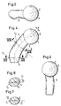
- FIGS. 4, 5, 6, 7 and 8 a collarless femoral neck prosthesis is shown, the ball center point 2 of which is likewise displaced medially by a distance B from the elongated center line 4.
- the center line 4 approaches the distal end in a slight curvature 6 and makes a slight bend 9 for the junction in the direction of the femoral axis.
- the distal end has an elliptical cross section, the major axis 11 of which lies in the frontal plane and passes laterally through a point P 1 . If one moves in Fig. 4 from this cross section along the curved center line 4 by an angle ⁇ of 45 ° upwards, there is again an elliptical, somewhat larger cross section (Fig.
- the curvature of the shaft is not only in the frontal plane and there is an anteversion for the ball head 1.
- the modulus of elasticity for the shaft is also between 10 and 60 GPa.
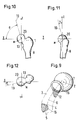
- phantom lines indicate the spatial position of a first contact surface 12 and a second contact surface 15, which are provided particularly close to or adjacent to the cortex.
- the bone bed is carefully prepared in these areas.
- the first contact surface 12 is proximally adjacent to the collar 16 against the medial and, when developed, approximately forms a triangular surface.
- the second contact surface 15 is arranged laterally at the distal shaft end and has the shape of a plaster which does not completely enclose the shaft at 180 °. It is conceivable to keep the modulus of elasticity somewhat higher in the area of these contact surfaces than on the rest of the shaft surface.
- the contact surfaces 12, 15 can have an expansion of 150 to 450 mm 2 .
- the material of the shaft can be plastics, as in the previous table are listed by powder or fiber of a other materials are increased in their modulus of elasticity.
- a higher melting point than the base material have approximately the same modulus of elasticity, increase the total modulus of elasticity can, if they are dispersed.
- 13 is one Femoral neck prosthesis shown, the shaft 3 and head 1 in one piece from the same material, for example made of plastic with powdered fillers is made.
- the actual storage area on the ball head is one Protective layer covered, so no fillers directly in the surface protrude. Manufacturing can be done by thermoplastic injection molding and Rework on the ball head.
- the ball head 1 consists of a Ceramic ball 23 with a cavity into which the shaft 3 with a extending pin 25 protrudes.
- the contact surface between pin 25 and the ceramic ball 23 is for securing with projections and recesses Mistake.
- the head 1 also consists of a different material with a higher modulus of elasticity than the shaft 3 having.
- the shaft 3 protrudes from the head 1 a pin 25 along the Center line into the shaft for better power transmission between Effect head and shaft.
- Fig. 17 two areas are recorded for the invention.
- a second preferred range for mostly short femoral neck prostheses with a length L between 55 and 100 mm and with a modulus of elasticity between 10 and 60 GPa gives equivalent stiffnesses between 0.55 ⁇ 10 9 and 6 ⁇ 10 9 [Newtons / meter].
- the normal 19 shows the resection plane, which by the center M of a natural and to be replaced Femoral head 20 is drawn as a resection cut can be considered a favorable for power transmission Record collar.
- the normal 19 is in the frontal plane (Fig. 10) in an angle ⁇ of 87 ° ⁇ 3 ° to the X axis, in the sagital plane (Fig. 11) in an angle ⁇ of 15 ° ⁇ 3 ° to the Z axis and in the transverse plane (Fig. 12) at an angle ⁇ of 13 ° ⁇ 3 ° to the X axis.
- the correct position for the resection cut can first be made with a pilot hole by the femoral head 20, the position of the normals 19 are determined and then the height at the femoral neck for a resection cut vertically can be determined to the identified normals 19.
- the forward midline of the femur occurs distally between the condyles out of the bone at one point. Cut in the proximal femur The midline of the femur and the femoral neck axis approximately in another point. A straight line is laid through these two points, which as Longitudinal axis of the femur or femoral axis is referred to. It is also the one proximally oriented + z-axis of the coordinate system.
- the exit point in the condylar region becomes a parallel to the knee joint axis placed.
- the knee axis is defined by the center points of the in the Sagittal plane approximately semicircular dorsal condylar portions Are defined.
- Shifted knee joint axis and femur axis span the frontal plane of the femur.
- the medial is perpendicular to + z directed + x-axis of the coordinate system, which is not exactly parallel to Knee axis is.
- the + y-axis is defined perpendicular to + x and + z.
- Your positive direction points forward for the left and right hip joint. Left there is therefore a right-handed, orthogonal coordinate system on which on the right hand side, however, a left-turning one.
- (x y) lies the Transverse plane of the bone fixed and (y z) defines the sagittal plane ".
Landscapes
- Health & Medical Sciences (AREA)
- Orthopedic Medicine & Surgery (AREA)
- Cardiology (AREA)
- Oral & Maxillofacial Surgery (AREA)
- Transplantation (AREA)
- Engineering & Computer Science (AREA)
- Biomedical Technology (AREA)
- Heart & Thoracic Surgery (AREA)
- Vascular Medicine (AREA)
- Life Sciences & Earth Sciences (AREA)
- Animal Behavior & Ethology (AREA)
- General Health & Medical Sciences (AREA)
- Public Health (AREA)
- Veterinary Medicine (AREA)
- Prostheses (AREA)
- Materials For Medical Uses (AREA)
Abstract
Description
| Material | Zugfestigkeit (MPa) | E-Modul (GPa) |
| PEEK (Polyetheretherketon) | 93,8 | 3,5 |
| PEI (Polyetherimid) | 105 | 3,0 |
| PET (Polyethylenerephthalat) | 159 | 8,96 |
| PPS (Polyphenylensulfid) | 138 | 11,7 |
| PAEK (Polyaryletherketon) | 121 | 9,0 |
- Fig. 1
- Schematisch eine Ansicht von anterior auf eine erfindungsgemässe, in der Frontalebene abgebildete Prothese in einem Femurknochen;
- Fig. 2
- schematisch die Prothese der Fig. 1 von proximal gesehen;
- Fig. 3
- schematisch die Prothese der Fig. 1 von lateral gesehen;
- Fig. 4
- schematisch ein weiteres Ausführungsbeispiel einer Femurhalsprothese ohne Kragen von anterior gesehen;
- Fig. 5
- schematisch die Prothese von Fig. 4 von proximal gesehen;
- Fig. 6
- schematisch die Prothese von Fig. 4 von medial gesehen;
- Fig. 7
- schematisch einen Schnitt VII-VII in Fig. 4;
- Fig. 8
- schematisch einen Schnitt VIII-VIII in Fig. 4;
- Fig. 9
- schematisch eine Ansicht von anterior und lateral auf eine Prothese analog zu Fig. 1, auf der erste und zweite Kontaktflächen eingezeichnet sind;
- Fig. 10
- schematisch in der Frontalebene von anterior die bevorzugte Winkellage für die Ebene des Kragens einer linken Femurhalsprothese mit Kragenauflage, dargestellt durch eine Normale, die durch den Mittelpunkt eines natürlichen Femurkopfes geht;
- Fig. 11
- schematisch die Normale von Fig. 10 in ihrer Projektion auf eine sagittale Ebene von lateral gesehen;
- Fig. 12
- schematisch die Normale von Fig. 10 in ihrer Projektion auf eine transversale Ebene von proximal gesehen;
- Fig. 13
- schematisch einen Längsschnitt in der Frontalebene durch eine Femurkopfprothese, bei der Kopf und Schaft ein gleiches Polymer aufweisen;
- Fig. 14
- schematisch einen Längsschnitt durch eine Prothese analog zu Fig. 13, bei welcher die Lagerfläche des Kopfes durch eine metallische Hohlkugel gebildet ist;
- Fig. 15
- schematisch einen Längsschnitt durch eine Prothese analog zu Fig. 13, bei welcher der Schaft zur Verankerung in den kugelförmigen Kopf hineinragt;
- Fig. 16
- schematisch einen Längsschnitt durch eine Prothese analog zu Fig. 13, bei welcher der kugelförmige Kopf zur Verankerung mit einer Verlängerung in den Schaft hineinragt; und
- Fig. 17
- schematisch eine Grafik in der E-Modul und Prothesenlänge L sowie die mit der Erfindung bevorzugten Bereiche aufgetragen sind.
Claims (15)
- Femurhalsprothese mit einem kugelförmigen Kopf (1), durch den ein Kugelmittelpunkt (2) definiert ist, und mit einem Schaft (3), welcher sich von der Höhe des Kugelmittelpunktes (2) entlang einer Mittellinie (4) über eine Länge L bis zu einem distalen Ende (5) erstreckt, dadurch gekennzeichnet, dass der Schaft einen Elastizitätsmodul E zwischen 10 GPa und 60 GPa aufweist, dass die Länge L zwischen 50 mm und 150 mm liegt, und dass die aus dem Produkt von Elastizitätsmodul E und Länge L gebildete Ersatzsteifigkeit S = E ·L zwischen 0,5 · 109 und 9 · 109 [Newton/Meter] liegt.
- Femurhalsprothese nach Anspruch 1, dadurch gekennzeichnet, dass die Mittellinie (4) des Schaftes (3) eine Krümmung (6) aufweist.
- Femurhalsprothese nach einem der Ansprüche 1 oder 2, dadurch gekennzeichnet, dass der Schaft (3) an seinem Ende (5) gegen abwärts in der Richtung der Längsachse (7) eines Femurknochens (8) einen Knick (9) aufweist.
- Femurhalsprothese nach einem der Ansprüche 1 bis 3, dadurch gekennzeichnet, dass der Schaft (3) senkrecht zur Mittellinie (4) bis zu seinem distalen Ende (5) elliptische Querschnitte (10) aufweist, deren Fläche mit der Annäherung an distal abnimmt.
- Femurhalsprothese nach Anspruch 4, dadurch gekennzeichnet, dass die grossen Achsen (11) der elliptischen Querschnitte (10) mit der Verschiebung von proximal gegen distal eine Drehung um einen Verdrehwinkel ε ≤ 8° durchführen.
- Femurhalsprothese nach einem der Ansprüche 1 bis 5, dadurch gekennzeichnet, dass unterhalb des Kopfes (1) medial am Schaft (3) eine in der Abwicklung ungefähr als Dreieck ausgebildete erste Kontaktfläche (12) für die Kortikalis eines reserzierten Femurhalses (13) vorgesehen ist und dass für den Bereich des Femurmarkraumes (14) lateral am Schaft (3) eine zweite Kontaktfläche (15) für die Kortikalis des Femurknochens (8) vorgesehen ist, um ein Kippmoment des Schaftes (3) an den Knochen (13, 8) zu übergeben.
- Femurkopfprothese nach Anspruch 6, dadurch gekennzeichnet, dass die erste und zweite Kontaktfläche (12, 15) jeweils einer Fläche von 150 mm2 bis 450 mm2 entsprechen.
- Femurkopfprothese nach einem der Ansprüche 1 bis 7, dadurch gekennzeichnet, dass der Schaft (3) zum Kopf (1) hin einen Kragen (16) aufweist.
- Femurkopfprothese nach Anspruch 8, dadurch gekennzeichnet, dass der Kragen (16) in einer Ebene (18) liegt, der eine bestimmte Lage zugeordnet ist, derart, dass die Ebene (18) mit ihrer Normalen (19) in der Projektion auf die Frontalebene zu einer gegen medial verlaufenden, horizontalen X-Achse einen Winkel α = 87°, in der Projektion auf die Sagittalebene mit der vertikalen Z-Achse einen Winkel β = 15° und in der Projektion auf die Transversalebene mit der gegen medial verlaufenden, horizontalen X-Achse einen Winkel γ = 13° bildet, wobei die Winkelangaben um plus/minus 3° streuen dürfen.
- Femurkopfprothese nach einem der Ansprüche 1 bis 9, dadurch gekennzeichnet, dass Kopf (1) und Schaft (3) aus unterschiedlichen Werkstoffen bestehen.
- Femurkopfprothese nach Anspruch 10, dadurch gekennzeichnet, dass jeweils Kopf (1) und Schaft (3) aus einem nicht-metallischen Werkstoff bestehen.
- Femurkopfprothese nach Anspruch 11, dadurch gekennzeichnet, dass der Kopf (1) aus einem keramischen Werkstoff besteht.
- Femurkopfprothese nach Anspruch 10, dadurch gekennzeichnet, dass der Kopf (1) als hohle Metallkugel ausgeführt ist, in welche ein Schaft (3) aus Kunststoff eingeformt ist.
- Femurkopfprothese nach Anspruch 10, dadurch gekennzeichnet, dass der Kopf (1) eine Verlängerung (17) aufweist, an welche ein Schaft (3) angeformt ist.
- Femurkopfprothese nach einem der vorangehenden Ansprüche, dadurch gekennzeichnet, dass der Schaft (3) durch Fasermaterial oder Füllstoffe verstärkt ist, um den E-Modul auf einen gewünschten Wert zu bringen.
Priority Applications (4)
| Application Number | Priority Date | Filing Date | Title |
|---|---|---|---|
| AT01810866T ATE376817T1 (de) | 2001-09-10 | 2001-09-10 | Femurhalsprothese |
| EP01810866A EP1290991B1 (de) | 2001-09-10 | 2001-09-10 | Femurhalsprothese |
| DE50113196T DE50113196D1 (de) | 2001-09-10 | 2001-09-10 | Femurhalsprothese |
| US10/235,232 US20030074083A1 (en) | 2001-09-10 | 2002-09-05 | Femoral neck prosthesis |
Applications Claiming Priority (1)
| Application Number | Priority Date | Filing Date | Title |
|---|---|---|---|
| EP01810866A EP1290991B1 (de) | 2001-09-10 | 2001-09-10 | Femurhalsprothese |
Publications (2)
| Publication Number | Publication Date |
|---|---|
| EP1290991A1 true EP1290991A1 (de) | 2003-03-12 |
| EP1290991B1 EP1290991B1 (de) | 2007-10-31 |
Family
ID=8184127
Family Applications (1)
| Application Number | Title | Priority Date | Filing Date |
|---|---|---|---|
| EP01810866A Expired - Lifetime EP1290991B1 (de) | 2001-09-10 | 2001-09-10 | Femurhalsprothese |
Country Status (4)
| Country | Link |
|---|---|
| US (1) | US20030074083A1 (de) |
| EP (1) | EP1290991B1 (de) |
| AT (1) | ATE376817T1 (de) |
| DE (1) | DE50113196D1 (de) |
Cited By (1)
| Publication number | Priority date | Publication date | Assignee | Title |
|---|---|---|---|---|
| US8152855B2 (en) | 2006-11-03 | 2012-04-10 | Howmedica Osteonics Corp. | Method and apparatus for hip femoral resurfacing tooling |
Families Citing this family (19)
| Publication number | Priority date | Publication date | Assignee | Title |
|---|---|---|---|---|
| US7534271B2 (en) | 2004-01-22 | 2009-05-19 | Smith + Nephew | Femoral hip prosthesis and method of implantation |
| US20080220039A1 (en) * | 2004-09-17 | 2008-09-11 | Sherman Darren R | Thin Film Medical Devices Manufactured on Application Specific Core Shapes |
| GB2419291A (en) * | 2004-10-21 | 2006-04-26 | Biomet Uk Ltd | A femoral head prosthesis |
| DE102007031667A1 (de) * | 2006-08-04 | 2008-02-14 | Ceramtec Ag Innovative Ceramic Engineering | Einfügen von schwingungsdämpfenden Elementen in Prothesensysteme zur Manipulation und Dämpfung der Eigenfrequenzen |
| US8974540B2 (en) * | 2006-12-07 | 2015-03-10 | Ihip Surgical, Llc | Method and apparatus for attachment in a modular hip replacement or fracture fixation device |
| US8579985B2 (en) | 2006-12-07 | 2013-11-12 | Ihip Surgical, Llc | Method and apparatus for hip replacement |
| WO2008069800A1 (en) | 2006-12-07 | 2008-06-12 | Anatol Podolsky | Method and apparatus for total hip replacement |
| FR2928829B1 (fr) * | 2008-03-21 | 2011-07-08 | Tornier Sa | Implant articulaire comportant une surface de contact en carbone pyrolytique et une piece de fixation obtenue par surmoulage |
| US8052755B2 (en) * | 2008-05-09 | 2011-11-08 | Remi Sciences, Inc. | Ulnar head prosthesis system |
| JP2012525942A (ja) * | 2009-05-07 | 2012-10-25 | スミス アンド ネフュー インコーポレーテッド | モジュール式試行プロテーゼヘッド |
| IT1403668B1 (it) * | 2011-02-01 | 2013-10-31 | Ala Ortho S R L | Stelo femorale per protesi dell'anca. |
| US9301765B2 (en) | 2011-12-16 | 2016-04-05 | Chow Ip, Llc | Prosthetic femoral stem for use in high offset hip replacement |
| US8992531B2 (en) | 2011-12-16 | 2015-03-31 | Chow Ip, Llc | Prosthetic femoral stem for use in high impact hip replacement |
| FR3021524A1 (fr) * | 2014-06-02 | 2015-12-04 | Small Bone Innovations Internat | Tige d'ancrage metacarpien, notamment pour une prothese trapezo-metacarpienne |
| USD895116S1 (en) * | 2017-11-15 | 2020-09-01 | Joint Innovation Technology, Llc | Revision stem and cup |
| JP1621250S (de) * | 2017-05-22 | 2018-12-25 | ||
| USD900317S1 (en) * | 2017-11-15 | 2020-10-27 | Joint Innovation Technology, Llc | Revision stem |
| USD891615S1 (en) * | 2017-11-15 | 2020-07-28 | Joint Innovation Technogy, Llc | Revision stem |
| USD881395S1 (en) * | 2017-11-15 | 2020-04-14 | Joint Innovation Technology, Llc | Revision stem and ball |
Citations (4)
| Publication number | Priority date | Publication date | Assignee | Title |
|---|---|---|---|---|
| DE2621123A1 (de) * | 1976-05-13 | 1977-11-24 | Sigri Elektrographit Gmbh | Gelenkprothese |
| EP0019044A1 (de) * | 1979-05-19 | 1980-11-26 | Sigri Elektrographit Gmbh | Schaftteil einer Hüftgelenkendoprothese und Verfahren zur Herstellung desselben |
| EP0420435A2 (de) * | 1989-09-28 | 1991-04-03 | Imperial Chemical Industries Plc | Prothesenvorrichtung |
| US6120544A (en) * | 1997-05-16 | 2000-09-19 | Eska Implants Gmbh & Co. | Femur endoprosthesis for articial hip joint |
-
2001
- 2001-09-10 DE DE50113196T patent/DE50113196D1/de not_active Expired - Lifetime
- 2001-09-10 EP EP01810866A patent/EP1290991B1/de not_active Expired - Lifetime
- 2001-09-10 AT AT01810866T patent/ATE376817T1/de not_active IP Right Cessation
-
2002
- 2002-09-05 US US10/235,232 patent/US20030074083A1/en not_active Abandoned
Patent Citations (4)
| Publication number | Priority date | Publication date | Assignee | Title |
|---|---|---|---|---|
| DE2621123A1 (de) * | 1976-05-13 | 1977-11-24 | Sigri Elektrographit Gmbh | Gelenkprothese |
| EP0019044A1 (de) * | 1979-05-19 | 1980-11-26 | Sigri Elektrographit Gmbh | Schaftteil einer Hüftgelenkendoprothese und Verfahren zur Herstellung desselben |
| EP0420435A2 (de) * | 1989-09-28 | 1991-04-03 | Imperial Chemical Industries Plc | Prothesenvorrichtung |
| US6120544A (en) * | 1997-05-16 | 2000-09-19 | Eska Implants Gmbh & Co. | Femur endoprosthesis for articial hip joint |
Cited By (1)
| Publication number | Priority date | Publication date | Assignee | Title |
|---|---|---|---|---|
| US8152855B2 (en) | 2006-11-03 | 2012-04-10 | Howmedica Osteonics Corp. | Method and apparatus for hip femoral resurfacing tooling |
Also Published As
| Publication number | Publication date |
|---|---|
| DE50113196D1 (de) | 2007-12-13 |
| ATE376817T1 (de) | 2007-11-15 |
| EP1290991B1 (de) | 2007-10-31 |
| US20030074083A1 (en) | 2003-04-17 |
Similar Documents
| Publication | Publication Date | Title |
|---|---|---|
| EP1290991B1 (de) | Femurhalsprothese | |
| DE60132873T2 (de) | Prothesenlagerbauteil | |
| DE3689260T2 (de) | Femurkopf-prothese. | |
| DE69331586T2 (de) | Verbessertes femorales manschettenimplantat | |
| EP0135755B1 (de) | Schaft für eine Hüftgelenkprothese | |
| DE68922487T2 (de) | Prothesengelenk. | |
| EP0058745B1 (de) | Gerader, blattartiger Schaft für eine Gelenkendoprothese | |
| EP0971651B1 (de) | Hüftgelenkendoprothese | |
| EP0366603B1 (de) | Blattartiger Schaft aus Metall für eine Femurkopfprothese | |
| DE69228190T2 (de) | Femorales hüftimplantat mit verringerter steifheit | |
| DE69425015T2 (de) | Femurkomponente für eine Hüftprothese | |
| EP0069252B1 (de) | Gelenkendoprothese | |
| CH637536A5 (de) | Femurkomponente einer hueftendoprothese. | |
| EP0404716B1 (de) | Verankerungsschaft für eine Femurkopfprothese | |
| EP0119394B1 (de) | Femurteil für eine Kniegelenkprothese | |
| DE2931750C2 (de) | Einteiliges Oberschenkelteil einer Hüftgelenkendoprothese | |
| DE2517702C3 (de) | Femurteil einer Hüftgelenktotalendoprothese | |
| WO2008080595A2 (de) | Hüftgelenkprothese | |
| DE10212982A1 (de) | Verfahren zum Implantieren von Hüftgelenkendoprothesen und entsprechende Endoprothese | |
| DE19820748A1 (de) | Gelenkersatz an Grundgelenken von Fingern und Zehen | |
| EP1357864B1 (de) | Schenkelhalsendoprothese für ein künstliches hüftgelenk | |
| DE20302180U1 (de) | Implantat | |
| WO2005089677A1 (de) | Femur- oder humeruskomponente einer kugelgelenks-endoprothese mit dämpfungselement | |
| DE102021107086A1 (de) | Spongioser Endoprothesenschaft | |
| DE20109207U1 (de) | Femurteil für eine Hüftgelenkendoprothese |
Legal Events
| Date | Code | Title | Description |
|---|---|---|---|
| PUAI | Public reference made under article 153(3) epc to a published international application that has entered the european phase |
Free format text: ORIGINAL CODE: 0009012 |
|
| AK | Designated contracting states |
Designated state(s): AT BE CH CY DE DK ES FI FR GB GR IE IT LI LU MC NL PT SE TR Kind code of ref document: A1 Designated state(s): AT BE CH CY DE DK ES FI FR GB GR IE IT LI LU MC NL PT SE TR |
|
| AX | Request for extension of the european patent |
Extension state: AL LT LV MK RO SI |
|
| 17P | Request for examination filed |
Effective date: 20030404 |
|
| AKX | Designation fees paid |
Designated state(s): AT CH DE FR GB IT LI |
|
| RAP1 | Party data changed (applicant data changed or rights of an application transferred) |
Owner name: ZIMMER GMBH |
|
| GRAP | Despatch of communication of intention to grant a patent |
Free format text: ORIGINAL CODE: EPIDOSNIGR1 |
|
| GRAS | Grant fee paid |
Free format text: ORIGINAL CODE: EPIDOSNIGR3 |
|
| GRAA | (expected) grant |
Free format text: ORIGINAL CODE: 0009210 |
|
| AK | Designated contracting states |
Kind code of ref document: B1 Designated state(s): AT CH DE FR GB IT LI |
|
| REG | Reference to a national code |
Ref country code: GB Ref legal event code: FG4D Free format text: NOT ENGLISH |
|
| REG | Reference to a national code |
Ref country code: CH Ref legal event code: EP |
|
| REF | Corresponds to: |
Ref document number: 50113196 Country of ref document: DE Date of ref document: 20071213 Kind code of ref document: P |
|
| GBT | Gb: translation of ep patent filed (gb section 77(6)(a)/1977) |
Effective date: 20071212 |
|
| ET | Fr: translation filed | ||
| PLBE | No opposition filed within time limit |
Free format text: ORIGINAL CODE: 0009261 |
|
| STAA | Information on the status of an ep patent application or granted ep patent |
Free format text: STATUS: NO OPPOSITION FILED WITHIN TIME LIMIT |
|
| 26N | No opposition filed |
Effective date: 20080801 |
|
| PGFP | Annual fee paid to national office [announced via postgrant information from national office to epo] |
Ref country code: AT Payment date: 20080915 Year of fee payment: 8 |
|
| PG25 | Lapsed in a contracting state [announced via postgrant information from national office to epo] |
Ref country code: AT Free format text: LAPSE BECAUSE OF NON-PAYMENT OF DUE FEES Effective date: 20090910 |
|
| PGFP | Annual fee paid to national office [announced via postgrant information from national office to epo] |
Ref country code: IT Payment date: 20100924 Year of fee payment: 10 Ref country code: FR Payment date: 20101005 Year of fee payment: 10 |
|
| PGFP | Annual fee paid to national office [announced via postgrant information from national office to epo] |
Ref country code: GB Payment date: 20100921 Year of fee payment: 10 |
|
| GBPC | Gb: european patent ceased through non-payment of renewal fee |
Effective date: 20110910 |
|
| PG25 | Lapsed in a contracting state [announced via postgrant information from national office to epo] |
Ref country code: IT Free format text: LAPSE BECAUSE OF NON-PAYMENT OF DUE FEES Effective date: 20110910 |
|
| REG | Reference to a national code |
Ref country code: FR Ref legal event code: ST Effective date: 20120531 |
|
| PG25 | Lapsed in a contracting state [announced via postgrant information from national office to epo] |
Ref country code: GB Free format text: LAPSE BECAUSE OF NON-PAYMENT OF DUE FEES Effective date: 20110910 Ref country code: FR Free format text: LAPSE BECAUSE OF NON-PAYMENT OF DUE FEES Effective date: 20110930 |
|
| REG | Reference to a national code |
Ref country code: CH Ref legal event code: NV Representative=s name: DR. GRAF AND PARTNER AG INTELLECTUAL PROPERTY, CH |
|
| PGFP | Annual fee paid to national office [announced via postgrant information from national office to epo] |
Ref country code: CH Payment date: 20170912 Year of fee payment: 17 Ref country code: DE Payment date: 20170905 Year of fee payment: 17 |
|
| REG | Reference to a national code |
Ref country code: DE Ref legal event code: R119 Ref document number: 50113196 Country of ref document: DE |
|
| REG | Reference to a national code |
Ref country code: CH Ref legal event code: PL |
|
| PG25 | Lapsed in a contracting state [announced via postgrant information from national office to epo] |
Ref country code: DE Free format text: LAPSE BECAUSE OF NON-PAYMENT OF DUE FEES Effective date: 20190402 |
|
| PG25 | Lapsed in a contracting state [announced via postgrant information from national office to epo] |
Ref country code: CH Free format text: LAPSE BECAUSE OF NON-PAYMENT OF DUE FEES Effective date: 20180930 Ref country code: LI Free format text: LAPSE BECAUSE OF NON-PAYMENT OF DUE FEES Effective date: 20180930 |