EP1290848B1 - Ip address allocation in a mobile telecommunications network - Google Patents
Ip address allocation in a mobile telecommunications network Download PDFInfo
- Publication number
- EP1290848B1 EP1290848B1 EP01929651A EP01929651A EP1290848B1 EP 1290848 B1 EP1290848 B1 EP 1290848B1 EP 01929651 A EP01929651 A EP 01929651A EP 01929651 A EP01929651 A EP 01929651A EP 1290848 B1 EP1290848 B1 EP 1290848B1
- Authority
- EP
- European Patent Office
- Prior art keywords
- address
- new
- srns
- srns relocation
- identity
- Prior art date
- Legal status (The legal status is an assumption and is not a legal conclusion. Google has not performed a legal analysis and makes no representation as to the accuracy of the status listed.)
- Expired - Lifetime
Links
- 238000000034 method Methods 0.000 claims abstract description 56
- 230000004913 activation Effects 0.000 claims description 22
- 238000012545 processing Methods 0.000 claims description 4
- 101710204139 Acyl carrier protein 2 Proteins 0.000 description 5
- 101710113789 Candidapepsin-2 Proteins 0.000 description 5
- 230000011664 signaling Effects 0.000 description 5
- 101710204136 Acyl carrier protein 1 Proteins 0.000 description 4
- 101710113788 Candidapepsin-1 Proteins 0.000 description 4
- 238000010586 diagram Methods 0.000 description 4
- 230000005540 biological transmission Effects 0.000 description 2
- 238000013507 mapping Methods 0.000 description 2
- 238000013459 approach Methods 0.000 description 1
- 238000004891 communication Methods 0.000 description 1
- 230000003111 delayed effect Effects 0.000 description 1
- 230000000694 effects Effects 0.000 description 1
- 238000012986 modification Methods 0.000 description 1
- 230000004048 modification Effects 0.000 description 1
- 230000002035 prolonged effect Effects 0.000 description 1
- 238000012546 transfer Methods 0.000 description 1
Images


Classifications
-
- H—ELECTRICITY
- H04—ELECTRIC COMMUNICATION TECHNIQUE
- H04W—WIRELESS COMMUNICATION NETWORKS
- H04W36/00—Hand-off or reselection arrangements
- H04W36/0005—Control or signalling for completing the hand-off
- H04W36/0011—Control or signalling for completing the hand-off for data sessions of end-to-end connection
-
- H—ELECTRICITY
- H04—ELECTRIC COMMUNICATION TECHNIQUE
- H04L—TRANSMISSION OF DIGITAL INFORMATION, e.g. TELEGRAPHIC COMMUNICATION
- H04L61/00—Network arrangements, protocols or services for addressing or naming
- H04L61/50—Address allocation
- H04L61/5007—Internet protocol [IP] addresses
-
- H—ELECTRICITY
- H04—ELECTRIC COMMUNICATION TECHNIQUE
- H04L—TRANSMISSION OF DIGITAL INFORMATION, e.g. TELEGRAPHIC COMMUNICATION
- H04L61/00—Network arrangements, protocols or services for addressing or naming
- H04L61/50—Address allocation
- H04L61/5061—Pools of addresses
-
- H—ELECTRICITY
- H04—ELECTRIC COMMUNICATION TECHNIQUE
- H04L—TRANSMISSION OF DIGITAL INFORMATION, e.g. TELEGRAPHIC COMMUNICATION
- H04L61/00—Network arrangements, protocols or services for addressing or naming
- H04L61/50—Address allocation
- H04L61/5076—Update or notification mechanisms, e.g. DynDNS
-
- H—ELECTRICITY
- H04—ELECTRIC COMMUNICATION TECHNIQUE
- H04L—TRANSMISSION OF DIGITAL INFORMATION, e.g. TELEGRAPHIC COMMUNICATION
- H04L61/00—Network arrangements, protocols or services for addressing or naming
- H04L61/50—Address allocation
- H04L61/5084—Providing for device mobility
-
- H—ELECTRICITY
- H04—ELECTRIC COMMUNICATION TECHNIQUE
- H04L—TRANSMISSION OF DIGITAL INFORMATION, e.g. TELEGRAPHIC COMMUNICATION
- H04L61/00—Network arrangements, protocols or services for addressing or naming
- H04L61/50—Address allocation
- H04L61/5092—Address allocation by self-assignment, e.g. picking addresses at random and testing if they are already in use
-
- H—ELECTRICITY
- H04—ELECTRIC COMMUNICATION TECHNIQUE
- H04W—WIRELESS COMMUNICATION NETWORKS
- H04W36/00—Hand-off or reselection arrangements
- H04W36/12—Reselecting a serving backbone network switching or routing node
-
- H—ELECTRICITY
- H04—ELECTRIC COMMUNICATION TECHNIQUE
- H04W—WIRELESS COMMUNICATION NETWORKS
- H04W80/00—Wireless network protocols or protocol adaptations to wireless operation
- H04W80/04—Network layer protocols, e.g. mobile IP [Internet Protocol]
Definitions
- the present invention relates to IP address allocation in a mobile telecommunications network and more particularly to IP address changing such as occurs during a Serving Radio Network Subsystem relocation procedure.
- Each RNC 5 forms part of a Radio Network Subsystem (RNSs) 7,8 which also comprises a set of Base Transceiver Stations 9 referred to in UMTS terminology as Node B's.
- the interface between a RNC 5,6 and a Node B 9 is known as the Iub interface.
- a Node B 9 provides the connection point to the UTRAN 4 for a UE 3, and the interface between the Node B 9 and the UE 3 is known as the Uu interface.
- the RNS (for example RNS 7 in Figure 1 ) which connects a UE 3 to the core network 1 at any given time is referred to as the Serving RNS (SRNS) for that particular UE 3, whilst the RNC 6 of the SRNS 7 is known as the Serving RNC (SRNC).
- SRNS Serving RNS
- SRNC Serving RNC
- the SRNC is in charge of the radio connection between the UE 3 and the UTRAN 4 and the SRNC 6 terminates the Iu protocols for the UE 3.
- a so-called "Drift" RNC (DRNC) may support a SRNC with additional radio resources when the connection between the UTRAN and the UE requires the use of Node Bs controlled by the DRNC.
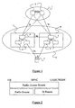
- FIG. 2 illustrates in very general terms the bearer structure used by UTRAN to carry user data between the UE 3 and the core network 1.
- the responsible UMSC or SGSN 2 instructs the UTRAN 4 to establish a logical connection between the UMSC or SGSN 2 and the UE 3.
- This logical connection is referred to as a Radio Access Bearer (RAB).
- RAB Radio Access Bearer
- the established RAB inherits requirements of the requested UMTS service, e.g. Quality of Service, etc.
- the SRNC 6 establishes user plane connections with the core network 1 (i.e. UMSC or SGSN 2) and with the UE 3.
- the connection between the SRNC 6 and the core network 1 is referred to as the Iu bearer whilst the connection between the SRNC 6 and the UE 3 is referred to as the Radio Bearer (RB).
- Both of these bearers represent further logical channels, with the SRNC 6 performing a mapping between them.
- the bearers themselves are mapped onto appropriate traffic channels for transmission over the respective interfaces (Iu and Uu).
- a single UE 3 may be associated with one or more RABs.
- a UE 3 may simultaneously make use of one RAB established for a voice call, and another RAB established for a data call.
- An RNC 5,6 uses RAB identifiers to distinguish between these different RABs.
- a RB identity is used to distinguish between RBs.
- a RAB and a RB are implicitly associated with one another by the RNC.
- the RB Whilst the Iu bearer associated with a RAB always extends between the UMSC/SGSN 2 and the SRNS 7, the RB may extend directly between the SRNS 7 and the UE 3 or between the SRNS 7 and the UE 3 via a DRNS (such as the RNS 8 in Figure 1 ). In the latter case, the RB is said to have multiple legs. In some circumstances, RBs may simultaneously exist directly between the SRNS 7 and the UE 3 and indirectly via a DRNS 8.
- SRNS relocation in which an existing SRNS is replaced by a "target" RNS. This might arise, for example, where a UE moves to an extent that it is no longer able to use any of the Base Stations controlled by the current SRNS.
- control of the radio resources may be transferred from the current SRNS to a new RNS.
- a RB is already established between a UE and a Drift RNS, it may be appropriate to make the DRNS the SRNS, for example to optimise the connection to the core network (such that the DRNS becomes the target RNS).
- the SRNS relocation process may be initiated by the Serving RNC sending to the core network (UMSC or SGSN) a Relocation Required message.
- This message is currently defined in the Radio Access Network Application Part (RANAP) protocol (UMTS TS 25.413) and carried over the Iu interface.
- RANAP Radio Access Network Application Part
- the core network responds to receipt of a Relocation Required message by sending a Revocation Request message to the target RNC (of the target RNS).
- the Relocation Request message is also defined in the RANAP protocol.
- the Relocation Request message contains the identities of the RABs to be transferred. Both the Relocation Request message and the Relocation Required message contain an RRC Initialisation Information container. This container is defined in the Radio Resource Control (RRC) protocol (UMTS TS 25.331), and contains amongst other things the identities of the RBs to be transferred as well as details of the mappings between the RBs and the lower layer attributes, i.e. to logical, transport, and physical channels.
- RRC Radio Resource Control
- IP Internet Protocol
- a subscriber i.e. UE 3 in Figure 1
- a subscriber i.e. UE 3 in Figure 1
- DIA Direct Internet Access
- Other proposals for allocating IP addresses include the provision in the UTRAN 4 of specialised nodes known as Access Control Points (ACPs) - a specialised Media Gateway Controller - which are responsible for mobility management and session management operations such as IP address allocation.
- ACPs Access Control Points
- ACPs Access Control Points
- Media Gateway Controller specialised Media Gateway Controller
- IPv4 IP address allocation
- Any mobile IP system must take into account the possibility that subscribers may roam within a given network and between networks (as outlined above).
- a protocol such as Mobile IP may be used to allow datagrams directed to a previous SRNC to be forwarded to the current SRNC.
- EP 0 883 266 discloses a router device, datagram transfer method and communication system for hand-off control for mobile terminals.
- EP 0 967 769 discloses a technique for updating the address of wireless mobile terminal hosts affiliated with a wired network.
- WO 99/41927 discloses a system for changing the service profile of a mobile subscriber. In this document the mobile station figures out whether and when the connection to the network should be exchanged, and acts accordingly.
- SRNS relocation requires a new IP address to be negotiated between the UE and the new SRNS following the SRNS relocation process. Only after an IP address has been allocated can the UE issue a Binding Update to its Home Agent and correspondent hosts. This results in a prolonged period during which packets received from a correspondent host will be routed to the old SRNS and tunnelled to the new SRNS. Datagrams may be delayed and/or lost in this tunnelling process. Whilst this may not be a significant problem for traditional IP uses (such as downloading data from a web server), it may interfere with certain real time applications such as IP telephony (Voice-Over-IP) and videoconferencing.
- IP telephony Voice-Over-IP
- Embodiments of the present invention provide a new IP address to a mobile UE which can be brought into use immediately after the SRNS relocation process is completed.
- a Binding update can be sent from the UE to the Home Agent and to correspondent hosts almost immediately. No significant disruption of an IP service should therefore occur.
- the present invention may be employed in association with either a hard handover or a soft handover, both of which may involve SRNS relocation. However, in some cases SRNS relocation may be carried out independently of a handover process.
- the invention applies to both the Direct Internet Access architecture and to other architectures where a new IP address is required as a result of SRNS relocation.
- the mobile telecommunications system is a Universal Mobile Telecommunications System (UMTS).
- UMTS Universal Mobile Telecommunications System
- the invention may also be employed in other systems.
- IP addresses may be allocated by the Serving or Target RNCs or by another network node, such as an Access Control Point (ACP).
- ACP Access Control Point
- the ACP may be integrated into the associated RNC or may be implemented as a separate node.
- said new IP address is sent from the current ACP to the UE prior to SRNS relocation.
- said new IP address may be sent to the UE from the target ACP.
- the UE is notified of an activation identity using which the UE is able to determine when to replace the previously used IP address with the new IP address as the in-use IP address.
- the activation identity is a Radio Resource identity (such as a SRNTI or SRNC identity) such that the new IP address is brought into use when the UE notices that the associated Radio Resource identity is active.
- the new IP address may be generated using the activation identity.
- the activation identity is an SRNTI
- this may form the host part of the new IP address.
- the step of notifying the UE of a new IP address may be carried out following the making of a decision, e.g. by the current SRNS, to perform SRNS relocation.
- the target RNS (or a node controlling the target RNS such as an ACP node) reserves a unique IP address for the UE and which is notified to the UE.
- the UE may be notified of a plurality of new IP addresses and respective activation identities, prior to one or more SRNS relocation processes.
- a mobile telecommunications system comprising means for notifying a mobile UE of a new IP address or means for generating a new IP address prior to carrying out a SRNS relocation process whereby control of the UE is transferred from a currently Serving Radio Network Subsystem (SRNS) to a Target RNS, the UE being arranged to replace the previously used IP address with the new IP address as the in-use IP address during said SRNS relocation process or immediately thereafter, characterized by means for notifying the UE, prior to said SRNS relocation taking place, but after it has been decided that a SRNS relocation is required, of an activation identity using which the UE is able to determine when to replace the previously used IP address with the new IP address as the in-use IP address.
- SRNS Radio Network Subsystem
- a mobile User Equipment comprising:
- Figures 3A to 3C illustrates a scenario in a UMTS network where SRNS (or SRNC) relocation arises.
- the network incorporates the Direct Internet Access (DIA) architecture described briefly above and in which the point of connection to the Internet for a particular mobile UE is the SRNC for that user (the SRNC being coupled to the DIA) architecture described briefly above and in which the point of connection to the Internet for a particular mobile UE is the SRNC for that user (the SRNC being coupled to the DIA) architecture described briefly above and in which the point of connection to the Internet for a particular mobile UE is the SRNC for that user (the SRNC being coupled to the DIA)
- IP address allocation is handled by respective Access Control Points (ACP 1 and ACP 2) coupled to the two RNCs.
- ACP 1 and ACP 2 are Access Control Points coupled to the two RNCs.
- a RB has been established between the UE and the SRNC and, it is assumed, an IP address allocated to the UE from the pool of IP addresses available to the SRNC. IP datagrams are conveyed over the established RB between the UE and the SRNC.
- FIG 3B the situation of Figure 3A has been modified such that an RB has been established between the SRNC and the UE via a Drift RNC (DRNC).
- DRNC Drift RNC
- UMTS provides for multiple RBs to exist simultaneously for a given UE in order, for example, to reduce the likelihood of data transmission errors (the same data may be sent simultaneously to and from the UE over two or more RBs).
- the SRNC remains in control of the radio resources allocated to the UB and importantly remains the node through which IP packets associated with the UE are routed. The IP address used in the situation of Figure 3A therefore continues to be used in the situation of Figure 3B .
- Figure 4 is a signalling diagram illustrating an IP address changing process which follows this decision. The six signalling steps involve:
- an activation identity which is sent to the UE as an intrinsic part of the relocation procedure or which is incorporated into the existing signalling structure avoids the need for an additional signalling message.
- an additional message may be used to activate a new IP address if necessary.
- FIGS 6A and 6B illustrates a hard handover scenario during which the present invention may be employed.
- the role of serving RNC for the UE is passed directly from a first to a second RNC.
- the UE Prior to handover, the UE is notified of a new IP address (or means for generating an IP address) such that the new IP address is available immediately following the handover.
Abstract
Description
- The present invention relates to IP address allocation in a mobile telecommunications network and more particularly to IP address changing such as occurs during a Serving Radio Network Subsystem relocation procedure.
-
Figure 1 illustrates schematically a part of a Universal Mobile Telecommunications System (UMTS) network. The network includes acore network part 1, which may be a network handling voice calls using UMTS Mobile Switching Centres (UMSCs) or may be a data network such as a General Packet Radio Service (GPRS) network including Serving GPRS Support Nodes (SGSN) or Gateway GPRS Support Nodes (GGSNs). InFigure 1 the UMSCs and SGSNs/GGSNs are indicated generally with thereference numeral 2. A subscriber or User Equipment (UE) 3 is coupled to thecore network 1 via anaccess network 4 referred to as a Universal Terrestrial Radio Access Network (UTRAN). More particularly, the UMSCs/SGSNs/GGSNs 2 are connected to Radio Network Controllers (RNCs) 5,6 of the UTRAN 4 over an interface referred to as the Iu interface. - Each
RNC 5 forms part of a Radio Network Subsystem (RNSs) 7,8 which also comprises a set of Base Transceiver Stations 9 referred to in UMTS terminology as Node B's. The interface between aRNC UE 3, and the interface between the Node B 9 and the UE 3 is known as the Uu interface. The RNS (forexample RNS 7 inFigure 1 ) which connects aUE 3 to thecore network 1 at any given time is referred to as the Serving RNS (SRNS) for thatparticular UE 3, whilst theRNC 6 of theSRNS 7 is known as the Serving RNC (SRNC). The SRNC is in charge of the radio connection between the UE 3 and the UTRAN 4 and the SRNC 6 terminates the Iu protocols for the UE 3. A so-called "Drift" RNC (DRNC) may support a SRNC with additional radio resources when the connection between the UTRAN and the UE requires the use of Node Bs controlled by the DRNC. -
Figure 2 illustrates in very general terms the bearer structure used by UTRAN to carry user data between the UE 3 and thecore network 1. When it is required to establish a user plane connection, the responsible UMSC or SGSN 2 instructs the UTRAN 4 to establish a logical connection between the UMSC or SGSN 2 and theUE 3. This logical connection is referred to as a Radio Access Bearer (RAB). The established RAB inherits requirements of the requested UMTS service, e.g. Quality of Service, etc. Based on the inherited requirements of the RAB, the SRNC 6 establishes user plane connections with the core network 1 (i.e. UMSC or SGSN 2) and with the UE 3. The connection between the SRNC 6 and thecore network 1 is referred to as the Iu bearer whilst the connection between the SRNC 6 and the UE 3 is referred to as the Radio Bearer (RB). Both of these bearers represent further logical channels, with the SRNC 6 performing a mapping between them. The bearers themselves are mapped onto appropriate traffic channels for transmission over the respective interfaces (Iu and Uu). - A
single UE 3 may be associated with one or more RABs. For example, a UE 3 may simultaneously make use of one RAB established for a voice call, and another RAB established for a data call. AnRNC SGSN 2 and theSRNS 7, the RB may extend directly between theSRNS 7 and theUE 3 or between theSRNS 7 and theUE 3 via a DRNS (such as theRNS 8 inFigure 1 ). In the latter case, the RB is said to have multiple legs. In some circumstances, RBs may simultaneously exist directly between the SRNS 7 and the UE 3 and indirectly via aDRNS 8. - An important feature of mobile telecommunication systems is the ability to allow subscribers to move within (and outside of) particular networks. This often requires a process known as SRNS relocation, in which an existing SRNS is replaced by a "target" RNS. This might arise, for example, where a UE moves to an extent that it is no longer able to use any of the Base Stations controlled by the current SRNS. In order to optimise the usage of resources, control of the radio resources may be transferred from the current SRNS to a new RNS. In situations where a RB is already established between a UE and a Drift RNS, it may be appropriate to make the DRNS the SRNS, for example to optimise the connection to the core network (such that the DRNS becomes the target RNS).
- In either of the above scenarios, the SRNS relocation process may be initiated by the Serving RNC sending to the core network (UMSC or SGSN) a Relocation Required message. This message is currently defined in the Radio Access Network Application Part (RANAP) protocol (UMTS TS 25.413) and carried over the Iu interface. The core network responds to receipt of a Relocation Required message by sending a Revocation Request message to the target RNC (of the target RNS). The Relocation Request message is also defined in the RANAP protocol.
- The Relocation Request message contains the identities of the RABs to be transferred. Both the Relocation Request message and the Relocation Required message contain an RRC Initialisation Information container. This container is defined in the Radio Resource Control (RRC) protocol (UMTS TS 25.331), and contains amongst other things the identities of the RBs to be transferred as well as details of the mappings between the RBs and the lower layer attributes, i.e. to logical, transport, and physical channels.
- An important feature of UMTS is an ability to facilitate Internet Protocol (IP) access for mobile subscribers. In order for a subscriber (i.e. UE 3 in
Figure 1 ) to be able to access the Internet, that subscriber must be allocated a unique IP address. In UMTS, a proposal exists for allocating IP addresses to subscribers at the RNC level and in which the SRNS is coupled directly to the Internet rather than via a core network (such as a GPRS network). This proposal is referred to as Direct Internet Access (DIA). Other proposals for allocating IP addresses include the provision in the UTRAN 4 of specialised nodes known as Access Control Points (ACPs) - a specialised Media Gateway Controller - which are responsible for mobility management and session management operations such as IP address allocation. - The permanent allocation of IP addresses to mobile subscribers is generally thought to be impractical, given the limited address space available (e.g. in IPv4). The preferred form of address allocation is therefore a dynamic allocation mechanism, where subscribers are allocated IP addresses only when IP access is required. Considering the DIA scenario, each RNC is allocated a unique IP address routing prefix, and subscribers attached to a particular RNC are allocated IP addresses containing the associated routing prefix. This allows incoming IP datagrams to be routed to the correct, SRNC.
- Any mobile IP system must take into account the possibility that subscribers may roam within a given network and between networks (as outlined above). In order to allow incoming datagrams to "follow" a roaming subscriber, it is proposed that as part of the handover process the subscriber will be allocated a new IP address containing the routing prefix of the new SRNC. A protocol such as Mobile IP may be used to allow datagrams directed to a previous SRNC to be forwarded to the current SRNC.
-
EP 0 883 266 discloses a router device, datagram transfer method and communication system for hand-off control for mobile terminals.
EP 0 967 769 discloses a technique for updating the address of wireless mobile terminal hosts affiliated with a wired network.
WO 99/41927 - In the Direct Internet Access (DIA) scenario, SRNS relocation requires a new IP address to be negotiated between the UE and the new SRNS following the SRNS relocation process. Only after an IP address has been allocated can the UE issue a Binding Update to its Home Agent and correspondent hosts. This results in a prolonged period during which packets received from a correspondent host will be routed to the old SRNS and tunnelled to the new SRNS. Datagrams may be delayed and/or lost in this tunnelling process. Whilst this may not be a significant problem for traditional IP uses (such as downloading data from a web server), it may interfere with certain real time applications such as IP telephony (Voice-Over-IP) and videoconferencing.
- It is an object of the present invention to overcome or at least mitigate the above noted problems. In particular, it is an object of the present invention to reduce or eliminate the need for the tunnelling of IP datagrams over the Iur interface following SRNS relocation.
- According to a first aspect of the present invention there is provided a method of changing the IP address allocated to a mobile UE during a SRNS relocation process in a mobile telecommunications system and in which relocation process, control of the UE is transferred from a currently Serving Radio Network Subsystem (SRNS) to a Target RNS, the method comprising:
- prior to said SRNS relocation taking place, but after it has been decided that a SRNS relocation is required, notifying the UE of a new IP address or means for generating a new IP address; and
- during said SRNS relocation process or immediately thereafter replacing the previously used IP address with the new IP address as the in-use IP address, wherein prior to said SRNS relocation taking place, but after it has been decided that a SRNS relocation is required, the UE is notified of an activation identity using which the UE is able to determine when to replace the previously used IP address with the new IP address as the in-use UP address.
- Embodiments of the present invention provide a new IP address to a mobile UE which can be brought into use immediately after the SRNS relocation process is completed. A Binding update can be sent from the UE to the Home Agent and to correspondent hosts almost immediately. No significant disruption of an IP service should therefore occur.
- The present invention may be employed in association with either a hard handover or a soft handover, both of which may involve SRNS relocation. However, in some cases SRNS relocation may be carried out independently of a handover process. The invention applies to both the Direct Internet Access architecture and to other architectures where a new IP address is required as a result of SRNS relocation.
- Preferably, the mobile telecommunications system is a Universal Mobile Telecommunications System (UMTS). However, the invention may also be employed in other systems.
- Within the mobile telecommunications system, IP addresses may be allocated by the Serving or Target RNCs or by another network node, such as an Access Control Point (ACP). The ACP may be integrated into the associated RNC or may be implemented as a separate node. Preferably, said new IP address is sent from the current ACP to the UE prior to SRNS relocation. Alternatively, said new IP address may be sent to the UE from the target ACP.
- As mentioned, prior to said SRNS relocation taking place, the UE is notified of an activation identity using which the UE is able to determine when to replace the previously used IP address with the new IP address as the in-use IP address. In one embodiment of the invention, the activation identity is a Radio Resource identity (such as a SRNTI or SRNC identity) such that the new IP address is brought into use when the UE notices that the associated Radio Resource identity is active. This approach avoids the need for the sending of a specific activation message to the UE following completion of the SRNS relocation process, as the Radio Resource identity becomes active automatically as part of the SRNS relocation process.
- The new IP address may be generated using the activation identity. For example, where the activation identity is an SRNTI, this may form the host part of the new IP address.
- The step of notifying the UE of a new IP address may be carried out following the making of a decision, e.g. by the current SRNS, to perform SRNS relocation. At this point, the target RNS (or a node controlling the target RNS such as an ACP node) reserves a unique IP address for the UE and which is notified to the UE.
- In certain embodiments of the invention, the UE may be notified of a plurality of new IP addresses and respective activation identities, prior to one or more SRNS relocation processes.
- According to a second aspect of the present invention there is provided a mobile telecommunications system comprising means for notifying a mobile UE of a new IP address or means for generating a new IP address prior to carrying out a SRNS relocation process whereby control of the UE is transferred from a currently Serving Radio Network Subsystem (SRNS) to a Target RNS, the UE being arranged to replace the previously used IP address with the new IP address as the in-use IP address during said SRNS relocation process or immediately thereafter, characterized by means for notifying the UE, prior to said SRNS relocation taking place, but after it has been decided that a SRNS relocation is required, of an activation identity using which the UE is able to determine when to replace the previously used IP address with the new IP address as the in-use IP address.
- According to a third aspect of the present invention there is provided a mobile User Equipment (UE) comprising:
- receiving means for receiving from a mobile telecommunications network a new IP address or means for generating a new IP address while the UE is using a previously allocated IP address;
- first processing means for recognising when said previously allocated IP address should be replaced by said new IP address, following an SRNS relocation; and
- second processing means for replacing said previously allocated IP address with said new IP address following recognition for subsequent IP access, characterized in that the UE is arranged to receive, prior to said SRNS relocation taking place, but after a decision has been taken that a SRNS relocation is required, an activation identity using which the UE is able to determine when to replace the previously used IP address with the new IP address as the in-use IP address.
- For a better understanding of the present invention and in order to show how the same may be carried into effect reference will now be made, by way of example, to the accompanying drawings, in which:
-
Figure 1 illustrates schematically a UMTS network; -
Figure 2 illustrates schematically the bearer structure used in the UTRAN part of the UMTS network ofFigure 1 ; -
Figure 3 illustrates SRNS relocation during a soft handover in a UMTS network; -
Figure 4 is a signalling diagram illustrating SRNS relocation and IP address changing in a UMTS network; -
Figure 5 is a flow diagram further illustrating SRNS relocation and IP address changing in a UMTS network; -
Figure 6 illustrates SRNS relocation during a hard handover in a UMTS network. - A typical UMTS network has been described above with reference to
Figure 1 , whilst the UTRAN bearer structure employed in such a network has been described with reference toFigure 2 . -
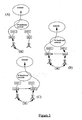
Figures 3A to 3C illustrates a scenario in a UMTS network where SRNS (or SRNC) relocation arises. The network incorporates the Direct Internet Access (DIA) architecture described briefly above and in which the point of connection to the Internet for a particular mobile UE is the SRNC for that user (the SRNC being coupled to the - Internet via an IP backbone network). IP address allocation is handled by respective Access Control Points (
ACP 1 and ACP 2) coupled to the two RNCs. - In
Figure 3A , a RB has been established between the UE and the SRNC and, it is assumed, an IP address allocated to the UE from the pool of IP addresses available to the SRNC. IP datagrams are conveyed over the established RB between the UE and the SRNC. - In
Figure 3B , the situation ofFigure 3A has been modified such that an RB has been established between the SRNC and the UE via a Drift RNC (DRNC). UMTS provides for multiple RBs to exist simultaneously for a given UE in order, for example, to reduce the likelihood of data transmission errors (the same data may be sent simultaneously to and from the UE over two or more RBs). In the situation ofFigure 3B , the SRNC remains in control of the radio resources allocated to the UB and importantly remains the node through which IP packets associated with the UE are routed. The IP address used in the situation ofFigure 3A therefore continues to be used in the situation ofFigure 3B . - In order to optimise the connection path between the core network and the UE (or for other reasons), the SRNC may decide that the DRNC should take over the role of SRNC, as illustrated in
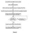
Figure 3C .Figure 4 is a signalling diagram illustrating an IP address changing process which follows this decision. The six signalling steps involve: - 1. The UTRAN (source SRNC) makes the decision to perform the SRNS relocation procedure. This involves making a decision on which RNC the Serving RNC functionality is to be relocated to. The source SRNC sends an SRNS Relocation required message to the
ACP 1. - 2. If
ACP 1 determines from the target RNC Identifier that the SRNS relocation is an inter-ACP SERVING RNC Relocation, thenACP 1 sends a Forward SRNS relocation request toACP 2. - 3. The
ACP 2 is able to initiate an IP address allocation procedure with the UB (e.g. via the current SRNC). Any IP address allocation method can be used such as address allocation by a DHCP server.
In practice,ACP 2 may (immediately) send a Router Advertisement message to the UE so that it may start to acquire a new IP address for the new Gateway (i.e. the RNC Gateway) using normal statefull or stateless IP address allocation methods. During the allocation process, a new IP address, together with an "activation" identity, is sent to the UE. An alternative process involves theACP 2 sending an IP address and an activation identity in one message directly to the UE.
The activation identity is an identity which is associated with the target RNC, and more particularly with the radio link which will be used after SRNS relocation. For example, the identity may be the SRNTI or SRNC identity of the target RNC, or a Core Network (CN) domain identifier - the SRNTI and SRNC together form an identity known as the UTRAN Radio Network Temporary Identity (URNTI).
At the end of the procedure, the UE has a valid IP address for the new SRNC. The UE also knows that the address becomes valid immediately when the activation identity becomes valid. Since the activation identity becomes valid due to some Radio Resources Control operations between the UTRAN and the UE, there is no need for an explicit notification (e.g. on the IP protocol layer). - 4. The SRNS Relocation procedure is finished between source and target nodes (ACPs and RNCs).
- 5. The UE becomes aware of the new activation identity. This phase may be performed during the actual SRNS Relocation procedure or it may be a separate procedure after the SRNS Relocation.
- 6. After the UE has noticed that the activation identity is active, e.g. the Serving RNC Identity is the same as defined in connection with the IP address allocation procedure, the UE may start to use the address. At this stage, the UE must notify the correspondent host(s) so that it (or they) may start to use the new address. The previous SRNS should also be notified of the new IP address. In the case of mobile IP, the home agent will also be notified. Notification may be done using a Binding Update message. The correspondent host(s) may then send data directly to the gateway in the new SRNC.
- This process is further illustrated by the flow diagram of
Figure 5 . - The use of an activation identity which is sent to the UE as an intrinsic part of the relocation procedure or which is incorporated into the existing signalling structure avoids the need for an additional signalling message. However, it will be appreciated that an additional message may be used to activate a new IP address if necessary.
-
Figures 6A and 6B illustrates a hard handover scenario during which the present invention may be employed. The role of serving RNC for the UE is passed directly from a first to a second RNC. Prior to handover, the UE is notified of a new IP address (or means for generating an IP address) such that the new IP address is available immediately following the handover. - It will be appreciated by the person of skill in the art that various modifications may be made to the above described embodiment without departing from the scope of the present invention. For example, whilst the invention has been illustrated with reference to a DIA architecture, it may also be applied in architectures where the SRNS is coupled to the Internet via a core network of the UMTS network. This core network may be a GPRS based network or some other type of packet switched network. Other Internet access architectures are also contemplated.
Claims (11)
- A method of changing the IP address allocated to a mobile UE (3) during a SRNS relocation process in a mobile telecommunications system and in which relocation process, control of the UE (3) is transferred from a currently Serving Radio Network Subsystem (SRNS) (7) to a Target RNS (8), the method comprising:prior to said SRNS relocation taking place, but after it has been decided that a SRNS relocation is required, notifying the UE (3) of a new IP address or means for generating a new IP address; andduring said SRNS relocation process or immediately thereafter replacing the previously used IP address with the new IP address as the in-use IP address,characterised in that, prior to said SRNS relocation taking place, but after it has been decided that a SRNS relocation is required, the UE (3) is notified of an activation identity using which the UE (3) is able to determine when to replace the previously used IP address with the new IP address as the in-use IP address.
- A method according to claim 1, wherein said relocation is carried out as part of or following a hard handover or soft handover process.
- A method according to claim 1 or 2, wherein the mobile telecommunications network has a Direct Internet Access architecture or an architecture in which Internet access is obtained via a core network (1).
- A method according to any one of the preceding claims, wherein the mobile telecommunications system is a Universal Mobile Telecommunications System (UMTS).
- A method according to any one of the preceding claims, wherein IP addresses are allocated by the Serving RNCs (5, 6) or by an Access Control Point (ACP).
- A method according to any preceding claim, wherein said activation identity is a Radio Resource identity such that the new IP address is brought into use when the UE (3) notices that the associated Radio Resource identity is active.
- A method according to claim 6, wherein said Radio Resource identity is a CN domain identity, SRNTI identity, or SRNS identity.
- A method according to any one of the preceding claims, wherein the step of notifying the UE (3) of a new IP address is carried out following the making of a decision to perform SRNS relocation.
- A method according to any one of the preceding claims, wherein the UE (3) is notified of a plurality of new IP addresses and respective activation identities, prior to one or more SRNS relocation processes.
- A mobile telecommunications system comprising means for notifying a mobile UE (3) of a new IP address or means for generating a new IP address prior to carrying out a SRNS relocation process whereby control of the UE (3) is transferred from a currently Serving Radio Network Subsystem (SRNS) (7) to a Target RNS (8), the UE (3) being arranged to replace the previously used IP address with the new IP address as the in-use IP address during said SRNS relocation process or immediately thereafter,
characterized by means for notifying the UE (3), prior to said SRNS relocation taking place, but after it has been decided that a SRNS relocation is required, of an activation identity using which the UE (3) is able to determine when to replace the previously used IP address with the new IP address as the in-use IP address. - A mobile User Equipment (UE) (3) comprising:receiving means for receiving from a mobile telecommunications network a new IP address or means for generating a new IP address while the UE (3) is using a previously allocated IP address;first processing means for recognising when said previously allocated IP address should be replaced by said new IP address, following an SRNS relocation; andsecond processing means for replacing said previously allocated IP address with said new IP address following recognition for subsequent IP access,characterized in that the UE (3) is arranged to receive, prior to said SRNS relocation taking place, but after a decision has been taken that a SRNS relocation is required, an activation identity using which the UE (3) is able to determine when to replace the previously used IP address with the new IP address as the in-use IP address.
Applications Claiming Priority (3)
| Application Number | Priority Date | Filing Date | Title |
|---|---|---|---|
| GBGB0012623.5A GB0012623D0 (en) | 2000-05-25 | 2000-05-25 | Ip address allocation in a mobile telecommunications network |
| GB0012623 | 2000-05-25 | ||
| PCT/EP2001/005811 WO2001091420A2 (en) | 2000-05-25 | 2001-05-21 | Ip address allocation in a mobile telecommunications network |
Publications (2)
| Publication Number | Publication Date |
|---|---|
| EP1290848A2 EP1290848A2 (en) | 2003-03-12 |
| EP1290848B1 true EP1290848B1 (en) | 2009-08-26 |
Family
ID=9892281
Family Applications (1)
| Application Number | Title | Priority Date | Filing Date |
|---|---|---|---|
| EP01929651A Expired - Lifetime EP1290848B1 (en) | 2000-05-25 | 2001-05-21 | Ip address allocation in a mobile telecommunications network |
Country Status (7)
| Country | Link |
|---|---|
| EP (1) | EP1290848B1 (en) |
| AT (1) | ATE441277T1 (en) |
| AU (1) | AU2001256360A1 (en) |
| DE (1) | DE60139687D1 (en) |
| ES (1) | ES2330921T3 (en) |
| GB (1) | GB0012623D0 (en) |
| WO (1) | WO2001091420A2 (en) |
Families Citing this family (5)
| Publication number | Priority date | Publication date | Assignee | Title |
|---|---|---|---|---|
| US7047036B2 (en) | 2002-07-02 | 2006-05-16 | Interdigital Technology Corporation | Method and apparatus for handoff between a wireless local area network (WLAN) and a universal mobile telecommunication system (UMTS) |
| TWI471028B (en) | 2003-11-13 | 2015-01-21 | Interdigital Tech Corp | Method and wireless transmit/receive unit for facilitating handover |
| MXPA06010238A (en) | 2004-03-12 | 2007-01-10 | Interdigital Tech Corp | Method and system for switching a radio access technology between wireless communicaiton systems with a multi-mode wireless transmit/receive unit. |
| DE102004027811B4 (en) | 2004-06-08 | 2012-08-30 | Infineon Technologies Ag | A communication device, a subscriber device, a control device, a method for controlling a communication system, a method for controlling a subscriber device and a method for controlling a control device |
| JP5357913B2 (en) * | 2011-03-24 | 2013-12-04 | 株式会社エヌ・ティ・ティ・ドコモ | Mobile communication method |
Family Cites Families (6)
| Publication number | Priority date | Publication date | Assignee | Title |
|---|---|---|---|---|
| DE69325844T2 (en) * | 1992-04-17 | 2000-08-31 | Ericsson Telefon Ab L M | Mobile-assisted handoff with code division multiple access |
| SE515256C2 (en) * | 1996-02-12 | 2001-07-02 | Telia Ab | LAN network and method of providing uninterrupted transmission between two switches in a LAN |
| JP3529621B2 (en) * | 1997-05-12 | 2004-05-24 | 株式会社東芝 | Router device, datagram transfer method, and communication system |
| US6147986A (en) * | 1998-03-06 | 2000-11-14 | Lucent Technologies Inc. | Address updating of wireless mobile terminal hosts affiliated with a wired network |
| FI105969B (en) * | 1998-08-10 | 2000-10-31 | Nokia Networks Oy | Quality of service management in a mobile communication system |
| EP0987860A3 (en) * | 1998-09-16 | 2004-01-14 | Mitsubishi Materials Corporation | Radio server system |
-
2000
- 2000-05-25 GB GBGB0012623.5A patent/GB0012623D0/en not_active Ceased
-
2001
- 2001-05-21 DE DE60139687T patent/DE60139687D1/en not_active Expired - Lifetime
- 2001-05-21 EP EP01929651A patent/EP1290848B1/en not_active Expired - Lifetime
- 2001-05-21 AT AT01929651T patent/ATE441277T1/en not_active IP Right Cessation
- 2001-05-21 AU AU2001256360A patent/AU2001256360A1/en not_active Abandoned
- 2001-05-21 WO PCT/EP2001/005811 patent/WO2001091420A2/en active Application Filing
- 2001-05-21 ES ES01929651T patent/ES2330921T3/en not_active Expired - Lifetime
Also Published As
| Publication number | Publication date |
|---|---|
| WO2001091420A3 (en) | 2002-03-14 |
| WO2001091420A2 (en) | 2001-11-29 |
| ATE441277T1 (en) | 2009-09-15 |
| ES2330921T3 (en) | 2009-12-17 |
| EP1290848A2 (en) | 2003-03-12 |
| GB0012623D0 (en) | 2000-07-12 |
| DE60139687D1 (en) | 2009-10-08 |
| AU2001256360A1 (en) | 2001-12-03 |
Similar Documents
| Publication | Publication Date | Title |
|---|---|---|
| EP1166523B1 (en) | Ip address allocation for mobile terminals | |
| US8824430B2 (en) | Wireless mobility gateway | |
| US8249025B2 (en) | Methods and systems for providing improved handoffs in a wireless communication system | |
| EP1360864B1 (en) | Paging method and system for a radio access network | |
| EP1658749B1 (en) | Identifying network resources for packet-switched services | |
| JP5740672B2 (en) | Telecommunication system and telecommunication method | |
| KR100403731B1 (en) | Core network separation structure an signal processing method thereof in mobile communication system | |
| US20050130659A1 (en) | Method for optimizing handover between communication networks | |
| US20040029587A1 (en) | Method for supporting a handover between radio access networks | |
| US20040127237A1 (en) | Connection establishment for PDP contexts | |
| WO2005008964A1 (en) | Seamless hand-off of mobile node to a wireless local area network (wlan) | |
| WO2003061219A3 (en) | System and method for improved session management in a data cellular network | |
| US8045522B2 (en) | Method and system for performing handoff in wireless networks | |
| KR100375825B1 (en) | Hard Handoff Method for Packet Mobile Network | |
| EP1290848B1 (en) | Ip address allocation in a mobile telecommunications network | |
| WO2009013099A1 (en) | A method for routing traffic across an ip-based transport network in a mobile network | |
| US20020039358A1 (en) | Method for separating and processing signal and bearer in all IP radio access network | |
| KR100617780B1 (en) | Method for updating routing area of mobile node in wireless internet and mobile communication network | |
| KR100636328B1 (en) | Apparatus and method of handovver on cellular system using the heterogeneous wireless network | |
| WO2007110480A1 (en) | Improved information transfer | |
| KR20100118407A (en) | Apparatus system and method for providing packet service using mobile ip |
Legal Events
| Date | Code | Title | Description |
|---|---|---|---|
| PUAI | Public reference made under article 153(3) epc to a published international application that has entered the european phase |
Free format text: ORIGINAL CODE: 0009012 |
|
| 17P | Request for examination filed |
Effective date: 20021220 |
|
| AK | Designated contracting states |
Kind code of ref document: A2 Designated state(s): AT BE CH CY DE DK ES FI FR GB GR IE IT LI LU MC NL PT SE TR |
|
| AX | Request for extension of the european patent |
Extension state: AL LT LV MK RO SI |
|
| 17Q | First examination report despatched |
Effective date: 20030827 |
|
| RAP1 | Party data changed (applicant data changed or rights of an application transferred) |
Owner name: TELEFONAKTIEBOLAGET LM ERICSSON (PUBL) |
|
| 17Q | First examination report despatched |
Effective date: 20030827 |
|
| GRAP | Despatch of communication of intention to grant a patent |
Free format text: ORIGINAL CODE: EPIDOSNIGR1 |
|
| GRAS | Grant fee paid |
Free format text: ORIGINAL CODE: EPIDOSNIGR3 |
|
| GRAA | (expected) grant |
Free format text: ORIGINAL CODE: 0009210 |
|
| AK | Designated contracting states |
Kind code of ref document: B1 Designated state(s): AT BE CH CY DE DK ES FI FR GB GR IE IT LI LU MC NL PT SE TR |
|
| REG | Reference to a national code |
Ref country code: GB Ref legal event code: FG4D |
|
| REG | Reference to a national code |
Ref country code: CH Ref legal event code: EP |
|
| REG | Reference to a national code |
Ref country code: IE Ref legal event code: FG4D |
|
| REF | Corresponds to: |
Ref document number: 60139687 Country of ref document: DE Date of ref document: 20091008 Kind code of ref document: P |
|
| REG | Reference to a national code |
Ref country code: ES Ref legal event code: FG2A Ref document number: 2330921 Country of ref document: ES Kind code of ref document: T3 |
|
| PG25 | Lapsed in a contracting state [announced via postgrant information from national office to epo] |
Ref country code: FI Free format text: LAPSE BECAUSE OF FAILURE TO SUBMIT A TRANSLATION OF THE DESCRIPTION OR TO PAY THE FEE WITHIN THE PRESCRIBED TIME-LIMIT Effective date: 20090826 Ref country code: SE Free format text: LAPSE BECAUSE OF FAILURE TO SUBMIT A TRANSLATION OF THE DESCRIPTION OR TO PAY THE FEE WITHIN THE PRESCRIBED TIME-LIMIT Effective date: 20090826 Ref country code: AT Free format text: LAPSE BECAUSE OF FAILURE TO SUBMIT A TRANSLATION OF THE DESCRIPTION OR TO PAY THE FEE WITHIN THE PRESCRIBED TIME-LIMIT Effective date: 20090826 |
|
| NLV1 | Nl: lapsed or annulled due to failure to fulfill the requirements of art. 29p and 29m of the patents act | ||
| PG25 | Lapsed in a contracting state [announced via postgrant information from national office to epo] |
Ref country code: NL Free format text: LAPSE BECAUSE OF FAILURE TO SUBMIT A TRANSLATION OF THE DESCRIPTION OR TO PAY THE FEE WITHIN THE PRESCRIBED TIME-LIMIT Effective date: 20090826 |
|
| PG25 | Lapsed in a contracting state [announced via postgrant information from national office to epo] |
Ref country code: CY Free format text: LAPSE BECAUSE OF FAILURE TO SUBMIT A TRANSLATION OF THE DESCRIPTION OR TO PAY THE FEE WITHIN THE PRESCRIBED TIME-LIMIT Effective date: 20090826 Ref country code: PT Free format text: LAPSE BECAUSE OF FAILURE TO SUBMIT A TRANSLATION OF THE DESCRIPTION OR TO PAY THE FEE WITHIN THE PRESCRIBED TIME-LIMIT Effective date: 20091228 |
|
| PG25 | Lapsed in a contracting state [announced via postgrant information from national office to epo] |
Ref country code: DK Free format text: LAPSE BECAUSE OF FAILURE TO SUBMIT A TRANSLATION OF THE DESCRIPTION OR TO PAY THE FEE WITHIN THE PRESCRIBED TIME-LIMIT Effective date: 20090826 |
|
| PG25 | Lapsed in a contracting state [announced via postgrant information from national office to epo] |
Ref country code: BE Free format text: LAPSE BECAUSE OF FAILURE TO SUBMIT A TRANSLATION OF THE DESCRIPTION OR TO PAY THE FEE WITHIN THE PRESCRIBED TIME-LIMIT Effective date: 20090826 |
|
| PLBE | No opposition filed within time limit |
Free format text: ORIGINAL CODE: 0009261 |
|
| STAA | Information on the status of an ep patent application or granted ep patent |
Free format text: STATUS: NO OPPOSITION FILED WITHIN TIME LIMIT |
|
| 26N | No opposition filed |
Effective date: 20100527 |
|
| PG25 | Lapsed in a contracting state [announced via postgrant information from national office to epo] |
Ref country code: GR Free format text: LAPSE BECAUSE OF FAILURE TO SUBMIT A TRANSLATION OF THE DESCRIPTION OR TO PAY THE FEE WITHIN THE PRESCRIBED TIME-LIMIT Effective date: 20091127 |
|
| PG25 | Lapsed in a contracting state [announced via postgrant information from national office to epo] |
Ref country code: MC Free format text: LAPSE BECAUSE OF NON-PAYMENT OF DUE FEES Effective date: 20100531 |
|
| REG | Reference to a national code |
Ref country code: CH Ref legal event code: PL |
|
| PG25 | Lapsed in a contracting state [announced via postgrant information from national office to epo] |
Ref country code: LI Free format text: LAPSE BECAUSE OF NON-PAYMENT OF DUE FEES Effective date: 20100531 Ref country code: CH Free format text: LAPSE BECAUSE OF NON-PAYMENT OF DUE FEES Effective date: 20100531 |
|
| PG25 | Lapsed in a contracting state [announced via postgrant information from national office to epo] |
Ref country code: IE Free format text: LAPSE BECAUSE OF NON-PAYMENT OF DUE FEES Effective date: 20100521 |
|
| PG25 | Lapsed in a contracting state [announced via postgrant information from national office to epo] |
Ref country code: LU Free format text: LAPSE BECAUSE OF NON-PAYMENT OF DUE FEES Effective date: 20100521 |
|
| PG25 | Lapsed in a contracting state [announced via postgrant information from national office to epo] |
Ref country code: TR Free format text: LAPSE BECAUSE OF FAILURE TO SUBMIT A TRANSLATION OF THE DESCRIPTION OR TO PAY THE FEE WITHIN THE PRESCRIBED TIME-LIMIT Effective date: 20090826 |
|
| REG | Reference to a national code |
Ref country code: FR Ref legal event code: PLFP Year of fee payment: 15 |
|
| PGFP | Annual fee paid to national office [announced via postgrant information from national office to epo] |
Ref country code: GB Payment date: 20150527 Year of fee payment: 15 Ref country code: ES Payment date: 20150526 Year of fee payment: 15 Ref country code: DE Payment date: 20150528 Year of fee payment: 15 |
|
| PGFP | Annual fee paid to national office [announced via postgrant information from national office to epo] |
Ref country code: IT Payment date: 20150527 Year of fee payment: 15 Ref country code: FR Payment date: 20150519 Year of fee payment: 15 |
|
| REG | Reference to a national code |
Ref country code: DE Ref legal event code: R119 Ref document number: 60139687 Country of ref document: DE |
|
| GBPC | Gb: european patent ceased through non-payment of renewal fee |
Effective date: 20160521 |
|
| PG25 | Lapsed in a contracting state [announced via postgrant information from national office to epo] |
Ref country code: IT Free format text: LAPSE BECAUSE OF NON-PAYMENT OF DUE FEES Effective date: 20160521 |
|
| REG | Reference to a national code |
Ref country code: FR Ref legal event code: ST Effective date: 20170131 |
|
| PG25 | Lapsed in a contracting state [announced via postgrant information from national office to epo] |
Ref country code: DE Free format text: LAPSE BECAUSE OF NON-PAYMENT OF DUE FEES Effective date: 20161201 Ref country code: FR Free format text: LAPSE BECAUSE OF NON-PAYMENT OF DUE FEES Effective date: 20160531 |
|
| PG25 | Lapsed in a contracting state [announced via postgrant information from national office to epo] |
Ref country code: GB Free format text: LAPSE BECAUSE OF NON-PAYMENT OF DUE FEES Effective date: 20160521 |
|
| PG25 | Lapsed in a contracting state [announced via postgrant information from national office to epo] |
Ref country code: ES Free format text: LAPSE BECAUSE OF NON-PAYMENT OF DUE FEES Effective date: 20160522 |
|
| REG | Reference to a national code |
Ref country code: ES Ref legal event code: FD2A Effective date: 20181203 |