EP1290657B1 - Gerät zum erfassen von überhitzung in einem linear-wärme-sensorkabel - Google Patents
Gerät zum erfassen von überhitzung in einem linear-wärme-sensorkabel Download PDFInfo
- Publication number
- EP1290657B1 EP1290657B1 EP01936809A EP01936809A EP1290657B1 EP 1290657 B1 EP1290657 B1 EP 1290657B1 EP 01936809 A EP01936809 A EP 01936809A EP 01936809 A EP01936809 A EP 01936809A EP 1290657 B1 EP1290657 B1 EP 1290657B1
- Authority
- EP
- European Patent Office
- Prior art keywords
- cable
- detecting device
- fire
- fact
- terminals
- Prior art date
- Legal status (The legal status is an assumption and is not a legal conclusion. Google has not performed a legal analysis and makes no representation as to the accuracy of the status listed.)
- Expired - Lifetime
Links
Images


Classifications
-
- G—PHYSICS
- G08—SIGNALLING
- G08B—SIGNALLING SYSTEMS, e.g. PERSONAL CALLING SYSTEMS; ORDER TELEGRAPHS; ALARM SYSTEMS
- G08B25/00—Alarm systems in which the location of the alarm condition is signalled to a central station, e.g. fire or police telegraphic systems
- G08B25/01—Alarm systems in which the location of the alarm condition is signalled to a central station, e.g. fire or police telegraphic systems characterised by the transmission medium
- G08B25/04—Alarm systems in which the location of the alarm condition is signalled to a central station, e.g. fire or police telegraphic systems characterised by the transmission medium using a single signalling line, e.g. in a closed loop
-
- G—PHYSICS
- G08—SIGNALLING
- G08B—SIGNALLING SYSTEMS, e.g. PERSONAL CALLING SYSTEMS; ORDER TELEGRAPHS; ALARM SYSTEMS
- G08B17/00—Fire alarms; Alarms responsive to explosion
- G08B17/06—Electric actuation of the alarm, e.g. using a thermally-operated switch
Definitions
- This invention concerns a device for the detection of the alarm position of an alarm generated in a special cable defined as "Linear Heat Detector” (L.H.D.).
- the L.H.D.'s are cables used for fire alarm signalisation when exposed to temperatures in excess of the selected minimum alarm level produced in the environment or in a plant, as for an example, but not exclusively, in highway-railways-underground tunnels, belt conveyors, electrical cabinets and power lines cable trays, transformers, flammable storage tanks, cooling towers, in warehouses and in any case in all those installations where, caused by attrition, by chemical reactions or by short-circuit there could be the conditions for the development of a fire and in which it's useful to identify as soon as possible the exact location of the danger, above all in case of great plants or of long length runs
- An L.H.D. is an electrical twisted pair of stainless steel conductors cable provided with a special thermoplastic sensitive insulation which melts at selected temperature levels. When exposed to temperature in excess of the selected minimum alarm level the specific sensitive insulation melts allowing the conductors to short-circuit. It's, therefore, an on-off digital device.
- the alarm condition is monitored through a fire control panel which monitors the status ( fire or fault) checking the current output from the control panel.
- the main problem in plants with linear heat detectors installed is that the fire control panels management system can identify the status of alarm of the "zone" in which the cable is installed, but can't identify precisely the location in that zone, i.e. the distance from a conventional reference distance. This problem is particularly serious when, as in tunnels or in cable trays, the cable lengths are relevant.
- EP-A-0 011 461 discloses a device for detecting in a long area to be attended a burning fire by using known L inear H eat D etector (L.H.D. cables). Said area which may have a length up to 4 Km or more are subdivided in a plurality of single discrete zones through which a L.H.D. cable runs. Each zone is provided with a resistor being series connected to the own traditional electrical conductor of said L.H.D. cable. In case of a burning fire the related zone is determined by the value of the measured voltage drop across the cable/resistor arrangement with the result being correlated to the zone and fed to a monitoring device.
- L.H.D. cables L inear H eat D etector
- US-A-3800216 discloses a device which makes use of traditional electrical conductors only and not of L.H.D. or heat sensitive cables which latter being specifically designed for fire detecting purposes.
- the suggested device is designed for detecting the location of cable faults or short circuits in common electrical conductors and not for detecting the location of fire alarms by means of heat sensitive cables.
- the object of the present invention is to provide a device which is able to identify the distance of alarm in any digital cable, no matter which is the manufacturer, or in other terms no matter which are the electrical parameters of the digital cable electrical features.
- the device according to this invention is capable to display the location of alarm in meters or in feet or in any other measuring unit, and the display can be local in alphanumeric display or remote on a PC screen with a digital map or a drawing of the site, indicating the exact location of the fire.
- the achieved precision is superior in the range of 1% to 3% max for length of cable over 4.000mt, with environmental temperature variation ranging from +/-20°C.
- the device is realized in portable or fixed version , the portable one for maintenance purposes , the fixed one to be installed in electrical cabinet or control rooms.
- the electronic unit features a microprocessor for measuring the voltage drop on L.H.D, comparing it with physical parameters stored in a memory as reference and in displaying locally or remotely via PC .
- control unit is capable of discriminating short-circuit on L.H.D from a short-circuit on electrical junction cable or for its opening status ( as for example for interruption of its continuity )
- the electronic board is powered via a 24VDC charger through a connector.
- the power block generates a 15VDC - 10V-12,5V supply reference voltages .
- Terminals are provided for L.H.D input, which is connected to a reference relay and in stand-by terminates on proper terminals;
- This version of the circuit capable of detecting the voltage drop on a L. H.D. cable is powered through 9Vdc battery and is provided with :
- the device is constituted by an electronic board capable of measuring the voltage drop on L.H.D. cable digital type of any manufacturer and to compare it to reference parameters and displaying it with a precision in the range 1-3% max, in function of the environment temperature of the L.H.D. in alarm, as described in the following examples.
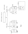
- Example 1 (electronic board, fixed version)
- the circuit is powered at 24 V dc through a proper connector (variable with the control unit).
- the circuit generates a 15 V dc voltage and 10 V dc-12,5 V dc reference voltages.
- the input line from the L.H.D. in the field passes through a relay and in stand-by terminates on terminals.
- two steady current generators power a reference resistor and the line to be measured.
- the relay When an alarm is generated, via terminal, or via manual pressure, the relay changes over an amplifier circuit.
- a trimmer zeroes the junction electrical cables resistance up to the beginning or the end of the L.H.D.
- a resistor regulates the amplification of the circuit.
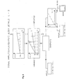
- Example 2 (electronic board for portable version control units)
- the electronic board is powered through a 9 V battery. Pressing the pushbutton, the voltmeter module is capable to produce a reference voltage proportional to the resistance calibration value, to set in function of the L.H.D. type, which has to be connected on provided terminals; two diodes are provided for a protection function.
- the device according invention provides means to reset the system, to store the data, to acknowledge the alarm until problem resolution, and to sequentially investigate many zones of L.H.D.
- the control unit is capable to control external devices for fire extinguishing.
- the device operation is based on the current variation between a reference value and the alarm value. This variation in turn depends from the distance of the alarm point (i.e. of the L.H.D. resistance).
- the circuitry sends continuously a signal into the cable and if the cable is whole the signal turns back unchanged. If on the contrary there is a short circuit the circuit measures the voltage drop and translates it in a reference value which is properly displayed.
Landscapes
- Business, Economics & Management (AREA)
- Emergency Management (AREA)
- Physics & Mathematics (AREA)
- General Physics & Mathematics (AREA)
- Alarm Systems (AREA)
- Fire Alarms (AREA)
- General Induction Heating (AREA)
- Fire-Detection Mechanisms (AREA)
- Cable Accessories (AREA)
- Locating Faults (AREA)
Claims (10)
- Erfassungsgerät zur Erfassung der Stelle wo ein Feuer in der Nähe einer langen Erfassungsstrecke von z. B. 4.000 m und mehr brennt, die aus einem ein bekanntes Linear-Wärme-Sensorkabel (L.H.D.) bildenden Mittel besteht, das mit einem eigenen Endwiderstand versehen und durch einen eigenen gemeinsamen Rück-Kabel mit einer entfernten Kontrollstation verbunden ist, die das genannte Erfassungsgerät aufnimmt, das mit einer Spannungsquelle zur Erzeugung eines Speisestroms als ein in das das genannte L.H.D.-Kabel bildende Mittel gesandtes Signal versehen ist, wobei die Rückkehr von diesem genannten Signal zum genannten Prüfgerät die Integrität des genannten das L.H.D.-Kabel bildenden Mittels gewährleistet, wogegen ein von einem Kurzschluss/Feuer verursachten Spannungsabfall die Angabe auf einem Display einer Länge des L.H.D.-Kabels bewirkt, wo der Kurzschluss/das Feuer gerade erfolgt, wobei das Erfassungsgerät ferner:- eine vorbereitete elektronische Platte, die in der genannten eine einzige lange Erfassungsstrecke bildenden Erfassungsstrecke arbeitet, die aus diesem bekannten das L.H.D-Kabel bildenden Mittel besteht,- Mittel, die fähig sind, den Spannungsabfall zu messen, der zu einem Kurzschluss/Feuer in der genannten Strecke des L.H.D.-Kabels, ohne Rücksicht auf deren elektrischen Parameter, zurückzuführen ist, und- Vergleichsmittel, die fähig sind, den genannten Spannungsabfall mit voreingestellten gespeicherten Bezugsparametern zu vergleichen und diese genannten Spannungsabfalländerungen in eine auf einem Display angegebene Angabe umzuwandeln, die die zwischen dem Anfangsende der genannte Strecke des L.H.D.-Kabels und der Stelle (dem Punkt) in dieser Strecke bestehende Entfernung angibt, wo der Kurzschluss/das Feuer erfolgt,enthält.
- Erfassungsgerät nach Anspruch 1, in einer Ausführung als ein sich in einer in einer entfernten Überwachungsstation befindenden Steuertafel aufzunehmenden Gerät, dadurch gekennzeichnet, dass das Erfassungsgerät:- eine von einer Spannungsquelle von 24 V gespeiste elektrische Schaltung, die eine Speisespannung von 15 Volt sowie Bezugspannungen von 10V und 12,5V liefert,- eine Eingangslinie vom L.H.D.-Kabel, die durch ein Bezugsrelais hindurch geführt und in seiner Bereitschaftstellung mit den Klemmen eines bipolaren Verbinders verbunden ist,- eine gedrückte Schaltungen aufweisende elektronisch arbeitende Platte, die zwei Konstantstromgeneratoren enthält, die einen Bezugswiderstand und die das genannte L.H.D.-Kabel enthaltende zu messende Linie speist,- einen Trimmer zum auf Null stellen der gemeinsamen Kabel, die mit dem genannten L.H.D.-Kabel verbunden sind,- einen Einstelltrimmer zur Steuerung der Schaltungsverstärkung,- einen Analogausgang von 0 bis 10V zwischen dem ersten Klemmenpaar der genannten elektronisch arbeitenden Platte und einen Analogausgang von 0 bis 20 mA zwischen dem zweiten Klemmenpaar der genannten elektronisch arbeitenden Platte, wobei die genannten Klemmenpaare getrennt zu verwenden sind,enthält.
- Erfassungsgerät nach Anspruch 1, in der Ausführung als ein tragbares Gerät, dadurch gekennzeichnet, dass das Erfassungsgerät:- eine Batterie mit einer Leistung von 9V,- ein voltmetrisches Modul in der genannten elektronisch arbeitenden Platte, das fähig ist, eine Referenzspannung zu liefern, die gleich wie ein Wert ist, der vorher nach den Parametern des genannten zu überwachenden L.H.D.-Kabels bestimmt wurde,- zwei den zu überwachenden L.H.D.-Kabel aufnehmende Klemmen,- zwei Dioden zum Schützen des Erfassungsgeräteinganges,enthält.
- Erfassungsgerät nach einem oder mehr der vorhergehenden Ansprüche, dadurch gekennzeichnet, dass der auf dem Display angegebene Abstand in Metern, Füße, u.s.w. der Abstand ist, der zwischen der Kurzschluss/Feuer-Stelle im genannten L.H.D.-Kabel und dem Anfang oder dem Ende des letzteren besteht.
- Erfassungsgerät nach einem oder mehr der vorhergehenden Ansprüche, dadurch gekennzeichnet, dass die Rückstellung auf den Anfangszustand des Erfassungsgerätes durch Relais oder andere bekannte Mittel durchgeführt ist.
- Erfassungsgerät nach einem oder mehr der vorhergehenden Ansprüche, dadurch gekennzeichnet, dass ein Mittel zum Speichern von Alarmdaten und entstandenen Ereignissen enthalten sind.
- Erfassungsgerät nach einem oder mehr der vorhergehenden Ansprüche, dadurch gekennzeichnet, dass das Erfassungsgerät für eine gleichzeitige oder sequentielle Überwachung von einer Mehrzahl von verschiedenen und beliebig installierten L.H.D.-Kabeln voreingestellt ist.
- Erfassungsgerät nach Anspruch 3 bis 7, dadurch gekennzeichnet, dass das Erfassungsgerät in einem schachtelartigen Behälter aufgenommen ist, der einen Display, ein Klemmenpaar zur Aufnahme der beiden Enden eines L.H.D.-Kabels, einen Hauptschalter, die genannte elektronisch arbeitende und gedrückte Schaltungen aufweisende Platte und Speisebatterien enthält.
- Erfassungsgerät nach einem oder mehr der vorhergehenden Ansprüche, dadurch gekennzeichnet, dass das Erfassungsgerät für eine manuelle und/oder automatische Steuerung von Löschungssystemen für ortsbestimmte Feuer voreingestellt ist.
- Erfassungsgerät nach einem oder mehr der vorhergehenden Ansprüche, dadurch gekennzeichnet, dass das Erfassungsgerät ferner ein eingegliedertes Mittel zur Unterscheidung zwischen einem im L.H.D.-Kabel stattfindenden Kurzshluss/Feuer und einem in den gemeinsamen Schaltungskabeln entstandenen Defekt, welche Schaltungskabeln mit dem genannten L.H.D.-Kabel entweder stromauf oder stromab mit dem letzteren verbunden sind, wobei das genannte Mittel durch die Kupplung der genannten elektronischen mit gedrückten Schaltungen versehenen Platte mit einer mit gedrückten Schaltungen versehenen bekannter "DSM" genannter Platte der Anmelderin für die Betriebsführung von Feuererfassungsgeräten gebildet ist.
Applications Claiming Priority (3)
| Application Number | Priority Date | Filing Date | Title |
|---|---|---|---|
| ITMI200115 | 2000-05-25 | ||
| IT2000MI001153A IT1317566B1 (it) | 2000-05-25 | 2000-05-25 | Apparecchiatura atta a rilevare la posizione di un allarme termico incavi termosensibili, utilizzabile sia per il montaggio in un quadro |
| PCT/IT2001/000251 WO2001091076A1 (en) | 2000-05-25 | 2001-05-18 | Device to detect heating levels in excess in l.h.d cables |
Publications (2)
| Publication Number | Publication Date |
|---|---|
| EP1290657A1 EP1290657A1 (de) | 2003-03-12 |
| EP1290657B1 true EP1290657B1 (de) | 2007-05-02 |
Family
ID=11445113
Family Applications (1)
| Application Number | Title | Priority Date | Filing Date |
|---|---|---|---|
| EP01936809A Expired - Lifetime EP1290657B1 (de) | 2000-05-25 | 2001-05-18 | Gerät zum erfassen von überhitzung in einem linear-wärme-sensorkabel |
Country Status (6)
| Country | Link |
|---|---|
| EP (1) | EP1290657B1 (de) |
| AT (1) | ATE361514T1 (de) |
| AU (1) | AU2001262667A1 (de) |
| DE (1) | DE60128220D1 (de) |
| IT (1) | IT1317566B1 (de) |
| WO (1) | WO2001091076A1 (de) |
Families Citing this family (1)
| Publication number | Priority date | Publication date | Assignee | Title |
|---|---|---|---|---|
| CN100426332C (zh) * | 2006-12-20 | 2008-10-15 | 首安工业消防有限公司 | 一种用于不可恢复式线型感温探测器的短路报警方法 |
Family Cites Families (5)
| Publication number | Priority date | Publication date | Assignee | Title |
|---|---|---|---|---|
| US3257530A (en) * | 1963-11-01 | 1966-06-21 | John S Davies | Heat-sensing cable |
| US3800216A (en) * | 1971-08-11 | 1974-03-26 | Dynatel Corp | Cable fault locator apparatus and method with reference voltage comparison |
| EP0011461A1 (de) * | 1978-11-10 | 1980-05-28 | BICC Limited | Ein verbessertes Feuerdetektionssystem |
| DE3806058A1 (de) * | 1988-02-26 | 1989-09-07 | Philips Patentverwaltung | Messvorrichtung zur widerstandsmessung |
| US5412374A (en) * | 1994-05-24 | 1995-05-02 | Clinton; Henry H. | Method and apparatus for detecting and indicating the location of a high temperature zone along the length of a fire detecting cable |
-
2000
- 2000-05-25 IT IT2000MI001153A patent/IT1317566B1/it active
-
2001
- 2001-05-18 AU AU2001262667A patent/AU2001262667A1/en not_active Abandoned
- 2001-05-18 DE DE60128220T patent/DE60128220D1/de not_active Expired - Lifetime
- 2001-05-18 WO PCT/IT2001/000251 patent/WO2001091076A1/en not_active Ceased
- 2001-05-18 AT AT01936809T patent/ATE361514T1/de not_active IP Right Cessation
- 2001-05-18 EP EP01936809A patent/EP1290657B1/de not_active Expired - Lifetime
Also Published As
| Publication number | Publication date |
|---|---|
| ATE361514T1 (de) | 2007-05-15 |
| ITMI20001153A0 (it) | 2000-05-25 |
| IT1317566B1 (it) | 2003-07-09 |
| ITMI20001153A1 (it) | 2001-11-25 |
| EP1290657A1 (de) | 2003-03-12 |
| WO2001091076A1 (en) | 2001-11-29 |
| DE60128220D1 (de) | 2007-06-14 |
| AU2001262667A1 (en) | 2001-12-03 |
Similar Documents
| Publication | Publication Date | Title |
|---|---|---|
| CA2654411C (en) | User interface for monitoring a plurality of faulted circuit indicators | |
| GB2552447B (en) | Fault monitoring systems and methods for detecting connectivity faults | |
| US9251682B2 (en) | System and method for fire preventing in electrical installations | |
| KR102308420B1 (ko) | 수배전반용 온도센서를 포함한 모니터링시스템(고압반, 저압반, 전동기 제어반, 분전반) | |
| US7692538B2 (en) | User interface for monitoring a plurality of faulted circuit indicators | |
| US10761129B2 (en) | Electrical power supply panel with increased safety through monitoring and control | |
| KR102308421B1 (ko) | 모니터링장치가 구비된 수배전반(고압반, 저압반, 전동기 제어반, 분전반) | |
| US6611208B1 (en) | Integrated field monitoring and communications system | |
| US6288637B1 (en) | Fire protection system | |
| US4329643A (en) | Portable circuit testing system | |
| EP1290657B1 (de) | Gerät zum erfassen von überhitzung in einem linear-wärme-sensorkabel | |
| US20070157705A1 (en) | Leak detection system with addressable sensors | |
| CA1235458A (en) | Apparatus for monitoring circuit integrity | |
| EP1535383B1 (de) | Temperatur berwachungssystem für elektrische geräte | |
| EP0011461A1 (de) | Ein verbessertes Feuerdetektionssystem | |
| KR100191643B1 (ko) | 통신구 집중 관리 방법 및 그 장치 | |
| CN213397374U (zh) | 一种在线测量端子排温度的测温装置 | |
| GB2189613A (en) | Testing electrical circuitry or components | |
| GB2043974A (en) | Fire detection system | |
| CN219551729U (zh) | 温度显示表头通电检验装置 | |
| EP0160440A1 (de) | Vorrichtung zur Feststellung und zum Erhalt von Information über Änderungen von Variablen | |
| KR100953684B1 (ko) | 전기적 이상상태 감지기능을 구비한 터널램프제어용 분·배전반 | |
| KR200388511Y1 (ko) | 가스 시설의 압력을 관리하는 장치 | |
| Baen | The value of controls and monitoring for electrical heat tracing | |
| CN112254823A (zh) | 一种实时监测端子排温度的测温装置 |
Legal Events
| Date | Code | Title | Description |
|---|---|---|---|
| PUAI | Public reference made under article 153(3) epc to a published international application that has entered the european phase |
Free format text: ORIGINAL CODE: 0009012 |
|
| 17P | Request for examination filed |
Effective date: 20021222 |
|
| AK | Designated contracting states |
Kind code of ref document: A1 Designated state(s): AT BE CH CY DE DK ES FI FR GB GR IE IT LI LU MC NL PT SE TR |
|
| AX | Request for extension of the european patent |
Extension state: AL LT LV MK RO SI |
|
| 17Q | First examination report despatched |
Effective date: 20030507 |
|
| GRAP | Despatch of communication of intention to grant a patent |
Free format text: ORIGINAL CODE: EPIDOSNIGR1 |
|
| GRAS | Grant fee paid |
Free format text: ORIGINAL CODE: EPIDOSNIGR3 |
|
| GRAA | (expected) grant |
Free format text: ORIGINAL CODE: 0009210 |
|
| AK | Designated contracting states |
Kind code of ref document: B1 Designated state(s): AT BE CH CY DE DK ES FI FR GB GR IE IT LI LU MC NL PT SE TR |
|
| PG25 | Lapsed in a contracting state [announced via postgrant information from national office to epo] |
Ref country code: FI Free format text: LAPSE BECAUSE OF FAILURE TO SUBMIT A TRANSLATION OF THE DESCRIPTION OR TO PAY THE FEE WITHIN THE PRESCRIBED TIME-LIMIT Effective date: 20070502 |
|
| REG | Reference to a national code |
Ref country code: GB Ref legal event code: FG4D |
|
| REG | Reference to a national code |
Ref country code: CH Ref legal event code: EP |
|
| REG | Reference to a national code |
Ref country code: IE Ref legal event code: FG4D |
|
| REF | Corresponds to: |
Ref document number: 60128220 Country of ref document: DE Date of ref document: 20070614 Kind code of ref document: P |
|
| PG25 | Lapsed in a contracting state [announced via postgrant information from national office to epo] |
Ref country code: SE Free format text: LAPSE BECAUSE OF FAILURE TO SUBMIT A TRANSLATION OF THE DESCRIPTION OR TO PAY THE FEE WITHIN THE PRESCRIBED TIME-LIMIT Effective date: 20070802 |
|
| PG25 | Lapsed in a contracting state [announced via postgrant information from national office to epo] |
Ref country code: ES Free format text: LAPSE BECAUSE OF FAILURE TO SUBMIT A TRANSLATION OF THE DESCRIPTION OR TO PAY THE FEE WITHIN THE PRESCRIBED TIME-LIMIT Effective date: 20070813 |
|
| NLV1 | Nl: lapsed or annulled due to failure to fulfill the requirements of art. 29p and 29m of the patents act | ||
| PG25 | Lapsed in a contracting state [announced via postgrant information from national office to epo] |
Ref country code: AT Free format text: LAPSE BECAUSE OF FAILURE TO SUBMIT A TRANSLATION OF THE DESCRIPTION OR TO PAY THE FEE WITHIN THE PRESCRIBED TIME-LIMIT Effective date: 20070502 |
|
| EN | Fr: translation not filed | ||
| PG25 | Lapsed in a contracting state [announced via postgrant information from national office to epo] |
Ref country code: BE Free format text: LAPSE BECAUSE OF FAILURE TO SUBMIT A TRANSLATION OF THE DESCRIPTION OR TO PAY THE FEE WITHIN THE PRESCRIBED TIME-LIMIT Effective date: 20070502 |
|
| PGFP | Annual fee paid to national office [announced via postgrant information from national office to epo] |
Ref country code: GB Payment date: 20070924 Year of fee payment: 7 |
|
| REG | Reference to a national code |
Ref country code: CH Ref legal event code: PL |
|
| PG25 | Lapsed in a contracting state [announced via postgrant information from national office to epo] |
Ref country code: DE Free format text: LAPSE BECAUSE OF FAILURE TO SUBMIT A TRANSLATION OF THE DESCRIPTION OR TO PAY THE FEE WITHIN THE PRESCRIBED TIME-LIMIT Effective date: 20070803 Ref country code: PT Free format text: LAPSE BECAUSE OF FAILURE TO SUBMIT A TRANSLATION OF THE DESCRIPTION OR TO PAY THE FEE WITHIN THE PRESCRIBED TIME-LIMIT Effective date: 20071002 Ref country code: NL Free format text: LAPSE BECAUSE OF FAILURE TO SUBMIT A TRANSLATION OF THE DESCRIPTION OR TO PAY THE FEE WITHIN THE PRESCRIBED TIME-LIMIT Effective date: 20070502 Ref country code: DK Free format text: LAPSE BECAUSE OF FAILURE TO SUBMIT A TRANSLATION OF THE DESCRIPTION OR TO PAY THE FEE WITHIN THE PRESCRIBED TIME-LIMIT Effective date: 20070502 Ref country code: MC Free format text: LAPSE BECAUSE OF NON-PAYMENT OF DUE FEES Effective date: 20070531 |
|
| REG | Reference to a national code |
Ref country code: CH Ref legal event code: NV Representative=s name: WERNER FENNER PATENTANWALT Ref country code: CH Ref legal event code: AEN Free format text: LE BREVET A ETE REACTIVE SELON LA DEMANDE DE POURSUITE DE LA PROCEDURE DU 20.01.2008. |
|
| PG25 | Lapsed in a contracting state [announced via postgrant information from national office to epo] |
Ref country code: LI Free format text: LAPSE BECAUSE OF NON-PAYMENT OF DUE FEES Effective date: 20070531 Ref country code: CH Free format text: LAPSE BECAUSE OF NON-PAYMENT OF DUE FEES Effective date: 20070531 |
|
| PLBE | No opposition filed within time limit |
Free format text: ORIGINAL CODE: 0009261 |
|
| STAA | Information on the status of an ep patent application or granted ep patent |
Free format text: STATUS: NO OPPOSITION FILED WITHIN TIME LIMIT |
|
| 26N | No opposition filed |
Effective date: 20080205 |
|
| PG25 | Lapsed in a contracting state [announced via postgrant information from national office to epo] |
Ref country code: FR Free format text: LAPSE BECAUSE OF FAILURE TO SUBMIT A TRANSLATION OF THE DESCRIPTION OR TO PAY THE FEE WITHIN THE PRESCRIBED TIME-LIMIT Effective date: 20071228 Ref country code: GR Free format text: LAPSE BECAUSE OF FAILURE TO SUBMIT A TRANSLATION OF THE DESCRIPTION OR TO PAY THE FEE WITHIN THE PRESCRIBED TIME-LIMIT Effective date: 20070803 |
|
| PGFP | Annual fee paid to national office [announced via postgrant information from national office to epo] |
Ref country code: CH Payment date: 20080121 Year of fee payment: 7 |
|
| PGRI | Patent reinstated in contracting state [announced from national office to epo] |
Ref country code: CH Effective date: 20080120 |
|
| PG25 | Lapsed in a contracting state [announced via postgrant information from national office to epo] |
Ref country code: IE Free format text: LAPSE BECAUSE OF NON-PAYMENT OF DUE FEES Effective date: 20070518 |
|
| PGRI | Patent reinstated in contracting state [announced from national office to epo] |
Ref country code: CH Effective date: 20080120 |
|
| PG25 | Lapsed in a contracting state [announced via postgrant information from national office to epo] |
Ref country code: FR Free format text: LAPSE BECAUSE OF FAILURE TO SUBMIT A TRANSLATION OF THE DESCRIPTION OR TO PAY THE FEE WITHIN THE PRESCRIBED TIME-LIMIT Effective date: 20070502 |
|
| GBPC | Gb: european patent ceased through non-payment of renewal fee |
Effective date: 20080518 |
|
| PG25 | Lapsed in a contracting state [announced via postgrant information from national office to epo] |
Ref country code: GB Free format text: LAPSE BECAUSE OF NON-PAYMENT OF DUE FEES Effective date: 20080518 |
|
| PG25 | Lapsed in a contracting state [announced via postgrant information from national office to epo] |
Ref country code: CY Free format text: LAPSE BECAUSE OF FAILURE TO SUBMIT A TRANSLATION OF THE DESCRIPTION OR TO PAY THE FEE WITHIN THE PRESCRIBED TIME-LIMIT Effective date: 20070502 |
|
| PG25 | Lapsed in a contracting state [announced via postgrant information from national office to epo] |
Ref country code: LU Free format text: LAPSE BECAUSE OF NON-PAYMENT OF DUE FEES Effective date: 20070518 |
|
| PG25 | Lapsed in a contracting state [announced via postgrant information from national office to epo] |
Ref country code: TR Free format text: LAPSE BECAUSE OF FAILURE TO SUBMIT A TRANSLATION OF THE DESCRIPTION OR TO PAY THE FEE WITHIN THE PRESCRIBED TIME-LIMIT Effective date: 20070502 |
|
| REG | Reference to a national code |
Ref country code: CH Ref legal event code: PL |
|
| PG25 | Lapsed in a contracting state [announced via postgrant information from national office to epo] |
Ref country code: CH Free format text: LAPSE BECAUSE OF NON-PAYMENT OF DUE FEES Effective date: 20090531 Ref country code: LI Free format text: LAPSE BECAUSE OF NON-PAYMENT OF DUE FEES Effective date: 20090531 |
|
| PG25 | Lapsed in a contracting state [announced via postgrant information from national office to epo] |
Ref country code: LI Free format text: LAPSE BECAUSE OF NON-PAYMENT OF DUE FEES Effective date: 20080531 Ref country code: CH Free format text: LAPSE BECAUSE OF NON-PAYMENT OF DUE FEES Effective date: 20080531 |
|
| PGFP | Annual fee paid to national office [announced via postgrant information from national office to epo] |
Ref country code: IT Payment date: 20100331 Year of fee payment: 10 |
|
| PG25 | Lapsed in a contracting state [announced via postgrant information from national office to epo] |
Ref country code: IT Free format text: LAPSE BECAUSE OF NON-PAYMENT OF DUE FEES Effective date: 20110518 |