EP1289339A2 - Verfahren und Vorrichtung zum Erkennen einer räumlichen Annäherung elektrisch leitender Gegenstände und Verwendung der Vorrichtung als Kochgefässerkennungssystem - Google Patents
Verfahren und Vorrichtung zum Erkennen einer räumlichen Annäherung elektrisch leitender Gegenstände und Verwendung der Vorrichtung als Kochgefässerkennungssystem Download PDFInfo
- Publication number
- EP1289339A2 EP1289339A2 EP02018103A EP02018103A EP1289339A2 EP 1289339 A2 EP1289339 A2 EP 1289339A2 EP 02018103 A EP02018103 A EP 02018103A EP 02018103 A EP02018103 A EP 02018103A EP 1289339 A2 EP1289339 A2 EP 1289339A2
- Authority
- EP
- European Patent Office
- Prior art keywords
- resonant circuit
- glass ceramic
- sensor
- ceramic according
- signal
- Prior art date
- Legal status (The legal status is an assumption and is not a legal conclusion. Google has not performed a legal analysis and makes no representation as to the accuracy of the status listed.)
- Withdrawn
Links
Images


Classifications
-
- H—ELECTRICITY
- H05—ELECTRIC TECHNIQUES NOT OTHERWISE PROVIDED FOR
- H05B—ELECTRIC HEATING; ELECTRIC LIGHT SOURCES NOT OTHERWISE PROVIDED FOR; CIRCUIT ARRANGEMENTS FOR ELECTRIC LIGHT SOURCES, IN GENERAL
- H05B3/00—Ohmic-resistance heating
- H05B3/68—Heating arrangements specially adapted for cooking plates or analogous hot-plates
- H05B3/74—Non-metallic plates, e.g. vitroceramic, ceramic or glassceramic hobs, also including power or control circuits
- H05B3/746—Protection, e.g. overheat cutoff, hot plate indicator
-
- H—ELECTRICITY
- H05—ELECTRIC TECHNIQUES NOT OTHERWISE PROVIDED FOR
- H05B—ELECTRIC HEATING; ELECTRIC LIGHT SOURCES NOT OTHERWISE PROVIDED FOR; CIRCUIT ARRANGEMENTS FOR ELECTRIC LIGHT SOURCES, IN GENERAL
- H05B2213/00—Aspects relating both to resistive heating and to induction heating, covered by H05B3/00 and H05B6/00
- H05B2213/05—Heating plates with pan detection means
Definitions
- the present invention relates to a method and an apparatus for recognition a spatial approximation of electrically conductive objects and their use the device as a cooking vessel detection system, in particular for cookers with glass ceramic hobs.
- the preferred area of application as a cooking vessel detection system does not exclude other areas of application.
- the present invention can also be used as an inductive proximity switch. It is also conceivable for use in single or multiple switches as well as in Switching elements in which, instead of a current-conducting contact, one with an actuator or switching button or switching knob connected conductive element and a detection device are united in a closed or open housing.
- a sensor system is known from the publications DE 196 46 826 A1 and DE 197 07 664 known with which both temperature and capacity measurements at the hotplate made of glass ceramic are possible.
- the process allows temperature compensated Pan detection.
- changes can be made by placing the saucepan on the hob, whereby measurement falsifications by the temperature behavior of the sensor capacities are compensated.
- the capacity sensors are located directly below the hotplate attached and designed as a conductor track.
- a trace sensor and a measuring line are of two circular segment-shaped, inner ring electrodes and two circular segment-shaped, outer ring electrodes surrounded.
- the trace sensor as well the other sensors are also made of an electrically conductive material.
- the Measuring line can also be designed as a conductor track sensor.
- the capacity measurements for pot detection and for determining pot size and pot position become the two inner ones between the conductor track sensor and the measuring line Ring electrodes on the one hand and between the conductor track sensor and the measuring line the two outer ring electrodes on the other hand.
- Form the electrodes a capacitor, the capacitance of the electrode surface, the average distance the electrodes and the material between the electrodes.
- An LC resonant circuit is operated based on the measured capacitance a frequency of about 2 MHz oscillates.
- German patent application DE 30 02 623 discloses the use of inductive and capacitive proximity switches in glass ceramic hobs for detection of the cookware.
- DE 30 02 623 does not disclose a specific embodiment for an inductive proximity switch.
- DE 197 00 753 discloses a detection system with two-loop inductive sensors, the first loop of the Sensor for generating an alternating magnetic test field and the second loop serves to detect the magnetic field generated by the first loop.
- An essential one The disadvantage of the detection system according to DE 197 00 753 is that the pot detection signals changed by the temperature influence on the sensors be what a disadvantage because of the high temperatures of up to 600 ° C Inaccuracy of the detection function can result.
- US Pat. No. 5,424,512 also discloses a method and an apparatus for recognizing the presence of a cooking vessel on a glass ceramic hotplate is known, a sensor coil being operated in conjunction with a Colplitts oscillator.
- the Colplitts oscillator cf. Tietze / Schenk “semiconductor circuit technology", Springer Verlag, ISBN 3-540-56184-6, 10th edition, chapter 15.1.4 on page 463
- “pot” or “none” is used Topf "is detected.
- a major disadvantage of both methods according to EP 0 469 189 B2 and DE 40 04 129 A1 is that a reduction in inductance L by e.g. 10% through if the pot is placed, the frequency is increased by only 5.4%, which leads to a significant impairment of the resolution of the recognition process leads.
- the round wire has a diameter between 1 and 4 mm, preferably about 2 mm, and consists of a heat-resistant and non-magnetizable Material (steel).
- the round wire becomes correspondingly thick executed.
- Copper is another material (apart from the steel alloy) with a highly conductive coating made of silver or a heating conductor material with the Material number 2.4869 discussed.
- each crossing point of the matrix preferably meandering or a spiral winding applied.
- the conductive material is made of wire or as conductive paste in a screen printing process or as conductive Is formed polymer (the conductor of the matrix formed as conductor tracks can be applied galvanically).
- To the sensitivity of the crossing point it is advisable to use the crossing point as To design the resonant circuit.
- the inductive element is very complex as a resonant circuit not applied directly below the glass ceramic.
- an inductive sensor which is based on the principle of Damping an oscillating circuit as a result of eddy current losses in metals are in the magnetic stray field of a multi-winded sensor coil.
- the document DE 197 00 753 is cited there, the sensors of which each have a single-wind Coil for a transmitter and a receiver consist of circular concentric are arranged in the cooking zone.
- the coils can be as on one Carrier plate, in particular a glass ceramic hotplate, applied conductor tracks be trained.
- temperature sensors are known from this document that directly are applied to the glass ceramic and a change in electrical resistance measure up.
- the separation of the signals for pot detection recorded with the same sensors and temperature measurement takes place through use and decoupling of alternating voltages of different frequencies. So the pot detection operated at 10 MHz to 17 MHz.
- the principle of transformer action requires a transmitter loop and a receiver loop.
- an inductive proximity switch is known, with one of one adjustable oscillator powered induction coil and one of the induction coil approachable actuator.
- the induction coil is part of a resonance circuit, to the evaluation circuit having at least one amplitude detector connected.
- This resonance circuit forms a series resonance.
- In the actuator is another resonance circuit (parallel resonance) with the same resonance frequency arranged.
- the inductances of the two resonance circuits are magnetically coupled.
- DE 36 00 055 describes a method for measuring the distance of a locating object known with magnetic properties.
- the measurement is carried out using a inductive distance detector.
- the distance detector is fed with a signal that has a triangular wave shape.
- a disturbance in this waveform is the measure of the distance.
- An oscillator feeds one to generate the signal Series resonant circuit.
- the sensor loops In order to reduce the wiring effort, it is advantageous to use the sensor loops not to be mounted on or in the radiator as in the prior art, but made of conductive material and applied directly to the underside of the glass ceramic.
- a brochure from Schott "CERAN Sensor with Multifunction ". Sensors designed in this way have the state of the art Disadvantage that depending on the coating material, loop diameter and wire width have too high a resistance, which then still varies with temperature changes.
- a coated conductor track typically has a length-specific resistance of 60 Ohm / m.
- a conductor track loop / conductor loop is used for a pot detection sensor needed, the length of which corresponds to a pot circumference of 40 cm. It follows a value of about 24 ohms for the ohmic resistance of the sensor loop. This value, which is already too high, is subject to considerable fluctuations due to high manufacturing tolerances and by the temperature changes occurring during operation. These changes in resistance lead in particular to a parallel oscillator a not inconsiderable frequency shift and thus a negative influence the function of the sensor. For the known functional principles described above the known coating sensors are therefore not usable.
- the aim of the present invention is to provide a method and an apparatus for Recognize the spatial proximity of electrically conductive objects, by means of an inductively acting built in an electrical resonant circuit Sensor, the method and the device a temperature-related change of the ohmic resistance of the sensor is taken into account without additional effort. It is a further object of the present invention to have an advantageous application to specify such a temperature-stable detection system and method.
- a first, e.g. High frequency voltage or current source 3 generates a periodic, e.g. a sinusoidal electrical signal, the signal having a fixed frequency f (e.g. in the ranges the high frequency between 3 - 30 MHz or the VHF frequency between 30 - 300 MHZ according to DIN40015) can have.
- the electronic components are used for the VHF frequencies however expensive.
- the oscillator circuit 10 is a series resonant circuit executed and can e.g. from a resistor R, a capacitance diode 2 and an inductive sensor 1 exist.
- the capacitance diode 2 can also be a normal diode since the normal diode also has its junction capacitance Depends on the applied voltage changes.
- the sensor 1 is used as a conductor track / conductor in the form of an inductive one Loop executed, the inductive loop also several turns can own. In the preferred embodiment, the inductive loop has only one turn and is covered by a coating on the underside of the ceramic hob educated.
- a preferred floor plan geometry of the sensor loop 1 the person skilled in the art takes from US Pat. No. 6,184,501, which is owned by the same Applicant is located. It is important that only those in the present invention geometric coating structures are required, which are described in US Pat. No. 6,184 501 are referred to as sensor loops, while those there are called drive loops designated structures are not required in the present invention.
- the layout of the sensor loop 36, 38, 44 according to FIG. 2 of US Pat. No. 6,184,501 is suitable for a one-piece hob.
- This sensor is on the underside of the glass ceramic applied by a screen printing technique. The material is then burned in, to achieve the required adhesion to the glass ceramic.
- the electrical Conductivity is determined by the content of gold particles (or another precious metal) determined in a carbon substrate.
- Electroplating the layer thickness of the sensor structure, some Micrometer, increase and decrease the ohmic resistance if necessary.
- the wet chemical process of electroplating for example, turns gold deposited on the existing sensor structures and the layer thickness selectively raised where necessary.
- the ohmic properties of the coating are achieved the so-called specific state of action, which is a length-specific Resistance acts.
- a known glass ceramic from the company Schott which is printed with a sensor structure, is using this specific resistance 60 Ohm / m specified.
- the known technology does not allow the specific Realize resistance exactly, i.e. it is with high manufacturing tolerances expected.
- An inductive sensor loop on this basis, i.e. on the basis of a relatively high and inaccurate value of the specific resistance, is in the invention Detection system by training the electrical Resonant circuit considered as a resonance-compensated series resonant circuit.
- a Model calculation for the parasitic ohmic resistance of the sensor loop 1 results in this case a value of about 27 ohms, that for the resonance-compensated series resonant circuit is harmless (model calculation: the specific resistance of the Coating is with a conductor track width of 2-3 mm and with a layer thickness of a few micrometers about 60 ohms / m; the sensor loop has for a pot diameter of 145 mm a length of about 455 mm; this results in a parasitic one ohmic resistance of 60 ohms / m by 0.455 m equals approximately 27 ohms.)
- the floor plan of the inner sensor loop 60, 64, 70 and the outer sensor loop 62, 64, 76 according to FIG.
- the inductive coating sensor according to the invention with a parallel resonance circuit is combined, its parasitic ohmic resistance to one Value of about 6 to 8 ohms, preferably less than 3 ohms.
- the invention provides various technological measures, individually or in Connection can be used with each other.
- the width of the conductor track can for example, expanded from 2 to 3 mm to about 4 mm.
- the specific resistance is exemplified by the aforementioned electroplating degraded from gold (or any other precious metal).
- Come into question alternatively also improved coating materials that are used in conventional Coating thicknesses (i.e. without electroplating) a specific resistance of reach about 15 ohms / mm.
- the parallel resonance circuit in which the Sensor loop acts as an inductive element work with a higher resonance frequency.
- the first, periodic signal may be approximately 2 MHz have about 30 MHz increased operating frequency, so the inductive component becomes larger than the ohmic component.
- the series resonant circuit according to FIG. 1 can be connected to the capacitor C1 Voltage source 3 can be DC isolated.
- the one across the capacitance diode 2 and the sensor loop 1 voltage is applied via a further capacitor C2 freed from the DC voltage component and can with a device for Amplifying the amplitude of the extracted signal, e.g. with an amplifier 5, be reinforced.
- the amplitude is measured from the high-frequency signal.
- the reversal is determined in the form of a differentiator 6 (from “+” via “0” to “- and vice versa!) the amplitude of the signal during the Time and amplifies them, in order to then pass them on to a microprocessor 4.
- the circuit works as follows.
- the first signal source 3 always runs on the temperature stable frequency f.
- the resonance frequency fr of the series resonance circuit 10 consisting of a resistor R, a capacitance diode 2 and an inductively acting Sensor loop 1 can be set by an electrically conductive object, such as a saucepan or frying pan, as well as another Manipulated variable, for example by a bias voltage U, can be varied.
- the capacitance diode 2 acts as a capacitor, the size of which depends on the bias voltage U, wherein the bias voltage U in turn from a second source of electrical signals (independent can be specified by the first source 3). This second source of electrical signals can e.g. executed in connection with the microprocessor 4 become.
- the capacitance diode 2 with a triangular or Sawtooth vibration (or with a decaying RC voltage curve), at least with a voltage signal of very low frequency or with a quasi-DC voltage biased at a certain bias voltage around the resonance frequency fr of the series resonance circuit identical to the frequency of the first Source 3.
- the voltage amplitude of the high frequency component reaches the lies over the capacitance diode 2 and over the inductive sensor loop 1, a minimum.
- the bias voltage U becomes linear with the triangular signal from 0V to a maximum Umax voltage increased.
- the amplitude of the signal in the oscillator circuit decreases from 0V to Um 10 to a point where the series resonance for itself Frequency f of source 3 closely approximates. If you increase the preload U after Um further, the amplitude of the signal in the oscillator circuit increases 10 again. So at least there is a sign reversal of the amplitude change instead of. This is determined by the device 6 and as a pulse jump passed on to the INT input of the microprocessor 4. The microprocessor 4 stores the value Um at which the pulse jump occurs.
- the capacitance diode 2 with a triangular or Sawtooth vibration (or with a decaying RC voltage curve), at least with a voltage signal of very low frequency or with a quasi-DC voltage is biased at a certain bias voltage around the resonance frequency for the series resonant circuit be identical to the first source 3.
- the voltage amplitude of the high-frequency component reaches that across the capacitance diode 2 and lies above the inductive sensor loop 1, a minimum.
- the bias voltage U becomes linear with a triangular signal from 0V to a maximum Umax voltage increased. From 0V to Um the amplitude of the signal decreases in the Oscillator circuit 10 to a point where the series resonance for itself Frequency f of source 3 closely approximates. If you increase the preload U after Um further, the amplitude of the signal in the oscillator circuit increases 10 again. So at least there is a sign reversal of the amplitude change instead of. This is determined by the device 6 and as a pulse jump passed on to the INT input of the microprocessor 4. The microprocessor 4 stores the value Um at which the pulse jump occurs.
- the inductance of the sensor loop 1 changes (see becomes smaller due to the eddy current losses in the metallic pan base) and thus also the resonance frequency fr (it gets higher).
- the amplitude minimum is reached at a lower voltage Ut.
- the Voltage difference Um-Ut is - an approximately linear voltage-capacitance curve Capacitance diode 2 provided - directly proportional to the change in inductance of the sensor loop 1. This allows the voltage U to change linearly to the Change the sensor inductance value can be closed.
- the capacitance diode 2 When selecting the capacitance diode 2, it must be ensured that its adjustable capacitance range is so great that the resonance frequency fr for sensor loops with one large diameter (large inductance L) and a small diameter (low inductance L) still reaches the frequency of source 3. If necessary, the range can be increased by connecting a fixed capacitance in parallel. Conceivable is also an extension of the measuring range by connecting a parallel capacitance by means of a MOSFET or an analog multiplexer or by means of a high-frequency transistor, e.g. BFS 17 or similar.
- a considerable advantage of the circuit according to FIG. 1 is the measuring accuracy of the Systems over the required electronics temperature range from ⁇ 20 to 105 ° C. Even if the amplification factors of amplifier 5 change by +/- 20%, only the sign reversal of the change in amplitude is included in the measurement always takes place at the resonance frequency fr.
- the temperature only has a disruptive effect on the capacitance diode.
- the capacity changes up to 3%. This can be offset if in the voltage path a diode is switched in the direction of flow, the knee voltage one Has temperature response, the capacity change via a higher bias voltage U. compensated.
- the electrical bias signal U specified by the second source 4 must not necessarily be a periodic signal in the strict sense, with all cycles of the signal the same form or the same duration, amplitude and the time-voltage curve exhibit. It is sufficient if the bias signal U is a repeatable electrical signal with a predetermined time-voltage curve (e.g. with a decaying RC time-voltage curve). To operate the invention It is also to optimize the device or the microprocessor 4 conceivable in the intervals between individual repetitions of the second electrical Signals a pause without inserting electrical signals. The optimization can et al in that the microprocessor 4 in the breaks between individual Repetitions also for other purposes (e.g. to control additional devices) can be used.
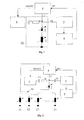
- a low-impedance analog multiplexer can be used to connect several sensor loops 11, 12, 13, 14 S1 can be installed, depending on the given address Adr to connect one of the sensor coils 11, 12, 13, 14 to the resonance circuit, such as this is shown in Fig. 2.
- Adr to connect one of the sensor coils 11, 12, 13, 14 to the resonance circuit, such as this is shown in Fig. 2.
- MOSFETs instead of an analog multiplexer or instead of high-frequency transistors it is also possible to use MOSFETs.
- the change in the ohmic coefficient R14 (T) of the sensor coil 14 can moreover can be used to determine the temperature.
- the in Fig. 2nd circuit shown can be modified (as shown in Fig. 3).
- the resistances R11 (T), R12 (T), R13 (T) ... R14 (T) denote the ohmic resistance of the Loops 11, 12, 13 and 14.
- a direct current I is impressed by the current source 33, which flows into the sensor loop 14 selected via S1 and Adr against the ground GND.
- the direct current causes a voltage drop U R14 (T) above the temperature-dependent resistance coefficient of the sensor loop R14 (T).
- the voltage drop across the inductance component is 14 0V.
- the voltage drop for the sensor specified with Adr can be tapped with a high impedance by the four- or three-wire measuring method via a switch S2, amplified with an amplifier 55 and passed on to the microprocessor 4 as an analog value.
- the microprocessor 4 calculates the current sensor loop temperature T from the 25 ° C. measurement value stored in the basic adjustment and the current measurement value using the known specific temperature coefficients.
- the inductive one is Coating sensor formed as part of a parallel resonance circuit.
- the Sensor is applied as a conductive layer on the top or bottom of the glass ceramic.
- the contact can be made via spring contacts or via conductively glued foil lines or via soldered broadband lines.
- Known conductor tracks are applied to the underside of the glass ceramic and usually have a width of 2 mm and a length of about 1 m, which indicates an electrical Resistance between 40 and Amounts to 200 ohms. The quality of the known sensors is therefore very low. With coating sensors Therefore, only elaborate functional principles such as the principle of inductive coupling applied.
- the series resonant circuit according to the invention according to Figures 1 to 3 remedies here.
- New coating materials and new coating techniques now allow it also to significantly reduce the resistance of the coating conductor tracks. It is possible, with a width of 2 mm and a length of 1 m now resistances of to realize a maximum of 3 ohms.
- Such sensor loops can be sent directly to the evaluation electronics connected, that means directly in a parallel resonance circuit be used.
- the pot detection is in this variant via a Change in the oscillator frequency realized.
- L (Pot) represents a sensor loop in FIG. 4, the inductance of which is set up by a Pot is reduced and thus affects the frequency in the LC oscillator circuit.
- CS is a fixed, high quality capacity.
- the eddy current losses in the base of the pot reduce the inductance L of the loop. This leads to an increase in the resonance frequency fr at the base of transistor Q1.
- a two-point controller above the cut-off frequency fg is the release signal for the energy supply to the radiator be generated.
Landscapes
- Chemical & Material Sciences (AREA)
- Engineering & Computer Science (AREA)
- Ceramic Engineering (AREA)
- Electronic Switches (AREA)
Abstract
Description
Claims (27)
- Kochstelle mit Glaskeramik, die zwecks Topferkennung einen induktiven Sensor aufweist,dessen Induktivität sich durch Wirbelstromverluste im Topf oder Kochgefäß verändert,der als Leiterbahn unterhalb oder oberhalb oder innerhalb der Glaskeramik mit einem vorbestimmten längenspezifischen Widerstand ausgeführt ist, undder Teil eines Serienschwingkreises ist, auf dem die Auswerteschaltung für die Topferkennung aufbaut.
- Kochstelle mit Glaskeramik nach Anspruch 1, dadurch gekennzeichnet, daß die Leiterbahn als beschichtete Leiterbahn ausgebildet ist.
- Kochstelle mit Glaskeramik, die zwecks Topferkennung einen induktiven Sensor aufweist,dessen Induktivität sich durch Wirbelstromverluste im Topf oder Kochgefäß verändert,der als beschichtete Leiterbahn unterhalb oder oberhalb oder innerhalb der Glaskeramik mit einem vorbestimmten längenspezifischen Widerstand ausgeführt ist, undder Teil eines Parallelschwingkreises ist, auf dem die Auswerteschaltung für die Topferkennung aufbaut.
- Kochstelle mit Glaskeramik nach Anspruch 3, dadurch gekennzeichnet, dass der ohmsche Widerstand des induktiven Beschichtungssensors nicht mehr als 3 Ohm beträgt und der induktive Sensor Teil eines Parallelschwingkreises ist.
- Kochstelle mit Glaskeramik nach Anspruch 2, dadurch gekennzeichnet, dass der längenspezifische Widerstand des induktiven Beschichtungssensors nicht mehr als 15 Ohm pro Meter beträgt und der induktive Sensor Teil eines Serienschwingkreises ist.
- Kochstelle mit Glaskeramik nach Anspruch 1, 2 oder 5, gekennzeichnet durch eine Vorrichtung (2) zur Änderung der Resonanzfrequenz des Serienschwingkreises (10) durch ein elektrisches Signal,eine erste Quelle (3) eines ersten periodischen Signals,eine zweite Quelle (4) eines zweiten Signals, wobei das zweite Signal zur Änderung der Resonanzfrequenz des Serienschwingkreises (10) eingesetzt wird,eine Vorrichtung zum Ermitteln des Resonanzzustandes im Serienschwingkreis (10), während dieser mit den ersten und zweiten Signalen gespeist wird; undeine Vorrichtung zum Analysieren des zweiten Signals anhand des ermittelten Resonanzzustands im Serienschwingkreis (10).
- Kochstelle mit Glaskeramik nach Anspruch 6, dadurch gekennzeichnet, dass die Vorrichtung (2) zur Änderung der Resonanzfrequenz des Serienschwingkreises (10) durch ein elektrisches Signal in Form eines kapazitiv wirkenden Elements (2) ausgeführt wird.
- Kochstelle mit Glaskeramik nach Anspruch 7, dadurch gekennzeichnet, dass das kapazitiv wirkende Element (2) eine Diode bzw. eine Kapazitätsdiode ist.
- Kochstelle mit Glaskeramik nach einem der Ansprüche 5 bis 8, dadurch gekennzeichnet, dass der Sensor (1) in Form einer induktiven Schleife mit einer oder mehrere Windungen ausgeführt ist.
- Kochstelle mit Glaskeramik nach einem der Ansprüche 5 bis 9, dadurch gekennzeichnet, dass die Vorrichtung zum Ermitteln des Resonanzzustandes im Serienschwingkreis (10) eine Vorrichtung (6) zum Ermitteln der Vorzeichenumkehr der Amplitude eines vom Serienschwingkreis (10) entnommenen Signals aufweist.
- Kochstelle mit Glaskeramik nach Anspruch 10, dadurch gekennzeichnet, dass die Vorrichtung zum Ermitteln des Resonanzzustandes im Serienschwingkreis (10) des weiteren eine Vorrichtung (5) zum Verstärken der Amplitude des vom Serienschwingkreis (10) entnommenen Signals aufweist.
- Kochstelle mit Glaskeramik nach einem der Ansprüche 10 oder 11, dadurch gekennzeichnet, dass die Vorrichtung (6) zum Ermitteln der Vorzeichenumkehr ein Rückkoppelungssignal an die Vorrichtung (4) zum Analysieren des zweiten elektrischen Signals liefert.
- Kochstelle mit Glaskeramik nach einem der Ansprüche 5 bis 12, dadurch gekennzeichnet, dass die Vorrichtung (4) zum Analysieren des zweiten elektrischen Signals ein Mikroprozessor ist.
- Kochstelle mit Glaskeramik nach einem der Ansprüche 10 bis 13, dadurch gekennzeichnet, dass die Vorrichtung (6) zum Ermitteln der Vorzeichenumkehr ein Differenzierer ist.
- Kochstelle mit Glaskeramik nach einem der Ansprüche 5 bis 14, dadurch gekennzeichnet, dass die Glaskeramik mit mehreren Sensoren (11, 12, 13, 14) ausgestattet ist.
- Kochstelle mit Glaskeramik nach Anspruch 15, dadurch gekennzeichnet, dass der Anschluss der Sensoren (11, 12, 13, 14) an den Serienschwingkreis mittels eines Multiplexers (S1) erfolgt.
- Kochstelle mit Glaskeramik nach Anspruch 15, dadurch gekennzeichnet, dass der Anschluss der Sensoren (11, 12, 13, 14) an den Serienschwingkreis mittels einer Vorrichtung mit mehreren HF-Transistoren erfolgt.
- Kochstelle mit Glaskeramik nach Anspruch 16 oder 17, dadurch gekennzeichnet, dass jedem Sensor (11, 12, 13, 14) eine Adresse (Adr) im Multiplexer (S1) oder in der Vorrichtung mit mehreren HF-Transistoren vorgegeben ist.
- Kochstelle mit Glaskeramik nach einem der Ansprüche 16 bis 18, dadurch gekennzeichnet, dass mindestens einer der Sensoren (11, 12, 13, 14) durch eine temperaturstabile feste Induktivität (14) ersetzt wird, wobei die Messwerte aus dem Serienschwingkreis mit der festen Induktivität (14) für eine Kalibrierung der verbliebenen Sensoren (11, 12, 13) verwendet werden.
- Kochstelle mit Glaskeramik nach Anspruch 4, dadurch gekennzeichnet, dass der induktive Sensor durch eine Siebdrucktechnik aufgebracht ist.
- Kochstelle mit Glaskeramik nach Anspruch 4 oder 20, dadurch gekennzeichnet, dass die elektrische Leitfähigkeit durch den Gehalt an Goldpartikeln oder eines anderen Edelmetalls in einem Kohlenstoffsubstrat bestimmt ist.
- Kochstelle mit Glaskeramik nach Anspruch 4 oder 20 oder 21, dadurch gekennzeichnet, dass die Schichtdicke des induktiven Sensors durch Aufgalvanisieren erhöht wird, wobei beispielsweise Gold an den schon vorhandenen Sensorstrukturen abgeschieden wird.
- Kochstelle mit Glaskeramik nach Anspruch 4 oder 20 bis 22, dadurch gekennzeichnet, dass die Breite der Leiterbahnen des induktiven Sensors weniger als 4 mm beträgt.
- Kochstelle mit Glaskeramik nach Anspruch 4 oder 20 bis 23, dadurch gekennzeichnet, dass die Betriebsfrequenz des Parallelresonanzkreises weniger als 30 MHz beträgt.
- Kochstelle mit Glaskeramik nach Anspruch 4 oder 20 bis 24, dadurch gekennzeichnet, dass oberhalb einer Grenzfrequenz (fg) ein Zweipunktregler ein Freigabesignal für die Energiezufuhr des Heizkörpers erzeugt.
- Verfahren zum Erkennen einer räumlichen Annäherung eines elektrisch leitenden Gegenstands mittels eines induktiv wirkenden Sensors, wobei der Sensor in einem Schwingkreis eingebaut ist, umfassend folgende Schritte:Einspeisen eines ersten periodischen Signals in den Schwingkreis;Änderung der Resonanzfrequenz (fr) des Schwingkreises durch Einspeisen eines zweiten Signals in den Schwingkreis;Feststellen eines Resonanzzustands in dem Schwingkreis; undAnalysieren des zweiten Signals anhand des festgestellten Resonanzzustands in dem Schwingkreis.
- Verfahren nach Anspruch 26, bei welchem der Sensor als beschichteter Sensor und der Schwingkreis als Serien- oder als Parallelschwingkreis ausgebildet werden.
Applications Claiming Priority (4)
| Application Number | Priority Date | Filing Date | Title |
|---|---|---|---|
| DE10142045 | 2001-08-28 | ||
| DE10142045 | 2001-08-28 | ||
| DE10232710A DE10232710B4 (de) | 2001-08-28 | 2002-07-18 | Kochstelle mit Kochgefässerkennungssystem |
| DE10232710 | 2002-07-18 |
Publications (2)
| Publication Number | Publication Date |
|---|---|
| EP1289339A2 true EP1289339A2 (de) | 2003-03-05 |
| EP1289339A3 EP1289339A3 (de) | 2005-09-28 |
Family
ID=26010008
Family Applications (1)
| Application Number | Title | Priority Date | Filing Date |
|---|---|---|---|
| EP02018103A Withdrawn EP1289339A3 (de) | 2001-08-28 | 2002-08-13 | Verfahren und Vorrichtung zum Erkennen einer räumlichen Annäherung elektrisch leitender Gegenstände und Verwendung der Vorrichtung als Kochgefässerkennungssystem |
Country Status (1)
| Country | Link |
|---|---|
| EP (1) | EP1289339A3 (de) |
Cited By (1)
| Publication number | Priority date | Publication date | Assignee | Title |
|---|---|---|---|---|
| US7791506B2 (en) | 2007-03-30 | 2010-09-07 | Zf Friedrichshafen Ag | Configurable networked user interface and switch pack |
Family Cites Families (2)
| Publication number | Priority date | Publication date | Assignee | Title |
|---|---|---|---|---|
| GB1418553A (en) * | 1973-06-26 | 1975-12-24 | Barnett J | Electric cookers |
| DE19700753C2 (de) * | 1997-01-11 | 2000-09-14 | Schott Glas | Kochfeld mit einer nicht-metallischen Kochplatte |
-
2002
- 2002-08-13 EP EP02018103A patent/EP1289339A3/de not_active Withdrawn
Cited By (1)
| Publication number | Priority date | Publication date | Assignee | Title |
|---|---|---|---|---|
| US7791506B2 (en) | 2007-03-30 | 2010-09-07 | Zf Friedrichshafen Ag | Configurable networked user interface and switch pack |
Also Published As
| Publication number | Publication date |
|---|---|
| EP1289339A3 (de) | 2005-09-28 |
Similar Documents
| Publication | Publication Date | Title |
|---|---|---|
| EP1797462B1 (de) | Sensor zur ortung metallischer objekte sowie verfahren zur auswertung von messsignalen eines solchen sensors | |
| DE3910297C2 (de) | ||
| DE4333419C2 (de) | Verfahren und Vorrichtung zur Schichtdickenmessung und Meßsonde für eine kombinierte Schichtdickenmeßvorrichtung | |
| EP2344849B1 (de) | VORRICHTUNG ZUR BESTIMMUNG UND/ODER ÜBERWACHUNG EINER PROZESSGRÖßE EINES MEDIUMS | |
| DE4119903C2 (de) | Verfahren und Vorrichtung zur Messung dünner Schichten | |
| DE102017100264A1 (de) | Vorrichtung und Verfahren zur in situ Kalibrierung eines Thermometers | |
| EP2539674A1 (de) | Sensor, system mit einem sensor und einem messobjekt sowie verfahren zur temperaturmessung mittels sensor | |
| DE3814131C2 (de) | Verfahren zum Messen des vom Abstand einer Steuerfahne abhängigen Anteils der Impedanz einer verlustbehafteten Spule und Vorrichtung zur Durchführung dieses Verfahrens | |
| EP1847019A1 (de) | Induktiver näherungsschalter basierend auf dem kopplungsfaktor-prinzip | |
| EP3637948B1 (de) | Heizvorrichtung und verfahren zur temperaturerfassung an einer heizvorrichtung | |
| DE10232710B4 (de) | Kochstelle mit Kochgefässerkennungssystem | |
| EP3245480B1 (de) | Induktive positionsbestimmung | |
| DE3815010C2 (de) | ||
| DE102006053023B4 (de) | Induktiver Näherungsschalter | |
| DE19646826A1 (de) | Vorrichtung und Verfahren zur Temperaturmessung und Topferkennung an Kochstellen | |
| EP3824323B1 (de) | Detektor zum detektieren von elektrisch leitfähigem material | |
| DE102004018630A1 (de) | Vorrichtung, Sensoranordnung und Verfahren zur kapazitiven Positionserfassung eines Zielobjekts | |
| DE102017128472B4 (de) | Induktiver Näherungsschalter und Verfahren zum Betreiben eines induktiven Näherungsschalters | |
| DE102017116027A1 (de) | Messgerät zur kapazitiven Messung eines Dielektrizitätswertes | |
| DE102020100675A1 (de) | Kapazitiver Drucksensor mit Temperaturerfassung | |
| DE102017128471B4 (de) | Induktiver Näherungsschalter und Verfahren zum Betreiben eines induktiven Näherungsschalters | |
| DE102011115922B4 (de) | Induktiver Sensor | |
| EP0167606B1 (de) | Vorrichtung zur kontinuierlichen messung der dicke | |
| DE102019128837B4 (de) | Induktiver Näherungssensor und Verfahren zum Anlernen von Targetklassen | |
| DE10042775A1 (de) | Topferkennung |
Legal Events
| Date | Code | Title | Description |
|---|---|---|---|
| PUAI | Public reference made under article 153(3) epc to a published international application that has entered the european phase |
Free format text: ORIGINAL CODE: 0009012 |
|
| 17P | Request for examination filed |
Effective date: 20020813 |
|
| AK | Designated contracting states |
Kind code of ref document: A2 Designated state(s): AT BE BG CH CY CZ DE DK EE ES FI FR GB GR IE IT LI LU MC NL PT SE SK TR Designated state(s): AT BE BG CH CY CZ DE DK EE ES FI FR GB GR IE IT LI LU MC NL PT SE SK TR |
|
| AX | Request for extension of the european patent |
Extension state: AL LT LV MK RO SI |
|
| PUAL | Search report despatched |
Free format text: ORIGINAL CODE: 0009013 |
|
| AK | Designated contracting states |
Kind code of ref document: A3 Designated state(s): AT BE BG CH CY CZ DE DK EE ES FI FR GB GR IE IT LI LU MC NL PT SE SK TR |
|
| AX | Request for extension of the european patent |
Extension state: AL LT LV MK RO SI |
|
| AKX | Designation fees paid |
Designated state(s): AT BE BG CH CY CZ DE DK EE ES FI FR GB GR IE IT LI LU MC NL PT SE SK TR |
|
| 17Q | First examination report despatched |
Effective date: 20090616 |
|
| RAP1 | Party data changed (applicant data changed or rights of an application transferred) |
Owner name: ZF FRIEDRICHSHAFEN AG |
|
| STAA | Information on the status of an ep patent application or granted ep patent |
Free format text: STATUS: THE APPLICATION IS DEEMED TO BE WITHDRAWN |
|
| 18D | Application deemed to be withdrawn |
Effective date: 20150303 |