EP1289332A2 - Vorrichtung und Verfahren zum Einrichten von Ersatzpfaden in einem Transportnetz - Google Patents
Vorrichtung und Verfahren zum Einrichten von Ersatzpfaden in einem Transportnetz Download PDFInfo
- Publication number
- EP1289332A2 EP1289332A2 EP02102012A EP02102012A EP1289332A2 EP 1289332 A2 EP1289332 A2 EP 1289332A2 EP 02102012 A EP02102012 A EP 02102012A EP 02102012 A EP02102012 A EP 02102012A EP 1289332 A2 EP1289332 A2 EP 1289332A2
- Authority
- EP
- European Patent Office
- Prior art keywords
- data connection
- optical
- network node
- network
- subscriber line
- Prior art date
- Legal status (The legal status is an assumption and is not a legal conclusion. Google has not performed a legal analysis and makes no representation as to the accuracy of the status listed.)
- Withdrawn
Links
- 238000000034 method Methods 0.000 title claims abstract description 8
- 230000003287 optical effect Effects 0.000 claims abstract description 85
- 230000011664 signaling Effects 0.000 claims abstract description 76
- 230000005540 biological transmission Effects 0.000 claims abstract description 14
- 239000013307 optical fiber Substances 0.000 claims description 62
- 238000004891 communication Methods 0.000 claims description 28
- 239000000835 fiber Substances 0.000 claims description 13
- 239000004020 conductor Substances 0.000 claims 2
- 238000012790 confirmation Methods 0.000 description 16
- 238000012546 transfer Methods 0.000 description 5
- 150000001875 compounds Chemical class 0.000 description 1
- 238000011161 development Methods 0.000 description 1
- 230000018109 developmental process Effects 0.000 description 1
- 238000012545 processing Methods 0.000 description 1
Images
Classifications
-
- H—ELECTRICITY
- H04—ELECTRIC COMMUNICATION TECHNIQUE
- H04J—MULTIPLEX COMMUNICATION
- H04J14/00—Optical multiplex systems
- H04J14/02—Wavelength-division multiplex systems
- H04J14/0227—Operation, administration, maintenance or provisioning [OAMP] of WDM networks, e.g. media access, routing or wavelength allocation
-
- H—ELECTRICITY
- H04—ELECTRIC COMMUNICATION TECHNIQUE
- H04J—MULTIPLEX COMMUNICATION
- H04J14/00—Optical multiplex systems
- H04J14/02—Wavelength-division multiplex systems
- H04J14/0227—Operation, administration, maintenance or provisioning [OAMP] of WDM networks, e.g. media access, routing or wavelength allocation
- H04J14/0241—Wavelength allocation for communications one-to-one, e.g. unicasting wavelengths
-
- H—ELECTRICITY
- H04—ELECTRIC COMMUNICATION TECHNIQUE
- H04J—MULTIPLEX COMMUNICATION
- H04J14/00—Optical multiplex systems
- H04J14/02—Wavelength-division multiplex systems
- H04J14/0287—Protection in WDM systems
-
- H—ELECTRICITY
- H04—ELECTRIC COMMUNICATION TECHNIQUE
- H04J—MULTIPLEX COMMUNICATION
- H04J14/00—Optical multiplex systems
- H04J14/02—Wavelength-division multiplex systems
- H04J14/0287—Protection in WDM systems
- H04J14/0293—Optical channel protection
- H04J14/0295—Shared protection at the optical channel (1:1, n:m)
-
- H—ELECTRICITY
- H04—ELECTRIC COMMUNICATION TECHNIQUE
- H04Q—SELECTING
- H04Q11/00—Selecting arrangements for multiplex systems
- H04Q11/0001—Selecting arrangements for multiplex systems using optical switching
- H04Q11/0062—Network aspects
-
- H—ELECTRICITY
- H04—ELECTRIC COMMUNICATION TECHNIQUE
- H04Q—SELECTING
- H04Q3/00—Selecting arrangements
- H04Q3/0016—Arrangements providing connection between exchanges
- H04Q3/0025—Provisions for signalling
-
- H—ELECTRICITY
- H04—ELECTRIC COMMUNICATION TECHNIQUE
- H04J—MULTIPLEX COMMUNICATION
- H04J14/00—Optical multiplex systems
- H04J14/02—Wavelength-division multiplex systems
- H04J14/0278—WDM optical network architectures
- H04J14/0284—WDM mesh architectures
-
- H—ELECTRICITY
- H04—ELECTRIC COMMUNICATION TECHNIQUE
- H04Q—SELECTING
- H04Q11/00—Selecting arrangements for multiplex systems
- H04Q11/0001—Selecting arrangements for multiplex systems using optical switching
- H04Q11/0062—Network aspects
- H04Q2011/0079—Operation or maintenance aspects
- H04Q2011/0081—Fault tolerance; Redundancy; Recovery; Reconfigurability
-
- H—ELECTRICITY
- H04—ELECTRIC COMMUNICATION TECHNIQUE
- H04Q—SELECTING
- H04Q11/00—Selecting arrangements for multiplex systems
- H04Q11/0001—Selecting arrangements for multiplex systems using optical switching
- H04Q11/0062—Network aspects
- H04Q2011/0088—Signalling aspects
-
- H—ELECTRICITY
- H04—ELECTRIC COMMUNICATION TECHNIQUE
- H04Q—SELECTING
- H04Q11/00—Selecting arrangements for multiplex systems
- H04Q11/0001—Selecting arrangements for multiplex systems using optical switching
- H04Q11/0062—Network aspects
- H04Q2011/009—Topology aspects
- H04Q2011/0092—Ring
-
- H—ELECTRICITY
- H04—ELECTRIC COMMUNICATION TECHNIQUE
- H04Q—SELECTING
- H04Q2213/00—Indexing scheme relating to selecting arrangements in general and for multiplex systems
- H04Q2213/1301—Optical transmission, optical switches
-
- H—ELECTRICITY
- H04—ELECTRIC COMMUNICATION TECHNIQUE
- H04Q—SELECTING
- H04Q2213/00—Indexing scheme relating to selecting arrangements in general and for multiplex systems
- H04Q2213/13141—Hunting for free outlet, circuit or channel
-
- H—ELECTRICITY
- H04—ELECTRIC COMMUNICATION TECHNIQUE
- H04Q—SELECTING
- H04Q2213/00—Indexing scheme relating to selecting arrangements in general and for multiplex systems
- H04Q2213/13146—Rerouting upon blocking/overload, rearrangement
-
- H—ELECTRICITY
- H04—ELECTRIC COMMUNICATION TECHNIQUE
- H04Q—SELECTING
- H04Q2213/00—Indexing scheme relating to selecting arrangements in general and for multiplex systems
- H04Q2213/13164—Traffic (registration, measurement,...)
-
- H—ELECTRICITY
- H04—ELECTRIC COMMUNICATION TECHNIQUE
- H04Q—SELECTING
- H04Q2213/00—Indexing scheme relating to selecting arrangements in general and for multiplex systems
- H04Q2213/13166—Fault prevention
-
- H—ELECTRICITY
- H04—ELECTRIC COMMUNICATION TECHNIQUE
- H04Q—SELECTING
- H04Q2213/00—Indexing scheme relating to selecting arrangements in general and for multiplex systems
- H04Q2213/13202—Network termination [NT]
-
- H—ELECTRICITY
- H04—ELECTRIC COMMUNICATION TECHNIQUE
- H04Q—SELECTING
- H04Q2213/00—Indexing scheme relating to selecting arrangements in general and for multiplex systems
- H04Q2213/13204—Protocols
Definitions
- the invention relates to an optical communication network according to the preamble of claim 1, a transmitting / receiving device for use in such optical communication network, as well as an optical Message transmission procedure according to the preamble of Claim 20.
- Optical communications networks generally have one first transmitting / receiving devices, from which on a data link optical signals with interposition several interconnected network node devices a second transmitting / receiving device can be transmitted.
- the network node devices can e.g. one each or several optical fibers can be connected to each other.
- WDM wavelength division multiplex or Wavelength division multiplexing
- a central control device in the communication network, e.g. a central control device be provided, which in the event of interference on the first data connection causes that of the first Transmitting / receiving device emitted optical signals henceforth via a second, to the first data connection different data connection are transmitted.
- the invention has for its object a novel optical News network, a new type of transceiver for use in an optical News network, as well as a new type of optical To provide messaging procedures.
- an optical message network in which optical signals are transmitted from a first transceiver via a first data connection to a second transceiver via a plurality of interconnected network node devices, characterized in that a second data connection is established between the first and second transmitting / receiving device, a data connection setup signaling signal is sent from the first transmitting / receiving device to a network node device connected to the first transmitting / receiving device, which contains information relating to the desired course of the second data connection.
- the second data connection should preferably be wholly or partially run disjoint to the first data connection (e.g. completely or partly via a different path, or via others Tubes, optical fiber bundles, optical fibers, etc.).
- the data transmission can quickly from the first data connection to the second (undisturbed) data connection can be switched.
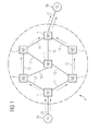
- an optical communication network or optical transport network (OTN) 8 according to a first Embodiment of the present invention a variety from network nodes 1, 2, 3, 4, 5, 6, 7 to that over a network of Optical fiber bundles 10, 11, 12, 13, 14, 15, 16, 17, 18, 19 are connected.
- a first runs from the first network node 1 Optical fiber bundle 11 to the second network node 2, from where from a second optical fiber bundle 12 to the third, and a third fiber optic bundle 13 to the fifth network node 5 runs.
- the fourth Network node 4 with a fourth optical fiber bundle 14 the third network node 3, via a fifth Optical fiber bundle 15 with the fifth network node 5, and via a sixth optical fiber bundle 16 with the seventh Network node 7 connected.
- 11, 12, 13, 14, 15, 16, 17, 18, 19 can be the individual Network node 1, 2, 3, 4, 5, 6, 7 e.g. each also over several parallel optical fiber bundles can be connected.
- Each optical fiber bundle 10, 11, 12, 13, 14, 15, 16, 17, 18, 19 has one or more optical waveguides.
- a first network subscriber line (TA) 9a is over a first optical fiber 20 (or via another Optical fiber bundle) at the first network node 1, and second network subscriber line (TB) 9b via a second Optical fiber 21 (or via another Optical fiber bundle) at the fourth network node 4 connected.
- WDM wavelength division multiplex or wavelength division multiplex
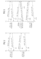
- first signaling signal S1 contains an identifier TB, the the target subscriber line (TB) 9b, or its optical Identifies network address.
- a network node control device (not shown) the one to be built Connection identifying (not yet assigned) Connection identifier (here: V1) selected, and in one Node storage device (also not shown) stored.
- the first network node N1 (or the network node control device) then selects one of the network node connected to the first network node 1 as the network node via which the connection to be continued (here: the second network node 2).
- an identifier assigned to this network node 2 is generated (or its network address) with assignment to the above Connection identifier V1 in the node storage device of the first network node 1 is stored.
- connection is successful until the second Subscriber line 9b has been established, this will be the fourth network node 4 from the second subscriber line 9b a corresponding one sent via the optical waveguide 21 Signaling signal communicated that this message via a another connection establishment confirmation signal signal forwards the third network node 3, which in turn is a Corresponding, directed to the second network node 2 Connection establishment confirmation signaling signal sent, which sends a corresponding signal to the first network node 1 sent.
- the subscriber line control device causes that - in addition to the above, via the path TA - N1 - N2 - N3 - N4 - TB-managed "work" data connection - another, via a "replacement” path “replacement” data connection to the second subscriber line 9b (in which Representation according to Figure 1 by dashed lines existing arrows).
- the "replacement" path should be disjoint to the above.
- "Working" path be, i.e. for the two connections, respectively different paths between the individual network nodes 1, 2, 3, 4, 5, 6, 7 can be used (path diversity - in FIG. 1 indicated by the arrows shown there).
- the "replacement" data connection should be on distinguish another way from the "work” data connection: For example, the path between two network nodes at both connections are identical, but should be two different, the same network nodes 1, 2, 3, 4, 5, 6, 7 connecting, in different tubes arranged optical fiber bundles 10, 11, 12, 13, 14, 15, 16, 17, 18, 19 or optical fibers can be used (duct diversity).
- Optical fiber bundle 10 11, 12, 13, 14, 15, 16, 17, 18, 19 are used, or e.g. the same Optical fiber bundle, but different in it contained optical fibers (fiber diversity).
- the "working" and the "Replacement" data connection e.g. also through each different buildings run (building diversity).
- control devices are the network nodes of the optical communication network 8, due to the specification of the "work" data connection or its identifier V1 to establish a "replacement" data connection in which a Data path is used that is disjoint to that at the "Working" data connection is used data path.
- the identifying "replacement" data connection to be established Connection identifier (here: V2) selected and in the corresponding network node storage device is stored.
- the first network node N1 (or the network node control device) then choose one with the first Network node 1 connected network node as that network node over which the "replacement" data connection continues should be (here: the sixth network node 6), and so, that the resulting "replacement” path disjunct to above-mentioned "Working" path is (i.e. here: that the "replacement" data connection via another network node is forwarded as the "working” data connection).
- the "Working" data connection used network nodes (here: the second network node 2) with assignment to the "work” data connection characteristic connection identifier V1 in the Network node storage device is stored.
- connection identifier V1 alternatively or additionally information regarding the tube used, or the fiber bundle used in each case or Optical fiber in the memory device of the first Network node stored, and for forwarding the "Replacement" data connection for this different tubes, Optical fiber bundle or optical fiber used).
- the identifier (or its network address) is assigned to above-mentioned Connection identifier V2 in the network node storage device of the first network node 1 is stored.
- the node controller causes that from the first node 1 from the Optical fiber bundle 10 a the above.
- Signaling signal S3 corresponding further substitute connection establishment request signaling signal at the selected sixth network node 6 is sent, which among other things the above the destination subscriber line (TB) identifier TB, which is the "replacement" data link characteristic connection identifier V2, and which identifies the "working" data connection established ID contains V1.
- TB destination subscriber line
- connection identifier V2 is in a (not shown) Storage device of the sixth network node 6 is stored. Then in a (also not shown) Node control device in a similar manner as in first network node 1 to continue the "replacement" data connection one of the sixth network node 6 connected network nodes (here: the seventh network node 7) selected in such a way that the resultant "Replacement" path disjoint to the above "Work" path is (i.e. here: that the "replacement" data connection over another Network node is forwarded as the "working" data connection). For this purpose, it is first checked whether the Connection identifier identifying "work" data connection V1 is stored in the network node storage device (i.e. the "working" data link over the sixth Network node 6 is performed), and if so, via which Network node the "working" data connection from network node 6 was forwarded. The corresponding network node is then not when switching on the "replacement” data connection used.
- the identifier assigned to the selected seventh network node 7 (or its network address) is assigned to the above
- Connection identifier V2 in the network node storage device of the sixth network node 6 is stored.
- the node controller causes that from the sixth node 6 to the selected seventh network node 7 a the above.
- Signaling signal S3 corresponding further Substitute connection establishment request signaling signal sent will, etc.
- connection identifiers V1, V2 are sent when the actual user data through the subscriber line 9a Identification of the connection to be used in each case used.
- the user data can also be given without specification the connection identifiers V1, V2 are transmitted, since the present switching circuit implicit assignment between a compound and a wavelength on one certain optical fibers is given.
- the above "Replacement" data connection can e.g. only from Subscriber line 9a are used for data transmission, if there is interference on the "working" data connection (or the interference on the "work” data link is too large become). This makes it possible to be on the “working” data connection occurring (strong) disturbances the Data transfer quickly to the "replacement” data connection switch.
- Alternatively, e.g. in parallel across the "Working" - and the “replacement” data connection are the same Transferring data, and each at the time of transfer occurring bit error rates are measured. Based on the then occurring bit error rates are then decided whether on the second subscriber line 9b via the "work", or the data sent over the "replacement" data connection should be considered valid.
- second embodiment of the Invention is according to an optical communication network similar to the message network 8 shown in FIG. 1 built up.
- this (connection establishment request) signaling signal S11 contain the identifier TB, which is the destination subscriber line (TB) 9b, or its optical network address.
- the first network node 1 After the first network node 1 has Call setup request signaling signal S11 has received from one (Not shown) control device of the first Network node 1 identifying the connection to be set up Connection identifier (here: V1) selected, and in a (not network node storage device shown. Thereupon the connection is made by means of corresponding further (Connection establishment request) signaling signals to the second Network node 2, from there to the third and fourth network node 3, 4, and finally to the second subscriber line 9b advanced.
- V1 Connection identifier
- This is controlled by a (not shown) Control device of the first subscriber line 9a in a subscriber line storage device (not shown) stored.
- the subscriber line control device causes that - in addition to the above, via the path TA - N1 - N2 - N3 - N4 - TB managed - "working" data connection another, via a "replacement” path "replacement" data connection to the second subscriber line 9b (in the Representation according to Figure 1 by dashed lines existing arrows).
- the "replacement” path should be disjoint to the above.
- "Working” path be (path diversity).
- Message network according to the second embodiment not able to independently based on the specification of the the "working" data connection identifier V1 independently one for "Working" data connection disjoint "replacement" data connection (e.g. because the "replacement" data connection is via a path of another network operator is to be run, and / or because, unlike the first Embodiment in the decentralized communication network, e.g. in assigned to the individual network nodes Storage facilities, information regarding the for the "Working" data connection path used, Fiber bundle, fiber optic, etc. are saved).
- the (resource request) signaling signal S13 includes which identifies the "working" data connection established ID V1 included.
- the first network node 1 receives the resource request signaling signal S13, are from its control device the above stored in the node storage device Information regarding the from the "working" data connection used resources (e.g. the identifiers of the Network nodes over which the "work" path is led, or their optical network addresses).
- the controller of the first Subscriber connection 9a Upon receipt of the resource notification signaling signal S14 is controlled by the controller of the first Subscriber connection 9a from the network node identifier list removed the identifier assigned to the network node to which the first subscriber line 9a is connected (here: the first network node 1), and the identifier that is assigned to the network node to which the second Subscriber connection 9a is connected (here: the fourth Network node 4).
- signaling signal S15 contains the identifier TB, which is the destination subscriber line (TB) 9b, or its optical network address identifies, as well as when establishing the "replacement" data connection resources to avoid (here: the by the second and third network nodes 2, 3 marked "Working" path).
- the "replacement" data connection to be set up characteristic connection identifier here: V2
- the first network node N1 or the network node control device
- the node controller causes that from the first network node 1 to one of the above Signaling signal S15 corresponding further Substitute connection establishment request signaling signal to selected sixth network node 6 is sent, which u.a. the above identifying the destination subscriber line (TB) Identifier TB, which identifies the "replacement" data connection Connection identifier V2, as well as when establishing the "replacement" data connection contains resources to avoid.
- TB subscriber line
- a network node connected to the sixth network node 6 as selected the network node over which the "replacement" data connection to be continued here: the seventh Network node 7
- the resulting resulting "replacement” path disjoint to the above "Work" path is (i.e. here: that the next network node used is not in the above List of network nodes 2, 3 to be avoided included is).
- first Subscriber connection 9a which i.a. the above Contains connection identifier V2.
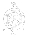
- an optical communication network or optical transport network (OTN) 108 according to a third Embodiment of the present invention several Network node 101, 102, 103, 104, 105, 106, 107 and one Many other network nodes, not shown here.
- the network nodes 101, 102, 103, 104, 105, 106, 107 are over a network of one or more at a time
- Optical fiber bundles 110, 111, 112, 113, 114, 115, 116, 117, 118, 119 connected to each other.
- each Optical fiber bundle 110, 111, 112, 113, 114, 115, 116, 117, 118, 119 has one or more optical waveguides.
- a first network subscriber line (TA) 109a is over one first optical waveguide 120 at the first network node 101, and a second network subscriber line (TB) 109b via one second optical waveguide 121 at the fourth network node 104 connected. Furthermore - in contrast to the above explained first and second embodiment - the first network subscriber line (TA) 109a additionally via a third optical fiber 122 to the sixth Network node 106, and the second network subscriber line (TB) 109b via a fourth optical fiber 123 to the third Network node 103 connected.
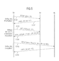
- signaling signal S101 is an identifier TB contain the destination subscriber line (TB) 109b, or identifies its optical network address.
- the connection After the first network node 101 has the above-mentioned Call setup request signaling signal S101 received from one (Not shown) control device of the first Network node 101 a the connection to be set up characteristic connection identifier (here: V1) selected, and in a node storage device (not shown) stored. Then the connection is made using corresponding further (connection establishment request) Signaling signals to the second and third network nodes 102, 103, and from there to the second subscriber line 109b advanced.
- V1 characteristic connection identifier
- the first subscriber line 109a which i.a. the above Contains connection identifier V1.
- This is under the control of a (not shown) Control device of the first subscriber line 109a in a subscriber line storage device (not shown) stored.
- the subscriber line control device causes that - in addition to the above, via the path TA - N1 - N2 - N3 - TB maintained "work" data connection - another, about a "replacement” path to "replacement” data connection second subscriber line 109b (in which Representation according to Figure 1 by dashed lines existing arrows).
- the "replacement” path should be disjoint to the above.
- "Working” path be (path diversity).
- TA Subscriber connection
- N1 the first network node
- This is used in the memory device of the first Node 101 (or elsewhere in the communications network) stored information relating to the "working" data connection used resources (i.e. regarding the each used "work” path, or the respectively used tubes, fiber optic bundles, Fiber optic cables, etc.).
- the (resource request) signaling signal S103 includes which identifies the "working" data connection established ID V1 included.
- the first network node 101 receives the resource request signaling signal S103, will be from its control device the above stored in the node storage device Information regarding the from the "working" data connection used resources (e.g. the identifiers of the Network nodes over which the "work" path is led, or their optical network addresses).
- Information regarding the from the "working" data connection used resources e.g. the identifiers of the Network nodes over which the "work" path is led, or their optical network addresses).
- Signaling signal S105 contains the identifier TB, which the Target subscriber line (TB) 109b, or its optical Identifies network address, as well as when establishing the "replacement" data connection resources to avoid (here: the by the first, second and third network nodes 101, 102, 103 marked "work" path).
- the sixth network node 106 After receiving the replacement connection establishment request signaling signal S105 is in the sixth network node 106 of the corresponding network node control device identifying "replacement" data connection to be established Connection identifier (here: V2) generated, and in the node storage device stored.
- the sixth network node 106 (or the network node control device) then selects one of the network node connected to the sixth network node 106 as the network node via which the "replacement" data connection to be continued (here: the seventh Network node 107), and in such a way that the resulting resulting "replacement" path disjoint to the above "Work" path is (i.e. here: that the next network node used is not in to the list obtained from the first subscriber line 109a avoiding network node 101, 102, 103 is included).
- the node controller of the sixth network node 106 causes the sixth Network node 106 from a the above.
- Signaling signal S105 corresponding further substitute connection establishment request signaling signal at the selected seventh network node 107 is sent, which among other things the above the destination subscriber line (TB) identifier TB, which is the "replacement" data link characteristic connection identifier V2, and those to be avoided when establishing the "replacement" data connection Contains resources.
- TB destination subscriber line
- node control device of the seventh network node 107 corresponding manner as in the sixth network node 106 Continuation of the "replacement" data connection with the seventh node 107 connected node than that Network node selected through which the "replacement" data connection to be continued (here: the fourth network node 104), again in such a way that the resultant "Working" path disjoint to the above "Work” path is (i.e. here: that the next network node used is not in the above-mentioned Contain list of network nodes 101, 102, 103 to be avoided is).
- connection is successful until the second Subscriber line 109b built up, this will be the fourth network node 104 from the second subscriber line 109b communicated via a corresponding signaling signal, the this notice of another alternate connection setup acknowledge signaling signal to the seventh network node 107 forwards a corresponding one to the sixth network node 106 directed substitute connection confirmation signaling signal sent.
- This is under the control of the Subscriber line controller of the first Subscriber line 109a in the subscriber line storage device saved, and - when sending the actual user data - to identify the respective using the connection used.
Landscapes
- Engineering & Computer Science (AREA)
- Computer Networks & Wireless Communication (AREA)
- Signal Processing (AREA)
- Data Exchanges In Wide-Area Networks (AREA)
- Optical Communication System (AREA)
Abstract
Description
Claims (22)
- Optisches Nachrichtennetzwerk (8), bei welchem über eine erste Datenverbindung optische Signale von einer ersten Sende-/Empfangseinrichtung (9a) über mehrere miteinander verbundene Netzknoteneinrichtungen (1, 2, 3, 4, 5, 6, 7) an eine zweite Sende-/Empfangseinrichtung (9b) übermittelt werden,
dadurch gekennzeichnet, dass zum Aufbau einer zweiten Datenverbindung zwischen erster und zweiter Sende-/Empfangseinrichtung (9a, 9b) von der ersten Sende-/Empfangseinrichtung (9a) ein Datenverbindungsaufbau-Signalisiersignal (S3, S15) an eine mit der ersten Sende-/Empfangseinrichtung (9a) verbundene Netzknoteneinrichtung (1) gesendet wird, in welchem Informationen bezüglich des gewünschten Verlaufs der zweiten Datenverbindung enthalten sind. - Optisches Nachrichtennetzwerk (8), bei welchem die Informationen eine die erste Datenverbindung kennzeichnende Kennung (V1) enthalten.
- Optisches Nachrichtennetzwerk (8) nach Anspruch 2, bei welchem durch die Informationen gekennzeichnet wird, daß die zweite Datenverbindung ganz oder teilweise disjunkt zur ersten Datenverbindung verlaufen soll.
- Optisches Nachrichtennetzwerk (8) nach Anspruch 3, bei welchem die zweite Datenverbindung ganz oder teilweise über einen anderen Pfad verlaufen soll, als die erste Datenverbindung.
- Optisches Nachrichtennetzwerk (8) nach Anspruch 3 oder 4, bei welchem die zweite Datenverbindung ganz oder teilweise über andere Lichtwellenleiterbündel verlaufen soll, als die erste Datenverbindung.
- Optisches Nachrichtennetzwerk (8) nach Anspruch 3, 4, oder 5, bei welchem die zweite Datenverbindung ganz oder teilweise über andere Lichtwellenleiter verlaufen soll, als die erste Datenverbindung.
- Optisches Nachrichtennetzwerk (8) nach Anspruch 1, bei welchem die Informationen Informationen bezüglich eines von der zweiten Datenverbindung zu vermeidenden, von der ersten Datenverbindung genutzten Pfads enthalten.
- Optisches Nachrichtennetzwerk (8) nach Anspruch 1 oder 7, bei welchem die Informationen Informationen bezüglich von der zweiten Datenverbindung zu vermeidender, von der ersten Datenverbindung genutzter Lichtwellenleiterbündel oder Lichtwellenleiter enthalten.
- Optisches Nachrichtennetzwerk (8) nach einem der vorhergehenden Ansprüche, bei welchem die erste Sende-/Empfangseinrichtung eine Teilnehmeranschlußeinrichtung ist.
- Optisches Nachrichtennetzwerk (8) nach Anspruch 9, bei welchem die Teilnehmeranschlußeinrichtung an eine einzige Netzknoteneinrichtung (1) gekoppelt ist.
- Optisches Nachrichtennetzwerk (8) nach Anspruch 9, bei welchem die Teilnehmeranschlußeinrichtung an mehrere Netzknoteneinrichtungen (101, 106) gekoppelt ist.
- Optisches Nachrichtennetzwerk (8) nach einem der vorhergehenden Ansprüche, bei welchem die zweite Sende-/Empfangseinrichtung eine zweite Teilnehmeranschlußeinrichtung ist.
- Optisches Nachrichtennetzwerk (8) nach Anspruch 12, bei welchem die zweite Teilnehmeranschlußeinrichtung an eine einzige Netzknoteneinrichtung (4) gekoppelt ist.
- Optisches Nachrichtennetzwerk (8) nach Anspruch 12, bei welchem die zweite Teilnehmeranschlußeinrichtung an mehrere Netzknoteneinrichtungen (103, 104) gekoppelt ist.
- Optisches Nachrichtennetzwerk (8) nach einem der vorhergehenden Ansprüche, bei welchem die zweite Datenverbindung als Ersatzdatenverbindung verwendet wird.
- Optisches Nachrichtennetzwerk (8) nach Anspruch 15, bei welchem die zweite Datenverbindung dann als Ersatzdatenverbindung verwendet wird, wenn auf der ersten Datenverbindung Störungen oder zu starke Störungen aufreten.
- Optisches Nachrichtennetzwerk (8) nach einem der vorhergehenden Ansprüche, bei welchem die über die erste und zweite Datenverbindung übertragenen Signale wellenlängengemultiplexte optische Signale sind.
- Optisches Nachrichtennetzwerk (8) nach einem der vorhergehenden Ansprüche, bei welchem die erste Sende-/Empfangseinrichtung (9a) das Datenverbindungsaufbau-Signalisiersignal (S1) über den gleichen Lichtwellenleiter (20) oder das gleiche Lichtwellenleiterbündel überträgt, wie von ihm ausgesendete Nutzdaten-Signale.
- Sende-/Empfangseinrichtung (9a), insbesondere Teilnehmeranschlußeinrichtung, welche so ausgestaltet und eingerichtet ist, daß sie als erste Sende-/Empfangseinrichtung in einem optischen Nachrichtennetzwerk (8) gemäß einem der Ansprüche 1 bis 18 verwendbar ist.
- Optisches Nachrichtenübermittlungsverfahren, wobei über eine erste Datenverbindung optische Signale von einer ersten Sende-/Empfangseinrichtung (9a) über mehrere miteinander verbundene Netzknoteneinrichtungen (1, 2, 3, 4, 5, 6, 7) an eine zweite Sende-/Empfangseinrichtung (9b) übermittelt werden, dadurch gekennzeichnet, dass das Verfahren den Schritt aufweist:Senden eines Datenverbindungsaufbau-Signalisiersignals (S1) an eine mit der ersten Sende-/Empfangseinrichtung (9a) verbundene Netzknoteneinrichtung (1) zum Aufbau einer zweiten Datenverbindung zwischen erster und zweiter Sende-/Empfangseinrichtung (9a, 9b), in welchem Informationen bezüglich des gewünschten Verlaufs der zweiten Datenverbindung enthalten sind.
- Optisches Nachrichtennetzwerk (8) nach einem der Ansprüche 1 bis 17, bei welchem die erste Sende-/Empfangseinrichtung (9a) das Datenverbindungsaufbau-Signalisiersignal (S1) über einen anderen Leiter überträgt, als von ihm ausgesendete Nutzdaten-Signale, insbesondere als elektrisches Signalisiersignal über einen elektrischen Leiter, oder als optsiches Signalisiersignal über einen weiteren Lichtwellenleiter.
- Optisches Nachrichtennetzwerk (8) nach einem der Ansprüche 1 bis 18, oder nach Anspruch 21, bei welchem mit Hilfe eines weiteren Datenverbindungsaufbau-Signalisiersignals (S13) eine Liste von von der ersten Datenverbindung genutzten Netzelementen, insbesondere Netzknoteneinrichtungen, Lichtwellenleiter, oder Lichtwellenleiterbündel abgefragt wird.
Applications Claiming Priority (2)
| Application Number | Priority Date | Filing Date | Title |
|---|---|---|---|
| DE10139156A DE10139156B4 (de) | 2001-08-09 | 2001-08-09 | Optisches Übertragungssystem und Verfahren zum Einrichten einer Ersatzdatenverbindung in einem Transportnetz für Dual-Homing |
| DE10139156 | 2001-08-09 |
Publications (2)
| Publication Number | Publication Date |
|---|---|
| EP1289332A2 true EP1289332A2 (de) | 2003-03-05 |
| EP1289332A3 EP1289332A3 (de) | 2008-04-30 |
Family
ID=7694919
Family Applications (1)
| Application Number | Title | Priority Date | Filing Date |
|---|---|---|---|
| EP02102012A Withdrawn EP1289332A3 (de) | 2001-08-09 | 2002-07-09 | Vorrichtung und Verfahren zum Einrichten von Ersatzpfaden in einem Transportnetz |
Country Status (3)
| Country | Link |
|---|---|
| US (1) | US20030031213A1 (de) |
| EP (1) | EP1289332A3 (de) |
| DE (1) | DE10139156B4 (de) |
Families Citing this family (1)
| Publication number | Priority date | Publication date | Assignee | Title |
|---|---|---|---|---|
| DE10139155C2 (de) * | 2001-08-09 | 2003-07-24 | Siemens Ag | Signalisierungs-Proxy-Einrichtung zum automatischen Aufbau von Ersatzpfaden in optischen Netzen |
Family Cites Families (11)
| Publication number | Priority date | Publication date | Assignee | Title |
|---|---|---|---|---|
| US6487626B2 (en) | 1992-09-29 | 2002-11-26 | Intel Corporaiton | Method and apparatus of bus interface for a processor |
| US5610904A (en) * | 1995-03-28 | 1997-03-11 | Lucent Technologies Inc. | Packet-based telecommunications network |
| US6088141A (en) * | 1995-06-26 | 2000-07-11 | Telefonaktiebolaget Lm Ericsson | Self-healing network |
| US5815490A (en) * | 1995-11-20 | 1998-09-29 | Nec America, Inc. | SDH ring high order path management |
| US6335927B1 (en) * | 1996-11-18 | 2002-01-01 | Mci Communications Corporation | System and method for providing requested quality of service in a hybrid network |
| US6904110B2 (en) * | 1997-07-31 | 2005-06-07 | Francois Trans | Channel equalization system and method |
| US6111881A (en) * | 1997-12-29 | 2000-08-29 | Nortel Networks Corporation | Signaling protocol for rerouting ATM connections in PNNI environments |
| US6272107B1 (en) * | 1998-05-12 | 2001-08-07 | 3Com Corporation | Method of path restoration in an ATM network utilizing point to point switched virtual circuits |
| DE19845331A1 (de) * | 1998-10-01 | 2000-04-06 | Siemens Ag | Verfahren und Vorrichtung zur Verkehrswegebestimmung in einem Kommunikations- oder Datennetz oder einem Netz aus Kommunikations- und Datennetz |
| US6209039B1 (en) * | 1998-10-16 | 2001-03-27 | Mci Worldcom, Inc. | Method and apparatus for providing an interface between a plurality of frame relay networks |
| US7006505B1 (en) * | 2000-10-23 | 2006-02-28 | Bay Microsystems, Inc. | Memory management system and algorithm for network processor architecture |
-
2001
- 2001-08-09 DE DE10139156A patent/DE10139156B4/de not_active Expired - Fee Related
-
2002
- 2002-07-09 EP EP02102012A patent/EP1289332A3/de not_active Withdrawn
- 2002-08-09 US US10/216,149 patent/US20030031213A1/en not_active Abandoned
Non-Patent Citations (5)
| Title |
|---|
| MANCHESTER J ET AL: "THE EVOLUTION OF TRANSPORT NETWORK SURVIVABILITY" IEEE COMMUNICATIONS MAGAZINE, IEEE SERVICE CENTER,NEW YORK, NY, US, Bd. 37, Nr. 8, August 1999 (1999-08), Seiten 44-51, XP000835317 ISSN: 0163-6804 * |
| ORNAN (ORI) GERSTEL ET AL: "Optical Layer Survivability-An Implementation Perspective" IEEE JOURNAL ON SELECTED AREAS IN COMMUNICATIONS, IEEE SERVICE CENTER, PISCATAWAY, US, Bd. 18, Nr. 10, Oktober 2000 (2000-10), XP011055223 ISSN: 0733-8716 * |
| RAMAMURTHY S ET AL: "SURVIVABLE WDM MESH NETWORKS, PART II - RESTORATION" ICC '99. 1999 IEEE INTERNATIONAL CONFERENCE ON COMMUNICATIONS. CONFERENCE RECORD. VANCOUVER, CA, JUNE 6 - 10, 1999, IEEE INTERNATIONAL CONFERENCE ON COMMUNICATIONS, NEW YORK, NY : IEEE, US, Bd. VOL. 3, 6. Juni 1999 (1999-06-06), Seiten 2023-2030, XP000903720 ISBN: 0-7803-5285-8 * |
| RAMAMURTHY S ET AL: "Survivable WDM mesh networks. Part I-Protection" INFOCOM '99. EIGHTEENTH ANNUAL JOINT CONFERENCE OF THE IEEE COMPUTER AND COMMUNICATIONS SOCIETIES. PROCEEDINGS. IEEE NEW YORK, NY, USA 21-25 MARCH 1999, PISCATAWAY, NJ, USA,IEEE, US, Bd. 2, 21. März 1999 (1999-03-21), Seiten 744-751, XP010323803 ISBN: 0-7803-5417-6 * |
| YINGHUA YE ET AL: "On Joint Protection/Restoration in IP-Centric DWDM-Based Optical Transport Networks" IEEE COMMUNICATIONS MAGAZINE, IEEE SERVICE CENTER, PISCATAWAY, US, Bd. 38, Nr. 6, Juni 2000 (2000-06), Seiten 174-183, XP011091311 ISSN: 0163-6804 * |
Also Published As
| Publication number | Publication date |
|---|---|
| US20030031213A1 (en) | 2003-02-13 |
| DE10139156A1 (de) | 2003-03-13 |
| EP1289332A3 (de) | 2008-04-30 |
| DE10139156B4 (de) | 2007-02-01 |
Similar Documents
| Publication | Publication Date | Title |
|---|---|---|
| DE60031055T2 (de) | Optische Paket-Weiterleitung in einem Netzwerksystem basiert auf optische Etikett-Kopplungstechnik | |
| EP0457863B1 (de) | Übertragungseinrichtung mit einer optischen übertragungsstrecke | |
| EP2034668B1 (de) | Hochverfügbares Kommunikationssystem | |
| DE3902243C2 (de) | ||
| EP0998798A1 (de) | Verfahren und anordnung zur datenübertragung im wellenlängenmultiplexverfahren in einem optischen ringnetz | |
| EP0118767A2 (de) | Verfahren für eine Fernmelde-, insbesondere Fernsprechnebenstellenanlage mit einem Datenübertragungsleitungssystem, insbesondere mit einem optischen Datenübertragungsleitungssystem | |
| EP2594054B1 (de) | Verkehrsmittel zur kabelgebundenen datenübertragung zwischen zwei lösbar miteinander verbundenen fahrzeugen | |
| DE69634149T2 (de) | Optischer knoten in einem optischen busnetz | |
| DE10142372B4 (de) | Vorrichtung und Verfahren zum Wiederherstellen von Verbindungen in automatisch schaltbaren optischen Netzen | |
| DE10139155C2 (de) | Signalisierungs-Proxy-Einrichtung zum automatischen Aufbau von Ersatzpfaden in optischen Netzen | |
| EP0729247A2 (de) | Verfahren und Anordnung zur optimalen Nutzung der Übertragungskapazität in synchronen bidirektionalen Ringnetzen | |
| DE69321391T2 (de) | Verfahren zur dezentralen Steuerung der Kommunikationsleitweglenkung im Paketvermittlungsnetz | |
| DE4318732A1 (de) | Optisches Netz | |
| DE10139156B4 (de) | Optisches Übertragungssystem und Verfahren zum Einrichten einer Ersatzdatenverbindung in einem Transportnetz für Dual-Homing | |
| DE10243850A1 (de) | Verfahren zur Übertragung von Datentelegrammen in einem geschalteten, zyklischen Kommunikationssystem | |
| EP1313347A1 (de) | Routing in Übertragungsnetzen | |
| DE10343615A1 (de) | Netzknoten für ein optisches Nachrichtenübertragungsnetz | |
| DE10037969C2 (de) | Verfahren zur Erkennung einer flexiblen Vernetzung von Baugruppen bei beliebiger Netztopologie sowie zum Informationsaustausch zwischen solchen Baugruppen | |
| EP0105212A2 (de) | Schaltungsanordnung zum Übertragen von Signalen zwischen Teilnehmeranschlussleitungen und wenigstens einer Übertragungsleitung einer dienstintegrierten Fernmeldeanlage | |
| EP0162994A1 (de) | Kommunikationsnetz und dessen Verwendung | |
| EP0631455A1 (de) | Verfahren zum Aufrechterhalten von virtuellen Verbindungen bei einem zumindest teilweisen Ausfall von Verbindungswegen | |
| EP0984658B1 (de) | Telekommunikationssystem mit Vermittlungseinrichtung und Datenkonzentrator für den Zugang zum Internet | |
| DE60018779T2 (de) | Signalisierung von fehlern in nachrichtenübertragungsnetzwerken | |
| EP1283620B1 (de) | Vorrichtung und Verfahren zur Client-Registrierung in einem automatisch schaltbaren optischen Netz | |
| DE10131210B4 (de) | Optisches Übertragungssystem mit bidirektionalen Verbindungspfaden und Verfahren zum Einrichten mindestens eines bidirektionalen Verbindungspfades |
Legal Events
| Date | Code | Title | Description |
|---|---|---|---|
| PUAI | Public reference made under article 153(3) epc to a published international application that has entered the european phase |
Free format text: ORIGINAL CODE: 0009012 |
|
| AK | Designated contracting states |
Kind code of ref document: A2 Designated state(s): AT BE BG CH CY CZ DE DK EE ES FI FR GB GR IE IT LI LU MC NL PT SE SK TR Designated state(s): AT BE BG CH CY CZ DE DK EE ES FI FR GB GR IE IT LI LU MC NL PT SE SK TR |
|
| AX | Request for extension of the european patent |
Extension state: AL LT LV MK RO SI |
|
| RAP1 | Party data changed (applicant data changed or rights of an application transferred) |
Owner name: NOKIA SIEMENS NETWORKS GMBH & CO. KG |
|
| RAP3 | Party data changed (applicant data changed or rights of an application transferred) |
Owner name: NOKIA SIEMENS NETWORKS S.P.A. |
|
| RAP3 | Party data changed (applicant data changed or rights of an application transferred) |
Owner name: NOKIA SIEMENS NETWORKS GMBH & CO. KG |
|
| PUAL | Search report despatched |
Free format text: ORIGINAL CODE: 0009013 |
|
| AK | Designated contracting states |
Kind code of ref document: A3 Designated state(s): AT BE BG CH CY CZ DE DK EE ES FI FR GB GR IE IT LI LU MC NL PT SE SK TR |
|
| AX | Request for extension of the european patent |
Extension state: AL LT LV MK RO SI |
|
| RIC1 | Information provided on ipc code assigned before grant |
Ipc: H04J 14/02 20060101ALI20080327BHEP Ipc: H04Q 11/00 20060101AFI20030109BHEP |
|
| 17P | Request for examination filed |
Effective date: 20081030 |
|
| 17Q | First examination report despatched |
Effective date: 20081125 |
|
| AKX | Designation fees paid |
Designated state(s): DE FR GB IT |
|
| STAA | Information on the status of an ep patent application or granted ep patent |
Free format text: STATUS: THE APPLICATION IS DEEMED TO BE WITHDRAWN |
|
| 18D | Application deemed to be withdrawn |
Effective date: 20090606 |