EP1289286A2 - Automatic return to a high-definition mode after guide demonstration - Google Patents
Automatic return to a high-definition mode after guide demonstration Download PDFInfo
- Publication number
- EP1289286A2 EP1289286A2 EP02292006A EP02292006A EP1289286A2 EP 1289286 A2 EP1289286 A2 EP 1289286A2 EP 02292006 A EP02292006 A EP 02292006A EP 02292006 A EP02292006 A EP 02292006A EP 1289286 A2 EP1289286 A2 EP 1289286A2
- Authority
- EP
- European Patent Office
- Prior art keywords
- program guide
- mode
- source
- demonstration
- switch
- Prior art date
- Legal status (The legal status is an assumption and is not a legal conclusion. Google has not performed a legal analysis and makes no representation as to the accuracy of the status listed.)
- Withdrawn
Links
- 238000000034 method Methods 0.000 claims description 12
- 239000011159 matrix material Substances 0.000 description 7
- 238000006243 chemical reaction Methods 0.000 description 3
- 238000010586 diagram Methods 0.000 description 2
- 238000004040 coloring Methods 0.000 description 1
- 238000004891 communication Methods 0.000 description 1
- 239000002131 composite material Substances 0.000 description 1
- 238000001914 filtration Methods 0.000 description 1
- 230000002452 interceptive effect Effects 0.000 description 1
- 239000000463 material Substances 0.000 description 1
- 238000012544 monitoring process Methods 0.000 description 1
- 230000000750 progressive effect Effects 0.000 description 1
- 230000002123 temporal effect Effects 0.000 description 1
- 230000001960 triggered effect Effects 0.000 description 1
Images

Classifications
-
- H—ELECTRICITY
- H04—ELECTRIC COMMUNICATION TECHNIQUE
- H04N—PICTORIAL COMMUNICATION, e.g. TELEVISION
- H04N21/00—Selective content distribution, e.g. interactive television or video on demand [VOD]
- H04N21/40—Client devices specifically adapted for the reception of or interaction with content, e.g. set-top-box [STB]; Operations thereof
- H04N21/47—End-user applications
-
- H—ELECTRICITY
- H04—ELECTRIC COMMUNICATION TECHNIQUE
- H04N—PICTORIAL COMMUNICATION, e.g. TELEVISION
- H04N5/00—Details of television systems
- H04N5/44—Receiver circuitry for the reception of television signals according to analogue transmission standards
-
- H—ELECTRICITY
- H04—ELECTRIC COMMUNICATION TECHNIQUE
- H04N—PICTORIAL COMMUNICATION, e.g. TELEVISION
- H04N21/00—Selective content distribution, e.g. interactive television or video on demand [VOD]
- H04N21/40—Client devices specifically adapted for the reception of or interaction with content, e.g. set-top-box [STB]; Operations thereof
- H04N21/41—Structure of client; Structure of client peripherals
- H04N21/426—Internal components of the client ; Characteristics thereof
- H04N21/42607—Internal components of the client ; Characteristics thereof for processing the incoming bitstream
-
- H—ELECTRICITY
- H04—ELECTRIC COMMUNICATION TECHNIQUE
- H04N—PICTORIAL COMMUNICATION, e.g. TELEVISION
- H04N5/00—Details of television systems
- H04N5/44—Receiver circuitry for the reception of television signals according to analogue transmission standards
- H04N5/46—Receiver circuitry for the reception of television signals according to analogue transmission standards for receiving on more than one standard at will
-
- H—ELECTRICITY
- H04—ELECTRIC COMMUNICATION TECHNIQUE
- H04N—PICTORIAL COMMUNICATION, e.g. TELEVISION
- H04N7/00—Television systems
- H04N7/01—Conversion of standards, e.g. involving analogue television standards or digital television standards processed at pixel level
- H04N7/0117—Conversion of standards, e.g. involving analogue television standards or digital television standards processed at pixel level involving conversion of the spatial resolution of the incoming video signal
- H04N7/012—Conversion between an interlaced and a progressive signal
Definitions
- the present invention generally relates to high definition television systems and methods, and particularly to high definition televisions which are capable of displaying an electronic program guide demonstration in low definition mode.
- Low definition, or standard definition, modes of television systems have a horizontal scanning frequency of 15.734 KHz (1H).
- High definition is defined as a scanning frequency of nominally 2.14H (2H) or about 33.6 KHz.
- a high-resolution source such as a source from a progressive scan 2H DVD player on a TV/Monitor capable of displaying either the high-resolution source (2H) or the standard resolution source (1H), in order to impress potential customers with the capability of the television.
- a television capable of displaying such multiple sources is the RCA model CTC210, marketed by Thomson Multimedia, Inc., of Indianapolis, IN.
- the CTC 210 and similar television systems contain in permanent memory a simulated interactive program guide that can only be displayed while the television is in the 1H mode.
- the present inventors recognize that it is desirable to allow potential customers to run the guide demo since it is a significant feature. But since the program guide cannot be displayed in non-1H modes, there is a need for such televisions to automatically change to the 1-H mode when the guide demo is requested.
- the present invention relates to automatically returning the television mode to 2H so that it can display the high-resolution source.
- Another object of the invention is to make the automatic return to 2-H mode an optional feature which can be turned on and off by a user or at the factory.
- the invention comprises a method of displaying a low definition (1H) program guide on a high definition television monitor comprising
- the preferred first source is an electronic program guide stored in memory
- the preferred second sources are external digital video disk (DVD) player, a gaming system, or a satellite box.
- DVD digital video disk
- the system is preferably programmed to automatically switch to 1H mode when the demonstration program guide is selected or is automatically started.
- the demonstration can be started with a remote controller when a customer in a retail setting presses a program guide key.
- the television set can include a hardware pin which, when plugged into a port on the back of the TV, can trigger the demonstration whenever a customer selects program guide with the controller or panel keys.
- a software program can automatically start the program guide demo at predetermined times or after elapse of a predetermined time in an alternative embodiment.
- the 1H video supplied by the first or other source can be upconverted to 2H using conventional circuitry adapted for that purpose.
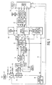
- FIG. 1 presents a block schematic diagram of a video apparatus which can accept various video input signals of either standard or high definition with a nominal scanning frequency of 1H or nominally 2H.
- the SD or 1H input signals are processed to enable display at a double frequency rate.
- Standard definition signals are input to video processor integrated circuit U1 11, for example Toshiba type TA1286NF, via a selector switch matrix SW 12 which allows user selection from various sources, for example, a demodulated RF or IF signal 13, an external Y/C component signal 16 comprising luminance and encoded subcarrier 14, NTSC encoded signals 15 or Y/Pr/Pb input 14 .
- the external composite NTSC signal is initially comb filtered to produce separated luminance and encoded subcarrier prior to the selector matrix switch 12 .
- the SD input 17 to video processor U1 11 is in the form of luminance and encoded subcarrier components known as YC.
- Video processor U1 11 includes a sync separator SS, and an NTSC decoder and matrix arrangement which decodes and forms color difference signals for example R-Y, and B-Y or Pr and Pb.
- the luminance or Y signal input is coupled via sync separator SS which provides separated (1H) sync pulses at pin 18 of IC U1 11 .
- the Y signal with sync pulses is output at pin 4 and coupled via an advantageous gated sync pulse stretcher, to an overlay switch or matrix switch integrated circuit U2, for example Toshiba type TA1287F.
- Video or program guide information is generated by a GemstarTM circuit module 19 and is coupled 20 as red, green and blue signals together with a fast switch signal, (FSW), for processing as an on screen display (OSD) by overlay switch IC U2 18, prior to up-conversion.
- FSW fast switch signal
- the switching or mixed superimposition of the GemstarTM OSD signals 20 is accomplished by IC U2 18, which in addition also provides a matrix which converts the GemStarTM originated RGB OSD signals 20 to luminance and color difference components, for example Y R-Y B-Y, Y Pr Pb, YUV or YIQ.
- the GemStar module 19 has its own RAM and supplies 1H program guide data either from RAM derived from VBI information or a canned demo program guide stored in ROM.
- the demo data gets loaded into RAM from the ROM to simulate live data.
- the demo data is erased from the RAM.
- overlay switch IC U2 18 The outputs from overlay switch IC U2 18 are coupled via Pr/Pb clamps 22, to a digital decoder, IC U3 23, for example Samsung type KS0127B.
- Integrated circuit U3 23 digitizes the luminance and coloring signals received from overlay switch U2 18 and forms a data stream 24 conforming to CCIR standard 656.
- the master source of horizontal 21 and vertical 25 sync signals is chosen to be sync signals extracted from the luminance signal input to digital decoder U3 23 .
- the digitized component signal bit stream (Bs) is coupled to a de-interlacer system comprising a de-interlacing integrated circuit U4 26, for example Genesis Micro type gmVLX1A-X, and a film mode controller IC U6 27, for example Genesis Micro type gmAFMC.
- Integrated circuit U6 27 is controlled by and communicates with chassis controller U8 38 via the I 2 C bus 28, however communication between IC U4 26 and IC U6 27 is via a separate data bus 29 .
- De-interlacing is initiated within IC U4 26 which examines the incoming component video data stream to determine the best method for constructing interpolated lines prior to storing each field in a 32 bit SGRAM memory IC U5 30, for example AMIC type A45L9332.
- Film mode controller IC, U6 27 detects the presence of video signals which originated from 24 Hz film by monitoring motion artifacts for the presence of a cyclical variation occurring at a 5 field rate. This 5 field repetition rate results from a so called 3:2 pull-down telecine process used to produce a nominal display rate of 60Hz by the cyclical duplication of individual fields.
- the interpolated signal can be assembled with temporally correct lines from a previous field.
- the resulting 2H scan rate digital video in the form of three 8 bit data streams (Y 31 , Pr 32 and Pb 33 ) are output from de-interlacing IC U4 26 and coupled for digital to analog conversion and analog signal processing prior to subsequent display.
- the D-to-A processing is performed by, for example, by U10 34, an Analog Devices ADV7123 IC.
- the analog output of this IC is then further processed by a back-end video processor 35 which produce RGB outputs 36 to be displayed on a display device 21 .
- a 2-H or high resolution source may be inputted to the present system via for example, the Y/Pr/Pb input 14 connected to the matrix switch. If the system is then put into the 2-H mode, this matrix switch 12 will cause the signal to be routed 37 to the video processor 35 to be processed directly, without the up conversion previously described.
- FIG. 2 shows a flow chart exemplifying the present invention.
- the routine is entered at step 200 .
- this feature may be set as default (i.e., on or off) either at the factory or by a user. If this feature is set to on 202 , the chassis controller will first determine 204 if a selection has been made to activate the guide demo. At step 205 , if this selection has been made, the controller will automatically switch the system to 1H mode and start to show the guide demo which has been previously stored in the system. The controller will then determine if the demo has finished or has been terminated by a user, at step 210 . If either of these is the case, then the controller will switch the system automatically to a high resolution or a high definition mode, as shown in step 215 . The routine is exited by 220 .
- a preferred embodiment is a high definition television monitor which includes a GemStar electronic program guide module 19 having a program guide demonstration burned into ROM which is designed to display a program guide having canned data to prospective customers upon pressing a program guide key on a remote control unit while the television monitor is in demo mode.
- the television monitor is programmed to automatically display a source of 2H signal, preferably from a 2H DVD player when the 1H program guide is not selected.
- the television monitor Upon selection of the 1H program guide, the television monitor switches to 1H mode until the prospective customer reselects a source of 2H signal such as the DVD player or until the program guide demo is completed, or until a predetermined time period has expired at which point the television monitor resumes 2H mode.
- the guide software preferably sends an end of demo signal to the television software which in turn switches the sources back to the 2H input.
- the demo can be of various types. For example, it can be a continuous demo which is activated using either the remote controller or front panel keys to select the appropriate menu item. Alternatively, it can be triggered by the presence of a hardware pin plugged into a port in the back of the television set which causes the demo to start automatically when the customer in the retail setting presses the electronic program guide key, i.e., the same program guide key as is used in a normal at home setting.
Landscapes
- Engineering & Computer Science (AREA)
- Multimedia (AREA)
- Signal Processing (AREA)
- Controls And Circuits For Display Device (AREA)
- Television Systems (AREA)
Abstract
Description
- This application claims the benefit of U.S. Provisional Application 60/316,246 filed August 31, 2001, in the names of the present inventors.
- The present invention generally relates to high definition television systems and methods, and particularly to high definition televisions which are capable of displaying an electronic program guide demonstration in low definition mode.
- Low definition, or standard definition, modes of television systems have a horizontal scanning frequency of 15.734 KHz (1H). High definition is defined as a scanning frequency of nominally 2.14H (2H) or about 33.6 KHz.
- It is a common practice in a retail setting to display a high-resolution source such as a source from a
progressive scan 2H DVD player on a TV/Monitor capable of displaying either the high-resolution source (2H) or the standard resolution source (1H), in order to impress potential customers with the capability of the television. One example of such a television capable of displaying such multiple sources is the RCA model CTC210, marketed by Thomson Multimedia, Inc., of Indianapolis, IN. The CTC 210 and similar television systems, however, contain in permanent memory a simulated interactive program guide that can only be displayed while the television is in the 1H mode. - The present inventors recognize that it is desirable to allow potential customers to run the guide demo since it is a significant feature. But since the program guide cannot be displayed in non-1H modes, there is a need for such televisions to automatically change to the 1-H mode when the guide demo is requested.
- The present invention relates to automatically returning the television mode to 2H so that it can display the high-resolution source.
- It is common for a customer to start the program guide demo then walk away, without manually ending the demo, thereby leaving the television in 1-H mode.
- It is an object of the present invention to overcome this problem in the art by automatically returning the television to 2-H mode after the program guide demo is completed, without any user intervention.
- Another object of the invention is to make the automatic return to 2-H mode an optional feature which can be turned on and off by a user or at the factory.
- These objects and others which will become apparent from the following disclosure and the accompanying drawings are achieved by the present invention which comprises a television system comprising
- means to display video from a first source in a low definition (1H) mode and to display video from a second source in a high definition (2H) mode;
- means to switch to 1H mode when the first source is selected; and means to automatically switch to 2H mode when the first source is deselected or inactive.
-
- In another aspect, the invention comprises a method of displaying a low definition (1H) program guide on a high definition television monitor comprising
- receiving a user selection to display a program guide;
- switching to a 1H mode; and
- upon completion of the program guide selection, automatically switching to a 2H mode.
-
- The preferred first source is an electronic program guide stored in memory, and the preferred second sources are external digital video disk (DVD) player, a gaming system, or a satellite box.
- The system is preferably programmed to automatically switch to 1H mode when the demonstration program guide is selected or is automatically started. The demonstration can be started with a remote controller when a customer in a retail setting presses a program guide key. The television set can include a hardware pin which, when plugged into a port on the back of the TV, can trigger the demonstration whenever a customer selects program guide with the controller or panel keys. A software program can automatically start the program guide demo at predetermined times or after elapse of a predetermined time in an alternative embodiment.
- The 1H video supplied by the first or other source can be upconverted to 2H using conventional circuitry adapted for that purpose.
-
- FIG. 1 is a simplified block schematic diagram of a video apparatus according to the invention.
- FIG. 2 represents a flow chart according to the present invention.
-
- FIG. 1 presents a block schematic diagram of a video apparatus which can accept various video input signals of either standard or high definition with a nominal scanning frequency of 1H or nominally 2H.
- The SD or 1H input signals are processed to enable display at a double frequency rate. Standard definition signals are input to video processor integrated
circuit U1 11, for example Toshiba type TA1286NF, via a selectorswitch matrix SW 12 which allows user selection from various sources, for example, a demodulated RF orIF signal 13, an external Y/C component signal 16 comprising luminance and encodedsubcarrier 14, NTSC encoded signals 15 or Y/Pr/Pb input 14. - The external composite NTSC signal is initially comb filtered to produce separated luminance and encoded subcarrier prior to the
selector matrix switch 12. Thus theSD input 17 tovideo processor U1 11 is in the form of luminance and encoded subcarrier components known as YC. Video processor U1 11 includes a sync separator SS, and an NTSC decoder and matrix arrangement which decodes and forms color difference signals for example R-Y, and B-Y or Pr and Pb. The luminance or Y signal input is coupled via sync separator SS which provides separated (1H) sync pulses atpin 18 ofIC U1 11. The Y signal with sync pulses is output at pin 4 and coupled via an advantageous gated sync pulse stretcher, to an overlay switch or matrix switch integrated circuit U2, for example Toshiba type TA1287F. - Video or program guide information is generated by a Gemstar
™ circuit module 19 and is coupled 20 as red, green and blue signals together with a fast switch signal, (FSW), for processing as an on screen display (OSD) by overlay switch IC U2 18, prior to up-conversion. The switching or mixed superimposition of the Gemstar™ OSD signals 20 is accomplished by IC U2 18, which in addition also provides a matrix which converts the GemStar™ originated RGB OSD signals 20 to luminance and color difference components, for example Y R-Y B-Y, Y Pr Pb, YUV or YIQ. The GemStarmodule 19 has its own RAM and supplies 1H program guide data either from RAM derived from VBI information or a canned demo program guide stored in ROM. In the case where the demonstration data is stored in ROM, when the demonstration is started, if there is no live data present in RAM, the demo data gets loaded into RAM from the ROM to simulate live data. When the demo is exited, the demo data is erased from the RAM. - The outputs from overlay switch IC U2 18 are coupled via Pr/
Pb clamps 22, to a digital decoder, ICU3 23, for example Samsung type KS0127B.Integrated circuit U3 23 digitizes the luminance and coloring signals received fromoverlay switch U2 18 and forms a data stream 24 conforming to CCIR standard 656. In this receiver monitor display system, the master source of horizontal 21 and vertical 25 sync signals is chosen to be sync signals extracted from the luminance signal input todigital decoder U3 23. - The digitized component signal bit stream (Bs) is coupled to a de-interlacer system comprising a de-interlacing integrated
circuit U4 26, for example Genesis Micro type gmVLX1A-X, and a film modecontroller IC U6 27, for example Genesis Micro type gmAFMC.Integrated circuit U6 27 is controlled by and communicates with chassis controller U8 38 via the I2C bus 28, however communication between IC U4 26 and IC U6 27 is via aseparate data bus 29. De-interlacing is initiated withinIC U4 26 which examines the incoming component video data stream to determine the best method for constructing interpolated lines prior to storing each field in a 32 bit SGRAMmemory IC U5 30, for example AMIC type A45L9332. If motion is not detected, the system repeats information from the previous field to provide a complete frame of non-moving video. However, if motion is detected, vertical/temporal filtering is applied using lines and fields around the interpolated line to provide an interpolated signal essentially free of motion artifacts. Film mode controller IC,U6 27 detects the presence of video signals which originated from 24 Hz film by monitoring motion artifacts for the presence of a cyclical variation occurring at a 5 field rate. This 5 field repetition rate results from a so called 3:2 pull-down telecine process used to produce a nominal display rate of 60Hz by the cyclical duplication of individual fields. Thus, having detected film original material the interpolated signal can be assembled with temporally correct lines from a previous field. - The resulting 2H scan rate digital video, in the form of three 8 bit data streams (
Y 31,Pr 32 and Pb 33) are output from de-interlacingIC U4 26 and coupled for digital to analog conversion and analog signal processing prior to subsequent display. The D-to-A processing is performed by, for example, byU10 34, an Analog Devices ADV7123 IC. The analog output of this IC is then further processed by a back-end video processor 35 which produceRGB outputs 36 to be displayed on adisplay device 21. - A 2-H or high resolution source may be inputted to the present system via for example, the Y/Pr/
Pb input 14 connected to the matrix switch. If the system is then put into the 2-H mode, thismatrix switch 12 will cause the signal to be routed 37 to the video processor 35 to be processed directly, without the up conversion previously described. - FIG. 2 shows a flow chart exemplifying the present invention. The routine is entered at
step 200. As shown inStep 201, this feature may be set as default (i.e., on or off) either at the factory or by a user. If this feature is set to on 202, the chassis controller will first determine 204 if a selection has been made to activate the guide demo. Atstep 205, if this selection has been made, the controller will automatically switch the system to 1H mode and start to show the guide demo which has been previously stored in the system. The controller will then determine if the demo has finished or has been terminated by a user, atstep 210. If either of these is the case, then the controller will switch the system automatically to a high resolution or a high definition mode, as shown instep 215. The routine is exited by 220. - A preferred embodiment is a high definition television monitor which includes a GemStar electronic
program guide module 19 having a program guide demonstration burned into ROM which is designed to display a program guide having canned data to prospective customers upon pressing a program guide key on a remote control unit while the television monitor is in demo mode. The television monitor is programmed to automatically display a source of 2H signal, preferably from a 2H DVD player when the 1H program guide is not selected. - Upon selection of the 1H program guide, the television monitor switches to 1H mode until the prospective customer reselects a source of 2H signal such as the DVD player or until the program guide demo is completed, or until a predetermined time period has expired at which point the television monitor resumes 2H mode. The guide software preferably sends an end of demo signal to the television software which in turn switches the sources back to the 2H input.
- The demo can be of various types. For example, it can be a continuous demo which is activated using either the remote controller or front panel keys to select the appropriate menu item. Alternatively, it can be triggered by the presence of a hardware pin plugged into a port in the back of the television set which causes the demo to start automatically when the customer in the retail setting presses the electronic program guide key, i.e., the same program guide key as is used in a normal at home setting.
Claims (15)
- A television system comprisingmeans to display video from a first source in a low definition (1H) mode and to display video from a second source in a high definition (2H) mode;means to switch to 1H mode when the first source is selected; andmeans to automatically switch to 2H mode when the first source is deselected or inactive.
- The television system of claim 1 wherein the first source is an electronic program guide demonstration stored in memory.
- The television system of claim 1 wherein the second source is an external digital video disk (DVD) player, a gaming system, or a satellite box.
- The television system of claim 1 wherein the means to switch to 1H mode comprises means to select a program guide demonstration.
- The television system of claim 1 wherein the means to switch to 1H mode comprises a remote controller with a program guide demonstration switch, a key or combination of keys on a front panel, or a software program which automatically starts the program guide demonstration after a predetermined period of time has passed after a previous demonstration.
- The television system of claim 1 wherein the means to automatically switch to 2H mode is a controller which is programmed to switch to 2H if the first source is finished or has exceeded a predetermined timeout period.
- The television system of claim 1 comprising means to upconvert 1H video supplied by the first source to 2H.
- A method of displaying a low definition (1H) program guide on a high definition television monitor comprisingreceiving a user selection to display a program guide;switching to a 1H mode; andupon completion of the program guide selection, automatically switching to a 2H mode.
- The method of claim 8 wherein the program guide is a user selectable demonstration which is digitally encoded and stored.
- The method of claim 8 wherein video from a digital video disk (DVD) player, a satellite box, or a gaming system is processed and displayed when the television monitor is switched to 2H mode.
- The method of claim 8 comprising switching to 2H mode when the program guide is unselected by the user or when a predetermined time elapses or predetermined period of inactivity occurs.
- The method of claim 8 wherein the source of 2H is a high definition television tuner.
- The method of claim 8 wherein the program guide is a user selectable demonstration which is digitally encoded and stored and does not comprise live data obtained via a video blanking interval (VBI).
- The method of claim 1 wherein a 1H video signal is upconverted to 2H and displayed in high resolution.
- The method of claim 14 wherein the 1H program guide is overlayed on the 1H video signal and then upconverted to 2H.
Applications Claiming Priority (2)
| Application Number | Priority Date | Filing Date | Title |
|---|---|---|---|
| US31624601P | 2001-08-31 | 2001-08-31 | |
| US316246P | 2001-08-31 |
Publications (2)
| Publication Number | Publication Date |
|---|---|
| EP1289286A2 true EP1289286A2 (en) | 2003-03-05 |
| EP1289286A3 EP1289286A3 (en) | 2003-05-02 |
Family
ID=23228206
Family Applications (1)
| Application Number | Title | Priority Date | Filing Date |
|---|---|---|---|
| EP02292006A Withdrawn EP1289286A3 (en) | 2001-08-31 | 2002-08-09 | Automatic return to a high-definition mode after guide demonstration |
Country Status (7)
| Country | Link |
|---|---|
| US (1) | US8743285B2 (en) |
| EP (1) | EP1289286A3 (en) |
| JP (1) | JP4122191B2 (en) |
| KR (1) | KR100913930B1 (en) |
| CN (1) | CN1265632C (en) |
| MX (1) | MXPA02008341A (en) |
| MY (1) | MY127717A (en) |
Families Citing this family (7)
| Publication number | Priority date | Publication date | Assignee | Title |
|---|---|---|---|---|
| KR100951879B1 (en) * | 2006-02-23 | 2010-04-12 | 삼성전자주식회사 | Screen adjustment method and image processing device performing the same |
| WO2007116351A2 (en) * | 2006-04-11 | 2007-10-18 | Koninklijke Philips Electronics N.V. | Method and apparatus for setting the state of operation of an appliance |
| US20090153736A1 (en) * | 2007-12-17 | 2009-06-18 | Peter Mortensen | Embedded video demo mode for television |
| US20090212904A1 (en) * | 2008-02-25 | 2009-08-27 | Sanyo Electric Co., Ltd. | Electronic device provided with theft prevention function, and method for preventing theft of electronic devices |
| CN101277403B (en) * | 2008-03-31 | 2010-09-01 | 深圳创维数字技术股份有限公司 | Circuit and method for switching video signal of digital television receiver |
| US20110090401A1 (en) * | 2009-10-20 | 2011-04-21 | Sony Corporation | System and Method for Triggering a Demonstration Mode of a Display Device |
| CN102413293B (en) * | 2010-09-21 | 2013-11-20 | 深圳Tcl新技术有限公司 | System and method for automatically linking high-definition programs |
Citations (2)
| Publication number | Priority date | Publication date | Assignee | Title |
|---|---|---|---|---|
| US5557337A (en) * | 1994-02-18 | 1996-09-17 | Hitachi America, Ltd. | Automatic television signal detector to differentiate NTSC signals from HDJV/AJV signals |
| US6108044A (en) * | 1997-04-10 | 2000-08-22 | Samsung Electronics Co., Ltd. | Receiver for receiving both HDTV and NTSC and method for selecting received signals |
Family Cites Families (21)
| Publication number | Priority date | Publication date | Assignee | Title |
|---|---|---|---|---|
| US4386377A (en) * | 1981-04-10 | 1983-05-31 | Rca Corporation | TV Interface RF modulation circuitry |
| JP2842913B2 (en) | 1990-01-24 | 1999-01-06 | 株式会社日立製作所 | Wide television signal processing circuit |
| FR2707130A1 (en) * | 1993-06-30 | 1995-01-06 | Philips Laboratoire Electroniq | System for receiving and decoding digital signals according to two levels of image definition. |
| US6418556B1 (en) * | 1993-09-09 | 2002-07-09 | United Video Properties, Inc. | Electronic television program guide schedule system and method |
| US5461427A (en) | 1994-06-28 | 1995-10-24 | Thomson Consumer Electronics, Inc. | Television receiver having the capability to associate any HDTV and any NTSC channel |
| US5530484A (en) | 1995-05-19 | 1996-06-25 | Thomson Multimedia S.A | Image scanning format converter suitable for a high definition television system |
| US5748254A (en) * | 1995-07-24 | 1998-05-05 | Coach Master International Corporation | Systems with a remote control in which information can be retrieved from an encoded, laser readable disc |
| US5764304A (en) * | 1995-12-08 | 1998-06-09 | Coach Master International Corporation | Operation of information/entertainment centers |
| JP3431417B2 (en) * | 1996-09-04 | 2003-07-28 | 株式会社ケンウッド | Digital satellite broadcast receiver |
| JP3218192B2 (en) | 1996-10-14 | 2001-10-15 | 三菱レイヨン株式会社 | Flame retardant resin composition |
| JPH10285485A (en) * | 1997-04-03 | 1998-10-23 | Matsushita Electric Ind Co Ltd | Television broadcast receiver |
| KR100252939B1 (en) * | 1997-07-18 | 2000-04-15 | 구자홍 | A program guide offerer of analog and digital broadcasting system and a method for offer using the same |
| KR100224861B1 (en) * | 1997-08-01 | 1999-10-15 | 윤종용 | A received signal discrimination circuit and method |
| JPH1169251A (en) | 1997-08-21 | 1999-03-09 | Hitachi Ltd | Digital broadcasting receiver |
| JP3882295B2 (en) | 1997-11-10 | 2007-02-14 | 株式会社日立製作所 | Digital broadcast receiving apparatus and video signal muting method |
| JP4066212B2 (en) | 1998-06-10 | 2008-03-26 | 船井電機株式会社 | Digital broadcast receiver and control method thereof |
| US6504826B1 (en) * | 1998-08-24 | 2003-01-07 | Hitachi, Ltd. | Digital broadcasting receiver |
| JP2000138877A (en) | 1998-08-24 | 2000-05-16 | Hitachi Ltd | Digital broadcast transmitting device and receiving device |
| JP2000152114A (en) * | 1998-11-11 | 2000-05-30 | Toshiba Corp | Mottle broadcast content display device and display method thereof |
| JP2003518343A (en) | 1999-05-13 | 2003-06-03 | インデックス システムズ インコーポレイテッド | Download system for consumer electronic devices |
| JP3625713B2 (en) | 1999-10-04 | 2005-03-02 | 三洋電機株式会社 | Digital broadcast receiver |
-
2002
- 2002-07-24 US US10/202,324 patent/US8743285B2/en not_active Expired - Lifetime
- 2002-08-09 EP EP02292006A patent/EP1289286A3/en not_active Withdrawn
- 2002-08-20 JP JP2002239835A patent/JP4122191B2/en not_active Expired - Lifetime
- 2002-08-27 MX MXPA02008341A patent/MXPA02008341A/en active IP Right Grant
- 2002-08-27 MY MYPI20023173A patent/MY127717A/en unknown
- 2002-08-30 CN CNB021414920A patent/CN1265632C/en not_active Expired - Lifetime
- 2002-08-30 KR KR1020020051833A patent/KR100913930B1/en not_active Expired - Lifetime
Patent Citations (2)
| Publication number | Priority date | Publication date | Assignee | Title |
|---|---|---|---|---|
| US5557337A (en) * | 1994-02-18 | 1996-09-17 | Hitachi America, Ltd. | Automatic television signal detector to differentiate NTSC signals from HDJV/AJV signals |
| US6108044A (en) * | 1997-04-10 | 2000-08-22 | Samsung Electronics Co., Ltd. | Receiver for receiving both HDTV and NTSC and method for selecting received signals |
Also Published As
| Publication number | Publication date |
|---|---|
| MY127717A (en) | 2006-12-29 |
| JP2003116075A (en) | 2003-04-18 |
| CN1407800A (en) | 2003-04-02 |
| KR20030019237A (en) | 2003-03-06 |
| CN1265632C (en) | 2006-07-19 |
| US20030043296A1 (en) | 2003-03-06 |
| US8743285B2 (en) | 2014-06-03 |
| KR100913930B1 (en) | 2009-08-27 |
| EP1289286A3 (en) | 2003-05-02 |
| JP4122191B2 (en) | 2008-07-23 |
| MXPA02008341A (en) | 2005-08-26 |
Similar Documents
| Publication | Publication Date | Title |
|---|---|---|
| US6580461B2 (en) | Line-quadrupler in home theater uses line-doubler of AV-part and scaler in graphics controller of PC-part | |
| US5844623A (en) | Television with integrated receiver decoder | |
| US5023721A (en) | TV of internal PiP type for receiving the character multibroadcasting | |
| CA2312562C (en) | Image signal conversion equipment | |
| JP5056211B2 (en) | Video signal conversion device, video signal conversion method, and video display device | |
| US8743285B2 (en) | Automatic return to a high-definition mode after guide demonstration | |
| JP3497709B2 (en) | Simultaneous display of television image and personal computer image | |
| US20060146189A1 (en) | Processing signals for a color sequential display | |
| USRE37501E1 (en) | Apparatus and method for displaying caption broadcast and teletext on the screen of a double-wide television | |
| US7352406B2 (en) | Signal acquisition following transient signal interruption | |
| JPH1079899A (en) | Television receiver | |
| US8049818B2 (en) | Video processing apparatus and method | |
| EP1294182B1 (en) | Signal acquisition following transient signal interruption | |
| KR20020054933A (en) | Image processing apparatus capable of changing active size and method for changing the active size thereof | |
| JP3147726B2 (en) | Video signal processing device | |
| KR960009093Y1 (en) | Pictur in Pictur TV receiver | |
| JPH04302594A (en) | MUSE-NTSC converter | |
| JP2000175120A (en) | Video signal switch circuit/method | |
| JPH07312728A (en) | Television receiver | |
| JPH10191200A (en) | Liquid crystal display | |
| JPH07303191A (en) | Video signal processor | |
| JPH0564099A (en) | Television receiver with built-in telop display circuit | |
| JP2001054107A (en) | Multi-screen display controller | |
| JPH06141254A (en) | Monitor device | |
| JP2002281452A (en) | Magnetic recording / reproducing device |
Legal Events
| Date | Code | Title | Description |
|---|---|---|---|
| PUAI | Public reference made under article 153(3) epc to a published international application that has entered the european phase |
Free format text: ORIGINAL CODE: 0009012 |
|
| AK | Designated contracting states |
Kind code of ref document: A2 Designated state(s): AT BE BG CH CY CZ DE DK EE ES FI FR GB GR IE IT LI LU MC NL PT SE SK TR Designated state(s): AT BE BG CH CY CZ DE DK EE ES FI FR GB GR IE IT LI LU MC NL PT SE SK TR |
|
| AX | Request for extension of the european patent |
Extension state: AL LT LV MK RO SI |
|
| PUAL | Search report despatched |
Free format text: ORIGINAL CODE: 0009013 |
|
| AK | Designated contracting states |
Designated state(s): AT BE BG CH CY CZ DE DK EE ES FI FR GB GR IE IT LI LU MC NL PT SE SK TR |
|
| AX | Request for extension of the european patent |
Extension state: AL LT LV MK RO SI |
|
| 17P | Request for examination filed |
Effective date: 20031011 |
|
| AKX | Designation fees paid |
Designated state(s): DE GB |
|
| RAP1 | Party data changed (applicant data changed or rights of an application transferred) |
Owner name: THOMSON LICENSING |
|
| 17Q | First examination report despatched |
Effective date: 20090403 |
|
| RAP1 | Party data changed (applicant data changed or rights of an application transferred) |
Owner name: THOMSON LICENSING |
|
| STAA | Information on the status of an ep patent application or granted ep patent |
Free format text: STATUS: THE APPLICATION HAS BEEN WITHDRAWN |
|
| 18W | Application withdrawn |
Effective date: 20101109 |