EP1289136A2 - Surface acoustic wave filter and communication apparatus. - Google Patents
Surface acoustic wave filter and communication apparatus. Download PDFInfo
- Publication number
- EP1289136A2 EP1289136A2 EP02255590A EP02255590A EP1289136A2 EP 1289136 A2 EP1289136 A2 EP 1289136A2 EP 02255590 A EP02255590 A EP 02255590A EP 02255590 A EP02255590 A EP 02255590A EP 1289136 A2 EP1289136 A2 EP 1289136A2
- Authority
- EP
- European Patent Office
- Prior art keywords
- ground
- interdigital
- electrode finger
- piezoelectric substrate
- filter
- Prior art date
- Legal status (The legal status is an assumption and is not a legal conclusion. Google has not performed a legal analysis and makes no representation as to the accuracy of the status listed.)
- Withdrawn
Links
Images


Classifications
-
- H—ELECTRICITY
- H03—ELECTRONIC CIRCUITRY
- H03H—IMPEDANCE NETWORKS, e.g. RESONANT CIRCUITS; RESONATORS
- H03H9/00—Networks comprising electromechanical or electro-acoustic devices; Electromechanical resonators
- H03H9/46—Filters
- H03H9/64—Filters using surface acoustic waves
-
- H—ELECTRICITY
- H03—ELECTRONIC CIRCUITRY
- H03H—IMPEDANCE NETWORKS, e.g. RESONANT CIRCUITS; RESONATORS
- H03H9/00—Networks comprising electromechanical or electro-acoustic devices; Electromechanical resonators
- H03H9/0023—Balance-unbalance or balance-balance networks
- H03H9/0028—Balance-unbalance or balance-balance networks using surface acoustic wave devices
- H03H9/0033—Balance-unbalance or balance-balance networks using surface acoustic wave devices having one acoustic track only
- H03H9/0042—Balance-unbalance or balance-balance networks using surface acoustic wave devices having one acoustic track only the balanced terminals being on opposite sides of the track
-
- H—ELECTRICITY
- H03—ELECTRONIC CIRCUITRY
- H03H—IMPEDANCE NETWORKS, e.g. RESONANT CIRCUITS; RESONATORS
- H03H9/00—Networks comprising electromechanical or electro-acoustic devices; Electromechanical resonators
- H03H9/0023—Balance-unbalance or balance-balance networks
- H03H9/0028—Balance-unbalance or balance-balance networks using surface acoustic wave devices
- H03H9/0047—Balance-unbalance or balance-balance networks using surface acoustic wave devices having two acoustic tracks
- H03H9/0052—Balance-unbalance or balance-balance networks using surface acoustic wave devices having two acoustic tracks being electrically cascaded
- H03H9/0061—Balance-unbalance or balance-balance networks using surface acoustic wave devices having two acoustic tracks being electrically cascaded the balanced terminals being on opposite sides of the tracks
-
- H—ELECTRICITY
- H03—ELECTRONIC CIRCUITRY
- H03H—IMPEDANCE NETWORKS, e.g. RESONANT CIRCUITS; RESONATORS
- H03H9/00—Networks comprising electromechanical or electro-acoustic devices; Electromechanical resonators
- H03H9/02—Details
- H03H9/125—Driving means, e.g. electrodes, coils
- H03H9/145—Driving means, e.g. electrodes, coils for networks using surface acoustic waves
- H03H9/14544—Transducers of particular shape or position
- H03H9/14576—Transducers whereby only the last fingers have different characteristics with respect to the other fingers, e.g. different shape, thickness or material, split finger
- H03H9/14582—Transducers whereby only the last fingers have different characteristics with respect to the other fingers, e.g. different shape, thickness or material, split finger the last fingers having a different pitch
-
- H—ELECTRICITY
- H01—ELECTRIC ELEMENTS
- H01L—SEMICONDUCTOR DEVICES NOT COVERED BY CLASS H10
- H01L2224/00—Indexing scheme for arrangements for connecting or disconnecting semiconductor or solid-state bodies and methods related thereto as covered by H01L24/00
- H01L2224/01—Means for bonding being attached to, or being formed on, the surface to be connected, e.g. chip-to-package, die-attach, "first-level" interconnects; Manufacturing methods related thereto
- H01L2224/02—Bonding areas; Manufacturing methods related thereto
- H01L2224/04—Structure, shape, material or disposition of the bonding areas prior to the connecting process
- H01L2224/06—Structure, shape, material or disposition of the bonding areas prior to the connecting process of a plurality of bonding areas
- H01L2224/061—Disposition
- H01L2224/0612—Layout
-
- H—ELECTRICITY
- H01—ELECTRIC ELEMENTS
- H01L—SEMICONDUCTOR DEVICES NOT COVERED BY CLASS H10
- H01L2224/00—Indexing scheme for arrangements for connecting or disconnecting semiconductor or solid-state bodies and methods related thereto as covered by H01L24/00
- H01L2224/01—Means for bonding being attached to, or being formed on, the surface to be connected, e.g. chip-to-package, die-attach, "first-level" interconnects; Manufacturing methods related thereto
- H01L2224/10—Bump connectors; Manufacturing methods related thereto
- H01L2224/15—Structure, shape, material or disposition of the bump connectors after the connecting process
- H01L2224/16—Structure, shape, material or disposition of the bump connectors after the connecting process of an individual bump connector
- H01L2224/161—Disposition
- H01L2224/16151—Disposition the bump connector connecting between a semiconductor or solid-state body and an item not being a semiconductor or solid-state body, e.g. chip-to-substrate, chip-to-passive
- H01L2224/16221—Disposition the bump connector connecting between a semiconductor or solid-state body and an item not being a semiconductor or solid-state body, e.g. chip-to-substrate, chip-to-passive the body and the item being stacked
- H01L2224/16225—Disposition the bump connector connecting between a semiconductor or solid-state body and an item not being a semiconductor or solid-state body, e.g. chip-to-substrate, chip-to-passive the body and the item being stacked the item being non-metallic, e.g. insulating substrate with or without metallisation
-
- H—ELECTRICITY
- H01—ELECTRIC ELEMENTS
- H01L—SEMICONDUCTOR DEVICES NOT COVERED BY CLASS H10
- H01L2224/00—Indexing scheme for arrangements for connecting or disconnecting semiconductor or solid-state bodies and methods related thereto as covered by H01L24/00
- H01L2224/01—Means for bonding being attached to, or being formed on, the surface to be connected, e.g. chip-to-package, die-attach, "first-level" interconnects; Manufacturing methods related thereto
- H01L2224/42—Wire connectors; Manufacturing methods related thereto
- H01L2224/47—Structure, shape, material or disposition of the wire connectors after the connecting process
- H01L2224/49—Structure, shape, material or disposition of the wire connectors after the connecting process of a plurality of wire connectors
- H01L2224/491—Disposition
- H01L2224/4911—Disposition the connectors being bonded to at least one common bonding area, e.g. daisy chain
- H01L2224/49113—Disposition the connectors being bonded to at least one common bonding area, e.g. daisy chain the connectors connecting different bonding areas on the semiconductor or solid-state body to a common bonding area outside the body, e.g. converging wires
-
- H—ELECTRICITY
- H01—ELECTRIC ELEMENTS
- H01L—SEMICONDUCTOR DEVICES NOT COVERED BY CLASS H10
- H01L2924/00—Indexing scheme for arrangements or methods for connecting or disconnecting semiconductor or solid-state bodies as covered by H01L24/00
- H01L2924/15—Details of package parts other than the semiconductor or other solid state devices to be connected
- H01L2924/161—Cap
- H01L2924/1615—Shape
- H01L2924/16195—Flat cap [not enclosing an internal cavity]
Definitions
- the present invention relates to a surface acoustic wave filter having filtering characteristics and a balance-to-unbalance conversion function, and to a communication apparatus using the surface acoustic wave filter.
- SAW surface acoustic wave
- balun is thus required for preventing the unbalanced current in order to match the balanced line to the unbalanced line.
- a comb-like electrode (also called an interdigital transducer, hereinafter referred to as an "IDT") 102 is formed on a piezoelectric substrate 100.
- IDTs 101 and 103 are positioned on the left and right sides of the IDT 102, respectively, in the surface acoustic wave (SAW) propagation direction.
- SAW surface acoustic wave
- Reflectors 104 and 105 for reflecting a surface acoustic wave in order to improve the conversion efficiency are further arranged in the SAW filter in such a manner that they sandwich the IDTs 101, 102, and 103 therebetween from the left and right.
- Balanced signal terminals 106 and 107 are connected to sets of electrode fingers of the centre IDT 102, respectively.
- An unbalanced signal terminal 108 is connected to one set of electrode fingers of each of the IDTs 101 and 103.
- the SAW filter of this type is called a three-IDT longitudinally coupled resonator SAW filter having a balance-to-unbalance conversion function by performing conversion between the IDTs 101, 102, and 103 using a surface acoustic wave.
- the extent how the balanced signal terminals 106 and 107 have equal amplitude characteristics and the extent how the balanced signal terminals 106 and 107 are 180° out of phase are referred to as "amplitude balance” and "phase balance", respectively.
- S21 denotes the transfer coefficient from the first port to the second port
- S31 denotes the transfer coefficient from the first port to the third port, and ⁇ indicates an absolute value.
- the amplitude balance and the phase balance are 0 dB and 0 degree, respectively, in the pass band of a SAW filter.
- the SAW filter in the related art shown in Fig. 11 has a problem in that balance between the balanced signal terminals 106 and 107 is reduced.
- a surface acoustic wave filter embodying the invention has a balance-to-unbalance conversion function and high balance between balanced signal terminals.
- a communication apparatus using the SAW filter may exhibit high transmission characteristics.
- a surface acoustic wave filter comprising: a piezoelectric substrate; a filter unit provided on the piezoelectric substrate, said filter unit having an odd number of three or more interdigital transducers including at least two end transducers and a centre transducer, the transducers being arranged along a surface acoustic wave propagation direction, each interdigital transducer having a pair of electrode finger sets; balanced signal terminals connected to the pair of electrode finger sets of the centre interdigital transducer; and an unbalanced signal terminal connected to one electrode finger set of each end interdigital transducers, the end interdigital transducers being different from the centre interdigital transducer, and being located on ends of the filter unit, the other electrode finger set of each end interdigital transducers being connected to a ground, wherein the ground for at least one of the end interdigital transducers is electrically isolated on the piezoelectric substrate from the ground for the other end interdigital transducer.
- the balanced signal terminals are connected to the pair of electrode finger sets of the centre IDT positioned at the centre of the IDTs, and the unbalanced signal terminal is connected to one electrode finger set of each of at least two end IDTs different from the centre IDT of the IDTs, thereby implementing a balance-to-unbalance conversion function.
- the ground for at least one end IDT of the end IDTs is electrically isolated on the piezoelectric substrate from the ground for the other end IDT, thereby making it possible to improve balance between the balanced signal terminals.
- a signal line which connects the unbalanced signal terminal to the end IDTs may be provided so as to surround one of the balanced signal terminals, and a ground line may be provided between the signal line and the balanced signal terminal surrounded by the signal line. This allows the bridge capacitance inserted between the signal line and the balanced signal terminal to be reduced by the ground line, thereby making it possible to improve balance between the balanced signal terminals.
- the invention also provides a surface acoustic wave filter comprising: a piezoelectric substrate; a plurality of filter units provided on the piezoelectric substrate, each filter unit having an odd number of three or more interdigital transducers including a first and a second transducer, the transducers arranged along a surface acoustic wave propagation direction, each interdigital transducer having a pair of electrode finger sets; balanced signal terminals being connected to the pair of electrode finger sets of the first centre interdigital transducer located at the centre of a first filter unit of the plurality of filter units; and an unbalanced signal terminal connected to one electrode finger set of the second centre interdigital transducer located at the centre of a second filter unit different from the first filter unit of the plurality of filter units, one electrode finger set of one or more end interdigital transducers different from the first and second centre interdigital transducers in the plurality of filter units being connected to a ground, said end interdigital transducers being located on ends of the first and second
- a piezoelectric substrate a plurality of filter units provided on the piezoelectric substrate, each unit having an odd number of at least three IDTs along a SAW propagation direction, each IDT having a pair of electrode finger sets.
- Balanced signal terminals are connected to the pair of electrode finger sets of a first centre IDT which is located at the centre of a first filter unit in the plurality of filter units, and an unbalanced signal terminal is connected to one electrode finger set of a second centre IDT which is located at the centre of a second filter unit different from the first filter unit in the plurality of filter units.
- One electrode finger set of each of end IDTs different from the first and second centre IDTs in the plurality of filter units is connected to a ground, and the end interdigital transducers being located on ends of the first and second filter units.
- the ground for at least one of the end IDTs is electrically isolated on the piezoelectric substrate from the ground for the other end IDT.
- the plurality of filter units can increase the out-of-passband attenuation, and can improve filtering characteristics.
- the balanced signal terminals are connected to the pair of electrode finger sets of the first centre IDT, and the unbalanced signal terminal is connected to one electrode finger set of the second centre IDT, thereby implementing a balance-to-unbalance conversion function.
- the ground for at least one end IDT of the end IDTs is electrically isolated on the piezoelectric substrate from the ground for the other end IDT, thereby improving balance between the balanced signal terminals.
- a package which receives the piezoelectric substrate may include a plurality of separate bonding pads for ground terminals.
- the grounds for the end IDTs that sandwich the centre IDT therebetween are connected to the different bonding pads so as to be electrically isolated from each other. With this configuration, the grounds for the end IDTs are separated, again, on the package, thereby making it possible to further improve balance between the balanced signal terminals.
- the IDT connected to the balanced signal terminals has an even number of electrode fingers in total. This enables the number of electrode fingers connected to one balanced signal terminal to be equal to the number of electrode fingers connected to the other balanced signal terminals, thereby further improving balance between the balanced signal terminals.
- At least one SAW resonator is connected at least in series or in parallel to the filter unit. This configuration can increase the out-of-passband attenuation, and can improve filtering characteristics.
- a communication apparatus includes the SAW filter according to any of the above-described configurations.
- the communication apparatus can improve transmission characteristics.
- a SAW filter according to an embodiment of the present invention is now described with reference to Figs. 1 to 10.
- the present invention is discussed in the context of a PCS (personal communication system) reception filter.
- a longitudinally coupled resonator SAW filter unit 202, and SAW resonators 203 and 204 connected in series to the SAW filter unit 202 are each formed of an aluminum (Al) electrode (foil) produced by a technique such as photolithography.
- the piezoelectric substrate 201 may be a 40 ⁇ 5° Y-cut X-propagating LiTaO 3 substrate.
- the SAW filter further includes a package 205 which receives, on the inner surface thereof, the piezoelectric substrate 201 carrying the SAW filter unit 202 and the like.
- the package 205 is a rectangular insulator plate made of alumina or the like.
- substantially rectangular thin metallic bonding pads 221, 223, and 225 for ground terminals are formed on the inner surface of the package 205 that is the same as the surface on which the piezoelectric substrate 201 rests.
- the bonding pads 221, 223, and 225 are adjacent to the piezoelectric substrate 201.
- a substantially rectangular thin metallic bonding pad 222 for an unbalanced signal input is further formed on this inner surface of the package 205 between the bonding pads 221 and 223 along the periphery of the inner surface.
- substantially rectangular thin metallic bonding pads 224 and 226 for outputs of balanced signal terminals are also formed in such a manner that they sandwich the bonding pad 225 therebetween.
- the SAW filter unit 202 includes a centre IDT 207, and IDTs (end IDTs) 206 and 208, which sandwich the IDT 207 therebetween from both sides in the SAW propagation direction.
- the SAW filter unit 202 further includes reflectors 209 and 210 positioned beside the IDTs 206 and 208, respectively.
- the IDTs 206, 207, and 208 each have two electrode finger portions each including a strip base portion (bus bar) and a plurality of strip electrode fingers extending in parallel to each other and extending orthogonally from one side of the base portion.
- the electrode finger portions are configured so that the electrode fingers of one electrode finger portion are interleaved with the electrode fingers of the other electrode finger portion such that the sides thereof face each other.
- any of the IDTs 206, 207, and 208 if a potential difference occurs due to electrical signals input to the two electrode finger portions via the base portions (bus bars), a surface acoustic wave is produced at that portion on a surface of the piezoelectric substrate 201.
- the surface acoustic wave then propagates across the surface of the piezoelectric substrate 201 in a bi-directional manner in the width direction of the electrode fingers, i.e., in the direction orthogonal to the length of the electrode fingers.
- the potential difference produced on the surface of the piezoelectric substrate 201 by the propagating surface acoustic wave is detected by the electrode fingers, and is converted into an output electrical signal, which is then output.
- the signal conversion characteristic or the pass band can be determined by setting the length and width of each electrode finger, the pitch between adjacent electrode fingers, and the interdigital length which means the length by which the interleaved electrode fingers face each other.
- the reflectors 209 and 210 reflect the propagating surface acoustic wave.
- the pitch between some electrode fingers (narrower-pitch electrode fingers) near the portion (indicated by a portion 211) where the IDTs 206 and 207 face each other is smaller than the pitch between the other electrode fingers of the IDTs 206 and 207.
- the pitch between some electrode fingers (narrower-pitch electrode fingers) near the portion (indicated by a portion 212) where the IDTs 207 and 208 face each other is narrower than the pitch between the other electrode fingers of the IDTs 207 and 208.
- the narrower-pitch electrode fingers allow the insertion loss to be reduced. For simplicity of illustration, the number of electrode fingers shown in Fig. 1 is less than actually provided.
- balanced signal terminals 214 and 215 are connected to the electrode finger portions of the IDT 207.
- an unbalanced signal terminal 213 is electrically connected to one electrode finger portion in each of the IDTs 206 and 208 through the SAW resonators 203 and 204 via a signal line 219.
- the signal line 219 is substantially C-shaped so as to surround the balanced signal terminal 214.
- a substantially C-shaped ground line 220 is inserted on the piezoelectric substrate 201 so as to isolate the signal line 219 and the balanced signal terminal 214 from each other.
- the ground line 220 allows the bridge capacitance between the signal line 219 and the balanced signal terminal 214 to be reduced, thereby improving balance between the balanced signal terminals 214 and 215.
- the signal line 219 and the ground line 220 are each formed of an aluminum (Al) electrode (foil) produced by a technique such as photolithography.
- the ground terminal 216 is electrically connected to the other electrode finger portion of the IDT 206.
- the ground terminal 217 is located on the ground line 220, and is electrically connected to the ground line 220.
- the ground terminal 218 is electrically connected to the other electrode finger portion of the IDT 208.
- a feature of the present embodiment is that the ground terminal 216 for the IDT 206 is electrically isolated from the ground terminal 218 for the IDT 208 on the piezoelectric substrate 201.
- the SAW filter unit 202 formed on the piezoelectric substrate 201 is electrically connected to the package 205 by a wire bonding method.
- the unbalanced signal terminal 213 is electrically connected to the bonding pad 222 of the package 205 via a bonding wire 227.
- the balanced signal terminal 214 is electrically connected to the bonding pad 224 via a bonding wire 228.
- the balanced signal terminal 215 is electrically connected to the bonding pad 226 via a bonding wire 229.
- the ground terminal 216 is electrically connected to the bonding pad 223 via a bonding wire 230.
- the ground terminals 217 and 218 are electrically connected to the bonding pad 225 via bonding wires 231 and 232, respectively.
- ground terminals 216 and 218 are electrically connected to the different bonding pads 223 and 225, respectively, while the bonding pads 223 and 225 are electrically isolated from each other in the package 205.
- the specific design of the longitudinally coupled resonator SAW filter unit 202 is as follows:
- the specific design of the SAW resonator 203 is as follows:
- the specific design of the SAW resonator 204 is as follows:
- Figs. 2 and 3 are graphs showing the amplitude balance and the phase balance between the balanced signal terminals 214 and 215, respectively, in the frequency characteristic of the SAW filter according to the present embodiment.
- Figs. 2 and 3 are graphs showing the amplitude balance and the phase balance between the balanced signal terminals 214 and 215, respectively, in the frequency characteristic of the SAW filter according to the present embodiment.
- the amplitude balance and the phase balance of a SAW filter as a comparative example are also shown in Figs. 2 and 3, respectively.
- the SAW filter in the comparative example is the same as the SAW filter shown in Fig. 1, except that the ground terminals 216 and 218 are combined into a single ground terminal.
- the frequency of the pass band of a PCS reception filter ranges from 1930 MHz to 1990 MHz.
- the maximum amplitude balance in this frequency range is 2.4 dB for the comparative example, while it is 2.0 dB for the present embodiment. In the present embodiment, therefore, the amplitude balance is improved by about 0.4 dB.
- the maximum phase balance in the frequency range is 8° for the comparative example, while it is 7° for the present embodiment. In the present embodiment, therefore, the amplitude balance is improved by about 1°. This is caused by electrically isolating the ground terminal 216 for the IDT 206 from the ground terminal 218 for the IDT 208 on the piezoelectric substrate 201.
- the advantage of improved balance between the balanced signal terminals 214 and 215 would also be achieved by electrically connecting the ground terminals 216 and 218, which are electrically isolated from each other, to the different bonding pads 223 and 225, which are electrically isolated from each other in the package 205, respectively.
- the SAW filter having a balance-to-unbalance conversion function is configured so that ground terminals for the IDTs connected to the unbalanced signal input or output terminal are electrically isolated from each other on a piezoelectric substrate or within a package. Consequently, the SAW filter according to the present embodiment can have improved balance between balanced signal terminals compared with a SAW filter in the comparative example or a SAW filter in the related art.
- the centre IDT 207 of the three IDTs 206, 207, and 208 in the longitudinally couple resonator SAW filter unit 202 has an even number of electrode fingers in total.
- the number of electrode fingers connected to the balanced signal terminal 214 can be equal to the number of electrode fingers connected to the balanced signal terminal 215, thereby further improving balance between the balanced signal terminals 214 and 215 in the advantages of the present invention.
- the centre IDT 207 has an even number of electrode fingers in total in order to further improve balance between the balanced signal terminals 214 and 215.
- an odd number of electrode fingers in total would also achieve the advantages of the present invention.
- the ground line 220 is inserted between the signal line 219 and the balanced signal terminal 214.
- the bridge capacitance can be reduced between the signal line 219 and the balanced signal terminal 214, thereby further improving balance between the balanced signal terminals 214 and 215 in the advantages of the present invention.
- the ground line 220 is inserted to a portion where the signal line 219 is adjacent to the balanced signal terminal 214 in order to further improve balance between the balanced signal terminals 214 and 215. Without the ground line 220 inserted, however, the advantages of the present invention would also be achieved.
- the present invention has been discussed in context of a SAW filter including two SAW resonators 203 and 204 which are connected in series to a single longitudinally coupled resonator SAW filter unit 202 having three IDTs 206, 207, and 208 so that a balanced signal is obtained from the centre IDT 207 in the SAW filter unit 202.
- the present invention is not limited to this form, and the advantages of the present invention would also be achieved by a SAW filter having balanced signal terminals using any configuration.
- a longitudinally coupled resonator SAW filter unit having more than four IDTs or a SAW filter unit having a SAW resonator connected in parallel thereto would also achieve advantages similar to those of the present invention.
- a SAW filter as shown in Fig. 4, in which an unbalanced signal is input (output) from the opposite sides of IDTs of a longitudinally coupled resonator SAW filter unit, may be used.
- ground terminals 401 and 402 for the IDTs may be electrically isolated from each other on the piezoelectric substrate 201 or within the package 205, thereby achieving the advantages of the present invention.
- a SAW filter as shown in Fig. 5, in which longitudinally coupled resonator SAW filter units 202 and 402 are cascade-connected, may also be used.
- ground terminals 216 and 218 for IDTs 206 and 208 that sandwich the centre IDT 207 therebetween, and/or ground terminals 416 and 418 for IDTs 406 and 408 that sandwich the centre IDT 407 therebetween may be electrically isolated from each other at least on the piezoelectric substrate 201 or within the package 205, thereby achieving the advantages of the present invention.
- a SAW filter having an electrically neutral point between the balanced signal terminals 214 and 215 would also improve balance between the balanced signal terminals 214 and 215 according to the present invention.
- the piezoelectric substrate 201 is a 40 ⁇ 5° Y-cut X-propagating LiTaO 3 substrate; however, the present invention is not limited thereto as long as the advantages of the present invention are achieved.
- the piezoelectric substrate 201 may be made of 64° to 72° Y-cut X-propagating LiNbO 3 , 41° Y-cut X-propagating LiNbO 3 , or the like.
- FIG. 6 shows the layout of components formed on the piezoelectric substrate 201 shown in Fig. 1, such as electrodes and terminals, which is modified so that these components are introduced into a package 630 using a face-down bonding method.
- the longitudinally coupled resonator SAW filter unit 202 and the SAW resonators 203 and 204 have the same design as that described above with reference to Fig. 1.
- the location of the terminals is modified so that they may be received in the package 630, although the ground terminal 216 for the IDT 206 is electrically isolated from the terminal 218 for the IDT 208 in the same way as in Fig. 1.
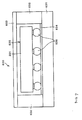
- a description of the package 630 is now given with reference to Fig. 7.
- the package 630 is a two-layer box having a bottom plate 631, side walls 632, and a cap 633.
- a die attach 634 is formed on the inner surface of the bottom plate 631, so that the die attach 634 can be electrically connected to a SAW filter 635 formed on a surface of the piezoelectric substrate 201 that faces the inner surface.
- the SAW filter 635 and the die attach 634 are electrically and mechanically coupled with each other by bumps 636.
- Fig. 8 is a top plan view of the die attach 634 shown in Fig. 7, as viewed from the SAW filter 635 side.
- the die attach 634 has terminals 707 to 710 formed thereon.
- the terminal 707 is specific to an unbalanced signal terminal
- the terminals 708 and 709 are specific to balanced signal terminals
- the terminal 710 is specific to ground terminals.
- the bump locations are indicated by white circles 701 to 706.
- the unbalanced signal terminal 213 shown in Fig. 6 is electrically connected the die attach 634 of the package 630 via the bump 701.
- the balanced signal terminals 214 and 215 are electrically connected the die attach 634 via the bumps 704 and 706, respectively.
- the ground terminals 216, 217, and 218 are electrically connected to the die attach 634 via the bumps 702, 703, and 705, respectively.
- the ground terminal 216 for the IDT 206 is electrically isolated from the ground terminal 218 for the IDT 208 within the package 630 of the chip type.
- the SAW filter can therefore have high balance between the balanced signal terminals 214 and 215.
- a ground terminal is divided into a plurality of sections, for example, two sections, such as the ground terminals 216 and 218, and the bumps are positioned at the four comers of the piezoelectric substrate 201, as shown in Fig. 6, thus allowing the positions for bump bonding to be highly balanced. Because of the highly balanced positions for bump bonding, therefore, the bonding strength between the package 630 and the piezoelectric substrate 201 shown in Fig. 7 can be increased.
- a package 730 having a die attach 734 in which the ground-terminal-specific terminal 710 shown in Fig. 8 is divided into two sections, i.e., ground-terminal-specific terminals 801 and 802, may also be available.
- the ground terminal 216 for the IDT 206 can be electrically isolated from the ground terminal 218 for the IDT 208, again, in the package 730, thereby further improving balance between the balanced signal terminals 214 and 215.
- a SAW filter having, on a piezoelectric substrate, a plurality of IDTs arranged along the SAW propagation direction, and balanced signal input or output terminals
- ground terminals for the IDTs connected to an unbalanced signal input or output terminal of the SAW filter are electrically isolated from each other on the piezoelectric substrate.
- ground terminals electrically isolated from each other on the piezoelectric substrate are electrically connected to different terminals (bonding pads) of a package, thus allowing the ground terminals to be electrically isolated from each other within the package.
- balance can also be improved between the balanced signal terminals.
- the IDT connected to the balanced signal input or output terminals has an even number of electrode fingers in total, and a ground line is inserted between a signal line and a signal terminal which are adjacent to each other in the SAW filter so as to reduce the bridge capacitance between the signal line and the signal terminal.
- balance can also be improved between the balanced signal terminals.
- At least one SAW resonator is connected in series or in parallel or in combination thereof to the SAW filter unit in order to increase the out-of-passband attenuation.
- a receiver (Rx) for reception includes an antenna 601, an antenna duplexer/RF top filter 602, an amplifier 603, Rx inter-stage filter 604, a mixer 605, a first IF filter 606, a mixer 607, a second IF filter 608, a first-and-second local synthesizer 611, a temperature compensated crystal oscillator (TCXO) 612, a divider 613, and a local filter 614.
- TCXO temperature compensated crystal oscillator
- two balanced signals are transmitted from the Rx inter-stage filter 604 to the mixer 605, as indicated by two lines in Fig. 10, in order to maintain balance.
- a transmitter (Tx) for transmission includes the antenna 601, the antenna duplexer/RF top filter 602, a Tx IF filter 621, a mixer 622, a Tx inter-stage filter 623, an amplifier 624, a coupler 625, an isolator 626, and an automatic power control (APC) 627.
- the antenna 601 and the antenna duplexer/RF top filter 602 are shared by the receiver and the transmitter.
- the SAW filter according to the forgoing embodiment may be suitably used as the Rx inter-stage filter 604, the first IF filter 606, the Tx IF filter 621, and the Tx inter-stage filter 623.
- the SAW filter embodying the present invention has both a filtering function and a balance-to-unbalance conversion function, and exhibits a satisfactory characteristic, i.e., an ideal phase characteristic between balanced signals. Therefore, a communication apparatus embodying the present invention, which uses such a SAW filter, has a higher transmission characteristic.
Abstract
Description
- The present invention relates to a surface acoustic wave filter having filtering characteristics and a balance-to-unbalance conversion function, and to a communication apparatus using the surface acoustic wave filter.
- Recently, there has been significant technological progress in reducing the size and weight of cellular telephones. In order to achieve this, in addition to reducing the number and size of components, multi-function components are being increasingly developed. In view of such a background, recent research has been actively conducted on surface acoustic wave (SAW) filters having a balance-to-unbalance conversion function, i.e., a so-called "balun" function, which are used in the RF (radio frequency) stage of cellular telephones. Such SAW filters are used mostly for GSM (global system for mobile communications) compliant devices.
- If a balanced line such as a twin lead feeder is directly coupled to an unbalanced line such as a coaxial cable, an unbalanced current flows, thereby, undesirably, causing the feeder itself to operate as an antenna. A circuit called a balun is thus required for preventing the unbalanced current in order to match the balanced line to the unbalanced line.
- Many patent applications pertaining to SAW filters having a balance-to-unbalance conversion function have been filed. A well-known SAW filter having a balance-to-unbalance conversion function and whose input impedance and output impedance are substantially equal is illustrated in Fig. 11.
- In the SAW filter shown in Fig. 11, a comb-like electrode (also called an interdigital transducer, hereinafter referred to as an "IDT") 102 is formed on a
piezoelectric substrate 100. IDTs 101 and 103 are positioned on the left and right sides of theIDT 102, respectively, in the surface acoustic wave (SAW) propagation direction. -
Reflectors IDTs signal terminals centre IDT 102, respectively. Anunbalanced signal terminal 108 is connected to one set of electrode fingers of each of theIDTs - The SAW filter of this type is called a three-IDT longitudinally coupled resonator SAW filter having a balance-to-unbalance conversion function by performing conversion between the
IDTs - In a SAW filter having a balance-to-unbalance conversion function, it is required that the transmission characteristics in the pass band between the
unbalanced signal terminal 108 and each of thebalanced signal terminals - The extent how the
balanced signal terminals balanced signal terminals - The amplitude balance and the phase balance are defined as follows. If the SAW filter having a balance-to-unbalance conversion function is a three-port device consisting of, for example, a first port corresponding to an unbalanced input terminal and second and third ports corresponding to balanced output terminals, the amplitude balance = [A], where A= |20log(S21)| - |20log(S31)|, and the phase balance = B - 180, where B = |∠S21 - ∠S31|. In the above equations, S21 denotes the transfer coefficient from the first port to the second port, S31 denotes the transfer coefficient from the first port to the third port, and ∥ indicates an absolute value.
- In balance between balanced signal terminals, ideally, the amplitude balance and the phase balance, as defined above, are 0 dB and 0 degree, respectively, in the pass band of a SAW filter.
- However, the SAW filter in the related art shown in Fig. 11 has a problem in that balance between the
balanced signal terminals - Accordingly, it is an object of the present invention to address the problems outlined above. A surface acoustic wave filter embodying the invention has a balance-to-unbalance conversion function and high balance between balanced signal terminals. A communication apparatus using the SAW filter may exhibit high transmission characteristics.
- According to the invention, there is provided a surface acoustic wave filter comprising: a piezoelectric substrate; a filter unit provided on the piezoelectric substrate, said filter unit having an odd number of three or more interdigital transducers including at least two end transducers and a centre transducer, the transducers being arranged along a surface acoustic wave propagation direction, each interdigital transducer having a pair of electrode finger sets; balanced signal terminals connected to the pair of electrode finger sets of the centre interdigital transducer; and an unbalanced signal terminal connected to one electrode finger set of each end interdigital transducers, the end interdigital transducers being different from the centre interdigital transducer, and being located on ends of the filter unit, the other electrode finger set of each end interdigital transducers being connected to a ground, wherein the ground for at least one of the end interdigital transducers is electrically isolated on the piezoelectric substrate from the ground for the other end interdigital transducer.
- In an embodiment of the invention, the balanced signal terminals are connected to the pair of electrode finger sets of the centre IDT positioned at the centre of the IDTs, and the unbalanced signal terminal is connected to one electrode finger set of each of at least two end IDTs different from the centre IDT of the IDTs, thereby implementing a balance-to-unbalance conversion function. Furthermore, the ground for at least one end IDT of the end IDTs is electrically isolated on the piezoelectric substrate from the ground for the other end IDT, thereby making it possible to improve balance between the balanced signal terminals.
- In the SAW filter, a signal line which connects the unbalanced signal terminal to the end IDTs may be provided so as to surround one of the balanced signal terminals, and a ground line may be provided between the signal line and the balanced signal terminal surrounded by the signal line. This allows the bridge capacitance inserted between the signal line and the balanced signal terminal to be reduced by the ground line, thereby making it possible to improve balance between the balanced signal terminals.
- The invention also provides a surface acoustic wave filter comprising: a piezoelectric substrate; a plurality of filter units provided on the piezoelectric substrate, each filter unit having an odd number of three or more interdigital transducers including a first and a second transducer, the transducers arranged along a surface acoustic wave propagation direction, each interdigital transducer having a pair of electrode finger sets; balanced signal terminals being connected to the pair of electrode finger sets of the first centre interdigital transducer located at the centre of a first filter unit of the plurality of filter units; and an unbalanced signal terminal connected to one electrode finger set of the second centre interdigital transducer located at the centre of a second filter unit different from the first filter unit of the plurality of filter units, one electrode finger set of one or more end interdigital transducers different from the first and second centre interdigital transducers in the plurality of filter units being connected to a ground, said end interdigital transducers being located on ends of the first and second filter units, wherein the ground for at least one of the end interdigital transducers is electrically isolated on the piezoelectric substrate from the ground for the other end interdigital transducer.
- In another aspect of the present invention, in a SAW filter, there is provided a piezoelectric substrate, a plurality of filter units provided on the piezoelectric substrate, each unit having an odd number of at least three IDTs along a SAW propagation direction, each IDT having a pair of electrode finger sets. Balanced signal terminals are connected to the pair of electrode finger sets of a first centre IDT which is located at the centre of a first filter unit in the plurality of filter units, and an unbalanced signal terminal is connected to one electrode finger set of a second centre IDT which is located at the centre of a second filter unit different from the first filter unit in the plurality of filter units. One electrode finger set of each of end IDTs different from the first and second centre IDTs in the plurality of filter units is connected to a ground, and the end interdigital transducers being located on ends of the first and second filter units. The ground for at least one of the end IDTs is electrically isolated on the piezoelectric substrate from the ground for the other end IDT.
- In embodiments of this aspect of the invention, the plurality of filter units can increase the out-of-passband attenuation, and can improve filtering characteristics. Furthermore, the balanced signal terminals are connected to the pair of electrode finger sets of the first centre IDT, and the unbalanced signal terminal is connected to one electrode finger set of the second centre IDT, thereby implementing a balance-to-unbalance conversion function. Moreover, the ground for at least one end IDT of the end IDTs is electrically isolated on the piezoelectric substrate from the ground for the other end IDT, thereby improving balance between the balanced signal terminals.
- In the SAW filter, a package which receives the piezoelectric substrate may include a plurality of separate bonding pads for ground terminals. Preferably, the grounds for the end IDTs that sandwich the centre IDT therebetween are connected to the different bonding pads so as to be electrically isolated from each other. With this configuration, the grounds for the end IDTs are separated, again, on the package, thereby making it possible to further improve balance between the balanced signal terminals.
- In the SAW filter, preferably, the IDT connected to the balanced signal terminals has an even number of electrode fingers in total. This enables the number of electrode fingers connected to one balanced signal terminal to be equal to the number of electrode fingers connected to the other balanced signal terminals, thereby further improving balance between the balanced signal terminals.
- In the SAW filter, preferably, at least one SAW resonator is connected at least in series or in parallel to the filter unit. This configuration can increase the out-of-passband attenuation, and can improve filtering characteristics.
- In still another aspect of the present invention, a communication apparatus includes the SAW filter according to any of the above-described configurations. With use of the SAW filter which can implement a balance-to-unbalance conversion function and which has improved balance, the communication apparatus can improve transmission characteristics.
- Embodiments of the invention will now be described, by way of example only, and with reference to the accompanying drawings, in which:
- Fig. 1 is a schematic diagram of a SAW filter according to an embodiment of the present invention;
- Fig. 2 is a graph showing the difference in amplitude balance between the embodiment and a comparative example;
- Fig. 3 is a graph showing the difference in phase balance between the embodiment and the comparative example;
- Fig. 4 is a schematic diagram of a modification of the SAW filter in the embodiment;
- Fig. 5 is a schematic diagram of another modification of the SAW filter in the embodiment;
- Fig. 6 is a schematic diagram of still another modification of the SAW filter in the embodiment, which is produced using a face-down bonding method;
- Fig. 7 is a schematic diagram of a package used in the face-down bonding method;
- Fig. 8 is a plan view of a die attach in the package;
- Fig. 9 is a plan view of a modification of the die attach;
- Fig. 10 is a block diagram of a main part of a communication apparatus according to the present invention; and
- Fig. 11 is a schematic diagram of a SAW filter in the related art having a balance-to-unbalance conversion function.
-
- A SAW filter according to an embodiment of the present invention is now described with reference to Figs. 1 to 10. In the following description, the present invention is discussed in the context of a PCS (personal communication system) reception filter.
- In a SAW filter according to an embodiment of the present invention, as shown in Fig. 1, on a
piezoelectric substrate 201, a longitudinally coupled resonatorSAW filter unit 202, andSAW resonators SAW filter unit 202 are each formed of an aluminum (Al) electrode (foil) produced by a technique such as photolithography. In this embodiment, thepiezoelectric substrate 201 may be a 40±5° Y-cut X-propagating LiTaO3 substrate. - The SAW filter further includes a
package 205 which receives, on the inner surface thereof, thepiezoelectric substrate 201 carrying theSAW filter unit 202 and the like. Thepackage 205 is a rectangular insulator plate made of alumina or the like. Around the periphery of the inner surface of thepackage 205, substantially rectangular thinmetallic bonding pads package 205 that is the same as the surface on which thepiezoelectric substrate 201 rests. Thebonding pads piezoelectric substrate 201. - A substantially rectangular thin
metallic bonding pad 222 for an unbalanced signal input is further formed on this inner surface of thepackage 205 between thebonding pads package 205, substantially rectangular thinmetallic bonding pads bonding pad 225 therebetween. - The
SAW filter unit 202 includes acentre IDT 207, and IDTs (end IDTs) 206 and 208, which sandwich theIDT 207 therebetween from both sides in the SAW propagation direction. TheSAW filter unit 202 further includesreflectors IDTs - The
IDTs - In any of the
IDTs piezoelectric substrate 201. The surface acoustic wave then propagates across the surface of thepiezoelectric substrate 201 in a bi-directional manner in the width direction of the electrode fingers, i.e., in the direction orthogonal to the length of the electrode fingers. In an IDT to which no electrical signal is input, the potential difference produced on the surface of thepiezoelectric substrate 201 by the propagating surface acoustic wave is detected by the electrode fingers, and is converted into an output electrical signal, which is then output. - In the
IDTs reflectors - As is apparent from Fig. 1, in the
SAW filter unit 202, the pitch between some electrode fingers (narrower-pitch electrode fingers) near the portion (indicated by a portion 211) where theIDTs IDTs IDTs IDTs - On the
piezoelectric substrate 201,balanced signal terminals IDT 207. On thepiezoelectric substrate 201, anunbalanced signal terminal 213 is electrically connected to one electrode finger portion in each of theIDTs SAW resonators signal line 219. Thesignal line 219 is substantially C-shaped so as to surround thebalanced signal terminal 214. - A substantially C-shaped
ground line 220 is inserted on thepiezoelectric substrate 201 so as to isolate thesignal line 219 and thebalanced signal terminal 214 from each other. Theground line 220 allows the bridge capacitance between thesignal line 219 and thebalanced signal terminal 214 to be reduced, thereby improving balance between thebalanced signal terminals - The
signal line 219 and theground line 220 are each formed of an aluminum (Al) electrode (foil) produced by a technique such as photolithography. - Thin
metallic ground terminals piezoelectric substrate 201. Theground terminal 216 is electrically connected to the other electrode finger portion of theIDT 206. Theground terminal 217 is located on theground line 220, and is electrically connected to theground line 220. Theground terminal 218 is electrically connected to the other electrode finger portion of theIDT 208. - A feature of the present embodiment is that the
ground terminal 216 for theIDT 206 is electrically isolated from theground terminal 218 for theIDT 208 on thepiezoelectric substrate 201. - The
SAW filter unit 202 formed on thepiezoelectric substrate 201 is electrically connected to thepackage 205 by a wire bonding method. Theunbalanced signal terminal 213 is electrically connected to thebonding pad 222 of thepackage 205 via abonding wire 227. Thebalanced signal terminal 214 is electrically connected to thebonding pad 224 via abonding wire 228. Thebalanced signal terminal 215 is electrically connected to thebonding pad 226 via abonding wire 229. - The
ground terminal 216 is electrically connected to thebonding pad 223 via abonding wire 230. Theground terminals bonding pad 225 viabonding wires - Another feature of the present embodiment is that the
ground terminals different bonding pads bonding pads package 205. - Where the wavelength defined by the pitch between the narrower-pitch electrode fingers is indicated by λI2 (indicated by the
portions SAW filter unit 202 is as follows: - interdigital length W: 53.7 λI1;
- number of electrode fingers of the IDT 206: 29(4)
- number of electrode fingers of the IDT 207: (4)44(4)
- number of electrode fingers of the IDT 208: (4)29
- (the number in parentheses indicates the number of narrower-pitch electrode fingers);
IDT wavelength λI1: 2.05 µm
λI2: 1.86 µm; - reflector wavelength λR: 2.06 µm;
- number of electrode fingers of reflector: 100;
- centre-to-centre distance between electrode fingers of IDTs: 0.50 λI2;
- centre-to-centre distance between electrode fingers of IDT and reflector: 0.47 λR;
- duty: 0.60 (for IDT and reflector); and
- electrode thickness: 0.080 λI1.
-
- The specific design of the
SAW resonator 203 is as follows: - interdigital length W: 49.1 λ;
- number of electrode fingers of IDT: 401;
- wavelength λ (for IDT and reflector): 2.04 µm;
- number of electrode fingers of reflector: 30;
- pitch between IDT and reflector: 0.50 λ;
- duty: 0.60 (for IDT and reflector); and
- electrode thickness: 0.080 λ.
-
- The specific design of the
SAW resonator 204 is as follows: - interdigital length W: 40.6 λ;
- number of electrode fingers of IDT: 241;
- wavelength λ (for IDT and reflector): 1.97 µm;
- number of electrode fingers of reflector: 30;
- pitch between IDT and reflector: 0.50 λ;
- duty: 0.60 (for IDT and reflector); and
- electrode thickness: 0.084 λ.
-
- The operations and advantages of the SAW filter in the present embodiment are now described. Figs. 2 and 3 are graphs showing the amplitude balance and the phase balance between the
balanced signal terminals ground terminals - The frequency of the pass band of a PCS reception filter ranges from 1930 MHz to 1990 MHz. The maximum amplitude balance in this frequency range is 2.4 dB for the comparative example, while it is 2.0 dB for the present embodiment. In the present embodiment, therefore, the amplitude balance is improved by about 0.4 dB.
- The maximum phase balance in the frequency range is 8° for the comparative example, while it is 7° for the present embodiment. In the present embodiment, therefore, the amplitude balance is improved by about 1°. This is caused by electrically isolating the
ground terminal 216 for theIDT 206 from theground terminal 218 for theIDT 208 on thepiezoelectric substrate 201. - The advantage of improved balance between the
balanced signal terminals ground terminals different bonding pads package 205, respectively. - For example, in Fig. 1, if both the
ground terminals bonding pad 223, or if thebonding pads package 205, it has been found that balance between thebalanced signal terminals - According to the present embodiment, therefore, the SAW filter having a balance-to-unbalance conversion function is configured so that ground terminals for the IDTs connected to the unbalanced signal input or output terminal are electrically isolated from each other on a piezoelectric substrate or within a package. Consequently, the SAW filter according to the present embodiment can have improved balance between balanced signal terminals compared with a SAW filter in the comparative example or a SAW filter in the related art.
- In the present embodiment, the
centre IDT 207 of the threeIDTs SAW filter unit 202 has an even number of electrode fingers in total. Thus, the number of electrode fingers connected to thebalanced signal terminal 214 can be equal to the number of electrode fingers connected to thebalanced signal terminal 215, thereby further improving balance between thebalanced signal terminals - As in the present embodiment, preferably, the
centre IDT 207 has an even number of electrode fingers in total in order to further improve balance between thebalanced signal terminals - In the present embodiment, the
ground line 220 is inserted between thesignal line 219 and thebalanced signal terminal 214. Thus, the bridge capacitance can be reduced between thesignal line 219 and thebalanced signal terminal 214, thereby further improving balance between thebalanced signal terminals - As in the present embodiment, preferably, the
ground line 220 is inserted to a portion where thesignal line 219 is adjacent to thebalanced signal terminal 214 in order to further improve balance between thebalanced signal terminals ground line 220 inserted, however, the advantages of the present invention would also be achieved. - The present invention has been discussed in context of a SAW filter including two
SAW resonators SAW filter unit 202 having threeIDTs centre IDT 207 in theSAW filter unit 202. However, the present invention is not limited to this form, and the advantages of the present invention would also be achieved by a SAW filter having balanced signal terminals using any configuration. - For example, a longitudinally coupled resonator SAW filter unit having more than four IDTs or a SAW filter unit having a SAW resonator connected in parallel thereto would also achieve advantages similar to those of the present invention. A SAW filter, as shown in Fig. 4, in which an unbalanced signal is input (output) from the opposite sides of IDTs of a longitudinally coupled resonator SAW filter unit, may be used. In this SAW filter,
ground terminals piezoelectric substrate 201 or within thepackage 205, thereby achieving the advantages of the present invention. - A SAW filter, as shown in Fig. 5, in which longitudinally coupled resonator
SAW filter units ground terminals IDTs centre IDT 207 therebetween, and/orground terminals IDTs centre IDT 407 therebetween may be electrically isolated from each other at least on thepiezoelectric substrate 201 or within thepackage 205, thereby achieving the advantages of the present invention. - Besides the SAW filter in the present embodiment of the floating balanced type that it does not have an electrically neutral point between the
balanced signal terminals balanced signal terminals balanced signal terminals - In the SAW filter according to the present embodiment, the
piezoelectric substrate 201 is a 40±5° Y-cut X-propagating LiTaO3 substrate; however, the present invention is not limited thereto as long as the advantages of the present invention are achieved. Thepiezoelectric substrate 201 may be made of 64° to 72° Y-cut X-propagating LiNbO3, 41° Y-cut X-propagating LiNbO3, or the like. - A SAW filter received in a package by a face-down bonding method is now described with reference to Figs. 6 to 9. Fig. 6 shows the layout of components formed on the
piezoelectric substrate 201 shown in Fig. 1, such as electrodes and terminals, which is modified so that these components are introduced into apackage 630 using a face-down bonding method. The longitudinally coupled resonatorSAW filter unit 202 and theSAW resonators - The location of the terminals is modified so that they may be received in the
package 630, although theground terminal 216 for theIDT 206 is electrically isolated from the terminal 218 for theIDT 208 in the same way as in Fig. 1. A description of thepackage 630 is now given with reference to Fig. 7. - The
package 630 is a two-layer box having abottom plate 631,side walls 632, and acap 633. A die attach 634 is formed on the inner surface of thebottom plate 631, so that the die attach 634 can be electrically connected to aSAW filter 635 formed on a surface of thepiezoelectric substrate 201 that faces the inner surface. TheSAW filter 635 and the die attach 634 are electrically and mechanically coupled with each other bybumps 636. - Fig. 8 is a top plan view of the die attach 634 shown in Fig. 7, as viewed from the
SAW filter 635 side. The die attach 634 hasterminals 707 to 710 formed thereon. The terminal 707 is specific to an unbalanced signal terminal, theterminals white circles 701 to 706. Theunbalanced signal terminal 213 shown in Fig. 6 is electrically connected the die attach 634 of thepackage 630 via thebump 701. Thebalanced signal terminals bumps ground terminals bumps - In the SAW filter produced by a face-down bonding method, therefore, the
ground terminal 216 for theIDT 206 is electrically isolated from theground terminal 218 for theIDT 208 within thepackage 630 of the chip type. The SAW filter can therefore have high balance between thebalanced signal terminals - A ground terminal is divided into a plurality of sections, for example, two sections, such as the
ground terminals piezoelectric substrate 201, as shown in Fig. 6, thus allowing the positions for bump bonding to be highly balanced. Because of the highly balanced positions for bump bonding, therefore, the bonding strength between thepackage 630 and thepiezoelectric substrate 201 shown in Fig. 7 can be increased. - As an alternative, as shown in Fig. 9, a
package 730 having a die attach 734 in which the ground-terminal-specific terminal 710 shown in Fig. 8 is divided into two sections, i.e., ground-terminal-specific terminals ground terminal 216 for theIDT 206 can be electrically isolated from theground terminal 218 for theIDT 208, again, in thepackage 730, thereby further improving balance between thebalanced signal terminals - According to embodiments of the present invention, therefore, in a SAW filter having, on a piezoelectric substrate, a plurality of IDTs arranged along the SAW propagation direction, and balanced signal input or output terminals, ground terminals for the IDTs connected to an unbalanced signal input or output terminal of the SAW filter are electrically isolated from each other on the piezoelectric substrate. Thus, balance can be improved between the balanced signal terminals.
- The ground terminals electrically isolated from each other on the piezoelectric substrate are electrically connected to different terminals (bonding pads) of a package, thus allowing the ground terminals to be electrically isolated from each other within the package. Thus, balance can also be improved between the balanced signal terminals.
- The IDT connected to the balanced signal input or output terminals has an even number of electrode fingers in total, and a ground line is inserted between a signal line and a signal terminal which are adjacent to each other in the SAW filter so as to reduce the bridge capacitance between the signal line and the signal terminal. Thus, balance can also be improved between the balanced signal terminals.
- Preferably, at least one SAW resonator is connected in series or in parallel or in combination thereof to the SAW filter unit in order to increase the out-of-passband attenuation.
- A description is now given, with reference to Fig. 10, of a
communication apparatus 600 using a SAW filter according to the present embodiment. In thecommunication apparatus 600, a receiver (Rx) for reception includes anantenna 601, an antenna duplexer/RF top filter 602, anamplifier 603, Rxinter-stage filter 604, amixer 605, a first IFfilter 606, amixer 607, a second IFfilter 608, a first-and-secondlocal synthesizer 611, a temperature compensated crystal oscillator (TCXO) 612, adivider 613, and alocal filter 614. - Preferably, two balanced signals are transmitted from the Rx
inter-stage filter 604 to themixer 605, as indicated by two lines in Fig. 10, in order to maintain balance. - In the
communication apparatus 600, a transmitter (Tx) for transmission includes theantenna 601, the antenna duplexer/RF top filter 602, a Tx IFfilter 621, amixer 622, a Txinter-stage filter 623, anamplifier 624, acoupler 625, anisolator 626, and an automatic power control (APC) 627. Theantenna 601 and the antenna duplexer/RF top filter 602 are shared by the receiver and the transmitter. - The SAW filter according to the forgoing embodiment may be suitably used as the Rx
inter-stage filter 604, the first IFfilter 606, the Tx IFfilter 621, and the Txinter-stage filter 623. - The SAW filter embodying the present invention has both a filtering function and a balance-to-unbalance conversion function, and exhibits a satisfactory characteristic, i.e., an ideal phase characteristic between balanced signals. Therefore, a communication apparatus embodying the present invention, which uses such a SAW filter, has a higher transmission characteristic.
Claims (9)
- A surface acoustic wave filter comprising:wherein the ground for at least one of the end interdigital transducers is electrically isolated on the piezoelectric substrate from the ground for the other end interdigital transducer.a piezoelectric substrate;a filter unit provided on the piezoelectric substrate, said filter unit having an odd number of at least three interdigital transducers along a surface acoustic wave propagation direction, each interdigital transducer having a pair of electrode finger sets;balanced signal terminals being connected to the pair of electrode finger sets of the center interdigital transducer in the interdigital transducers; andan unbalanced signal terminal connected to one electrode finger set of each of at least two end interdigital transducers in the interdigital transducers, said at least two end interdigital transducers being different from the center interdigital transducer, and being located on ends of the filter unit,the other electrode finger set of each of said at least two end interdigital transducers being connected to a ground,
- A surface acoustic wave filter according to claim 1,
wherein a signal line for connecting the unbalanced signal terminal to the end interdigital transducers is provided so as to surround one of the balanced signal terminals; and
a ground line is provided between the signal line and the balanced signal terminal surrounded by the signal line. - A surface acoustic wave filter comprising:wherein the ground for at least one of the end interdigital transducers is electrically isolated on the piezoelectric substrate from the ground for the other end interdigital transducer.a piezoelectric substrate;a plurality of filter units provided on the piezoelectric substrate, each filter unit having an odd number of at least three interdigital transducers along a surface acoustic wave propagation direction, each interdigital transducer having a pair of electrode finger sets;balanced signal terminals being connected to the pair of electrode finger sets of a first center interdigital transducer which is located at the center of a first filter unit in the plurality of filter units; andan unbalanced signal terminal connected to one electrode finger set of a second center interdigital transducer which is located at the center of a second filter unit different from the first filter unit in the plurality of filter units,one electrode finger set of each of end interdigital transducers different from the first and second center interdigital transducers in the plurality of filter units being connected to a ground, said end interdigital transducers being located on ends of the first and second filter units,
- A surface acoustic wave filter according to claim 1 or 3, wherein a package which receives the piezoelectric substrate includes a plurality of separate bonding pads for ground terminals, and the grounds for the end interdigital transducers that sandwich the centre interdigital transducer therebetween are connected to the different bonding pads so as to be electrically isolated from each other.
- A surface acoustic wave filter according to claim 1 or 3, wherein the interdigital transducer connected to the balanced signal terminals has an even number of electrode fingers in total.
- A surface acoustic wave filter according to claim 1 or 3, wherein at least one surface acoustic wave resonator is connected at least one of in series and in parallel to the filter unit.
- A communication apparatus comprising the surface acoustic wave filter according to any preceding claim.
- A surface acoustic wave filter comprising:wherein the ground for at least one of the end interdigital transducers is electrically isolated on the piezoelectric substrate from the ground for the other end interdigital transducer.a piezoelectric substrate;a filter unit provided on the piezoelectric substrate, said filter unit having an odd number of three or more interdigital transducers including at least two end transducers and a centre transducer, the transducers being arranged along a surface acoustic wave propagation direction, each interdigital transducer having a pair of electrode finger sets;balanced signal terminals connected to the pair of electrode finger sets of the centre interdigital transducer; andan unbalanced signal terminal connected to one electrode finger set of each end interdigital transducers, the end interdigital transducers being different from the centre interdigital transducer, and being located on ends of the filter unit,the other electrode finger set of each end interdigital transducers being connected to a ground,
- A surface acoustic wave filter comprising:wherein the ground for at least one of the end interdigital transducers is electrically isolated on the piezoelectric substrate from the ground for the other end interdigital transducer.a piezoelectric substrate;a plurality of filter units provided on the piezoelectric substrate, each filter unit having an odd number of three or more interdigital transducers including a first and a second transducer, the transducers arranged along a surface acoustic wave propagation direction, each interdigital transducer having a pair of electrode finger sets;balanced signal terminals being connected to the pair of electrode finger sets of the first centre interdigital transducer located at the centre of a first filter unit of the plurality of filter units; andan unbalanced signal terminal connected to one electrode finger set of the second centre interdigital transducer located at the centre of a second filter unit different from the first filter unit of the plurality of filter units,one electrode finger set of one or more end interdigital transducers different from the first and second centre interdigital transducers in the plurality of filter units being connected to a ground, said end interdigital transducers being located on ends of the first and second filter units,
Priority Applications (1)
| Application Number | Priority Date | Filing Date | Title |
|---|---|---|---|
| EP06011341A EP1710912A3 (en) | 2001-08-09 | 2002-08-09 | Surface acoustic wave filter and communication apparatus |
Applications Claiming Priority (4)
| Application Number | Priority Date | Filing Date | Title |
|---|---|---|---|
| JP2001242846 | 2001-08-09 | ||
| JP2001242846 | 2001-08-09 | ||
| JP2002159137 | 2002-05-31 | ||
| JP2002159137A JP3864850B2 (en) | 2001-08-09 | 2002-05-31 | Surface acoustic wave filter, communication device |
Related Child Applications (1)
| Application Number | Title | Priority Date | Filing Date |
|---|---|---|---|
| EP06011341A Division EP1710912A3 (en) | 2001-08-09 | 2002-08-09 | Surface acoustic wave filter and communication apparatus |
Publications (2)
| Publication Number | Publication Date |
|---|---|
| EP1289136A2 true EP1289136A2 (en) | 2003-03-05 |
| EP1289136A3 EP1289136A3 (en) | 2005-06-15 |
Family
ID=26620314
Family Applications (2)
| Application Number | Title | Priority Date | Filing Date |
|---|---|---|---|
| EP06011341A Withdrawn EP1710912A3 (en) | 2001-08-09 | 2002-08-09 | Surface acoustic wave filter and communication apparatus |
| EP02255590A Withdrawn EP1289136A3 (en) | 2001-08-09 | 2002-08-09 | Surface acoustic wave filter and communication apparatus. |
Family Applications Before (1)
| Application Number | Title | Priority Date | Filing Date |
|---|---|---|---|
| EP06011341A Withdrawn EP1710912A3 (en) | 2001-08-09 | 2002-08-09 | Surface acoustic wave filter and communication apparatus |
Country Status (6)
| Country | Link |
|---|---|
| US (1) | US6756867B2 (en) |
| EP (2) | EP1710912A3 (en) |
| JP (1) | JP3864850B2 (en) |
| KR (1) | KR100489777B1 (en) |
| CN (1) | CN1223084C (en) |
| TW (1) | TWI259655B (en) |
Cited By (2)
| Publication number | Priority date | Publication date | Assignee | Title |
|---|---|---|---|---|
| EP1783901A2 (en) | 2005-10-26 | 2007-05-09 | Fujitsu Media Devices Limited | Surface acoustic wave device |
| EP1533895A3 (en) * | 2003-11-21 | 2010-01-06 | Fujitsu Media Devices Limited | Surface acoustic wave filter and wireless device that employs the same |
Families Citing this family (11)
| Publication number | Priority date | Publication date | Assignee | Title |
|---|---|---|---|---|
| EP1737126A4 (en) * | 2004-04-16 | 2008-01-16 | Epson Toyocom Corp | Balanced type surface acoustic wave filter |
| JP3993579B2 (en) * | 2004-04-28 | 2007-10-17 | 富士通メディアデバイス株式会社 | Balanced output type filter |
| JP3918102B2 (en) | 2004-06-30 | 2007-05-23 | 株式会社村田製作所 | Balanced elastic wave filter and elastic wave filter device |
| CN101682313B (en) | 2007-05-28 | 2012-09-26 | 株式会社村田制作所 | Duplexer and elastic wave device |
| CN101874348B (en) | 2008-03-27 | 2013-11-06 | 株式会社村田制作所 | Elastic wave filter device |
| CN102804601B (en) * | 2009-06-26 | 2015-03-04 | 株式会社村田制作所 | Elastic wave device and duplexer |
| JP2012065272A (en) * | 2010-09-17 | 2012-03-29 | Nippon Dempa Kogyo Co Ltd | Elastic wave device |
| JP5825444B2 (en) * | 2012-09-28 | 2015-12-02 | 株式会社村田製作所 | Elastic wave device and manufacturing method thereof |
| JP6558445B2 (en) * | 2015-11-18 | 2019-08-14 | 株式会社村田製作所 | Elastic wave filter, duplexer, and elastic wave filter module |
| KR102372785B1 (en) * | 2017-09-05 | 2022-03-08 | 가부시키가이샤 무라타 세이사쿠쇼 | Filter device and manufacturing method of filter device |
| GB2605531A (en) * | 2019-11-27 | 2022-10-05 | Univ Tohoku | Energy confinement in acoustic wave devices |
Citations (2)
| Publication number | Priority date | Publication date | Assignee | Title |
|---|---|---|---|---|
| JP2002314362A (en) * | 2001-04-17 | 2002-10-25 | Murata Mfg Co Ltd | Surface acoustic wave filter and communication equipment |
| JP2002359537A (en) * | 2001-06-01 | 2002-12-13 | Murata Mfg Co Ltd | Elastic surface wave filter and communication device |
Family Cites Families (20)
| Publication number | Priority date | Publication date | Assignee | Title |
|---|---|---|---|---|
| EP0637872B1 (en) * | 1993-08-06 | 2000-02-23 | Kinseki Limited | Surface acoustic wave device |
| US5666091A (en) * | 1995-03-20 | 1997-09-09 | Hitachi Media Electronics Co., Ltd. | Structure of surface acoustic wave filter |
| GB2306821B (en) * | 1995-11-03 | 2000-05-31 | Advanced Saw Prod Sa | Electro-acoustic device |
| EP0809357B1 (en) * | 1996-05-23 | 1999-12-15 | Matsushita Electric Industrial Co., Ltd. | Surface acoustic wave filter and multistage surface acoustic wave filter |
| JP3239064B2 (en) * | 1996-05-28 | 2001-12-17 | 富士通株式会社 | Surface acoustic wave device |
| JP3131568B2 (en) * | 1996-09-26 | 2001-02-05 | 株式会社東芝 | Surface acoustic wave device |
| JP3224202B2 (en) * | 1996-11-28 | 2001-10-29 | 富士通株式会社 | Surface acoustic wave device |
| JP3376355B2 (en) * | 1997-07-18 | 2003-02-10 | 株式会社東芝 | Surface acoustic wave filter |
| JP3196693B2 (en) * | 1997-08-05 | 2001-08-06 | 日本電気株式会社 | Surface acoustic wave device and method of manufacturing the same |
| JPH11239035A (en) * | 1998-02-20 | 1999-08-31 | Toyo Commun Equip Co Ltd | Saw filter |
| JP3289674B2 (en) * | 1998-05-21 | 2002-06-10 | 株式会社村田製作所 | Surface wave filter device, duplexer, communication device |
| JP2000209061A (en) * | 1999-01-12 | 2000-07-28 | Toshiba Corp | Surface acoustic wave element and device |
| JP2000332563A (en) * | 1999-05-19 | 2000-11-30 | Matsushita Electric Ind Co Ltd | Saw filter |
| JP3382920B2 (en) * | 2000-06-30 | 2003-03-04 | 沖電気工業株式会社 | Resonator type surface acoustic wave filter |
| JP3478260B2 (en) * | 2000-10-27 | 2003-12-15 | 株式会社村田製作所 | Surface acoustic wave filter and communication device |
| JP3384403B2 (en) * | 2001-03-01 | 2003-03-10 | 株式会社村田製作所 | Surface acoustic wave device, communication device |
| US6815868B2 (en) * | 2001-04-09 | 2004-11-09 | Murata Manufacturing Co., Ltd. | Surface acoustic wave apparatus and communication unit |
| JP3509771B2 (en) * | 2001-04-18 | 2004-03-22 | 株式会社村田製作所 | Surface acoustic wave filter device, communication device |
| JP3435147B2 (en) * | 2001-04-23 | 2003-08-11 | 富士通株式会社 | Surface acoustic wave device |
| JP3685102B2 (en) * | 2001-07-27 | 2005-08-17 | 株式会社村田製作所 | Surface acoustic wave filter, communication device |
-
2002
- 2002-05-31 JP JP2002159137A patent/JP3864850B2/en not_active Expired - Lifetime
- 2002-07-29 TW TW091116919A patent/TWI259655B/en not_active IP Right Cessation
- 2002-08-08 KR KR10-2002-0046756A patent/KR100489777B1/en active IP Right Grant
- 2002-08-09 EP EP06011341A patent/EP1710912A3/en not_active Withdrawn
- 2002-08-09 EP EP02255590A patent/EP1289136A3/en not_active Withdrawn
- 2002-08-09 US US10/215,024 patent/US6756867B2/en not_active Expired - Lifetime
- 2002-08-09 CN CNB021419825A patent/CN1223084C/en not_active Expired - Lifetime
Patent Citations (2)
| Publication number | Priority date | Publication date | Assignee | Title |
|---|---|---|---|---|
| JP2002314362A (en) * | 2001-04-17 | 2002-10-25 | Murata Mfg Co Ltd | Surface acoustic wave filter and communication equipment |
| JP2002359537A (en) * | 2001-06-01 | 2002-12-13 | Murata Mfg Co Ltd | Elastic surface wave filter and communication device |
Cited By (5)
| Publication number | Priority date | Publication date | Assignee | Title |
|---|---|---|---|---|
| EP1533895A3 (en) * | 2003-11-21 | 2010-01-06 | Fujitsu Media Devices Limited | Surface acoustic wave filter and wireless device that employs the same |
| EP1783901A2 (en) | 2005-10-26 | 2007-05-09 | Fujitsu Media Devices Limited | Surface acoustic wave device |
| EP1783901A3 (en) * | 2005-10-26 | 2008-01-23 | Fujitsu Media Devices Limited | Surface acoustic wave device |
| US7515017B2 (en) | 2005-10-26 | 2009-04-07 | Fujitsu Media Devices Limited | Surface acoustic wave device utilizing a terminal routing pattern |
| CN1956325B (en) * | 2005-10-26 | 2010-05-12 | 富士通媒体部品株式会社 | Surface acoustic wave device |
Also Published As
| Publication number | Publication date |
|---|---|
| EP1710912A2 (en) | 2006-10-11 |
| TWI259655B (en) | 2006-08-01 |
| US20030030512A1 (en) | 2003-02-13 |
| KR20030014647A (en) | 2003-02-19 |
| KR100489777B1 (en) | 2005-05-16 |
| CN1402428A (en) | 2003-03-12 |
| US6756867B2 (en) | 2004-06-29 |
| EP1710912A3 (en) | 2009-02-25 |
| JP2003124782A (en) | 2003-04-25 |
| EP1289136A3 (en) | 2005-06-15 |
| JP3864850B2 (en) | 2007-01-10 |
| CN1223084C (en) | 2005-10-12 |
Similar Documents
| Publication | Publication Date | Title |
|---|---|---|
| US7283016B2 (en) | Balanced acoustic wave filter and acoustic wave filter | |
| US6720842B2 (en) | Surface acoustic wave filter device having first through third surface acoustic wave filter elements | |
| KR100622258B1 (en) | Surface-acoustic-wave apparatus | |
| US6816036B2 (en) | Surface acoustic wave filter and communication apparatus | |
| US7116189B2 (en) | Surface acoustic wave device and communication apparatus including the same | |
| US6753641B2 (en) | Surface acoustic wave device and communication device | |
| EP2254244B1 (en) | Balance filter and duplexer | |
| US6756867B2 (en) | Surface acoustic wave filter and communication apparatus | |
| JP3743341B2 (en) | Surface acoustic wave device | |
| KR100503957B1 (en) | Surface acoustic wave device | |
| JP3478260B2 (en) | Surface acoustic wave filter and communication device | |
| US6943649B2 (en) | Surface acoustic wave filter with a ground pattern partially surrounding a signal pad and communication device using same | |
| KR20030063207A (en) | Surface acoustic wave device and communication apparatus including the same | |
| JP2005102328A (en) | Acoustic surface wave device |
Legal Events
| Date | Code | Title | Description |
|---|---|---|---|
| PUAI | Public reference made under article 153(3) epc to a published international application that has entered the european phase |
Free format text: ORIGINAL CODE: 0009012 |
|
| 17P | Request for examination filed |
Effective date: 20020909 |
|
| AK | Designated contracting states |
Kind code of ref document: A2 Designated state(s): AT BE BG CH CY CZ DE DK EE ES FI FR GB GR IE IT LI LU MC NL PT SE SK TR Designated state(s): AT BE BG CH CY CZ DE DK EE ES FI FR GB GR IE IT LI LU MC NL PT SE SK TR |
|
| AX | Request for extension of the european patent |
Extension state: AL LT LV MK RO SI |
|
| PUAL | Search report despatched |
Free format text: ORIGINAL CODE: 0009013 |
|
| RIC1 | Information provided on ipc code assigned before grant |
Ipc: 7H 03H 9/02 B Ipc: 7H 03H 9/64 A |
|
| AK | Designated contracting states |
Kind code of ref document: A3 Designated state(s): AT BE BG CH CY CZ DE DK EE ES FI FR GB GR IE IT LI LU MC NL PT SE SK TR |
|
| AX | Request for extension of the european patent |
Extension state: AL LT LV MK RO SI |
|
| AKX | Designation fees paid |
Designated state(s): DE FR GB |
|
| RAP1 | Party data changed (applicant data changed or rights of an application transferred) |
Owner name: MURATA MANUFACTURING CO., LTD. |
|
| STAA | Information on the status of an ep patent application or granted ep patent |
Free format text: STATUS: THE APPLICATION IS DEEMED TO BE WITHDRAWN |
|
| 18D | Application deemed to be withdrawn |
Effective date: 20090424 |