EP1289071A2 - Contact with an improved locking element - Google Patents
Contact with an improved locking element Download PDFInfo
- Publication number
- EP1289071A2 EP1289071A2 EP02018121A EP02018121A EP1289071A2 EP 1289071 A2 EP1289071 A2 EP 1289071A2 EP 02018121 A EP02018121 A EP 02018121A EP 02018121 A EP02018121 A EP 02018121A EP 1289071 A2 EP1289071 A2 EP 1289071A2
- Authority
- EP
- European Patent Office
- Prior art keywords
- contact
- cover
- face
- positioner
- locking element
- Prior art date
- Legal status (The legal status is an assumption and is not a legal conclusion. Google has not performed a legal analysis and makes no representation as to the accuracy of the status listed.)
- Granted
Links
Images




Classifications
-
- H—ELECTRICITY
- H01—ELECTRIC ELEMENTS
- H01R—ELECTRICALLY-CONDUCTIVE CONNECTIONS; STRUCTURAL ASSOCIATIONS OF A PLURALITY OF MUTUALLY-INSULATED ELECTRICAL CONNECTING ELEMENTS; COUPLING DEVICES; CURRENT COLLECTORS
- H01R13/00—Details of coupling devices of the kinds covered by groups H01R12/70 or H01R24/00 - H01R33/00
- H01R13/02—Contact members
- H01R13/15—Pins, blades or sockets having separate spring member for producing or increasing contact pressure
- H01R13/187—Pins, blades or sockets having separate spring member for producing or increasing contact pressure with spring member in the socket
-
- H—ELECTRICITY
- H01—ELECTRIC ELEMENTS
- H01R—ELECTRICALLY-CONDUCTIVE CONNECTIONS; STRUCTURAL ASSOCIATIONS OF A PLURALITY OF MUTUALLY-INSULATED ELECTRICAL CONNECTING ELEMENTS; COUPLING DEVICES; CURRENT COLLECTORS
- H01R13/00—Details of coupling devices of the kinds covered by groups H01R12/70 or H01R24/00 - H01R33/00
- H01R13/40—Securing contact members in or to a base or case; Insulating of contact members
- H01R13/42—Securing in a demountable manner
- H01R13/422—Securing in resilient one-piece base or case, e.g. by friction; One-piece base or case formed with resilient locking means
- H01R13/4223—Securing in resilient one-piece base or case, e.g. by friction; One-piece base or case formed with resilient locking means comprising integral flexible contact retaining fingers
-
- H—ELECTRICITY
- H01—ELECTRIC ELEMENTS
- H01R—ELECTRICALLY-CONDUCTIVE CONNECTIONS; STRUCTURAL ASSOCIATIONS OF A PLURALITY OF MUTUALLY-INSULATED ELECTRICAL CONNECTING ELEMENTS; COUPLING DEVICES; CURRENT COLLECTORS
- H01R13/00—Details of coupling devices of the kinds covered by groups H01R12/70 or H01R24/00 - H01R33/00
- H01R13/46—Bases; Cases
- H01R13/52—Dustproof, splashproof, drip-proof, waterproof, or flameproof cases
- H01R13/5205—Sealing means between cable and housing, e.g. grommet
- H01R13/5208—Sealing means between cable and housing, e.g. grommet having at least two cable receiving openings
-
- H—ELECTRICITY
- H01—ELECTRIC ELEMENTS
- H01R—ELECTRICALLY-CONDUCTIVE CONNECTIONS; STRUCTURAL ASSOCIATIONS OF A PLURALITY OF MUTUALLY-INSULATED ELECTRICAL CONNECTING ELEMENTS; COUPLING DEVICES; CURRENT COLLECTORS
- H01R13/00—Details of coupling devices of the kinds covered by groups H01R12/70 or H01R24/00 - H01R33/00
- H01R13/02—Contact members
- H01R13/10—Sockets for co-operation with pins or blades
- H01R13/11—Resilient sockets
- H01R13/113—Resilient sockets co-operating with pins or blades having a rectangular transverse section
-
- H—ELECTRICITY
- H01—ELECTRIC ELEMENTS
- H01R—ELECTRICALLY-CONDUCTIVE CONNECTIONS; STRUCTURAL ASSOCIATIONS OF A PLURALITY OF MUTUALLY-INSULATED ELECTRICAL CONNECTING ELEMENTS; COUPLING DEVICES; CURRENT COLLECTORS
- H01R13/00—Details of coupling devices of the kinds covered by groups H01R12/70 or H01R24/00 - H01R33/00
- H01R13/40—Securing contact members in or to a base or case; Insulating of contact members
- H01R13/42—Securing in a demountable manner
- H01R13/436—Securing a plurality of contact members by one locking piece or operation
- H01R13/4364—Insertion of locking piece from the front
-
- H—ELECTRICITY
- H01—ELECTRIC ELEMENTS
- H01R—ELECTRICALLY-CONDUCTIVE CONNECTIONS; STRUCTURAL ASSOCIATIONS OF A PLURALITY OF MUTUALLY-INSULATED ELECTRICAL CONNECTING ELEMENTS; COUPLING DEVICES; CURRENT COLLECTORS
- H01R13/00—Details of coupling devices of the kinds covered by groups H01R12/70 or H01R24/00 - H01R33/00
- H01R13/46—Bases; Cases
- H01R13/52—Dustproof, splashproof, drip-proof, waterproof, or flameproof cases
- H01R13/5219—Sealing means between coupling parts, e.g. interfacial seal
Definitions
- the invention relates to contacts for plug housings. More specifically, the invention relates to a contact having a locking element with a cover that prevents damage to a seal in a plug housing during insertion and removal of the contact.
- Plug housings are commonly provided with seals that protect contacts that are received in the plug housings from unwanted moisture.
- the conventional plug housing is already equipped with the seal before insertion of the contact.
- the seal is provided with openings that allow the contact to pass through the seal and into a receiving region of the plug housing.
- the contact is guided through the opening of the seal during production of the plug housing.
- Known contacts have an inclined guide face with which the seal is raised or enlarged during insertion of the contact to prevent tearing or widening of the seal.
- One such plug housing having a seal is taught by DE 195 33 723 A1.
- a conventional contact is taught by Utility Model DE 200 13 570 U1.
- the contact needs to be removed from the plug housing, the contact has to be withdrawn through the opening of the seal.
- the contact can not always be withdrawn from the plug housing without damaging the seal, because the contact is provided with a locking element which secures the contact in the receiving region of the housing that is constructed counter to the direction of withdraw.
- a guide element constructed in the form of a guide plate on the contact, as shown in the Utility Model DE 200 13 570 U1.
- the guide plate is arranged laterally with respect to the locking element and causes a one-sided raising of the seal.
- the locking element however, has a relatively sharp edge region in the direction of withdraw owing to its thinly constructed material.
- the invention relates to a contact having a termination section for connection to an electrical conductor.
- a contact section for contacting a complementary contact.
- a locking element having a guide face with a locking side for maintaining the contact in a housing and a cover that covers the locking side to form a closed surface.
- Fig. 1 shows a cross-section of a plug housing 1 having contacts 2 arranged in a connecting position and attached to an electrical connector 9.
- the housing 1 has a retaining edge 6 formed on an elastic web 15 held by a retaining part 16.
- the retaining edge 6 projects into a receiving space 14.
- Pluggable openings 17 are formed on a front face of the housing 1. Substantially opposite from the pluggable openings 17 is an insertion opening 3.
- the contact 2 has a locking element 5 with a locking side 13.
- the locking element 5 is formed from a punched, cut or stamped plate.
- the plate has an edge on the locking side 13. Simple and inexpensive production of the locking element is possible in this manner.
- the locking side 13 has a first step 23 and a second step 24 by which the height of the contact 2 increases in a staggered manner.
- the first step 23 is formed on the locking side 13 of the locking element 5.
- the first step 23 serves to secure the contact 2 in a connecting position, as shown in Fig. 1.
- the second step 24 corresponds to the geometry selected for the connection of plug contacts inserted in the pluggable openings 17 in the contact section on the front part of the housing 1.
- the contact 2 is connected to the electrical conductor 9.
- the electrical conductor 9 is constructed as a wire with electric insulation.
- the wire is guided up to a termination section 21 of the contact 2.
- the electric insulation is secured to the contact 2 by retaining lugs 22.
- Fig. 3 shows the contact 2 constructed from a contact positioner 11 and a contact spring 12.
- the contact spring 12 is best shown in Figs. 3 and 5.
- the contact spring 12 has a contact opening 25 surrounded by an opening frame 39.
- the frame 39 has inner connecting faces 54 at two opposing lateral part frame portions.
- the lower side of the frame 39 is preferably constructed as a flat face.
- On the upper and lower side of the frame 39 extend respective double contact arms 40.
- Each contact arm 40 is symmetrical with respect to a mirror axis arranged between the contact arms 40.
- the contact arms 40 have an advantageous wave-like structure for contacting contact pins.
- a first surface region 27 is integrally formed with a sloped guide face 10 on the upper side of the opening frame 39 in the form of a plate.
- the guide face 10 preferably passes integrally into a curved lateral face 32. Formation of an edge in the righthand lateral region of the guide face 10 is avoided in this manner.
- the lateral face 32 is preferably formed by a bending and/or stamping process from a flat plate.
- the guide face 10 adjoins with a peripheral region 29.
- the guide face 10 Arranged opposite of the curved lateral face 32, the guide face 10 has a guide plate 28.
- the guide plate 28 has a second peripheral region 30 substantially adapted to the lateral contour of the guide face 10 and preferably arranged at the same height as the guide face 10.
- a first cover 19 Preferably arranged transversely to the contact 2 is a first cover 19.
- the first cover 19 and the guide plate 28 are preferably integral, and the first cover 19 passes via a bend into the guide plate 28.
- the first cover 19 has a third peripheral region 47 arranged approximately at the same height as the upper side of the region of the guide face 10 adjoining the first cover 19.
- the first cover 19 preferably has the same width as the guide face 10 such that the guide face 10 is covered over its entire width by the first cover 19.
- the first cover 19 has an end region arranged opposite from the guide plate 28 that is preferably rounded in the upper corner region 31.
- a second guide plate corresponding to the guide plate 28 which laterally delimits the guide face 10 can be provided instead of the lateral face 32.
- the second guide plate is preferably also covered by the first cover 19 and thus the lateral edge of the second guide plate does not come into contact with the seal 4 when the contact 2 is withdrawn from the housing 1.
- a second surface region 33 preferably arranged at the same height as the first surface region 27, adjoins the locking element 5.
- the second surface region 33 is preferably integral with a first lateral face 34 of the contact positioner 11 and is achieved by appropriate bending.
- a leading edge region 35 of the second surface region 33 is preferably covered by a second cover 20.
- the second cover 20 is integrally formed with a second lateral face 48 of the contact positioner 11 by appropriate bending.
- the second cover 20 preferably extends transversely over the entire width of the contact 2.
- the edge region 35 is also covered in this manner and damage to the seal 4 even by the edge region 35 during withdrawal from the housing 1 is reliably avoided.
- Fig. 9 shows a schematic view of a blank of a contact spring 12 that is punched from a plate by a cutting die.
- the blank shows the shape of the contact arm 40, the first surface region 27, and the guide face 10 and the lateral face region 32.
- the lateral face 32 is integrally formed with the guide face 10.
- FIGs. 3 and 4 show the contact positioner 11 of the contact 2.
- Figure 4 clearly shows the integral construction of the guide plate 28 with the first cover 19 via a bend.
- the first cover 19 has fixed height so the lower edge of the first cover 19 preferably extends up to the surface of the second surface region 33.
- a support 36 is formed integrally with the first lateral face 34 of the contact positioner 11.
- the support 36 is guided upwards via a first bend into a connecting face 37 in the direction of the guide plate 28 and in a second bend into a support plate 38.
- the support plate 38 has an upper peripheral region 49 preferably constructed at least partially so as to correspond with the contour of the guide face 10. Support for the guide face 10 is provided owing to the arrangement of the support 36.
- the guide face 10 can be manufactured from an elastic material and/or from a thin material. If the contact 2 is pushed through the opening 18 of the seal 4, the seal 4 presses on the guide face 10. The pressure of the seal 4 is absorbed by the support 36 to stabilise the guide face 10.
- the contact positioner 11 has a receiving housing 50 having a substantially rectangular shape for receiving the contact spring 12.
- a lower lateral face 51 projects a predetermined length from the front of the receiving housing 50, with respect to the first and second lateral face 34, 43. In the front region, the receiving housing 50 is open opposite the lower lateral face 51.
- the first and second lateral faces 34, 43 have support edges 52 in the open region of the receiving housing 50.
- the support edges 52 form bearing faces for the first surface region 27 of the contact spring 12.
- the lower lateral face 51 forms a bearing face for a lower side of the frame 39 of the contact spring 12 in the front region.
- the lower lateral face 51 is formed as at flat face at least in the front region to ensure the lower surface of the frame 39 is supported on the lower lateral face 51.
- the first and the second lateral faces 34, 43 have connecting faces 53 in the front end region.
- the connecting faces 53 are constructed substantially perpendicularly to the orientation of the lower lateral faces 51.
- the connecting faces 53 serve as connecting faces for the inner connecting faces 54 of the opening frame 39.
- the contact positioner 11 and the contact spring 12 are preferably rigidly connected to one another.
- the contact arms 40 are inserted in a contact section 26 of the contact positioner 11 via the contact opening 25.
- the contact spring 12 is connected to the contact positioner 11 via weld points 55 provided between the first surface region 27 and the first or second lateral faces 34, 43, as best shown in Figure 4.
- the inner connecting faces 54 serve for exact connection of the contact spring 12 with the connecting faces 53 of the first and second lateral faces 34, 43 of the receiving housing 50. Precise positioning of the contact spring 12 in the contact positioner 11 is therefore made possible.
- Fig. 10 shows a blank of the contact positioner 11 of Fig. 4 that is punched from a plate.
- the contact positioner 11 is then formed by the appropriate bending processes.
- the integral construction of the first cover 19 and of the second cover 20 with the lateral face 34 can clearly be seen in the blank in Fig. 10.
- the upper edges of the first and second covers 19, 20 are preferably rounded so the danger of damage to the seal during withdrawal of the contact 2 is further reduced.
- the construction of the support 36 can also be seen.
- the cutting die is to be constructed in an accordingly unaltered manner.
- the contact positioner 11 can also be formed as in Fig. 6.
- the contact positioner 11 in Fig. 6 has a second support 41.
- the second support 41 passes via a first bend from a lateral face 34 into a first connecting face 37.
- a second support plate 42 is formed on a transverse side of the first connecting face 37 and is connected via a second bend to the first connecting face 37.
- the second support plate 42 is positioned a predetermined distance from the first cover 19 and preferably has the same contour as the guide face 10. Owing to the embodiment of the second support plate 42 the contact face 10 is supported over a greater area then when the support 36 is constructed with the support plate 38. Improved spring mounting of the guide face 10 is therefore ensured.
- the first connecting face 37 is preferably guided to the opposing second lateral face 43.
- the first connecting face 37 rests on an upper peripheral region of the second lateral face 43. Consequently, the position of the first connecting face 37 is precisely fixed.
- Fig. 7a shows a perspective view of a preferred variation of the first embodiment of the contact spring 12 wherein the contact spring 12 has an impression 44 in the first surface region 27.
- the impression 44 serves as a spacing element for the upper contact arm 40 and is best seen in Fig. 7b. Owing to the arrangement of the impression 44, overstretching of the upper contact arm 40 is avoided.
- Fig. 8a shows a perspective view of the contact 2 with a contact spring 12 according to the embodiment of Fig. 7a.
- the integral construction of the first and second cover 19, 20 with the second lateral face 43 can also be seen.
- Fig. 8b shows a cross-section through the contact 2 of Fig. 8a.
- the contact positioner 11 preferably comprises a notch 46 at a lower side 45 that prevents overstretch of the lower contact arm 40.
- the upper edge of the first cover 19 is preferably arranged at the same height as the upper edge of the guide face 10. In this manner the leading peripheral region of the guide face 10 is reliably covered by the first cover 19.
- the upper edge of the second cover 20 is preferably arranged at the same height as the surface of the second surface region 33. The leading peripheral region of the second surface region 33 is reliably covered by the second cover 20 in this manner.
- the retaining edge 6 When the contact 2 reaches the connecting position in the receiving space 14, the retaining edge 6 is pushed outwards by the guide face 10 until the guide face 10 has moved past the retaining edge 6. The retaining edge 6 subsequently returns to its resting position shown in Fig. 1.
- the retaining part 16 is positioned on the housing 1 such that the retaining edge 6 is retained in its resting position. The retaining part 16 rests on the web 15 on which the retaining edge 6 is formed and holds the retaining edge 6 in a locking position, as shown in Fig. 1. In the locking position the locking element 5 is limited on the locking side 13 by the retaining edge 6 from movement in the direction of the insertion opening 3.
- the retaining part 16 is removed from the housing 1.
- the contact 2 is withdrawn from the housing 1 in the direction of the insertion opening 3 via the electrical conductor 9.
- the retaining edge 6 is bent outwards by the locking element 5 without damage to the retaining edge 6 owing to the elastic construction of the web 15.
- the contact 2 is withdrawn through the opening 18 in the direction of the insertion opening 3.
- the first and second steps 23, 24 contact the opening 18.
- the seal 4 initially rests on the second cover 20 and is pushed upwards by the second cover 20 and then slides on the second surface region 33.
- the seal 4 is lifted further upwards by the first cover 19 and lifted via the peripheral region of the guide face 10 onto the surface of the guide face 10.
- the contact 2 can thus be moved through the opening 18 of the seal 4 with minimal damage. Owing to the arrangement of the first and/or a second covers 19, 20 damage to the seal 4 in the region of the opening 18 is therefore avoided.
- the first and second covers 19, 20 are preferably formed over the entire width of the locking side 13 of the locking element 5. Therefore, in contrast to the known prior art, the seal 4 is raised over the entire width of the locking element 5 when the contact 2 is withdrawn from the housing 1. Consequently, the seal 4 is protected in the entire peripheral region of the locking element 5 from damage by the peripheral region of the locking element 5.
- a simple construction of the first and second covers 19, 20 is achieved in that the covers 19, 20, proceeding from a lateral wall region, are aligned via a bend along the locking side of the locking element 5. Simple and inexpensive production of the covers 19, 20 is also made possible in this manner.
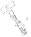
- Figs. 11 through 15 show a second embodiment of the contact 2 comprising a contact positioner 11 and a contact spring 12.
- the guide face 10 in the second embodiment is not integrally formed as part of the contact spring, but is integrally formed as part of the contact positioner 11.
- Fig. 12 shows the second embodiment of the contact positioner 11 having the guide face 10.
- the guide face 10 is integrally formed with the first lateral face 34.
- the first lateral face 34 is integrally formed with a transverse web 56.
- the transverse web 56 is guided from the first lateral face 34 transversely via the receiving space up to the opposing second lateral face 48 and rests on the second lateral face 48.
- the guide face 10 extends in the longitudinal direction of the contact positioner 11 in the direction of the first cover 19 and is integrally connected to the second lateral face 48.
- the second lateral face 48 has a guide plate 28.
- the upper edge of the guide plate 28 is formed to correspond with the bulging shape of the guide plate 10.
- the upper edge of the first cover 19 is also preferably arranged at the same height as the upper edge of the end region of the guide face 10 associated with the first cover 19.
- the lower lateral face 51 projects beyond the first and second lateral faces 34, 48.
- the first and second lateral faces 34, 48 have support edges 52 and connecting faces 53 arranged at the front.
- Fig. 13 shows the second embodiment of the contact spring 12, which has substantially the same form as the contact spring 12 shown in Fig. 5.
- the contact spring 12 has a shortened first surface region 27 and does not have a guide face 10.
- the frame 39 has inner connecting faces 54 positioned at the two opposing lateral frame portions.
- the first surface region 27 tapers in the direction of the contact positioner 11.
- the first surface region 27 is inserted laterally between the bearing edges 52 of the first and second lateral faces 34, 43.
- the frame 39 rests with its lower side on the lower lateral face 51.
- the inner connecting faces 54 rest on the connecting faces 53 of the receiving housing 50.
- a simplified weld joint is therefore possible.
- the contact spring and the contact positioner are welded to one another via weld points 55, the weld points being arranged in the region of the frame 39.
- the receiving housing 50 of the contact positioner 11 is also kept in its shape via a weld point 55.
- the weld point 55 is provided between the second surface region 33 and the second lateral face 48.
- the weld joint is preferably produced by laser welding.
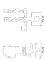
- Fig. 14 shows a blank of the second embodiment of the contact positioner 11 of Fig. 12 in which the second contact positioner 11 is cut, punched or stamped from a plate.
- Fig. 15 shows a blank of the second contact spring 12 of Fig. 13 in which the contact spring 12 is cut, punched or stamped from a plate.
- the contact positioner 11 and the contact spring 12 are produced from the blanks by appropriate bending and/or curving processes.
- a considerable advantage of the contact according to the first and second embodiments of the invention is that a cover is associated with the locking element in the direction of withdraw, and prevents contact of an edge region of the locking element, arranged on the locking side, with a seal.
- a locking element with a surface which is as closed as possible is therefore obtained.
- the surface of the locking element is preferably completely closed. This ensures that when the contact is pushed out of the housing the seal is raised by the cover and consequently damage to the seal by the edge region of the locking element is reliably avoided.
Landscapes
- Connector Housings Or Holding Contact Members (AREA)
Abstract
Description
Claims (10)
- A contact (2) having a termination section (21) for the connection of an electrical conductor, a contact section (26) for contacting a complementary contact, a locking element (5) with a guide face (10) having a locking side (13) for locking the contact (2) in a housing (1), characterised in that the locking element (5) has a cover (19) that covers the locking side (13) to form a closed surface.
- Contact according to claim 1, characterised in that the guide face (10) has a lateral side in respect to the locking side (13) having a guide plate (28) that covers the lateral side of the guide face (10).
- Contact according to claim 2, characterised in that the cover (19) is integrally formed with the guide plate (28).
- Contact according to any one of claims 1 to 3, characterised in that contact arms (40) are arranged in the contact section, and a stop element (44) is limits bending of the contact arms (40) to a maximum value.
- Contact according to any one of claims 1 to 4, characterised in that a support (36, 41) is arranged below the guide face (10) and supports the guide face (10) at a fixed height.
- Contact according to any one of claims 1 to 5, characterised in that the cover (19) has a rounded upper edge.
- Contact according to any one of claims 1 to 6, characterised in that the contact section (26) is covered by a plate (33) that forms an edge between the contact section (26) and the termination section (21), the edge (33) covered with a second cover (20).
- Contact according to any one of claims 1 to 7, characterized in that the contact (2) comprises a contact positioner (11) and a contact spring (12).
- Contact according to claim 8, characterised in that the contact positioner (11) and the contact spring (12) are formed from stamping and bending a plate.
- Contact according to claims 8 or 9, characterized in that the contact spring (12) has a frame (39) rigidly connected to the contact positioner (11) by welding.
Priority Applications (1)
| Application Number | Priority Date | Filing Date | Title |
|---|---|---|---|
| EP02018121A EP1289071B1 (en) | 2001-08-30 | 2002-08-14 | Contact with an improved locking element |
Applications Claiming Priority (3)
| Application Number | Priority Date | Filing Date | Title |
|---|---|---|---|
| EP01120857 | 2001-08-30 | ||
| EP01120857 | 2001-08-30 | ||
| EP02018121A EP1289071B1 (en) | 2001-08-30 | 2002-08-14 | Contact with an improved locking element |
Publications (3)
| Publication Number | Publication Date |
|---|---|
| EP1289071A2 true EP1289071A2 (en) | 2003-03-05 |
| EP1289071A3 EP1289071A3 (en) | 2004-04-21 |
| EP1289071B1 EP1289071B1 (en) | 2006-12-13 |
Family
ID=26076701
Family Applications (1)
| Application Number | Title | Priority Date | Filing Date |
|---|---|---|---|
| EP02018121A Expired - Lifetime EP1289071B1 (en) | 2001-08-30 | 2002-08-14 | Contact with an improved locking element |
Country Status (1)
| Country | Link |
|---|---|
| EP (1) | EP1289071B1 (en) |
Cited By (6)
| Publication number | Priority date | Publication date | Assignee | Title |
|---|---|---|---|---|
| EP1463155A1 (en) * | 2003-03-14 | 2004-09-29 | Japan Aviation Electronics Industry Limited | Connector in which a locking portion to be engaged with a housing is formed inside a contact |
| WO2007017560A1 (en) * | 2005-08-09 | 2007-02-15 | Fci | Connector sealing device |
| DE102005051724A1 (en) * | 2005-10-27 | 2007-05-03 | Yazaki Europe Ltd., Hemel Hempstead | Electric contact |
| EP1990869A1 (en) * | 2007-05-08 | 2008-11-12 | Sumitomo Wiring Systems, Ltd. | A connector and assembling method thereof |
| KR100910682B1 (en) * | 2001-08-30 | 2009-08-04 | 타이코 일렉트로닉스 에이엠피 게엠베하 | Contact with an improved locking element |
| WO2016030129A1 (en) * | 2014-08-25 | 2016-03-03 | Robert Bosch Gmbh | Contact element |
Families Citing this family (1)
| Publication number | Priority date | Publication date | Assignee | Title |
|---|---|---|---|---|
| JP7803879B2 (en) * | 2020-12-04 | 2026-01-21 | 古河電気工業株式会社 | Female terminals, connectors, bus bars, wires with terminals, wires with connectors and wire harnesses |
Family Cites Families (5)
| Publication number | Priority date | Publication date | Assignee | Title |
|---|---|---|---|---|
| JP3119418B2 (en) * | 1994-04-20 | 2000-12-18 | 矢崎総業株式会社 | Terminal for waterproof connector |
| JPH0850947A (en) * | 1994-08-04 | 1996-02-20 | Yazaki Corp | Connector for round terminals |
| US5997363A (en) * | 1996-12-18 | 1999-12-07 | The Whitaker Corporation | Single piece electrical terminal for sealed connectors |
| JP3494857B2 (en) * | 1997-08-08 | 2004-02-09 | 矢崎総業株式会社 | Connecting terminal |
| DE20013570U1 (en) * | 2000-08-08 | 2001-01-11 | Leopold Kostal GmbH & Co KG, 58507 Lüdenscheid | Contact element for plug connections |
-
2002
- 2002-08-14 EP EP02018121A patent/EP1289071B1/en not_active Expired - Lifetime
Cited By (13)
| Publication number | Priority date | Publication date | Assignee | Title |
|---|---|---|---|---|
| KR100910682B1 (en) * | 2001-08-30 | 2009-08-04 | 타이코 일렉트로닉스 에이엠피 게엠베하 | Contact with an improved locking element |
| US6869312B2 (en) | 2003-03-14 | 2005-03-22 | Japan Aviation Electronics Industry, Limited | Connector in which a locking portion to be engaged with a housing is formed inside a contact |
| EP1463155A1 (en) * | 2003-03-14 | 2004-09-29 | Japan Aviation Electronics Industry Limited | Connector in which a locking portion to be engaged with a housing is formed inside a contact |
| WO2007017560A1 (en) * | 2005-08-09 | 2007-02-15 | Fci | Connector sealing device |
| DE102005051724A1 (en) * | 2005-10-27 | 2007-05-03 | Yazaki Europe Ltd., Hemel Hempstead | Electric contact |
| DE102005051724B4 (en) * | 2005-10-27 | 2007-10-25 | Yazaki Europe Ltd., Hemel Hempstead | Electric contact |
| US7300319B2 (en) | 2005-10-27 | 2007-11-27 | Yazaki Europe Ltd. | Electrical contact |
| EP1990869A1 (en) * | 2007-05-08 | 2008-11-12 | Sumitomo Wiring Systems, Ltd. | A connector and assembling method thereof |
| US7476133B2 (en) | 2007-05-08 | 2009-01-13 | Sumitomo Wiring Systems, Ltd. | Connector |
| WO2016030129A1 (en) * | 2014-08-25 | 2016-03-03 | Robert Bosch Gmbh | Contact element |
| CN106663891A (en) * | 2014-08-25 | 2017-05-10 | 罗伯特·博世有限公司 | Contact element |
| US9859644B2 (en) | 2014-08-25 | 2018-01-02 | Robert Bosch Gmbh | Contact element |
| CN106663891B (en) * | 2014-08-25 | 2019-04-30 | 罗伯特·博世有限公司 | contact element |
Also Published As
| Publication number | Publication date |
|---|---|
| EP1289071A3 (en) | 2004-04-21 |
| EP1289071B1 (en) | 2006-12-13 |
Similar Documents
| Publication | Publication Date | Title |
|---|---|---|
| US6672910B2 (en) | Contact with an improved locking element | |
| EP1890363B1 (en) | A female terminal fitting | |
| JP2615161B2 (en) | Contact frame for IC card reader | |
| EP1162698B1 (en) | Female terminal fitting | |
| US20020077000A1 (en) | Female terminal | |
| JP2007035291A (en) | Electrical connector | |
| US5112254A (en) | Electrical contacts | |
| CN101645544A (en) | A terminal fitting and a method of forming it | |
| CN101645542A (en) | A terminal fitting and a crimping method | |
| EP1289071A2 (en) | Contact with an improved locking element | |
| JP2603930Y2 (en) | Female terminal fitting | |
| EP2704268B1 (en) | Connector terminal | |
| JP2900210B2 (en) | ID terminal | |
| JPH09232021A (en) | Female electric terminal | |
| JP2005228710A (en) | Press-fit terminal and method for manufacturing press-fit terminal | |
| KR102949175B1 (en) | A plug equipped with a guide plate | |
| JP2023034689A (en) | socket connector | |
| JPH0735316Y2 (en) | Receptacle type contact | |
| US5591044A (en) | Press-connecting terminal | |
| EP0938758A1 (en) | Electrical contact | |
| EP0958638B1 (en) | Single piece polarized electrical terminal | |
| JPH0817099B2 (en) | Surface mount type electric component and manufacturing method thereof | |
| JP2583012Y2 (en) | Connecting terminal | |
| EP1128469B1 (en) | An insulation-displacement terminal fitting and production method therefor | |
| JP3324261B2 (en) | High frequency device case |
Legal Events
| Date | Code | Title | Description |
|---|---|---|---|
| PUAI | Public reference made under article 153(3) epc to a published international application that has entered the european phase |
Free format text: ORIGINAL CODE: 0009012 |
|
| AK | Designated contracting states |
Kind code of ref document: A2 Designated state(s): AT BE BG CH CY CZ DE DK EE ES FI FR GB GR IE IT LI LU MC NL PT SE SK TR |
|
| AX | Request for extension of the european patent |
Extension state: AL LT LV MK RO SI |
|
| PUAL | Search report despatched |
Free format text: ORIGINAL CODE: 0009013 |
|
| AK | Designated contracting states |
Kind code of ref document: A3 Designated state(s): AT BE BG CH CY CZ DE DK EE ES FI FR GB GR IE IT LI LU MC NL PT SE SK TR |
|
| AX | Request for extension of the european patent |
Extension state: AL LT LV MK RO SI |
|
| 17P | Request for examination filed |
Effective date: 20040924 |
|
| 17Q | First examination report despatched |
Effective date: 20041025 |
|
| AKX | Designation fees paid |
Designated state(s): DE FR GB IT |
|
| GRAP | Despatch of communication of intention to grant a patent |
Free format text: ORIGINAL CODE: EPIDOSNIGR1 |
|
| GRAS | Grant fee paid |
Free format text: ORIGINAL CODE: EPIDOSNIGR3 |
|
| GRAA | (expected) grant |
Free format text: ORIGINAL CODE: 0009210 |
|
| AK | Designated contracting states |
Kind code of ref document: B1 Designated state(s): DE FR GB IT |
|
| REG | Reference to a national code |
Ref country code: GB Ref legal event code: FG4D |
|
| REF | Corresponds to: |
Ref document number: 60216679 Country of ref document: DE Date of ref document: 20070125 Kind code of ref document: P |
|
| ET | Fr: translation filed | ||
| PLBE | No opposition filed within time limit |
Free format text: ORIGINAL CODE: 0009261 |
|
| STAA | Information on the status of an ep patent application or granted ep patent |
Free format text: STATUS: NO OPPOSITION FILED WITHIN TIME LIMIT |
|
| 26N | No opposition filed |
Effective date: 20070914 |
|
| REG | Reference to a national code |
Ref country code: DE Ref legal event code: R082 Ref document number: 60216679 Country of ref document: DE Representative=s name: WILHELM & BECK, DE Ref country code: DE Ref legal event code: R081 Ref document number: 60216679 Country of ref document: DE Owner name: TE CONNECTIVITY GERMANY GMBH, DE Free format text: FORMER OWNER: TYCO ELECTRONICS AMP GMBH, 64625 BENSHEIM, DE |
|
| REG | Reference to a national code |
Ref country code: FR Ref legal event code: PLFP Year of fee payment: 14 |
|
| REG | Reference to a national code |
Ref country code: FR Ref legal event code: CD Owner name: TE CONNECTIVITY GERMANY GMBH Effective date: 20151027 |
|
| REG | Reference to a national code |
Ref country code: FR Ref legal event code: PLFP Year of fee payment: 15 |
|
| REG | Reference to a national code |
Ref country code: FR Ref legal event code: PLFP Year of fee payment: 16 |
|
| REG | Reference to a national code |
Ref country code: FR Ref legal event code: PLFP Year of fee payment: 17 |
|
| PGFP | Annual fee paid to national office [announced via postgrant information from national office to epo] |
Ref country code: FR Payment date: 20180712 Year of fee payment: 17 Ref country code: IT Payment date: 20180823 Year of fee payment: 17 Ref country code: DE Payment date: 20180731 Year of fee payment: 17 |
|
| PGFP | Annual fee paid to national office [announced via postgrant information from national office to epo] |
Ref country code: GB Payment date: 20180808 Year of fee payment: 17 |
|
| REG | Reference to a national code |
Ref country code: DE Ref legal event code: R119 Ref document number: 60216679 Country of ref document: DE |
|
| GBPC | Gb: european patent ceased through non-payment of renewal fee |
Effective date: 20190814 |
|
| PG25 | Lapsed in a contracting state [announced via postgrant information from national office to epo] |
Ref country code: FR Free format text: LAPSE BECAUSE OF NON-PAYMENT OF DUE FEES Effective date: 20190831 Ref country code: DE Free format text: LAPSE BECAUSE OF NON-PAYMENT OF DUE FEES Effective date: 20200303 |
|
| PG25 | Lapsed in a contracting state [announced via postgrant information from national office to epo] |
Ref country code: GB Free format text: LAPSE BECAUSE OF NON-PAYMENT OF DUE FEES Effective date: 20190814 Ref country code: IT Free format text: LAPSE BECAUSE OF NON-PAYMENT OF DUE FEES Effective date: 20190814 |