BACKGROUND OF THE INVENTION
Technical Field of the Invention
The present invention relates to an optical disk
which is irradiated with a laser beam to thereby record
information, an optical disk recording apparatus which
irradiates the optical disk with the laser beam and records
information, and a control method and control program of the
recording apparatus.
Related Art
As portable recording mediums for recording a large
volume of data, recordable optical disks such as a compact
disc-recordable (CD-R) and CD-rewritable (CD-RW) are used,
and these optical disks comply with provisions of Orange Book
as written standards of the recordable optical disk.
Additionally, for disk drive apparatuses of
recording information in an optical disk, such as a DC-R
drive, there is much demand for increasing of a recording
speed. However, the use of the optical disk in accordance
with the current standard is a factor for hindering the speed
from increasing, and the change of the standard of the
optical disk is sometimes required in order to realize the
increasing of the recording speed.
However, when the standards of the optical disk such
as CD-R are changed as described above, and the information
is recorded in the CD-R manufactured in accordance with a new
standard by the CD-R drive designed in accordance with an old
standard, an appropriate recording of information cannot be
performed with high possibility because of alteration an
information write strategy due to the change of the standards.
Therefore, when the CD-R conforming to new standards is
irradiated with a laser beam and the recording is performed
by the CD-R drive conforming to the old standards, the
recording may appear successful to a user of the drive, but
in actual the appropriate recording may not be performed due
to discrepancy between the old and new standards. Such a CD-R
possibly creates a trouble and fails to reproduce the
recorded information, even though the recording has been
performed without trouble problem.
SUMMARY OF THE INVENTION
The present invention has been developed in
consideration of the above-described circumstances, and an
object thereof is to provide an optical disk capable of
inhibiting an inappropriate recording from being performed by
a recording apparatus conforming to old standards, an optical
disk recording apparatus capable of appropriately recording
information in optical disks conforming to either of new and
old standards, and a control method and control program of
such a recording apparatus.
To solve the problem, according to the present
invention, there is provided an optical disk having a
circular shape formed with a pregroove along a
circumferential direction of the circular shape. The
inventive optical disk is compatible with one type of a
recording apparatus which is designed to irradiate an optical
beam onto the optical disk to form pits along the pregroove
for actual recording of information. The inventive optical
disk is incompatible with another type of a recording
apparatus which is designed to conduct test recording before
actual recording on a test area of a conventional optical
disk repeatedly up to a predetermined number of times and
which is designed to successively record the times of the
test recording into a count area of the conventional optical
disk such that the final time may be recorded in a
predetermined section of the count area. The inventive
optical disk has a test area corresponding to the test area
of the conventional optical disk and a prepit area
corresponding to the count area of the conventional optical
disk, the prepit area being provisionally formed with prepits
at least in a section corresponding to the predetermined
section of the count area of the conventional optical disk so
as to inhibit said another type of the recording apparatus
from conducting the test recording.
According to the inventive constitution, when the
inventive optical disk is set in a conventional recording
apparatus for performing the test recording with respect to
the optical disk defined by a new standard, the predetermined
section of the count area corresponding to the maximum number
of the test times is filled with the prepits as dummy count
information, and the recording apparatus judges from the
dummy information that the test recording cannot be performed
any more. Therefore, the inappropriate recording can be
prevented from being performed by the conventional recording
apparatus conforming to an old standard.
Moreover, according to the present invention, there
is provided an apparatus constructed for performing an actual
recording of information by irradiating an optical beam onto
an optical disk which may be manufactured according to either
of a first standard and a second standard different from the
first standard, and constructed for performing a test
recording before the actual recording so as to determine an
optimal power of the optical beam which may vary between the
first standard and the second standard. The inventive
apparatus comprises a detecting section that detects whether
the optical disk is manufactured according to the first
standard or the second standard, a first control section that
executes the test recording in accordance with the first
standard to determine the optimal valve of the optical beam
under the first standard, a second control section that
executes the test recording in accordance with the second
standard to determine the optimal value of the optical beam
under the second standard, and a selecting section that
selectively activates the first control section when the
first standard is detected from the optical disk and
otherwise selectively activates the second control section
when the second standard is detected from optical disk.
Furthermore, according to the present invention,
there is provided a method of operating an apparatus
constructed for performing an actual recording of information
by irradiating an optical beam onto an optical disk which may
be manufactured according to either of a first standard and a
second standard different from the first standard, and
constructed for performing a test recording before the actual
recording so as to determine an optimal power of the optical
beam which may vary between the first standard and the second
standard. The inventive method is carried out by the steps
of detecting whether the optical disk is manufactured
according to the first standard or the second standard,
executing the test recording in accordance with the first
standard to determine the optimal valve of the optical beam
under the first standard when the first standard is detected
from the optical disk, and executing the test recording in
accordance with the second standard to determine the optimal
value of the optical beam under the second standard when the
second standard is detected from optical disk.
Additionally, according to the present invention,
there is provided a computer program for use in an optical
recording apparatus designed for performing an actual
recording of information by irradiating an optical beam onto
an optical disk which may be manufactured according to either
of a first standard and a second standard different from the
first standard, and designed for performing a test recording
before the actual recording so as to determine an optimal
power of the optical beam which may vary between the first
standard and the second standard. The inventive computer
program is executable by a processor equipped in the optical
recording apparatus for carrying out a control process
comprising the steps of detecting whether the optical disk is
manufactured according to the first standard or the second
standard, conducting the test recording in accordance with
the first standard to determine the optimal valve of the
optical beam under the first standard when the first standard
is detected from the optical disk, and conducting the test
recording in accordance with the second standard to determine
the optimal value of the optical beam under the second
standard when the second standard is detected from optical
disk.
According to the above-described inventive apparatus,
the method and the computer program, it is judged whether the
optical disk set in the optical disk recording apparatus
conforms to the first standard or the second standard, and
the appropriate test recording can be performed according to
the judgement. Therefore, the performing of the
inappropriate test recording in accordance with the standard
different from that of the set optical disk can be inhibited,
and the inappropriate recording can be prevented beforehand
from being performed with respect to the optical disk.
BRIEF DESCRIPTION OF THE DRAWINGS
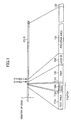
FIG. 1 is a diametric sectional view of an optical
disk showing area divisions of CD-R according to a first
standard.
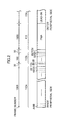
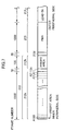
FIG. 2 is a diagram schematically showing an area
constitution of PCA in the CD-R according to the first
standard.
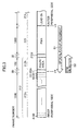
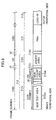
FIG. 3 is a diagram schematically showing an area
constitution of a PCA in a CD-R according to a first
embodiment of the present invention, which conforms to a
standard different from the first standard.
FIG. 4 is an explanatory view showing a processing
to be executed by a CD-R drive for performing an appropriate
recording with respect to the CD-R according to the first
embodiment.
FIG. 5 is an explanatory view of a method of
performing the appropriate recording in a case where the CD-R
of the different standard is set in the CD-R drive.
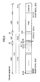
FIG. 6 is a diagram schematically showing the area
constitution of the PCA in a modification example of the CD-R
according to the first embodiment.
FIG. 7 is a diagram schematically showing the area
constitution of the PCA in another modification example of
the CD-R according to the first embodiment.
FIG. 8 is a diagram schematically showing the area
constitution of the PCA in another modification example of
the CD-R according to the first embodiment.
FIG. 9 is a diagram schematically showing the area
constitution of the PCA of a CD-RW in a case where the
present invention is applied to the CD-RW.
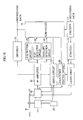
FIG. 10 is a block diagram showing a constitution of
an optical disk recording apparatus according to a second
embodiment of the present invention.
FIG. 11 is a flowchart showing a processing executed
by a controller of the optical disk recording apparatus
according to the second embodiment during the recording.
DETAILED DESCRIPTION OF THE INVENTION
Embodiments of the present invention will be
described hereinafter with reference to the drawings.
A. First Embodiment
A-1. CD-R according to First Standard, and OPC Processing
with respect to the CD-R
First, prior to the description of a CD-R according
to a first embodiment of the present invention, a CD-R
prepared in accordance with a standard of Orange Book which
is current at the time of filing the present application
(Orange Book, Part III: CD-RW, Vol. 2: High Speed, Version
1.0; hereinafter referred to as a first standard) will be
described. To record information in the CD-R conforming to
the first standard, a CD-R drive obtains an optimum laser
power for the recording into the CD-R, and performs the
recording with the obtained laser power. That is, in the CD-R
drive, a laser power optimization processing of obtaining
an optimum laser power (hereinafter referred to as OPC:
Optimum Power Control) is performed prior to the real
recording. A detailed method of the OPC is defined in the
above-described Orange Book as the standard of a recordable
optical disk. In the following, a recording area of the CD-R
according to Orange Book will first be described with
reference to FIG. 1, and thereafter a processing by the CD-R
drive in executing the OPC with respect to the CD-R will be
described.
As shown in the drawing, for the CD-R, a section
having a diameter of 46 to 50 mm is prepared as a lead-in
area 114, and a program area 118 and residual area 120 for
recording data are prepared on an outer peripheral side of
the lead-in area. On the other hand, a program memory area
(PMA) 115 is prepared in an inner peripheral side of the
lead-in area 114, and a power calibration area (PCA) 112 is
prepared on a further inner peripheral side.
A test area 112a, count area 112b, and spare areas
112c, 112d are prepared in the PCA 112. In the test area
112a, a test recording is performed prior to the real
recording processing. Here, an area in which the test
recording can be performed 100 times at most is prepared as
the test area 112a, and an area for recording up to 100
pieces of eight-to-fourteen modulation (EFM) signals
indicating a range of the test area 112a in which the test
recording has been already performed is prepared in the count
area 112b.
Here, FIG. 2 is a diagram showing a further detailed
area structure of the PCA 112. As shown in the drawing, an
area of 1500 frames is prepared on an innermost peripheral
side of the CD-R as the test area 112a, and data is recorded
in the area of 15 frames at one test recording by the CD-R
drive. Here, among sections obtained by dividing the test
area 112a every 15 frames, a first test recording is
performed into an area A1 on an outermost peripheral side, a
second test recording is performed with respect to an area A2
inwardly next to the area A2, and a third test recording is
performed with respect to an area A3 located on the further
inner peripheral side. Thereafter, the test recording is
similarly performed with respect to each area of 15 frames on
the inner peripheral side, and the last 100-th test recording
is performed with respect to an area A100 of 15 frames
located on the innermost peripheral side of the PCA 112.
The spare area 112c of 30 frames is prepared on the
outer peripheral side of the test area 112a in the PCA 112.
The count area 112b of 100 frames is prepared on the further
outer peripheral side of the spare area 112c. When the first
test recording ends by the CD-R drive, the EFM signal is
written in a frame B1 on an outermost peripheral side of the
count area 112b. After the second test recording ends, the
EFM signal is written in a frame B2 inwardly next to the
frame B1. After the third test recording ends, the EFM
signal is written in a frame B3 positioned on the further
inner peripheral side. Thereafter, every time the test
recording is performed, the EFM signal is similarly written
in each frame on the inner peripheral side. After the last
100-th test recording ends, the EFM signal is written in a
frame B100 on the innermost peripheral side to thereby
indicated that the test area is used up.
The spare area 112d of 30 frames is prepared on the
further outer peripheral side of the count area 112b, and the
PMA 115 is prepared on the outer peripheral side of the spare
area 112d. The PMA 115 is used as a working area for
recording information on a track in which data has been
recorded, after the end of the recording of the information
by the CD-R drive. An area of 1000 frames is the PMA 115,
and the lead-in area 114 is prepared on the outer peripheral
side. That is, the frame of the count area 112b in which the
EFM signal is to be written after the end of 100 test
recordings is positioned on the inner peripheral side spaced
by 1130 frames from a start position of the lead-in area 114.
The position of the test area 112a to start the final 100-th
test recording is on the inner peripheral side spaced by 2660
frames from the start position of the lead-in area 114.
In the OPC processing prior to the real recording,
the CD-R drive uses the PCA 112 in the CD-R with the above-described
areas prepared therein to perform the test
recording, and measures asymmetry of the reproduced signal in
order to obtain an optimum value of the laser power. In the
OPC processing, the CD-R drive controls an irradiation
position of a laser beam emitted from an optical pickup
(hereinafter referred to as the irradiation position), and
initially seeks the position of the count area 112b on the
innermost peripheral side as a target position. To move the
irradiation position to the target position (here, the
position of the count area 112b on the innermost peripheral
side) in the CD-R drive, a control is executed which
comprises: moving the irradiation position slightly toward
the inner peripheral side from the target position; moving
the irradiation position toward the outer peripheral side
while reading the information recorded in the CD-R; and using
the information to detect the target position. Here,
information used in the seeking to the target position by the
CD-R drive is absolute time information (= absolute position
information) involved in pregroove (ATIP) information which
can be obtained from a wobble signal extractible from a
reflected light from a pregroove formed in the CD-R. For the
absolute time information of the ATIP information, the start
position of the lead-in area 114 is set to 0, and a position
on the inner peripheral side of the position by 1130 frames
is the innermost peripheral position of the count area 112b.
Therefore, the CD-R drive judges the position in which the
absolute time information indicating the span of 1130 frames
is obtained as the innermost peripheral position of the count
area 112b, and executes a position control. Moreover, the
ATIP information is also used in adjusting the positions of
the optical pickup such as the start position of each area
described hereinafter. Furthermore, the seeking is started
from the position on the inner peripheral side slightly from
the target position, so that the target position is more
accurately detected. In more detail, a runup section for
synchronization with the ATIP information until the target
position is sought is provided. Additionally, the ATIP is a
known technique defined in Orange Book, and therefore
detailed description thereof is omitted.
As described above, to move the irradiation position
to the certain target position (here the innermost peripheral
position of the count area 112b), the CD-R drive executes a
control to start the seeking from the position on the inner
peripheral side slightly shifted from the target position,
the moves the irradiation position toward the outer
peripheral side and detects the target position. Therefore,
in the seeking where the innermost peripheral position of the
count area 112b is the target position, the seeking is
started toward the outer peripheral side from the frame on
the innermost peripheral side of the count area 112b, that is,
from the position on the inner peripheral side slightly (e.g.,
by 20 to 30 frames) shifted from the frame B100 in which the
EFM signal is written after the end of the 100-th recording.
After the CD-R drive starts the seeking from the
position on the inner peripheral side slightly shifted from
the frame B100 as described above, it is detected whether or
not the EFM signal is written in the frame B100. When the
signal is written, the CD-R has been already performed with
100 test recordings therein, and the test recording cannot be
performed any more. Therefore, the CD-R drive executes an
error processing, and informs a user that the CD-R reaches
the end of life. On the other hand, when the EFM signal is
not written in the frame B100, it is judged whether or not
the EFM signal is written in the next frame on the outer
peripheral side of the frame B100. When the EFM signal is
not written in the next frame, the judgment is performed with
respect to a further outer-peripheral frame. For the count
area 112b, the irradiation position is successively moved to
the outer peripheral frames in this manner until the frame
with the EFM signal written therein is detected. It is thus
detected whether or not the EFM signal is written in each
frame.
When it is detected that the EFM signal is written
in a frame other than the frame B100, the frame then
indicates the number of test recordings already performed
with respect to the CD-R, and therefore, the CD-R drive
starts the seeking while the position of the area to be
subjected to the test recording next to the number of test
recordings corresponding to the number of frames detected in
the count area 112b is regarded as the target position. Also
during this seeking, the irradiation position is moved to the
position on the inner peripheral side slightly shifted from
the target position similarly as described above. For
example, when it is detected that the EFM signal is written
in the 30-th frame after the 30-th test recording is
performed in the count area 112b, the CD-R drive then moves
the irradiation position to the position on the inner
peripheral side slightly deviated from the position of the
area in which the 31-st test recording is to be performed in
the test area 112a.
The CD-R drive performs the seeking toward the outer
peripheral side from the slightly inner peripheral position,
thereby detects the area to be subjected to the current test
recording, and then performs the test recording with respect
to the area. In the test recording performed here, the
recording laser power value is changed in 15 stages, the EFM
signal for one sub code frame is recorded per one recording
laser power value, and the EFM signals for 15 frames in total
are recorded. After ending the test recording in this manner,
obtaining the reproduced signal from the test-recorded area
and determining the optimum recording laser power value, the
CD-R drive moves the optical pickup, writes an EFM signal in
the next frame on the inner peripheral side of the frame with
the EFM signal detected therefrom in the count area 112b, and
ends the OPC. For example, when the 31-st test recording is
performed, the EFM signal is written in a 31-st frame counted
from the outer peripheral side of the count area 112b.
Additionally, when the EFM signal is not written in
the frame B1 of the above-described count area 112b, that is,
the EFM signal is not written in any frame of the count area
112b, the test recording has never been performed in the CD-R,
and therefore the test recording is performed with respect to
the first area A1 to be subjected to the first test recording
in the test area 112a.
The above is a detail of the OPC performed by the
CD-R drive with respect to each area involved in the PCA 112
of the CD-R conforming to Orange Book (first standard)
current at the time of filing of present application.
A-2. CD-R according to the First Embodiment
The CD-R according to the present embodiment will
next be described. The CD-R according to the present
embodiment is a CD-R manufactured in accordance with a
standard different from the above-described standard
(hereinafter referred to as a second standard for the sake of
convenience). When the new CD-R conforming to the second
standard is used, and the new CD-R is set in the conventional
CD-R drive for executing an appropriate OPC processing with
respect to the old CD-R with the above-described areas set
therein and a recording processing is performed according to
the first standard, the recording seems successful to a user.
However in actual, an appropriate recording is not performed,
and a problem that the recorded CD-R cannot be reproduced
sometimes occurs. The invention is directed to resolve the
problem. Namely, when the inventive CD-R according to the
present embodiment is set in the conventional CD-R drive
designed for performing the recording processing including
the OPC with respect to the old CD-R conforming to the first
standard, the inventive new CD-R according to the present
embodiment uses an area constitution for preventing the
conventional CD-R drive from recording the data. The
constitution of the new CD-R according to the present
embodiment in which the recording processing is prohibited
from being performed by the old CD-R drive having a different
standard will be described hereinafter with reference to FIG.
3. Additionally, since the program area and the outer
peripheral area have an area constitution similar to that of
the old CD-R conforming to the first standard, the
description thereof is omitted.
As shown in the drawing, in a new CD-R 100 according
to the present embodiment, a PCA 212 is prepared on the inner
peripheral side, a PMA 215, lead-in area 214, program area
(not shown) and residual area are prepared on the outer
peripheral side, and the number of frames of the area on the
outer peripheral side of the PCA 212 and the start position
of each area are similar to those of the old CD-R (see FIGS.
1 and 2) conforming to the above-described first standard.
That is, an area of 1660 frames extending from the position
on the inner peripheral side spaced from the start position
of the lead-in area 214 by 2660 frames is the PCA 212, and an
area of 1000 frames extending from the position on the inner
peripheral side from the start position of the lead-in area
214 by 1000 frames is the PMA 215.
In the second standard, the PMA 215 is used as the
working area for the recording process similarly as the
above-described old CD-R conforming to the first standard.
Similarly as the first standard, the lead-in area 214 is an
area where a table of contents (TOC) is written after the end
of the recording of the program area. Moreover, as the ATIP
information of this area, the time of the program area, time
of lead-in area, start time of the lead-in area, start
possible time of a maximum lead-out (LLO: Last Possible Start
Time of Lead-Out), special information and the like are
recorded. In the new CD-R conforming to the second standard,
as special information of the ATIP information, standard
identification information indicating that the CD-R is
manufactured in accordance with the second standard is
prerecorded.
In the new CD-R according to the present embodiment,
as the PCA 212, a test area 212a, spare areas 212c, 212d, and
prepit area 212b are prepared. Similarly as the old CD-R
conforming to the above-described first standard (see FIG. 2),
as the test area 212a, an area or 1500 frames extending from
the position on the inner peripheral side spaced from the
start position of the lead-in area 214 by 2660 frames is
prepared. Similarly as the first standard, the areas of 15
frames for each test recording, that is, areas A1,
A2, ...A100 for performing up to 100 times of test recording
are prepared.
The prepit area 212b is composed of 100 frames
extending from the position on the inner peripheral side
spaced from the start position of the lead-in area 214 by
1130 frames, and a prepit is formed by mastering in this area
to prerecord dummy information. That is, in the old CD-R
drive where the new CD-R is set, the prepit area of 100
frames is treated as of the EFM signal has been already
written. Here, the prepit area 212b is disposed in the same
relative position viewed from the start position of the lead-in
area as a reference of the position control of the optical
pickup as that of the count area 112b in the first standard.
The area constitution of the CD-R according to the present
embodiment has been described above.
A-3. OPC Processing with respect to CD-R according to the
First Embodiment
The OPC processing while setting the new CD-R
according to the present embodiment, that is, the CD-R
according to the second standard in the conventional CD-R
drive conforming to the first standard will next be described.
As described above, the CD-R drive conforming to the first
standard naturally performs the processing similar to the OPC
performed with respect to the old CD-R (see FIGS. 1 and 2)
conforming to the above-described first standard. That is,
to perform the OPC with respect to the CD-R conforming to the
first standard as described above, the number of the test
recording sessions performed past with respect to the CD-R is
recognized in accordance with a frame range of the count area
112b in which the EFM signal is recorded. Therefore, the CD-R
drive moves the optical pickup toward the inner peripheral
side from the start position LS of the lead-in area 214 (step
S1), and starts the seeking of tracks toward the outer
peripheral side from the position on the slightly inner
peripheral side of the count area 112b (the position on the
inner peripheral side spaced from the start position of the
count area 112b by about 20 frames). Even when the new CD-R
of the present embodiment is set in this manner, the old CD-R
drive performs the seek processing similarly as described
above, and the seeking starts from a position P1 on the inner
peripheral side slightly spaced from the prepit area 212b.
Subsequently, the CD-R drive starts the seeking from
the position P1, moves the optical pickup toward the outer
peripheral side and detects the frames of the prepit area
212b in which the EFM signals are recorded (step S2). Here,
the prepit area 212b of the CD-R conforming to the second
standard is recognized as if the count area in which the EFM
signals are recorded by the old CD-R drive. Therefore, the
conventional CD-R drive recognizes that the EFM signal is
recorded up to the innermost peripheral frame of the prepit
area 212b (the frame in the position corresponding to the
100-th count area in the first standard) due to the dummy
information provided by the prepits. Thereby, the
conventional CD-R drive judges that the 100 times of the test
recording of the CD-R end, and executes an error processing
of informing the user that the recording cannot be performed
any more. That is, the CD-R drive ends the processing
without performing the actual recording with respect to the
new CD-R according to the present embodiment.
With the use of the above-described CD-R according
to the present embodiment, even when the new CD-R is set in
the old CD-R drive designed in accordance with the first
standard as the different standard, the recording processing
can be inhibited from being executed by the old CD-R drive.
When the standard differs as described above, various
elements such as recording strategy also sometimes change.
In this case, even when the recording is apparently performed
on the CD-R drive side, the normal recording is not possibly
performed in actual in some case. Therefore, when the CD-R
according to the present embodiment is used, the recording
processing by the CD-R drive designed in accordance with the
different standard can be inhibited from being executed, and
the recording error can be prevented beforehand from being
generated because of the above-described difference of the
standard.
When the new CD-R according to the present
embodiment is used as described above, the recording
processing can be inhibited from being executed by the old
CD-R drive designed in accordance with the first standard.
However, when the new CD-R is loaded into the new drive, the
test recording needs to be performed in the test area 212a so
that the CD-R is subjected to the OPC. Thus, in the new CD-R
drive designed for performing the recording with respect to
the CD-R conforming to the second standard according to the
present embodiment, the OPC may be executed in a procedure
shown in FIG. 4.
First, similarly as described above, the start
position LS of the lead-in area 214 is specified. Moreover,
the optical pickup is moved to a position P2 on the inner
peripheral side slightly (by about 20 frames) shifted from
the test area 212a from the start position LS of the lead-in
area 214 (step Sa1).
Moreover, the CD-R drive starts the seeking toward
the outer peripheral side from the position P2, directly
accesses and reads the test area 212a, and detects the number
of sections in which the test recording is performed in the
test area 212a (step Sa2). Here, the area of 1500 frames is
prepared in the test area 212a. When the seeking is
performed at a basic speed (one second for the seeking of 75
frames), 20 seconds are necessary for reading all the test
area 212a of 1500 frames. However, in recent years, the
increasing of the seeking speed of the CD-R drive has been
realized. For example, when the seeking is performed at ten
times as the basic speed, all the test area 212a can be read
in two seconds. That is, even when the test area 212a is
directly read without using the count area 112b and the
number of test recordings already performed is detected, much
time is not required. Therefore, when the OPC is executed
with respect to the CD-R according to a second standard, the
CD-R drive uses a method of directly reading the test area
212a and detecting the number of tests already performed.
The presence/absence of the recording into the test
area 212a is read and the number of tests is detected as
described above, and the test recording is then performed in
the section (15 frames) to be subjected the test recording
next to the detected recording except for a case in which 100
test recordings are detected to have been performed. For
example, similarly as the first standard, the test recording
performed here uses a method of changing the recording laser
power value in 15 stages, and recording the EFM signals for
one sub code frame per each recording laser power value. The
CD-R drive sets an optimum recording laser power value based
on the result of the test recording, and performs the real
information recording based on the setting. Here, in the CD-R
drive, other elements concerning the recording such as the
recording strategy are also designed in accordance with the
second standard, so that an appropriate recording is
performed in the CD-R of the present embodiment.
When the CD-R according to the present embodiment is
used in this manner, and set in the CD-R drive designed in
accordance with the different first standard, the CD-R drive
is inhibited from executing the recording processing and the
inappropriate recording is prevented beforehand from being
performed. On the other hand, when the CD-R is set in the
CD-R drive designed in accordance with the second standard,
the OPC is normally executed and the appropriate recording
processing can be executed.
When the CD-R according to the present embodiment is
used as described above, the inappropriate recording because
of the difference of the standard can be prevented beforehand,
and the following method using the ATIP information is also
considered as a method of preventing the inappropriate
recording because of the difference of the standard
beforehand. That is, as shown in FIG. 5, a method is
considered using the CD-R in which the absolute time
information indicated in the ATIP information in the vicinity
of the PCA 112 is discontinuous in the spare area 112c. For
the ATIP information, an absolute time of the start position
LS of the lead-in area 114 has a reference "0:00", + absolute
time information is indicated on the outer peripheral side
from the start position of the lead-in area 114, and -
absolute time information is indicated on the inner
peripheral side. Additionally, in FIG. 5, the ordinate
indicates the absolute time information of the ATIP, and the
abscissa indicates the position of each area.
The absolute time information indicated in the ATIP
information in a middle position (the start position of the
16-th frame from the innermost peripheral side) of the above-described
spare area 112c is constituted to have a
discontinuity of 30 seconds (the position for 2250 frames).
Therefore, the absolute time information included in the ATIP
information of the start position at the 16-th frame from the
innermost peripheral side of the spare area 112c indicates a
value larger than a value of the absolute time information
indicated in the ATIP information of the start position of
the 15-th frame from the innermost peripheral side of the
spare area 112c on the inner peripheral side from the
discontinuous portion by about 30 seconds or more.
In the CD-R drive having such CD-R set therein and
designed in accordance with the first standard, when the OPC
is executed, first the optical pickup is moved and the
seeking is started toward the outer peripheral side from the
position on the inner peripheral side of the spare area 112c.
That is, the position on the inner peripheral side slightly
from the discontinuous portion of the absolute time
information of the ATIP information is a seeking start
position. Moreover, when the CD-R drive starts the seeking
toward the outer peripheral side from the position, and the
seeking position moves toward the outer peripheral side
beyond the discontinuous portion of the absolute time
information of the ATIP information, the absolute time
information increases by 30 seconds or more. Therefore,
although the CD-R drive seeks the position in the spare area
112c, it is recognized that the seeking position moves
further toward the outer peripheral side through the count
area 112b. As a result, the CD-R drive moves the optical
pickup toward the inner peripheral side and starts the
seeking from the position on the inner peripheral side of the
spare area 112c again. Thereafter, after performing the
operation of allowing the seeking position of the optical
pickup to reciprocate between the positions on the inner and
outer peripheral sides from the discontinuous portion several
times every passing through the discontinuous portion, the
error processing of informing the user that the prepit area
212b cannot be detected is performed to stop the recording
processing.
Therefore, when the CD-R having the discontinuous
portion of the absolute time information of the ATIP
information in the spare area 112c is used, similarly as the
above-described embodiment, the recording processing is
inhibited from being executed by the CD-R drive designed with
the different standard, and the inappropriate recording can
be prevented beforehand. However, this method has the
following problem.
The CD-R drive moves the optical pickup so as to set
the seeking start position to the slightly inner peripheral
position as described above, when the seeking position is
moved to the certain target position (e.g., the innermost
peripheral position of the count area 112b). This is because
the runup section is set for synchronization with the ATIP
information in order to more correctly detect the target
position. A length of this runup section is inherent in the
CD-R drive manufactured by each company, and both the CD-R
having the runup section set to be long and the CD-R having
the section set to be short are in fact distributed. Here,
when the CD-R having the discontinuous portion of the
absolute time information in the spare area 112c as described
above is set in the CD-R drive having the runup section set
to be long (e.g., having a runup period set for 200 frames),
not only the count area 112b but also the PMA 115 cannot
disadvantageously be sought. More concretely, the position
on the inner peripheral side from the innermost peripheral
(start) position by 200 frames of the runup section is the
position on the inner peripheral side from the above-described
discontinuous portion. That is, the CD-R drive
which is to seek the start position of the PMA 115 repeats
the operation of allowing the seeking position to reciprocate
between the positions on the inner and outer peripheral sides
via the discontinuous portion similarly as the operation of
seeking the above-described count area 112b as the target.
As a result, the error processing is executed. Therefore,
when the CD-R having the discontinuous portion of the
absolute time information of the ATIP information in the
above-described spare area 112c is set in the CD-R drive
having the runup section set to be long, the disadvantage
occurs.
On the other hand, the CD-R including the prepit
area 212b according to the present embodiment is not
influenced by the length of the runup section set in the CD-R
drive with the CD-R set therein, and is therefore effective
for the CD-R drive manufactured by various makers.
A-4. Modification Examples of First Embodiment
A-4-1. Modification Example 1
Additionally, in the above-described first
embodiment, the prepits are formed in all the areas of the
prepit area 212b, but, as shown in FIG. 6, the prepit may be
formed only in the innermost peripheral frame B100 (shown by
slant lines in the drawing) as the 100-th frame in the prepit
area 212b. Even when the prepit is formed only in the frame
B100, similarly as the embodiment, the CD-R drive designed in
accordance with the first standard detects that the EFM
signal is written in the frame B100 and, as a result, judges
that 100 test recordings have already been performed.
Therefore, similarly as the above-described embodiment, the
recording processing is inhibited from being executed by the
CD-R drive designed with the different standard, and the
inappropriate recording can be prevented beforehand.
A-4-2. Modification Example 2
Moreover, in the above-described embodiment, the
prepit is formed in the prepit area 212b, but additionally
the prepit may be formed in the test area 212a. For example,
as shown in FIG. 7, the prepit may be formed only in the area
A100 (shown by slant lines in the drawing) of the test area
212a in which 100 test recordings are performed. For example,
as the CD-R drive designed in accordance with the first
standard, even when the EFM signal is written in the 100-th
frame of the count area 112b, an apparatus set to perform a
processing of detecting whether or not the test recording has
been performed in actual in the test area 112a in a
confirming manner is supposedly distributed. Even with
respect to the CD-R drive set to execute the control
processing, the prepit is formed in the test area 212a, it is
judged that the test recording is not performed and the
inappropriate recording can be prevented beforehand from
being performed. Additionally, when the prepit is formed in
the area A100 of the test area 212a, the CD-R drive
conforming to the second standard may perform the seeking
toward the outer peripheral side from the area for performing
the 99-th test recording as a start point in order to detect
the number of tests already performed.
A-4-3. Modification Example 3
Moreover, in the above-described embodiment, the CD-R
drive conforming to the second standard directly seeks the
test area 212a, and detects the number of tests already
performed without using the count area. However, a new count
area may be disposed in the position other than the position
corresponding to the count area 112b in the CD-R, and the CD-R
drive may seek the new count area in order to detect the
number of tests.
For example, as shown in FIG. 8, 1370 frames (91
test recordings each for 15 frames + 5 frames) on the inner
peripheral side of the test area 212a prepared for 1500
frames in the above-described embodiment are set as a new
test area 212aa, and 100 frames from the outer peripheral
side from the test area 212a may be set as a new count area
212ab.
Moreover, in addition to the dividing of the test
area 212a of the position corresponding to the test area 112a
in the first standard into the new test area 212aa and new
count area 212ab and the setting of the new count area as
described above, a new count area may also be set on the
further inner peripheral side of the test area 212a. The new
count area may also be set to the position on the outer
peripheral side from a start possible time of a maximum lead
out (LLO: Last Possible Start Time of Lead Out) indicated in
the ATIP information by a maximum time (one minute and 30
seconds) which can be taken by the lead out. When the new
count area is set in the CD-R, the CD-R drive conforming to
the standard needs to be set to execute a processing of
detecting the number of tests using the count area newly set
by the CD-R drive conforming to the standard.
Moreover, also when the prepit is formed in the area
A100 of the test area 212a as in Modification Example 2, the
area other than the test area 212a may be divided into the
test and count areas and used.
A-4-4. Modification Example 4
Moreover, in the above-described embodiments and
modification examples, the CD-R to which the present
invention is applied has been described, but the present
invention can broadly be applied to the optical disks such as
a CD-RW conforming to the standard in which the count area
for detecting the number of tests already performed is set.
Additionally, when the present invention is applied
to the CD-RW and the prepit is formed only in the prepit area
212b as described in the above-described embodiments and
modification examples, the disadvantage sometimes occurs
depending on an OPC processing content set to be performed by
the CD-RW drive. That is, when the EFM signals are written
in all the count area 112b, the CD-RW drive conforming to the
first standard and general in the filing time of the present
application erases (DC ERASE) the EFM signals recorded in the
count area 112b and test area 112a, uses the test area 112a
and count area 112b with the EFM signals erased therefrom
again and executes the OPC.
Therefore, when the prepit is formed in the prepit
area 212b as described above, the CD-RW drive executes an
erasing processing with respect to the prepit area 212b, and
subsequently executes the recording processing with respect
to the area A1 of the test area 212a to be subjected to the
first test recording (the erasing is impossible because of
the prepit). Here, after the executing the erasing
processing with respect to the prepit area 212b, the CD-RW
drive is set to execute the error processing of detecting
whether or not the erasing is successful and informing the
user of failure when the erasing is not successful. In this
case, the recording processing can be inhibited from being
continued by the CD-RW drive. However, a certain apparatus
type is set to execute the recording processing with respect
to the area A1 to be subjected to the first test recording in
the test area 212a as such without detecting whether or not
the erasing processing is successful with respect to the
prepit area 212b, and this type of apparatus is presented to
the user in actual. When the CD-RW with the prepit formed in
the prepit area 212b is set in the CD-RW drive set as
described above, the error cannot be generated during the OPC
processing, and the inappropriate recording processing not
meeting the second standard is executed as such.
To solve the problem, when the present invention is
applied to the CD-RW, as shown in FIG. 9, the prepit is
formed in the prepit area 212b similarly as the above-described
embodiments and modification examples, and the
discontinuous portion of the absolute time information of the
ATIP information may be disposed in the innermost peripheral
position of the test area 212a or the inner peripheral
position slightly from the test area 212a. Additionally, in
FIG. 9, the ordinate indicates the absolute time information
of the ATIP, and the abscissa indicates the position of each
area.
In the shown example, the absolute time information
indicated by the ATIP information in the innermost peripheral
position of the test area 212a has a discontinuous portion
with a difference of 30 seconds (the position for 2250
frames) from the previous absolute time information.
Therefore, the absolute time information included in the ATIP
information in the innermost peripheral position of the test
area 212a indicates a value larger than the value of the
absolute time information indicated in the ATIP information
in the inner peripheral position from the discontinuous
portion by about 30 seconds or more. Additionally, the
discontinuous portion may be disposed in the position on the
inner peripheral side slightly from the innermost peripheral
position of the test area 212a. The discontinuous portion
may be disposed in the inner peripheral position further from
the innermost peripheral position of the test area 212a in a
range shorter than the runup section of the CD-RW drive in
order to seek the innermost peripheral position of the test
area 212a.
In the OPC processing executed by the CD-RW drive
designed in accordance with the first standard and having the
CD-RW set therein, since the prepit area 212b of the set CD-RW
is the prepit, the erasing processing is executed with
respect to the prepit area 212b, and subsequently the erasing
processing is executed with respect to the test area 212a.
In the erasing processing of the test area 212a executed by
the CD-RW drive, the CD-RW drive first moves the optical
pickup to the inner peripheral position from the test area
212a, and moves the pickup toward the outer peripheral side
from the position while successively executing the erasing
processing. Here, for the CD-RW shown in FIG. 9, the
discontinuous portion of the absolute time information of the
ATIP information is disposed in the innermost peripheral
position of the test area 212a. That is, the CD-RW drive
moves the seeking position toward the inner peripheral side
from the discontinuous portion of the absolute time
information of the ATIP information. Therefore, when the CD-RW
drive starts the seeking toward the outer peripheral side
from the position, and the seeking position moves toward the
outer peripheral side beyond the discontinuous portion of the
absolute time information of the ATIP information, the
absolute time information increases by 30 seconds or more.
Therefore, the CD-RW drive seeks the innermost peripheral
position of the test area 212a, but recognizes that the
seeking position has moved further toward the outer
peripheral side through the test area 212a. As a result, the
CD-RW drive moves the optical pickup toward the inner
peripheral side and starts the seeking from the inner
peripheral position slightly from the innermost peripheral
position of the test area 212a again. Thereafter, after
performing the operation of allowing the seeking position of
the optical pickup to reciprocate between the positions on
the inner and outer peripheral sides from the discontinuous
portion several times every passing through the discontinuous
portion, the error processing of informing the user that the
erasing processing cannot be executed with respect to the
test area 212a is executed to stop the processing.
Therefore, in addition to the forming of the prepit
in the prepit area 212b, with the use of the CD-RW in which
the discontinuous portion of the absolute time information of
the ATIP information is disposed in the innermost peripheral
position of the test area 212a or on the inner peripheral
side slightly from the position, the recording processing is
inhibited from being executed by the CD-RW drive designed to
execute the erasing processing with respect to the test area
212a and prepit area 212b, and the inappropriate recording
can be prevented beforehand.
B. Second Embodiment
B-1. Constitution
An optical disk recording apparatus according to a
second embodiment of the present invention will next be
described. The optical disk recording apparatus according to
the second embodiment is an apparatus which performs an
appropriate recording processing with respect to the
respective optical disks manufactured in accordance with the
different standards such as the CD-R conforming to the above-described
first standard (see FIGS. 1 and 2), and the above-described
CD-R or CD-RW conforming to the second standard
(see FIGS. 3, 6, 7, 9). The constitution of the optical disk
recording apparatus according to the second embodiment will
be described hereinafter with reference to FIG. 10, which can
execute an appropriate recording processing with respect to
the respective optical disks manufactured in accordance with
the different standards.
As shown in the drawing, the optical disk recording
apparatus includes an optical pickup 10, spindle motor 11,
radio frequency (RF) amplifier 12, servo circuit 13, ATIP
detection circuit 14, decoder 15, controller 16, encoder 17,
strategy circuit 18, laser driver 19, laser power control
circuit 20, frequency generator 21, envelope detection
circuit 22, and β detection circuit 24.
The spindle motor 11 is a motor for rotating/driving
an optical disk D as an object in which data is recorded.
The optical pickup 10 has a laser diode, optical system such
as a lens and mirror, and a return light receiving element,
irradiates the optical disk D with a laser beam during
recording and reproducing, receives return light from the
optical disk D and outputs an EFM-modulated RF signal as a
light receiving signal to the RF amplifier 12. Moreover, the
optical pickup 10 has a monitor diode, a current is generated
in the monitor diode by the return light from the optical
disk D, and the current is supplied to the laser power
control circuit 20.
The RF amplifier 12 amplifies the EFM-modulated RF
signal supplied from the optical pickup 10, and outputs the
amplified RF signal to the servo circuit 13, ATIP detection
circuit 14, envelope detection circuit 22, β detection
circuit 24 and decoder 15. The decoder 15 EFM-demodulates
the EFM-modulated RF signal supplied from the RF amplifier 12
and generates reproducing data during the reproducing.
To perform the recording as described above, the
optical disk recording apparatus according to the present
embodiment executes the OPC processing prior to the real
recording. The OPC processing comprises: performing the test
recording in the PCA (see the first embodiment) on the inner
peripheral side of the optical disk D; and obtaining a laser
power value such that a satisfactory recording is performed
with respect to the optical disk D based on the reproduced
result of the area subjected to the test recording. One test
recording in the optical disk recording apparatus comprises:
changing the recording laser power value in 15 stages;
recording the EFM signal for one sub code frame per recording
laser power value; and recording the EFM signals for 15
frames in total. In the optical disk recording apparatus
according to the present embodiment, the above-described test
area 112a and test area 212a are subjected to the test
recording before performing the real recording.
The ATIP detection circuit 14 extracts wobble signal
components from the EFM signal supplied from the RF amplifier
12, decodes the ATIP information included in the wobble
signal components, acquires the absolute time information
indicating the position on the optical disk D, identification
information for identifying the disk, and information
indicating the type of the disk such as a dyestuff of the
disk and outputs the information to the controller 16. Here,
standard identification information indicating that the disk
conforms to the second standard is described in the special
information of the ATIP information of CD-R conforming to the
above-described second standard, and the ATIP detection
circuit 14 also acquires the standard identification
information from the CD-R conforming to the second standard
and outputs the information to the controller 16.
The β detection circuit 24 calculates a β (asymmetry)
value as a parameter concerning a reproduced signal quality
level from the EFM-modulated RF signal supplied from the RF
amplifier 12 during the reproducing of the above-described
test recording area, and outputs a calculated result to the
controller 16. Additionally, the β value is obtained by
(a+b)/(a-b), in which a peak level (sign is +) of an EFM-modulated
signal waveform is a, and a bottom level (sign is -
) is b.
The envelope detection circuit 22 detects an
envelope of the EFM signal of the count area 112b of the
above-described optical disk D in order to detect the portion
of the predetermined test area of the optical disk D, from
which the test recording is to be started, before the above-described
test recording is performed.
The servo circuit 13 executes the rotation control
of the spindle motor 11 and the focus control, tracking
control, and feed control of the optical pickup 10. As a
driving method of the spindle motor 11 during the recording,
any one of a method (CAV: Constant Angular Velocity) of
driving the optical disk D at a constant angular velocity and
a method (CLV: Constant Liner Velocity) of rotating/driving
the optical disk D so as to obtain a constant recording
linear velocity may be used. For example, when the CLV
method is used, the servo circuit 13 executes the CLV control
to drive the spindle motor 11 at the set linear velocity in
response to the control signal supplied from the controller
16 and indicating the set velocity. Here, the CLV control by
the servo circuit 13, the spindle motor 11 is controlled so
that the wobble signal of the EFM-modulated signal supplied
from the RF amplifier 12 has a linear velocity magnification.
The encoder 17 EFM-modulates supplied recording data,
and outputs the data to the strategy circuit 18. The
strategy circuit 18 executes a time axis correction
processing with respect to the EFM signal supplied from the
encoder 17, and outputs the signal to the laser driver 19.
The laser driver 19 drives the optical pickup 10 in response
to the signal modulated in accordance with the recording data
supplied from the 18, and the control of the laser power
control circuit 20.
The laser power control circuit 20 controls the
laser power emitted from the laser diode of the optical
pickup 10. Concretely, the laser power control circuit 20
controls the laser driver 19 based on a current value
supplied from the monitor diode of the optical pickup 10, and
the information indicating the target value of the optimum
laser power obtained by the OPC supplied from the controller
16 so that the laser beam having the optimum laser power is
emitted from the optical pickup 10.
The controller 16 is constituted of a central
processing unit (CPU) 16A, read only memory (ROM) 16B and
random access memory (RAM) 16C, controls apparatus components
of the optical disk recording apparatus in accordance with
the program stored in the ROM, and performs the recording
with respect to the optical disk D.
The controller 16 controls the apparatus the
respective apparatus components so that the PCA of the
optical disk D set in the optical disk recording apparatus is
subjected to the test recording so as to execute the OPC
prior to the above-described real recording. In this case,
the controller 16 judges whether the set optical disk D is
the optical disk conforming to the first standard or the
optical disk conforming to the second standard from the ATIP
information of the lead-in area of the set optical disk D
supplied from the ATIP detection circuit 14. Moreover, the
controller 16 controls the respective apparatus components in
order to perform the test recording in accordance with the
first standard, when the set optical disk D is the optical
disk D conforming to the first standard. On the other hand,
the controller controls the respective apparatus components
in order to perform the test recording in accordance with the
second standard, when the set optical disk D is the optical
disk D conforming to the second standard. Here, the control
for the test recordings conforming to the first and second
standards performed during the OPC processing is described in
the above-described first embodiment, and therefore the
detailed description thereof is omitted.
When the test recording conforming to the set
optical disk D is performed, similarly as the general optical
disk recording apparatus, the controller 16 executes the OPC
processing of determining the optimum laser power from the
reproduced result of the test recording, and thereafter
controls the respective apparatus components in order to
perform the recording with the OPC result reflected therein.
B-2. Operation
The constitution of the optical disk recording
apparatus according to the second embodiment of the present
invention has been described above. The operation by the
optical disk recording apparatus constituted as described
above during the recording will be described hereinafter with
reference to a flowchart FIG. 11 showing a processing
executed in accordance with the program stored in the ROM by
the controller 16.
First, when the user sets the optical disk D in the
optical disk recording apparatus, and instructs a recording
start, the controller 16 reads the information described in
the lead-in area of the optical disk D set in order to
execute the OPC prior to the real recording (step Sb1).
Subsequently, it is judged whether or not the ATIP
information is included in the lead-in area of the set
optical disk D (step Sb2). Here, when the ATIP information
is not included, the controller 16 judges that the optical
disk is a read only disk such as CD-ROM, executes the error
processing (step Sb3) of informing the user that the
recording is impossible and ends the processing.
On the other hand, when the ATIP information is
included in the lead-in area of the set optical disk D, the
controller 16 judges the optical disk D to be a recordable
optical disk such as CD-R and CD-RW. It is then judged
whether or not the special information of the ATIP
information includes the standard identification information
indicating the disk conforming to the second standard (step
Sb4). That is, the controller 16 judges whether the set
optical disk D conforms to the second standard or the first
standard.
Here, when the ATIP information does not include the
standard identification information, the controller 16 judges
the set optical disk D to conform to the first standard, and
controls the respective apparatus components in order to
perform the test recording conforming to the first standard
in the test area 112a (see FIG. 2) (step Sb5). In the
control, the controller 16 controls the optical pickup 10 to
seek the count area 112b, and detects the number of test
recordings already performed with respect to the optical disk
D by judging the range of frames of the count area 112b in
which the EFM signals are written. Moreover, the controller
16 controls the optical pickup 10, and performs the test
recording with respect to the test recording next to the
detected test recordings in the test area 112a.
On the other hand, in the judgment of the step Sb4,
when the ATIP information includes the standard
identification information, the controller 16 judges the set
optical disk D to conform to the second standard, and
controls the respective apparatus components in order to
perform the test recording conforming to the second standard
in the test area 112a (see FIG. 3) (step Sb6). In the
control, the controller 16 detects the number of test
recordings already performed with respect to the optical disk
D in accordance with the second standard. For example, the
second standard defines that the new count area is set in the
position different from the position of the count area 112b
(see FIG. 2). In this case, the optical pickup 10 is
controlled so as to seek the newly set count area and the
number of tests already performed is detected. Moreover, the
second standard defines that the test area 212a is directly
sought and the number of tests is detected without setting
the count area. In this case, the optical pickup 10 is
controlled so as to seek the test area 212a and the number of
tests already performed is detected. Subsequently, the
controller 16 controls the optical pickup 10, and performs
the test recording with respect to the area to be subjected
to the test recording next to the detected test recordings in
the test area 212a.
When the respective apparatus components are
controlled so as to perform the test recording, the
controller 16 determines the optimum recording laser power
value based on the OPC result acquired from the reproduced
signal of the area subjected to the test recording (step SB7).
Thereafter, the controller 16 controls the laser power
control circuit 20 and servo circuit 13 so that the recording
is performed with the optimum laser power value determined by
the OPC result, and performs the real recording processing
with respect to the optical disk D (step Sb8). During this
recording, when a content concerning the recording such as a
recording strategy differs with the first and second
standards, the recording strategy conforming to the standard
of the set optical disk D is used and the recording is
performed.
As described above, in the optical disk recording
apparatus according to the second embodiment, it is judged
whether the set optical disk D conforms to the first standard
or the second standard, and the recording processing
conforming to the distinguished standard is executed.
Therefore, even when the optical disk D having any standard
is set, the appropriate recording can be performed.
B-3. Modification Example of the Second Embodiment
Additionally, in the second embodiment, the
appropriate recording is performed with respect to the
optical disk D manufactured in accordance with two types of
standards including the first and second standards, but the
appropriate recording may be performed with respect to the
respective optical disks D conforming to three or more types
of standards. Concretely, the information by which the
respective types can be identified on the optical disk
recording apparatus side is described beforehand in the ATIP
information in the optical disks D having various standards,
and the appropriate recording processing for various
standards may be executed in accordance with the identified
result.
Moreover, the controller 16 to execute the recording
processing in accordance with the standard of the set optical
disk D as described above may be constituted of an exclusive
hardware circuit. Furthermore, various recording mediums
such as CD-ROM in which the program for allowing the computer
to realize the recording processing is recorded may be
supplied to the user, or the program may be supplied to the
user via communication circuits such as Internet.
As described above, according to the present
invention, when the standard of the optical disk is changed,
the recording apparatus conforming to the standard before the
change can be inhibited from performing the inappropriate
recording.