BACKGROUND OF THE INVENTION
Field of the Invention
The present invention relates to a process
cartridge and an electrophotographic apparatus, and
in particular to an intermediate transfer belt-electrophotographic
photosensitive member integrated
process cartridge and an electrophotographic
apparatus having the process cartridge.
Related Background Art
An image forming apparatus of
electrophotographic system (electrophotographic
apparatus) using a belt-shaped intermediate
transferring member (intermediate transfer belt) is
effective as color electrophotographic apparatus and
multi-color image forming apparatus which brings a
plurality of component color images of color image
information or multi-color image information into
sequential lamination transfer so as to output an
image formed matter synthesized and reproduced from
color images and multi-color images.
Compared with a conventional color
electrophotographic apparatus (for example, Japanese
Patent Application Laid-Open No. 63-301960, etc.) of
a system in which images are transferred from an
electrophotographic photosensitive member to a
transfer material fastened or attracted onto a
transferring drum, a color electrophotographic
apparatus using an intermediate transfer belt does
not require any processing or control (for example,
prehension to a gripper or absorbing, giving
curvature, etc.) on the transfer material but can
transfer images from the intermediate transfer belt,
and therefore has an advantage that various kinds of
transfer material can be selected regardless of
wideness/narrowness of width or longness/shortness of
length to cover thin paper (40 g/m2 paper) to thick
paper (200 g/m2 paper) such as envelops, postcards,
and label forms, etc.
In addition, compared with such a case where
intermediate transfer member (intermediate transfer
drum) in a rigid drum shape is used, adopting an
intermediate transfer belt shape for the intermediate
transfer member, freedom for disposing inside an
electrophotographic apparatus increases, giving rise
to an advantage that miniaturization or cost
reduction of the main body of the electrophotographic
apparatus can be implemented by efficiently utilizing
spaces.
In addition, as a photoconductive material used
for the electrophotographic photosensitive member
which the electrophotographic apparatus comprises,
inorganic materials such as zinc oxide, selenium and
cadmium sulfide, etc. are known.
As compared with inorganic materials, organic
materials such as polyvinyl carbazole, phthalocyanine,
and azo pigment have advantages such as high
production efficiency or pollution-free performance,
and in particular are superior in photoconductivity.
Organic electrophotographic photosensitive members
using such organic materials are widely used for
electrophotographic apparatuses.
An intermediate transfer belt repeatedly
receives bending stress and contact with or rubbing
from various kinds of drive members and transfer
members etc. every time it rotates, and with high
potential being applied, its life is shorter than the
main body of an electrophotographic apparatus, and
replacement is indispensable under the current state.
Likewise, electrophotographic photosensitive
member is also repeatedly affected by electrification,
exposure, development, transfer, cleaning,
dielectrification, and therefore requires various
chemical or physical endurance, thus an organic
electrophotographic photosensitive member needs to be
replaced as well.
Otherwise, waste toner having collected
residual toner on an intermediate transfer belt needs
treatment, and a lot of components such as an
electrophotographic photosensitive member, developing
means and toner, etc. need replacement and
maintenance.
As a method to unitize these replacement
components and attach to/remove from the main body of
an electrophotographic apparatus easily, Japanese
Patent Application Laid-Open No. 8-137181 proposes to
dispose an intermediate transfer belt and an
electrophotographic photosensitive member as
respectively independent units detachably mountable
to the main body of an electrophotographic apparatus
without difficulty.
However, these means involve a number of
replacement units to make user's operation
complicated. Moreover, the intermediate transfer
unit and the electrophotographic photosensitive
member unit are respectively designed and disposed
independently, thereby causing such a problem that
the main body of electrophotographic apparatus
becomes larger or costs increase.
As means to solve this problem, replacing means
to cause the intermediate transfer belt and the
electrophotographic photosensitive member
(replacement parts) to be supported integrally as one
body in one unit, and to be constructed so as to
cause to be simultaneously removed from/attached to
the main body of the electrophotographic apparatus
are suitable, and are proposed in Japanese Patent
Application Laid-Open No. 6-110261, Japanese Patent
Application Laid-Open No. 10-177329, and Japanese
Patent Application Laid-Open No. 11-30944.
However, the method to construct the
intermediate transfer belt and the
electrophotographic photosensitive member as one-body
unit to become an intermediate transfer belt-electrophotographic
photosensitive member integrated
process cartridge that is detachably mountable to the
main body of the electrophotographic apparatus gives
rise to several problems originated from the
intermediate transfer belt.
In particular, what causes a big problem is
characteristic abnormality of the electrophotographic
photosensitive member and the intermediate transfer
belt that takes place when the intermediate
transferring member and the electrophotographic
photosensitive member are left to stand for a long
time while they are integrally provided under a state
of one body.
The electrophotographic photosensitive member
as well as the intermediate transfer belt contain
various materials being mixed in order to obtain
required functions, and among those materials some
may affect adversely each other by being left for a
long time.
For example, in case when a material permeating
into constructing components such as a binder resin
to make it plastic or a material influencing movement
of electric charges are attached, in particular, an
organic electrophotographic photosensitive member is
apt to be influenced thereby.
In case of a matter influencing movements of
electric charges being attached to the
electrophotographic photosensitive member, difference
in sensitivity characteristic is brought about in
that portion, giving rise to density difference from
the neighborhood at the time of printing to provide
an abnormal image.
Also, as for the intermediate transfer belt,
partly changes in electric characteristics such as
resistance or capacity will result in transfer
unevenness which will appear in the image.
The most serious problem is the case where a
crack occurs in the photosensitive layer due to the
matter having migrated from the intermediate transfer
belt. Such a crack is remarkable in the thickest
layer among the layers constituting the
photosensitive layer, and is apt to occur in the
photosensitive layer and in the charge transport
layer in case of lamination type photosensitive
layers.
Such a phenomenon that a crack occurs in the
electrophotographic photosensitive member or a matter
influencing movements of electric charges shifts
takes place remarkably in a portion (contact part)
where the intermediate transfer belt and
electrophotographic photosensitive member are brought
into contact, but in case of the matter in question
being volatile, not only the contact part but also
the neighborhood is affected so that unevenness in
the image density is caused to take place.
Accordingly, even if the intermediate transfer
belt and the electrophotographic photosensitive
member are not always brought into contact, in case
of an intermediate transfer belt-electrophotographic
photosensitive member integrated process cartridge
which is disposed in the same housing, long leaving
of the integrated process cartridge to stand could
give rise to an abnormal image.
Such a phenomenon has been found out to be
accelerated faster in particular in an environment of
higher temperature, and also as for moisture, higher
moisture tends to give rise to bad effects, and
therefore, it is necessary that no problem occurs in
the intermediate transfer belt-electrophotographic
photosensitive member integrated process cartridge
due to temperature and humidity applied during the
distribution stage.
On the other hand, in many cases this
phenomenon will not be problematic very much after
the electrophotographic apparatus has been installed
and started to be used.
The reason thereof is deemed: actually the
environment in which an electrophotographic apparatus
such as a photocopier or a printer is used seldom
becomes such environments of high temperature and
high humidity same as those applied during the
physical distribution, and moreover, when an image is
formed, a part of the toner used and external
additive on the surface of the toner particles
although in a very small quantity remain between the
electrophotographic photosensitive member and the
intermediate transfer belt so that mutual material
movements between the electrophotographic
photosensitive member and the intermediate transfer
belt are prevented.
In particular, in recent years, the technology
of electrophotographic apparatus has progressed, and
for a printer or a photocopier of digital developing
system, enhancement in size reduction or high density
of an exposing spot diameter has enabled delicate
pixel development with 600 dpi or more, and in
addition thereto, precise control of electric field,
etc. has made high quality image available.
As a result, a minor abnormality of the
electrophotographic photosensitive member and the
intermediate transferring member, which has caused no
trouble in the conventional techniques, may influence
image quality, and solution of this problem is
important.
However, in the above described conventional
technology, measures are not taken to cope with such
a situation that the intermediate transfer belt-electrophotographic
photosensitive member integrated
process cartridge left standing for a long time
during transportation and storage, and no
distribution process is taken into consideration in
designing the integrated process cartridge, giving
rise to a possibility of damaging the image quality
unless the storage management and service period are
severely controlled on the process cartridge and
bringing about problems such as increased management
costs and user's frequent complaints.
In addition, reduction of running costs is an
important problem, thus the intermediate transfer
belt-electrophotographic photosensitive member
integrated process cartridge as a replacement part
needs further more cost reduction, and therefore in
order to make handling easy, attention must be paid
to miniaturization as well as treatment of waste
toner as well.
As above, those which have solved the problems
in the intermediate transfer belt-electrophotographic
photosensitive member integrated process cartridge
are not yet available.
SUMMARY OF THE INVENTION
The object of the present invention is to solve
the above described problems and to provide a process
cartridge that makes maintenance easy, can attain
miniaturization as well as cost reduction of the
electrophotographic apparatus which is
attached/removed, and can provide good images, and an
electrophotographic apparatus having the process
cartridge.
The present invention provides a process
cartridge which is detachably mountable to a main
body of an electrophotographic apparatus, integrally
comprising:
wherein after the contact part is formed by the
electrophotographic photosensitive member and the
intermediate transfer belt being brought into contact
with each other under a linear pressure of 0.5 N/cm
and left to stand for 10 hours in an environment of
45°C/95%RH, differences in the dark portion potential
and the light portion potential of the
electrophotographic photosensitive member between the
contact part and the portion being not the contact
part of the electrophotographic photosensitive member
are respectively less than 20%, and no crack having a
length of not less than 1 µm occurs in any of the
surface of the electrophotographic photosensitive
member and the surface of the intermediate transfer
belt.
In addition, the present invention provides an
electrophotographic apparatus comprising:
wherein after the contact part is formed by the
electrophotographic photosensitive member and the
intermediate transfer belt being brought into contact
with each other under a linear pressure of 0.5 N/cm
and left to stand for 10 hours in an environment of
45°C/95%RH, differences in the dark portion potential
and the light portion potential of the
electrophotographic photosensitive member between the
contact part and the portion being not the contact
part of the electrophotographic photosensitive member
are respectively less than 20%, and no crack having a
length of not less than 1 µm occurs in any of the
surface of the electrophotographic photosensitive
member and the surface of the intermediate transfer
belt.
BRIEF DESCRIPTION OF THE DRAWINGS
Fig. 1 is a schematic view of an
electrophotographic apparatus comprising an
intermediate transfer belt-electrophotographic
photosensitive member integrated process cartridge of
the present invention;
Fig. 2 is a schematic view of an intermediate
transfer belt-electrophotographic photosensitive
member integrated process cartridge of the present
invention;
Fig. 3 is a schematic constructural view of an
apparatus of forming an intermediate transfer belt
(single layer) of the present invention;
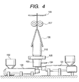
Fig. 4 is a schematic constructural view of an
apparatus of forming an intermediate transfer belt
(two layers) of the present invention;
Fig. 5 is a drawing showing a method of testing
a contact between an intermediate transfer belt and
electrophotographic photosensitive member;
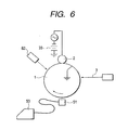
Fig. 6 is a drawing showing a method of
measuring light portion potential and dark portion
potential of an electrophotographic photosensitive
member;
Fig. 7 is a schematic constructural view of a
process cartridge constructed by connecting together
an electrophotographic photosensitive member unit and
an intermediate transfer belt unit used in Examples
and Comparison Examples;
Fig. 8 is a schematic constructural view of an
intermediate transfer belt unit; and
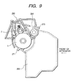
Fig. 9 is a schematic constructural view of an
electrophotographic photosensitive member unit.
DETAILED DESCRIPTION OF THE PREFERRED EMBODIMENTS
The present invention will be described in
further detail below.
In the present invention, as a result of study
on simplification of maintenance and miniaturization
of the main body as well as the cartridge,
enhancement in cost-saving and improvement of image
quality, the initial goal has been attained by
adopting several constructions together for a process
cartridge in which an intermediate transfer belt and
an organic electrophotographic photosensitive member
are integrated, and also primary transfer means for
primarily transferring a toner image on the
electrophotographic photosensitive member to the
intermediate transfer belt is further integrated.
That is, the present invention has the features
that after the electrophotographic photosensitive
member and the intermediate transfer belt are brought
into contact with each other under a linear pressure
of 0.5 N/cm to form a contact part, and are left to
stand for 10 hours in an environment of 45°C/95%RH,
differences in the dark portion potential and the
light portion potential of the electrophotographic
photosensitive member between the contact part and
the part not in contact with the intermediate
transfer belt (non-contact part) are respectively
less than 20%, and no crack having a length of not
less than 1 µm occurs in any of the surface of the
electrophotographic photosensitive member and the
surface of the intermediate transfer belt.
In the case where leaving in the environment of
45°C/95%RH for 10 hours does not cause such a crack
to occur, few problems occurs under actual
transportation and use conditions, and it can make
good performance available as an intermediate
transfer belt-electrophotographic photosensitive
member integrated process cartridge.
It is more preferable that even leaving for 336
hours in the above described environment does not
cause a crack having a length of not less than 1 µm
to occur in any of the surface of the
electrophotographic photosensitive member and the
surface of the intermediate transfer belt.
In case of occurrence of the crack of not less
than 1 µm, there may be no problem during the initial
stage, but repeated image forming will enlarge the
crack and bring toner into melt attachment thereto,
giving rise to a problem that a blank area is formed
in the image, and cracking or spot-like image occurs
in the white background occur.
In addition, even if no crack occurs on the
surface of the electrophotographic photosensitive
member, if the differences in the dark portion
potential and the light portion potential of the
electrophotographic photosensitive member between the
contact part and the non-contact part are
respectively not less than 20%, streaks of thin
density may appear on the solid image, and streaks of
high density may occur on the light color image.
In particular, these image problems are
remarkable in the electrophotographic apparatus of
digital system with not less than 600 dpi.
In order to obtain such a characteristic, the
materials that may migrate or move when the
intermediate transfer belt and the
electrophotographic photosensitive member are brought
into contact need to be made less, or made into a
form not apt to be moved, and there are several
methods.
In particular, there are a method in which as
various kinds of additives such as resistance
adjusting agent materials of high molecular weight
that hardly move in molecule level and conductive
filler such as carbon black etc. are selected for use
instead of movable materials having a low molecular
weight and a method in which the intermediate
transfer belt and/or the electrophotographic
photosensitive member is heated after produced or is
put under a reduced pressure and the like so that
volatile components of low molecular weight are
removed and the like.
In addition, there is a method in which an
inert particle additive is mixed into or attached to
the intermediate transfer belt and/or the
electrophotographic photosensitive member to provide
extremely micro protrusions on their surfaces so that
the contact area therebetween is reduced and movement
of matters is prevented, and a method in which the
binder resin of the intermediate transfer belt and/or
the electrophotographic photosensitive member is made
into a form having a higher molecular weight or
cross-linked so that movement of matters of low
molecule weight is prevented and the like.
The layer containing charge transporting
material that the electrophotographic photosensitive
member used for the process cartridge of the present
invention may preferably have a thickness of 10 to 60
µm, more preferably 15 to 40 µm.
In addition, the charge transporting material
may preferably be in a content of 20 to 80 % by
weight, more preferably 30 to 60 % by weight based on
the total weight of the layer that contains charge
transporting material.
When the layer containing charge transporting
material has a film thickness larger than 60 µm, or
when the charge transporting material is in a content
of less than 20 % by weight, the sensitivity may
lower.
On the other hand, in order to satisfy the
above described feature in the present invention, the
film thickness is preferably controlled to be not
less than 10 µm while the charge transporting
material is preferably controlled to be not more than
80 % by weight.
Exceeding these ranges, the durability of the
intermediate transfer belt and the
electrophotographic photosensitive member decreases,
and at the time when the intermediate transfer belt
and the electrophotographic photosensitive member are
brought into contact at high temperature/high
humidity and stored for a long period, it will become
highly possible that a crack occurs in the
intermediate transfer belt or the electrophotographic
photosensitive member.
Here, the layer containing charge transporting
material refers to, in the case where the
photosensitive layer the electrophotographic
photosensitive member has is a single layer type
photosensitive layer containing the charge generation
material and the charge transporting material in a
single layer, that single layer type photosensitive
layer, and, in the case where the photosensitive
layer is a lamination type photosensitive layer which
has a charge generation layer containing charge
generation material and a charge transport layer
containing charge transporting material in a
laminated form, to the charge transport layer.
In terms of the electrophotographic properties,
the layer construction of the photosensitive layer is
preferably a lamination type photosensitive layer in
which a charge generation layer and a charge
transport layer are laminated in this order from the
bottom.
In addition, as the binder resin to be utilized
for the electrophotographic photosensitive member
using organic photoconductive material, polyester,
polyurethane, polyarylate, polyethylene, polystyrene,
polybutadiene, polycarbonate, polyamide,
polypropylene, polyimide, polyamideimide, polysulfone,
polyaryl ether, polyacetal, phenolic resin, acrylic
resin, silicone resin, epoxy resin, urea resin,
allylic resin, alkyd resin, butyral resin, the like
can be mentioned.
Among these, in particular, it is preferable
that the charge transport layer contains
polycarbonate or polyarylate as binder resin, from
the point of view that such a phenomena that the
additive existing in the electrophotographic
photosensitive member such as the charge transporting
material in the present invention is shifted to the
intermediate transfer belt is made to hardly take
place.
In addition, nothing in particular will limit
the charge generation material as well as the charge
transporting material if they can make features of
the present invention available.
As the charge generation material, for example,
phthalocyanine pigment, polycyclic pigment, azo
pigment, perylene pigment, indigo pigment,
quinacridone pigment, azurenium salt dye, squa-rylium
dye, cyanine dye, pyrylium dye, thiopyrylium dye,
xanthene pigment, quinoneimine pigment,
triphenylmethane pigment, styryl pigment, selenium,
selenium-tellurium, amorphous silicon, cadmium
sulfide, and the like can be mentioned.
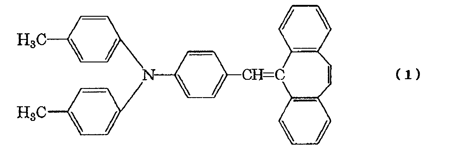
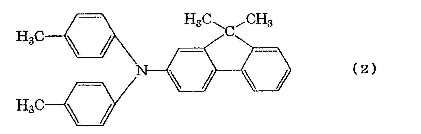
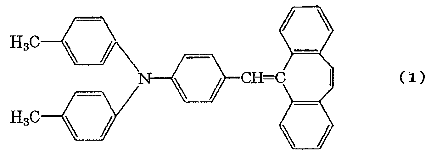
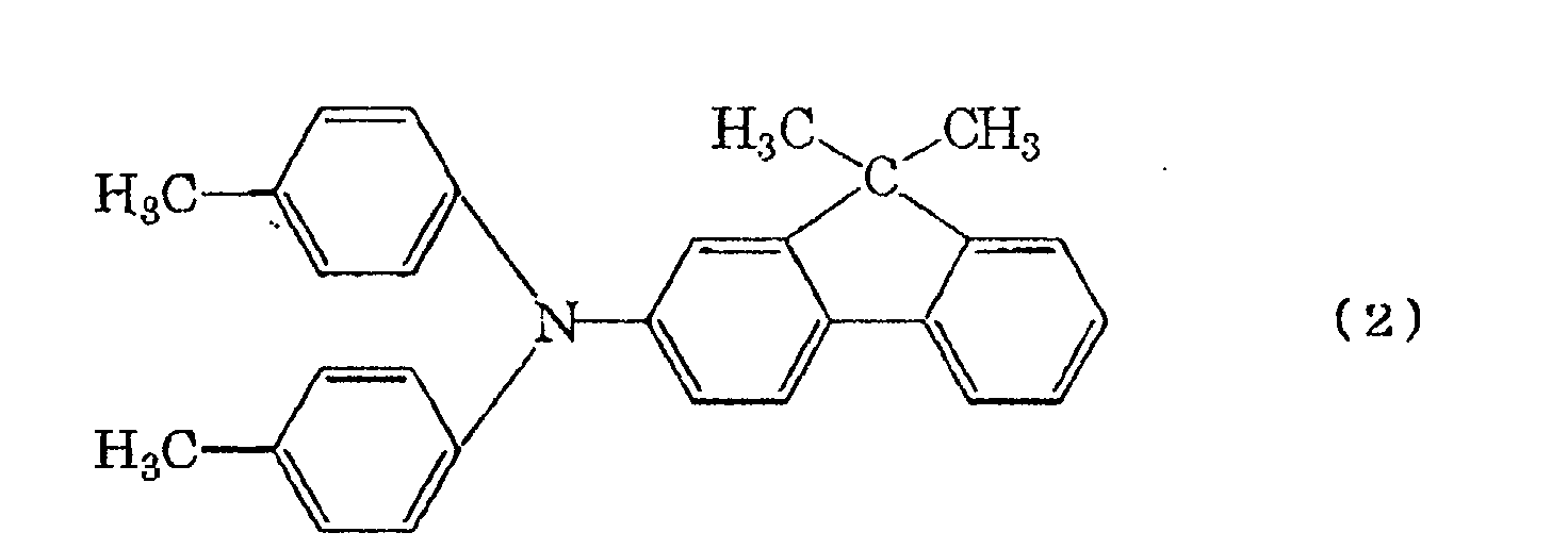
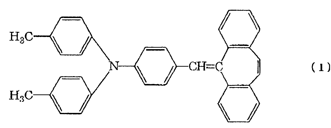
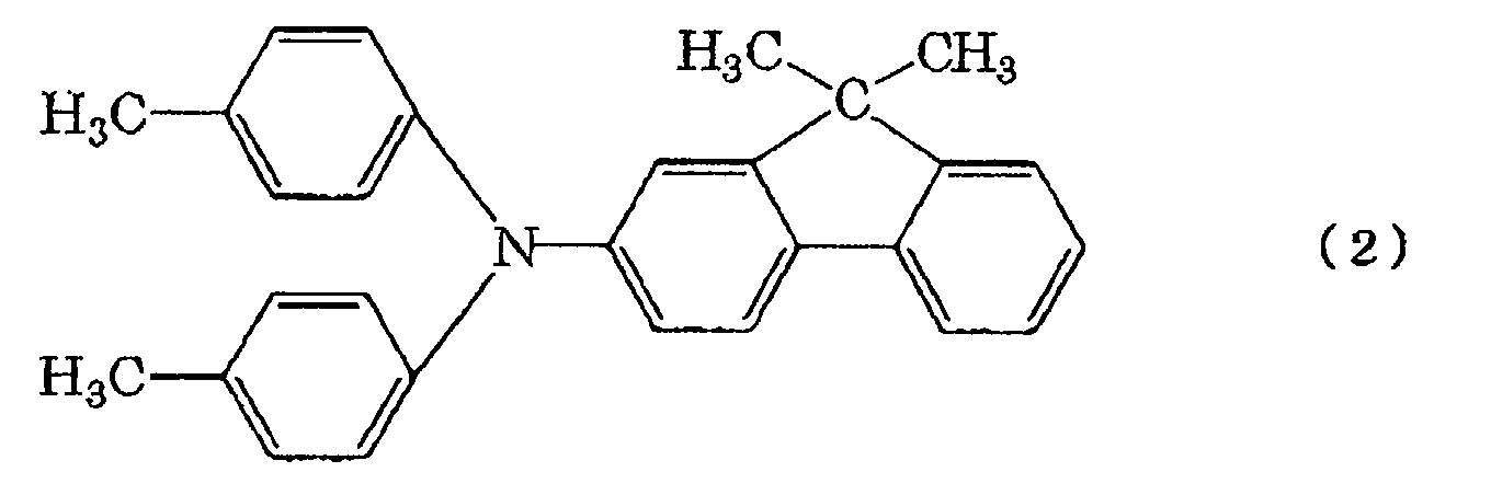
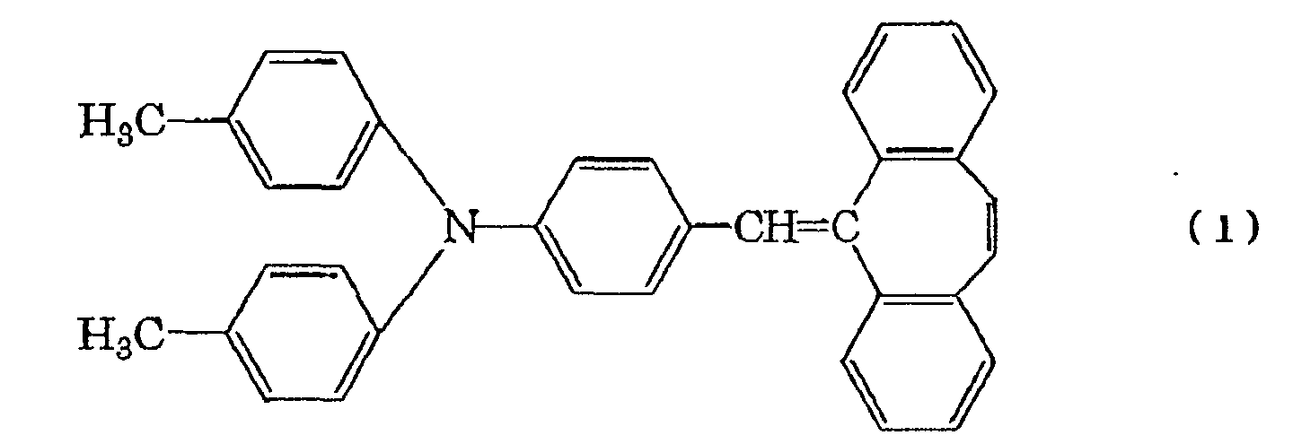
As the charge transporting material, pyrene
compounds, carbazole compounds, hydrazone compounds,
N,N-dialkylaniline compound, diphenylamine compound,
triphenylamine compound, triphenylmethane compounds,
pyrazoline compounds, styryl compounds, stilbene
comprounds, and the like can be mentioned, but the
charge transporting material having structure
represented by the following formula(1) or the charge
transporting material having structure represented by
the following formula(2) is preferable from the point
of view that those materials do not tend to move even
when they are in contact with the intermediate
transfer belt for a long period at high temperature
and high humidity and no streak-like image defect due
to the attachment of those materials to the
intermediate transfer belt is formed and that
electrifying deterioration is less and residual
potential can be reduced with high sensitivity and
the like.
In addition, as the charge transporting
material, the charge transporting material having
structure represented by the above described formula
In addition, on the photosensitive layer, a
protecting layer may be formed for the purpose of
protecting the photosensitive layer.
Film thickness of the protecting layer is
preferably 0.01 to 20 µm and moreover preferably 0.1
to 10 µm.
The protecting layer may contain the above
described charge generation material or charge
transporting material, metal as well as oxide thereof,
nitrides, salts, alloy and moreover conductive
material such as carbon.
As the binder resin to be used for the
protecting layer, polyester, polyurethane,
polyarylate, polyethylene, polystyrene, polybutadiene,
polycarbonate, polyamide, polypropylene, polyimide,
polyamideimide, polysulfone, polyallyl ether,
polyacetal, phenolic resin, acrylic resin, silicone
resin, epoxy resin, urea resin, allylic resin, alkyd
resin, butyral resin, and the like can be nominated.
Moreover, reactive epoxy, (meta) acrylic monomer or
oligomer can be used after subject to mixture and
hardening.
In addition, as the supporting member used for
the electrophotographic photosensitive member, metals
such as iron, copper, nickel, aluminum, titanium, tin,
antimony, indium, lead, zinc, gold and silver, alloy
thereof, or oxides thereof or carbon, conductive
resins and the like can be used. The shape of the
supporting member includes cylinder type, belt type
and sheet type. In addition, the above described
conductive material may be molded and processed, but
may be coated as a paint or may be evaporated and
deposited.
An intermediate layer may be provided between
the supporting member and the photosensitive layer.
The intermediate layer, which mainly consists of
binder resin, may contain the above described
conductive material or acceptor.
As the binder resin forming the intermediate
layer, polyester, polyurethane, polyarylate,
polyethylene, polystyrene, polybutadiene,
polycarbonate, polyamide, polypropylene, polyimide,
polyamideimide, polysulfone, polyaryl ether,
polyacetal, phenolic resin, acrylic resin, silicon
resin, epoxy resin, urea resin, allylic resin, alkyd
resin, butyral resin, and the like can be mentioned.
In addition, for the method of forming the
above described respective layers, the method such as
vapor deposition or coating is adopted. For coating,
bar coater, knife coater, roller coater, attriter,
spray, dip coating, electrostatic coating, powder
coating, or the like are used.
In addition, the process cartridge of the
present invention is preferably arranged to have
charge providing means to give electric charges in
polarity opposite to the polarity of the toner at the
time of the primary transfer to the toner on the
intermediate transfer belt to return the toner on the
intermediate transfer belt to the electrophotographic
photosensitive member at the contact part between the
intermediate transfer belt and the
electrophotographic photosensitive member to clean
the intermediate transfer belt.
As means to electrify the toner to the opposite
polarity, a blade charger and a corona charger can be
used.
The toner thus returned to the
electrophotographic photosensitive member from the
intermediate transfer belt is removed with
electrophotographic photosensitive member cleaning
means such as a cleaning blade.
This intermediate transfer belt cleaning system
gives rise to a significant effect in miniaturization
and cost reduction of process cartridge compared with
a system with cleaning blades, etc. being provided in
the electrophotographic photosensitive member and the
intermediate transfer belt respectively and with
feeding mechanism and a container for waste toner
being provided.
In addition, for the purpose of enhance in size
reduction and cost reduction (low pricing) of
intermediate transfer belt-electrophotographic
photosensitive integrated process cartridges, the
shape of the electrophotographic photosensitive
member incorporated in the process cartridge is also
important. From that view point, the
electrophotographic photosensitive member is
preferably shaped as a drum that has simple drive
mechanism and can be easily miniaturized, and the
diameter is preferably not more than 60 mm.
Moreover, enhancement in reduction of diameter
of the electrophotographic photosensitive member can
reduce the area of the contact part between the
intermediate transfer belt and the
electrophotographic photosensitive member, or the
portion where no contact does not occur but
approaching with extremely close distance takes place,
thereby gives rise to an effect to minimize the
region where a problem occurs during long period
storage.
In addition, the method in which the
intermediate transfer belt is placed over two rollers
can enhance reduction in the number of components and
miniaturization can be accelerated.
Among the rollers over which the intermediate
transfer belt is placed, the roller for applying
tension onto the intermediate transfer belt (tension
roller) may preferably slide at least 1 mm or more in
the elongating direction of the intermediate transfer
belt in order to correspond with elongation of the
intermediate transfer belt, and in order that the
intermediate transfer belt is certainly driven
without slipping, the intermediate transfer belt is
preferably placed over the rollers with force of 5 N
or more.
In addition, making the process cartridge
separable to an electrophotographic photosensitive
member unit having the electrophotographic
photosensitive member and an intermediate transfer
belt unit having the intermediate transfer belt, and
providing connecting means to connect the
electrophotographic photosensitive member unit and
the intermediate transfer belt unit, a user will be
able to remove the process cartridge from the main
body of the electrophotographic apparatus and
thereafter split the removed process cartridge into
the electrophotographic photosensitive member unit
and the intermediate transfer belt unit and replace
only the unit having reached its end of life and the
cost bearing of the user can be alleviated.
In addition, from the view point of obtaining a
good image, the range of volume resistivity of the
intermediate transfer belt is preferably 1 × 10⁶ to
8 × 10¹³ Ω·cm. With the volume resistivity being less
than 1 × 10⁶ Ω·cm, the resistance is too low to give
sufficient transfer electric field and may give rise
to lack of images and rough images. On the other
hand, with the volume resistivity being higher than
8 × 10¹³ Ω·cm, the transfer voltage needs to be set
high, and the power supply may be enlarged or cost
increase may be introduced.
In addition, the wall thickness of the
intermediate transfer belt is preferably 40 to 300 µm.
With less than 40 µm, the intermediate transfer belt
may lack in form stability to tend to give rise to
unevenness in thickness, and its enduring intensity
is insufficient, and breaking or a crack may occur.
On the other hand, with more than 300 µm, the
quantity of materials used increases, making costs
higher, and moreover, the peripheral speed balance
between the interior face and the exterior face of
the intermediate transfer belt in the roller portion
over which the intermediate transfer belt is placed,
thus such a problem as image scattering due to
elongation/contraction of the exterior face is apt to
occur. Also, such a problem that the intermediate
transfer belt may exhibit a decreased bending
endurance and become more rigid so that the driving
torque may increase and the main body of the
electrophotographic apparatus may be enlarged or cost
increase may be introduced is brought about.
The process cartridge of the present invention
is set to be the process cartridge integrally
supporting the intermediate transfer belt and the
electrophotographic photosensitive member in one body,
but it goes well if they are in one body at the time
when a user use them, and considering handling them
during the production process and simplicity in
dismantling thereof after collection, for example, a
designing that enables separation into several units
such as the intermediate transfer belt unit and the
electrophotographic photosensitive member unit is
preferably adopted.
The method of forming the intermediate,
transfer belt may be a method of producing seamless
belts. As the producing method, a method that
features high manufacturing efficiency and can
control costs is preferable.
As such a method, such a method that executes
continuous melt extrusion from a circular die and
thereafter cuts the extruded product into a form with
a necessary length to produce a belt can be mentioned.
For example, inflation molding is suitable.
A preferable example of method for producing
the intermediate transfer belt of the present
invention will be described below.
An apparatus for forming the intermediate
transfer belts of the present invention is
schematically shown in FIG. 3. The present apparatus
basically comprises an extruder, an extruder die and
a gas blowing unit.
Firstly, an extrusion resin, a conducting agent,
and additives etc. are preliminarily mixed in advance
in accordance with a desired formulation and
thereafter kneaded and dispersed to prepare an
extrusion material, which is then put into a hopper
102 provided to an extruder 100.
The extruder 100 has a preset temperature and
extruder screw construction which are selected so
that the extrusion material may have a melt viscosity
necessary for enabling the extrusion into a belt in
the subsequent steps and also the materials can
uniformly be dispersed each other.
The extrusion material is melt-kneaded in the
extruder 100 into a melt, which then enters the
cylinder-type extruder die 103. In the cylinder-type
die 103, a gas inlet passage 104 is disposed, and air
is blown into the center of the cylinder-type die 103
from the gas inlet passage 104 so that the melted
body having passed through the die 103 inflates while
scaling up in the radius direction to be a cylinder
film 110.
At this time, as the gas to be blown in, beside
air, nitrogen, carbon dioxide or argon etc. can be
selected. The extruded product having thus inflated
into a cylinder is drawn upward while being cooled
with the external cooling ring 105.
Normally, for the inflation apparatus, a method
is adapted in which the product in the tubular form
is crushed from the left and the right with the
stabilizing plate 106 and folded into a sheet and it
is then sandwiched by a pinch roller 107 without the
internal air coming out so that it is drawn at a
constant speed.
Subsequently, the drawn film is cut with a
cutting apparatus 108 so as to provide a cylindrical
film in a desired size.
Next, heat processing involving molds is
preferably implemented for various purposes of
removing the migrating matters, adjusting the surface
flatness, improving the size accuracy, removing
crease left in the film at the time of forming, and
the like.
In particular, there is a method to use a pair
of cylinder molds with different diameters made of
material with different coefficient of thermal
expansion.
The coefficient of thermal expansion of the
cylinder mold with small diameter (internal mold) is
set to get larger than the coefficient of thermal
expansion of the cylinder mold with large diameter
(external mold), and after this internal mold is
covered with a molded tubular film, that internal
mold is inserted into the external mold in such a
fashion that the internal mold and the external mold
sandwich the tubular film. The gap between the molds
is given subject to calculation from the heating
temperature, difference in the coefficient of thermal
expansion between the internal mold, and the external
mold and the pressure regarded as necessary.
The molds set in order of the internal mold,
the tubular film, and the external mold are heated to
reach near softening point temperature of the resin.
The internal mold with larger coefficient of thermal
expansion is heated to expand larger than the
external mold and a uniform pressure is applied to
all over the tubular film. The temperature at this
time is adjusted to reach around the softening point
of the resin.
The surface of the resin film is pushed onto
the inner face of the external mold subjected to
toughness adjustment, the surface toughness of the
surface of the resin film is adjusted to reach an
optimal value, and at the same time, the matter
becoming a cause to give rise to cracks in the
electrophotographic photosensitive member is
evaporated or attached to the mold so as to be
removed from inside the film.
Thereafter, the film is cooled and taken away
from the mold to obtain a belt in which size and
surface properties are controlled.
Hereafter, reinforcement members and guide
members or position detecting members are attached as
the need arises and accurate cutting is implemented
so as to produce the intermediate transfer belt.
In addition, the above described description
relates to a single layer belt, and in case of a belt
of two-layer structure, as shown in Fig. 4, another
extruder 101 is additionally disposed, simultaneously
with the kneaded and melted product from the extruder
100, the kneaded and melted product from the extruder
110 is sent to the circular die 103 for two layers so
that the two layers are simultaneously enlarged and
expanded to obtain a two-layer belt.
Of course, for three layers and more, it goes
well if extruder and circular dies are prepared in
the number of layers.
Thus, intermediate transfer belts of not only
of a single layer but also multi-layer construction
can be formed in one step, and in short time and with
good size accuracy. Possibility of this short-time
forming means possibility of weight production and
low-cost production.
The thickness ratio of the circular die and the
tubular film formed is the ratio between the width of
the gap of the circular die (die slit) and the
thickness of the tubular film formed, and the latter
is preferably one third or less of the former, and
more preferably one fifth or less.
Likewise, the ratio of the diameter of the
circular die and the tubular film formed is to
express by percentage the ratio of the outer diameter
of the tubular film 110 to the outer diameter of the
die slit of the circular die 103, and preferably
falls within the range of 101% to 300%.
These express elongation state of the materials,
and with thickness ratio being larger than 1/3,
elongation may become insufficient so that drop in
intensity or defect such as unevenness in resistance
and thickness may take place. In addition, when the
outer diameter exceeds 300%, thickness unevenness is
apt to occur due to drop in forming stability.
Among extrusion materials to be used for an
intermediate transfer belt for use in the process
cartridge of the present invention, for a resin being
a main material, which is not limited in particular
if it fulfills features of the present invention,
olefin resin such as polyethylene and polypropylene,
polystyrene resin, acrylic resin, polyester resin,
polycarbonate, sulfur-containing resins such as
polysulfone and polyether sulfone as well as
polyphenylene sulfide, etc., fluorine resins such as
polyvinylidene fluoride and polyethylene-tetrafluoroethylene
copolymer, etc., polyurethane
resin, silicon resin, ketone resin, polyvinylinde
chloride, thermoplastic polyimide resin, polyamide
resin, modified polyphenylene oxide resin and the
like, various modified resins and copolymers of these
can be used alone or in combination of two or more
kinds of the resins. However, the present invention
will not be limited to the above described materials.
Next, additives for mixture to adjust electric
resistance value of the intermediate transfer belt to
be used in the process cartridge of the present
invention will not be limited in particular, and as
conductive filler to adjust resistance, carbon black
and various kinds of conductive metal oxides, etc.
are used and as non-filler system resistance
adjusting agent, an antistatic resin containing an
ether bond or a hydroxyl group, etc. in the molecule
or organic high-molecular compounds showing
electronic conduction are used.
Ion conducting agents with low molecular weight
such as various kinds of metallic salts and glycols
are apt to migrate or move to the electrophotographic
photosensitive member, and are not preferable in
general, but not all of the materials will cause
problems and the materials can use within such a
range that the features of the present invention are
obtainable.
Next, an example of an electrophotographic
apparatus using an intermediate transfer belt-electrophotographic
photosensitive member integrated
process cartridge of the present invention is shown
in Fig. 1.
Fig. 1 shows a full-color electrophotographic
apparatus (a photocopier or a laser beam printer).
Reference numeral 1 denotes an
electrophotographic photosensitive member of a
rotating drum type repeatedly used as a first image
bearing member, and is driven for rotation at a
predetermined peripheral velocity (process speed) in
the direction of an arrow.
The electrophotographic photosensitive member 1
undergoes electrical charging treatment uniformly at
a predetermined polarity and potential with the
(primary) charging means 2 in the course of the
rotation. To the power source 32 of the electrifying
means is applied a voltage formed by superimposing an
alternate current onto direct current, but only the
direct current will do.
Subsequently, the photosensitive member 1
receives light 3 from not-shown exposing means (color
separation-image forming exposure optical system of a
color image of original, scanning exposure system
with a laser scanner outputting laser beams modulated
in accordance with time-sequential electric digital
pixel signal of image information, and the like),
whereby an electrostatic latent image is formed
corresponding to the first color component image (for
example, yellow color component image) of the desired
full color image.
Next, the electrostatic latent image is
developed with a first-color, yellow toner Y, by use
of a first developing means (yellow color developing
means 41). At this time, the respective developing
means of second to forth developing means (magenta
color developing means 42, cyan color developing
means 43 and black color developing means 44) are
operated off not. to act on the electrophotographic
photosensitive member 1 and the first color, yellow
toner image is not affected by the second to forth
developing means.
The intermediate transfer belt 5 is driven for
rotation at the same peripheral speed as that of the
photosensitive member 1 in the direction of an arrow.
The above described first yellow toner image
formed and carried on the electrophotographic
photosensitive member 1 passes through the contact
part between the electrophotographic photosensitive
member 1 and the intermediate transfer belt 5, in the
course of which it is successively primarily
transferred to the external circumference face of the
intermediate transfer belt 5 by the aid of an
electric field formed by the primary transfer bias
applied onto the intermediate transfer belt 5 from
the primary transfer means 6.
The surface of the electrophotographic
photosensitive member 1 having completed transfer of
the first color yellow toner image to the
intermediate transfer belt 5 is cleaned with
electrophotographic photosensitive member cleaning
means 13.
Subsequently, likewise the second color magenta
toner image, the third color cyanogens toner image
and the forth color black toner image are
sequentially transferred superimposingly onto the
intermediate transfer belt 5, and a synthesized color
toner image corresponding to the intended full color
image is formed.
Reference numeral 7 denotes a secondary
transfer means (secondary transfer roller) that is
borne in parallel with the secondary transfer roller
8 and is disposed in the bottom face of the
intermediate transfer belt 5 in a state capable of
being separable therefrom.
The primary transfer bias for sequential
superimposing transfer of the first to the forth
toner images from the electrophotographic
photosensitive member 1 to the intermediate transfer
belt 5 is applied in a reverse polarity (+) to that
of the toner from the bias power source 30. The
voltage thus applied may be in the range of from
+100V to 2kV, for example.
In the step of primary transfer of the first to
the third color toner images from the
electrophotographic photosensitive member 1 to the
intermediate transfer belt 5, the secondary transfer
means 7 can be separated from the intermediate
transfer belt 5.
For further transfer of a synthesized color
toner image transferred onto the intermediate
transfer belt 5 to a transfer material P, the
secondary transfer means 7 are brought into contact
with the intermediate transfer belt 5, and the
transfer material P is fed to the contact part
between the intermediate transfer belt 5 and the
secondary transfer means 7 at a predetermined timing
from a paper feeding roller 11 through a transfer
material guide 10 and a secondary transfer bias is
applied to the secondary transfer means 7 from the
source 31. With the aid of this secondary transfer
bias, a synthesized color toner image is secondarily
transferred from the intermediate transfer belt 5 to
the transfer material P.
The transfer material P having received the
transfer of the toner images is then introduced into
the fixing means 15 to undergo heat fixing.
After completion of the transfer of the toner
images onto the transfer material P, electric charge
providing means (charge providing roller) 9 is
brought into contact with the intermediate transfer
belt 5, where the charge providing means is disposed
freely in a separate/contact state relative to the
charge providing means, and a bias with a reverse
polarity to that of the electrophotographic
photosensitive member 1 is applied so that electric
charges with a reverse polarity to that at the time
of the primary transfer are given to the toners not
transferred to transfer material P and remaining on
the intermediate transfer belt 5 (i.e., transfer
residual toners). To the bias power source 33 is
applied a voltage formed by superimposing a direct
current voltage to alternate current voltage.
The transfer residual toners charged in a
reverse polarity to that at the time of the primary
transfer are electrostatically transferred to the
electrophotographic photosensitive member 1 at the
contact part of the intermediate transfer member with
the electrophotographic photosensitive member 1 as
well as in the vicinity thereof so that the
intermediate transfer member is cleaned. Since this
step can be implemented simultaneously with the
primary transfer, reduction in throughput does not
occur.
This intermediate transfer belt cleaning system
will work only by addition of a charge providing
member for giving electric charges to the transfer
residual toner (electric charge providing means), and
compared with the case where cleaning means and a
waste toner box are separately installed on the
intermediate transfer belt, miniaturization as well
as cost reduction of the electrophotographic
apparatus can be achieved.
Moreover, since all of the waste toner gets
together to the waste toner container that is
attached to the electrophotographic photosensitive
member, the waste toner container is also replaced
when the process cartridge is replaced, and another
waste toner box is not needed to be replaced,
improving maintenance performance.
However, in this intermediate transfer belt
cleaning system, two kinds of steps of the primary
transfer step and returning of the transferring
residual toner to the electrophotographic
photosensitive member are carried out simultaneously,
and therefore, at the time when there is difference
in sensitivity or minute cracks on the surface in the
electrophotographic photosensitive member, the image
undergoing primary transfer is apt to be affected.
Accordingly, in case of adopting this
intermediate transfer belt cleaning system, it is
important in particular for the intermediate
transferring member and the electrophotographic
photosensitive member to satisfy the above described
features of the present invention. In other words,
this intermediate transfer belt cleaning system
activates the present invention and is preferable.
Next, an example of an intermediate transfer
belt-electrophotographic photosensitive member
integrated process cartridge of the present invention
will be described.
The process cartridge of the present invention
shown in Fig. 2 is constructed as a one-body unit
comprising an intermediate transfer belt 5, an
electrophotographic photosensitive member 1, charge
providing means 9, electrophotographic photosensitive
member cleaning means 13, and roller-shape primary
transfer means 6 to be housed in a not-shown frame
and to be made easily detachably mountable to the
main body of the electrophotographic apparatus.
In addition, the process cartridge shown in Fig.
2 comprises a mechanism to charge the transfer
residual toner in a reverse polarity to that of the
primary transfer as mentioned above, and to return
the toner to the electrophotographic photosensitive
member in the primary transfer part, that is, in the
present drawing, roller-shape charge providing means
(electric charge providing roller) 9 made of elastic
member with medium resistance.
In this drawing, as the electrophotographic
photosensitive member cleaning means, a cleaning
blade is adopted.
In this process cartridge, a not-shown waste
toner container is also integrated, the transfer
residual toner on the both of the intermediate
transfer belt and the electrophotographic
photosensitive member is discarded at the same time
when the cartridge is replaced and contributes to
improvement in maintenance performance.
In addition, the intermediate transfer belt is
placed over and around two rollers 8 and 12 so that
reduction in number of components and miniaturization
are achieved. Here, a driving roller 8 serves at the
same time as a facing roller to the electric charge
providing roller as well as a secondary transfer
facing roller.
A tension roller 12 that rotates following the
intermediate transfer belt has a sliding mechanism
and is brought into press contact in the direction of
an arrow with a compressing spring to give tension to
the intermediate transfer belt. Slide width thereof
is about 1 to 5 mm and the total pressure of the
spring is around 5 to 100 N.
In addition, the electrophotographic
photosensitive member 1 and the driving roller 8 have
a not-shown coupling so that the rotation drive force
is transmitted from the main body.
Measuring method on respective properties
related to the present invention will be shown below.
<Method of testing contact between intermediate
transfer belt and electrophotographic photosensitive
member>
As shown in Fig. 5, an intermediate transfer
belt 5 is placed over and around a rubber roller 12
with a diameter of 30 mm which is prepared by winding
rubber (the one which has already been confirmed to
give no influence to the intermediate transfer belt)
with a thickness of 5 mm and JIS hardness of 45°
around an aluminum cylinder having a diameter of 20
mm. Reference numeral 50 denotes a roller facing the
electrophotographic photosensitive member.
Reference numeral 12 denotes a tension roller
onto which a force of 20 N is applied in the
direction of the arrow.
The electrophotographic photosensitive member 1
is brought into contact with the intermediate
transfer belt with a force of linear pressure of 0.5
N/cm ±5%. The contacting portion is marked in
advance both in the intermediate transfer belt and
the electrophotographic photosensitive member.
Here, linear pressure is a numerical value
given by the force applied to the electrophotographic
photosensitive member being divided by length (cm) in
the direction of shaft where the intermediate
transfer belt and the electrophotographic
photosensitive member are brought into contact, and
with the contact length being 30 cm and the linear
pressure being 0.5 N, a total pressure of 15 N will
become necessary.
Moreover, this test apparatus is housed in a
not-shown least size box and is completely shaded and
volatile matters appeared inside the box will not be
arranged not to diffuse easily. However, the box is
designed not to be sealed completely but to has the
same humidity as that of the measuring environment.
This apparatus is placed in an environment of
high temperature and high humidity set at 45°C/95%RH
and calmly put for necessary time (10 hours or 336
hours).
<Method of observing the surfaces of intermediate
transfer belt and electrophotographic photosensitive
member>
Three portions of contacting parts which are
marked in the intermediate transfer belt and the
electrophotographic photosensitive member subjected
to leaving test and two portions of non-contacting
portions in the vicinity of the contacting part are
cut out in a size of 10 mm × 10 mm and existence of
cracks is confirmed by magnifying with a Scanning
Electron Microscope (SEM). In the case where there
is any crack, size thereof is measured.
<Light portion potential-dark portion potential
measuring method>
The electrophotographic photosensitive member
having undergone the contact test is set to an
apparatus shown in Fig. 6.
The electrophotographic photosensitive member 1
is caused to rotate in the direction of the arrow
with a not-shown motor and is charged uniformly with
a charging unit 2. In the present test apparatus, a
power source 32 in which direct currents are
superimposed onto alternate currents is used.
Reference numeral 3 denotes exposing light, reference
numeral 51 denotes a surface potentiometer which is
arranged to be able to record surface potentials
continuously with a recording apparatus 53.
Reference numeral 52 denotes a pre-exposing means,
which erase electric charges with intensive exposing
prior to charging.
As for measuring of the dark portion potential,
the electrophotographic photosensitive member 1 is
caused to rotate at a peripheral speed of 120 mm/s,
and without use of exposing light 3 but with pre-exposing
means 52 being used, the voltage of the
charging unit 2 is adjusted so that the surface
potential of the non-contacting portion is
approximately -600V.
Changes in the surface potential of
electrophotographic photosensitive member at this
time are recorded with the recording apparatus 53 to
cover five rotations of the electrophotographic
photosensitive member at an interval of 0.002 second.
Next, all the measured values are averaged.
Next, a numerical value with the largest
difference from the average value in the previously
marked portion contacting with the intermediate
transferring member is extracted for each rotation,
and the average over five rotations is obtained.
From these values, potential change amount (%) is
obtained with the following equation:
(Contact part potential average value-total potential
average value)/total potential average value × 100(%)
As for measuring of the light portion potential,
emitting intensity of the exposing light 3 is
adjusted so that the surface potential will be -150V.
Changes of potential are then recorded in the same
manner as in the dark portion potential and
calculated.
This value, which falls within the region of
not more than ±20%, can be said to fall within the
range of the present invention.
The description is made with reference to
negative charging, but charging polarity as well as
exposing wavelength is appropriately selected in
accordance with kinds of the electrophotographic
photosensitive member.
<Volume resistance measuring method>
As for the measuring apparatus, Super high
resistance meter R8340A (produced by Advantest) is
used as resistance meter, and as for the test sample
box, a test sample box for a super high resistance
meter TR42 (produced by Advantest) is used, but the
main electrode is set to have a diameter of 25 mm
while the guard ring electrode is set to have an
inner diameter of 41 mm and an outer diameter of 49
mm.
Samples are produced as follows.
At first, the intermediate transfer belt is cut
out into a disk of diameter of 56 mm with a puncher
or a sharp knife.
A one face of the disk piece cut out is
provided with an electrode all over its face with a
Pt-Pd vapor-deposition film, and the other face is
provided with a main electrode having a diameter of
25 mm and a guard electrode having an inner diameter
of 38 mm and an outer diameter of 50 mm with Pt-Pd
vapor-deposition film.
The Pt-Pd vapor-deposition film is obtained by
carrying out the deposition operation for two minutes
with the mild sputter E1030 (produced by Hitachi,
Ltd.).
Those that completed the deposition operation
are treated as measuring samples.
Measuring atmosphere is set to be 23°C/55%RH and
the measuring samples are in advance left to stand in
the above described measuring atmosphere for not less
than 12 hours.
As for measuring, discharge lasts for 10
seconds, charging lasts for 30 seconds and measuring
lasts for 30 seconds, and measuring is carrying out
with the application voltage of 100 V.
<Thickness measuring method>
As for thickness unevenness of the intermediate
transfer belt, it was measured in the dial gauge of
minimum value of 1 µm at 50 mm from the both ends of
the belt, and at four points at an equal interval in
the center in the periphery direction all over the
circumference, and 12 points in total were averaged
for one intermediate transfer belt.
The present invention will be described in
further detail below by giving Examples.
In the Examples, "part(s)" is part(s) by weight.
(Example 1)
<Method of producing an electrophotographic
photosensitive member>
An aluminum cylinder of diameter of 47 mm and
length of 270 mm was provided with a conductive layer
of film thickness of 20 µm made of conductive metal
oxide and phenol resin by way of dipping coating.
Thereafter the intermediate layer of film
thickness of 1 µm made of methoxymethylated nylon was
applied on the above described conductive layer, and
moreover, a charge generation layer of film thickness
of 0.05 µm containing gallium phthalocyanine as
charge generation material was formed thereon by way
of dipping coating.
Next, a charge transport layer of film
thickness of 20 µm made of 0.9 parts of charge
transporting material having the structure shown in
the following formula (1),
8.1 parts of charge transporting material having the
structure shown in the following formula (2)
and 10 parts of the polyarylate resin was provided on
the above described charge generation layer also by
way of dipping coating so that an electrophotographic
photosensitive member 1 in rigid drum shape of
diameter of approximately 47 mm.
An intermediate transfer belt was manufactured
with the following materials.
| Polyvinylidene fluoride resin (PVDF) | 100 parts |
| Polyetheresteramide (Pelestat NC6321: Produced by Sanyo Chemical Industries, Ltd.) | 11 parts |
| Zinc oxide | 25 parts |
These materials were melt-kneaded at 210°C by
means of a twin-screw extruder with a decompressor
inside the cylinder, and at the same time the
volatile components were removed under a reduced
pressure.
Thereafter, the mixture obtained was extruded
in the shape of a strand having a diameter of about 2
mm, followed by cutting into pellets. This was
regarded as a molding raw material (extrusion
material) 1.
The above described molding raw material 1 was
constructed to use polyetheresteramide being
resistance adjusting agent of high molecular weight
hardly giving rise to movement (relocation) of
matters for fulfilling the above described features
of the present invention and moreover to add zinc
oxide as a non-active inorganic powder so that
contact area with the electrophotographic
photosensitive member is reduced.
Next, in the molding apparatus shown in Fig. 3,
the molding die 103 was a circular die for single
layer with diameter of 100 mm and the slit was set to
0.8 mm.
The molding raw material 1 having been well
dried by heating, was put into a material hopper 102
of this molding apparatus, and heated and melted.
The molten product was extruded into a cylinder shape
at 210°C from the die.
An external cooling ring 105 is disposed around
the die, and air was blown from the circumference
onto the extruded film to effect cooling.
In addition, the air was blown into the
interior of the extruded tubular film from the gas
inlet passage 104 to cause the film to inflate while
scaling up to have a diameter of 140 mm. Thereafter,
the film was continuously drawn off at a constant
speed with a draw-off unit.
At this time, thickness of the film was
adjusted to 100 µm. Incidentally, introduction of
the air was stopped at the time when the diameter
reached the desired value.
Moreover, subsequent to the draw-off through
the pinch rollers, the tubular film was cut with a
cutter 108.
The film was cut in a length of 290 mm after
the thickness was stabilized to form a tubular film 1.
On the tubular film 1, the size and surface
smoothness were regulated and folds were removed by
means of a set of cylindrical molds made of metals
with different thermal expansion coefficient.
At first, the tubular film 1 was placed over
and around the internal mold with a higher thermal
expansion coefficient.
Next, the internal mold covered with the above
described film 1 was inserted into the external mold
with the inner face having been processed into a
smooth face followed by heating at 170°C for 40
minutes. Also at this time, removal of the volatile
components and low molecular weight components was
promoted.
After cooling, the tubular film 1 was removed
from the mold to cut the ends away and an meandering-preventing
member made of urethane elastomer was
attached to the rear face of the end to produce an
intermediate transfer belt 1 with a diameter of 140
mm, length of 250 mm and thickness of 100 µm.
Using this intermediate transfer belt 1 and the
electrophotographic photosensitive member 1, contact
tests were executed with the method of the present
invention.
The samples used in the contact tests consisted
of three respectively for image confirmation, for
surface crack confirmation and for potential
confirmation as a set.
These samples were left to stand under the
environment of high temperature and high humidity of
45°C/95%RH for 10 hours and 336 hours.
After the contact test was completed, the
surface of one set each for the two laps was observed
by means of Scanning Electron Microscope, and no
crack was confirmed in the electrophotographic
photosensitive member and the intermediate transfer
belt in both of the sample left standing for 10-hour
and the sample left standing for 336-hour.
In addition, moreover, subject to leave
standing for one-day under 23°C/55%RH, the light
portion potential and the dark area potential of the
electrophotographic photosensitive member were
measured, and no difference between the contact
portion and non-contact portion was admitted, giving
rise to a good result.
Likewise, subject to leave standing for one-day
under 23°C/55%RH, the intermediate transfer belt and
the electrophotographic photosensitive member were
incorporated into an intermediate transfer belt-electrophotographic
photosensitive member integrated
process cartridge of a construction shown in Fig. 7.
This is treated as the process cartridge of
Embodiment 1.
The unit construction is roughly divided into
two parts in Fig. 7.
One is an electrophotographic photosensitive
member unit 50 shown in Fig. 8.
This is composed of as the main components in
an electrophotographic photosensitive drum frame 259
as one-body together with the waste toner container
252, the electrophotographic photosensitive member 1,
the charging means (charging roller) 2, the
electrophotographic photosensitive member cleaning
means (cleaning blade) 253, the screw 254 and the
drum shutter 255.
The other is an intermediate transfer belt unit
251 shown in Fig. 9.
For this, the intermediate transfer belt 5 is
placed over and around the intermediate transfer belt
frame 245 with the secondary transfer facing roller 8
and a tension roller (following roller) 12, and
primary transfer means (primary transfer roller) 258
disposed inside the intermediate transfer belt facing
the electrophotographic photosensitive member 1 and
charge providing means 9 disposed relative to the
secondary transfer facing roller (drive roller) 8.
Incidentally, the secondary transfer facing roller
(drive roller) 8 has function as a drive roller to
rotate the intermediate transfer belt 5.
As for these two units, protrusions 271
provided in the both right and left ends of the
electrophotographic photosensitive member frame 259
are respectively inserted into the positioning holes
272 provided in the intermediate transfer belt frame
245, and on the other hand, a nail 273 of hook part
of a snap fit form provided in the center of the
width direction of the electrophotographic
photosensitive member frame 259 is engaged into a
lock hole 274 of the intermediate transfer frame 245
for connection.
Here, the positioning holes 272 provided in the
intermediate transfer frame 245, and the lock hole
274 are provided with holes sized larger by a
predetermined quantity than the protrusions 271
provided in the electrophotographic photosensitive
member frame 259 and the hook part nail 273, and are
constructed to permit relative positional movements
of a predetermined amount between the
electrophotographic photosensitive member unit 250
and the intermediate transfer belt unit 251.
In addition, the positioning holes 272 are
provided with taper parts 272a for easy
attachment/detachment.
In Fig. 7, the hook nail 273 of the
electrophotographic photosensitive member unit 250 is
pushed so as to be taken off from the lock holes 274
of the intermediate transfer belt unit 251, and the
electrophotographic photosensitive member unit 250 is
rotated, and thus as shown in Fig. 8 and Fig. 9,
division into the electrophotographic photosensitive
member unit and the intermediate transfer belt unit
can be executed.
At the time of connection, on the contrary to
the above described, the protrusions 271 of the
electrophotographic photosensitive member unit 250
are inserted into the positioning holes 272 of the
intermediate transfer belt unit 251 and rotation in
the opposite direction to the case of removal is
implemented and the hook nail 273 is pushed into the
lock hole 274 to thereby connect the two units.
Thus, adopting such a construction of
dividability into an electrophotographic
photosensitive member unit and an intermediate
transfer belt unit and having connecting means to
connect the electrophotographic photosensitive member
unit and the intermediate transfer belt unit, a user
will be able to remove the process cartridge from the
main body of the electrophotographic apparatus and
thereafter divide the removed process cartridge into
the electrophotographic photosensitive member unit
and the intermediate transfer belt unit and replace
only the unit having reached its end of life and the
cost bearing of the user can be reduced.
The charge providing means 9 are brought into
connection with a not-shown feeder plate, and when
the process cartridge is incorporated into the main
body of the image forming apparatus, power supply
will become possible to the charge providing means 9
from the main body of the image forming apparatus
through the not-shown feeder plate. This can serve
to electrify the transfer residual toner on the
intermediate transfer belt 5 to the opposite polarity
against the photosensitive member.
After completion of image transfer onto the
transfer material P, charge providing means 9 are
brought into contact with the intermediate transfer
belt 5 disposed freely in a separate/contact state
and a bias of a reverse polarity against the
electrophotographic photosensitive member 1 is
applied so that charges of reverse polarity against
the primary transfer are given to the transfer
residual toner remaining on the intermediate transfer
belt 5 without being transferred onto the transfer
material P. Here, direct currents with alternate
currents were applied in a superimposition.
The above described transfer residual toners
electrified to the reverse polarity to that at the
time of the primary transfer are electrostatically
transferred to the electrophotographic photosensitive
member 1 at the contact part of the intermediate
transfer member with the electrophotographic
photosensitive member 1 as well as in the vicinity
thereof so that the intermediate transfer member is
cleaned. Since this step can be implemented
simultaneously with the primary transfer, reduction
in throughput does not occur.
The spring pressure of the tension roller
(following roller) was 20 N totaling the right and
the left parties with the slide amount of 2.5 mm and
the diameter of the tension roller (following roller)
and the secondary transfer facing roller (drive
roller) was 28 mm for use.
This intermediate transfer belt-electrophotographic
photosensitive member integrated
process cartridge was disposed in the
electrophotographic apparatus shown in Fig. 1, and
full color image print test was carried out to 80
g/m2 paper under the same environment.
The developing apparatus used at this occasion
was set to adopt 600 dpi digital laser system.
The obtained image was evaluated visually,
giving rise to good full color image without any
problem such as color unevenness as well as faulty
transfer.
In addition, the intermediate transfer belt 1
was brought into resistance measuring with the test
method of the present invention, resulting in the
volume resistance value (volume resistivity) being
9.8 × 10¹¹ Ω·cm.
In addition, moreover as the final test,
transportation test of the process cartridge of
Example 1 was carried out.
The test method was to transport a not yet used
process cartridge between Tokyo and Sydney by sea,
and thereafter by airmail on the way back so as to
confirm existence of occurrence of problems at the
time of transportation with high temperature and high
humidity environment on a ship and transportation by
air being simultaneously executed.
After transportation, the collected process
cartridge underwent a likewise print test as
described above, an image without any problem was
obtained as well, proving its performance without any
problems even after long-term transportation.
Evaluation results are shown in Table 1 and
Table 2.
(Example 2)
An
intermediate transfer belt 2 was produced in
the same manner as in Example 1 except that
composition ratio was changed as follows.
| Polyvinylidene fluoride resin (PVDF) | 100 parts |
| Polyetheresteramide (Pelestat NC6321: Produced by Sanyo Chemical Industries, Ltd.) | 8 parts |
| Perfluorobutane sulfonic acid potassium | 2 parts |
| Zinc oxide | 25 parts |
Perfluorobutane sulfonic acid potassium was
featured by its aptness not to be deposited on the
surface of the intermediate transfer belt under high
temperature and high humidity with low water
solubility in salts and its compatibility with
polyvinyliden fluoride resin (PVDF) because of
containing fluorine.
On the intermediate transfer belt 2,
measurement on properties, image print test and
transportation test were carried out in the same
manner as in Example 1. The results thereof were as
good as in Example 1.
Evaluation results are shown in Table 1 and
Table 2.
(Example 3)
Composition ratio was changed as follows, and
in accordance with the resin, mixing as well as
molding and mold heating temperature were raised to
260°C. In addition, in molding processing, inner
coarseness on the face of the outer mold was changed
to become slightly coarse. Otherwise, an
intermediate'transfer belt 3 was produced in the same
manner as Example 1.
| Polycarbonate A | 100 parts |
| Conductive carbon black | 25 parts |
The conductive agent in the present example is
carbon black, being featured by exclusion of organic
matter of low molecular weight badly affecting in
particular the electrophotographic photosensitive
member.
On the intermediate transfer belt 3,
measurement on properties, image print test and
transportation test were carried out in the same
manner as in Example 1. The results thereof were as
good as in Example 1.
Evaluation results are shown in Table 1 and
Table 2.
(Example 4)
An electrophotographic photosensitive member 2
was produced in the same manner as in Example 1
except that polycarbonate Z was used instead of
polyarylate. Except that this electrophotographic
photosensitive member 2 was used, measurement on
properties, image print test and transportation test
were carried out in the same manner as in Example 1.
The results thereof were as good as in Example 1.
Evaluation results are shown in Table 1 and
Table 2.
(Comparative Example 1)
A comparative
intermediate transfer belt 1 was
produced in the same manner as in Example 1 except
that composition ratio was changed as follows.
| Polyvinylidene fluoride resin (PVDF) | 100 parts |
| Polyetheresteramide (Pelestat NC6321: Produced by Sanyo Chemical Industries, Ltd.) | 20 parts |
| Perfluorobutane sulfonic acid | 4 parts |
| Dioctyl phthalate (plastic agent) | 1 part |
On the comparative intermediate transfer belt 1,
tests as in Example 1 and the image print test were
carried out. As the result, a small number of cracks
of length of 0.5 to 0.8 µm occurred on the
electrophotographic photosensitive member which
underwent the contact test of 10 hours, and moreover,
a number of cracks of length of 30 to 150 µm were
discovered on the electrophotographic photosensitive
member which underwent the contact test of 336 hours.
In addition, potential of the
electrophotographic photosensitive member which
underwent the contact test of 10 hours was measured.
As the result, the light portion potential in the
portion that was contacting with the intermediate
transfer belt was higher than the neighborhood by 21%,
and on the contrary, the dark portion potential of
the contacting portion was lower by 15%. Moreover,
as for potential of the portion, that was contacting
with the intermediate transfer belt, of the
electrophotographic photosensitive member which
underwent the contact test of 336 hours, the light
portion potential was higher by 32% and the dark
portion potential was lower than the neighborhood by
21%.
The image was confirmed with the method of
Example 1 by using this intermediate transfer belt
and the electrophotographic photosensitive member.
As for the electrophotographic photosensitive
member left standing for 10 hours, image density
becomes higher in the portion corresponding to the
contact part with the intermediate transfer belt in a
half tone image or a white image, and as for the
electrophotographic photosensitive member left
standing for 336 hours, more remarkable streaks of
high density occurred on a half tone or a solid white
image, and for a high density image, on the contrary,
thin color streaks occurred.
Moreover, also a process cartridge that
underwent the transportation test gave rise to
streaks of high density occurred on a half tone or a
white image, and was found out not to be able to
endure a long-period transportation.
Evaluation results are shown in Table 1 and
Table 2.
(Comparative Example 2)
Composition ratio of the intermediate transfer
belt was changed as follows, and after respective
materials were mixed well and were poured into
centrifugal molding mold and were rotated while the
solvent was evaporated and underwent urethane forming
reaction, and thereby a belt made of urethane
elastomer of diameter of 140 mm and thickness of 500
µm by way of centrifugal molding method, and subject
to end cutting as well as with meandering-preventing
rib being stuck, a comparative
intermediate transfer
belt 2 was produced.
| Polyester polyol (synthesized from adipic acid and butylenes glycol) | 100 parts |
| Isocyanate (tolylene diisocynanate (TDI)) | 20 parts |
| Conductive carbon black | 20 parts |
| Methyl isobutyl ketone (solvent) | 100 parts |
On the comparative intermediate transfer belt 2,
measurement of properties as in Example 1 and the
image print test were carried out. As the result a
number of cracks of 3 to 12 µm were discovered in the
portion where the electrophotographic photosensitive
member which underwent the contact leaving test of 10
hours and the intermediate transfer belt were brought
into contact.
Moreover, it was supposed that the
electrophotographic photosensitive member left
standing for 336 hours has a number of cracks of 500
to 800 µm in the intermediate transfer belt contact
part, and since a small number of cracks of length
about 15 to 30 µm occurred also in the vicinity of
the intermediate transfer belt contact part, even the
portion where no direct contact takes place is also
influenced by the evaporated components such as
solvent.
In addition, as for the potential difference
between the portion where this electrophotographic
photosensitive member contacts the intermediate
transfer belt and the circumference, there is no
significant difference in the dark portion potential
after leave to stand for 10 hours, +8% in the light
portion potential, and +18% in the light portion
potential after leave for 336 hours.
As for the image print test, in the
electrophotographic photosensitive member left
standing for 10 hours, there are streak-like portions
with high image density in the half tone image
corresponding with the intermediate transfer belt
contact part, and moreover, a blur of characters and
fine lines took place in the contact part and in the
vicinity thereof.
The one after leave to stand for 336 hours gave
rise to more remarkable image defects.
Moreover, the process cartridge subject to
transportation test also gave rise to such a
phenomenon as described above, and was found out to
be unable to endure long-period transportation.
Evaluation results are shown in Table 1 and
Table 2.
| | crack (µm) |
| | 10 hours | 336 hours |
| | electrophotographic photosensitive member | intermediate transfer belt | electrophotographic photosensitive member | intermediate transfer belt |
| | contact part | vicinity of contact part | contact part | vicinity of contact part | contact part | vicinity of contact part | contact part | vicinity of contact part |
| Example 1 | none | none | none | none | none | none | none | none |
| Example 2 | none | none | none | none | none | none | none | none |
| Example 3 | none | none | none | none | none | none | none | none |
| Example 4 | none | none | none | none | none | none | none | none |
| Comparative Example 1 | 0.5-0.8 | none | none | none | 30-150 | none | none | none |
| Comparative Example 2 | 3-12 | none | none | none | 500-800 | 15-30 | none | none |
| | potential of electrophotographic photosensitive member in the contact part | image evaluation | intermediate transfer belt resistance (Ω-cm) | image evaluation after transportation test |
| | 10 hours | 336 hours | 10 hours | 336 hours |
| | dark portion potential (%) | light portion potential (%) | dark portion potential (%) | light portion potential (%) |
| Embodiment 1 | 0 | 0 | 0 | 0 | good | good | 9.80 x 10¹¹ | good |
| Embodiment 2 | 0 | 0 | 0 | 0 | good | good | 1.20 × 10¹¹ | good |
| Embodiment 3 | 0 | 0 | 0 | 0 | good | good | 8.50 × 10⁸ | good |
| Embodiment 4 | 0 | 0 | 0 | 0 | good | good | 9.80 × 10¹¹ | good |
| Comparative Example 1 | -15 | +21 | -21 | +32 | streak-like image defect | streak-like image defect | 9.00 × 10⁹ | streak-like image defect |
| Comparative Example 2 | 0 | +8 | 0 | +18 | streak-like image defect-blur | streak-like image defect-blur | 9.50 × 10⁵ | streak-like image defect-blur |
According to the present invention, a process
cartridge that makes maintenance easy, can plan
miniaturization as well as cost reduction of the
apparatus to/from which it is attached/removed and
makes good images available and an
electrophotographic apparatus having the process
cartridge can be provided.
A process cartridge which is detachably
mountable to a main body of an electrophotographic
apparatus, including an electrophotographic
photosensitive member to carry a toner image; an
intermediate transfer belt having a contact part with
the photosensitive member, and a primary transfer
unit to primarily transfer the toner image at the
contact part from the photosensitive member to the
intermediate transfer belt, being integrally
supported in one body. After the contact part is
formed by the photosensitive member and the
intermediate transfer belt being brought into contact
with under a linear pressure of 0.5 N/cm and is left
for 10 hours in an environment of 45°C/95%RH,
differences in the dark portion potential and the
light portion potential of the photosensitive member
between the contact part and the non-contact part of
the photosensitive member are respectively less than
20%, and no crack having a length of not less than 1
µm occurs in any of the surfaces of the
photosensitive member and the intermediate transfer
belt. An electrophotographic apparatus having the
process cartridge is also disclosed.