EP1288692A1 - Structure for connecting a lens to a lens holder without using an adhesive - Google Patents
Structure for connecting a lens to a lens holder without using an adhesive Download PDFInfo
- Publication number
- EP1288692A1 EP1288692A1 EP02256001A EP02256001A EP1288692A1 EP 1288692 A1 EP1288692 A1 EP 1288692A1 EP 02256001 A EP02256001 A EP 02256001A EP 02256001 A EP02256001 A EP 02256001A EP 1288692 A1 EP1288692 A1 EP 1288692A1
- Authority
- EP
- European Patent Office
- Prior art keywords
- protrusions
- lens
- mounting surface
- triangle
- lens holder
- Prior art date
- Legal status (The legal status is an assumption and is not a legal conclusion. Google has not performed a legal analysis and makes no representation as to the accuracy of the status listed.)
- Withdrawn
Links
- 239000000853 adhesive Substances 0.000 title description 12
- 230000001070 adhesive effect Effects 0.000 title description 12
- 230000003287 optical effect Effects 0.000 claims description 40
- 238000000034 method Methods 0.000 claims description 20
- 239000011347 resin Substances 0.000 claims description 5
- 229920005989 resin Polymers 0.000 claims description 5
- 238000003466 welding Methods 0.000 claims description 2
- 230000002093 peripheral effect Effects 0.000 description 2
- 230000002411 adverse Effects 0.000 description 1
- 230000005540 biological transmission Effects 0.000 description 1
- 230000001678 irradiating effect Effects 0.000 description 1
- 239000000463 material Substances 0.000 description 1
- 239000004065 semiconductor Substances 0.000 description 1
Images



Classifications
-
- B—PERFORMING OPERATIONS; TRANSPORTING
- B29—WORKING OF PLASTICS; WORKING OF SUBSTANCES IN A PLASTIC STATE IN GENERAL
- B29C—SHAPING OR JOINING OF PLASTICS; SHAPING OF MATERIAL IN A PLASTIC STATE, NOT OTHERWISE PROVIDED FOR; AFTER-TREATMENT OF THE SHAPED PRODUCTS, e.g. REPAIRING
- B29C66/00—General aspects of processes or apparatus for joining preformed parts
- B29C66/50—General aspects of joining tubular articles; General aspects of joining long products, i.e. bars or profiled elements; General aspects of joining single elements to tubular articles, hollow articles or bars; General aspects of joining several hollow-preforms to form hollow or tubular articles
- B29C66/51—Joining tubular articles, profiled elements or bars; Joining single elements to tubular articles, hollow articles or bars; Joining several hollow-preforms to form hollow or tubular articles
- B29C66/53—Joining single elements to tubular articles, hollow articles or bars
- B29C66/534—Joining single elements to open ends of tubular or hollow articles or to the ends of bars
-
- B—PERFORMING OPERATIONS; TRANSPORTING
- B29—WORKING OF PLASTICS; WORKING OF SUBSTANCES IN A PLASTIC STATE IN GENERAL
- B29C—SHAPING OR JOINING OF PLASTICS; SHAPING OF MATERIAL IN A PLASTIC STATE, NOT OTHERWISE PROVIDED FOR; AFTER-TREATMENT OF THE SHAPED PRODUCTS, e.g. REPAIRING
- B29C65/00—Joining or sealing of preformed parts, e.g. welding of plastics materials; Apparatus therefor
- B29C65/02—Joining or sealing of preformed parts, e.g. welding of plastics materials; Apparatus therefor by heating, with or without pressure
- B29C65/08—Joining or sealing of preformed parts, e.g. welding of plastics materials; Apparatus therefor by heating, with or without pressure using ultrasonic vibrations
-
- B—PERFORMING OPERATIONS; TRANSPORTING
- B29—WORKING OF PLASTICS; WORKING OF SUBSTANCES IN A PLASTIC STATE IN GENERAL
- B29C—SHAPING OR JOINING OF PLASTICS; SHAPING OF MATERIAL IN A PLASTIC STATE, NOT OTHERWISE PROVIDED FOR; AFTER-TREATMENT OF THE SHAPED PRODUCTS, e.g. REPAIRING
- B29C66/00—General aspects of processes or apparatus for joining preformed parts
- B29C66/01—General aspects dealing with the joint area or with the area to be joined
- B29C66/05—Particular design of joint configurations
- B29C66/10—Particular design of joint configurations particular design of the joint cross-sections
- B29C66/12—Joint cross-sections combining only two joint-segments; Tongue and groove joints; Tenon and mortise joints; Stepped joint cross-sections
- B29C66/122—Joint cross-sections combining only two joint-segments, i.e. one of the parts to be joined comprising only two joint-segments in the joint cross-section
- B29C66/1222—Joint cross-sections combining only two joint-segments, i.e. one of the parts to be joined comprising only two joint-segments in the joint cross-section comprising at least a lapped joint-segment
-
- B—PERFORMING OPERATIONS; TRANSPORTING
- B29—WORKING OF PLASTICS; WORKING OF SUBSTANCES IN A PLASTIC STATE IN GENERAL
- B29C—SHAPING OR JOINING OF PLASTICS; SHAPING OF MATERIAL IN A PLASTIC STATE, NOT OTHERWISE PROVIDED FOR; AFTER-TREATMENT OF THE SHAPED PRODUCTS, e.g. REPAIRING
- B29C66/00—General aspects of processes or apparatus for joining preformed parts
- B29C66/01—General aspects dealing with the joint area or with the area to be joined
- B29C66/05—Particular design of joint configurations
- B29C66/10—Particular design of joint configurations particular design of the joint cross-sections
- B29C66/12—Joint cross-sections combining only two joint-segments; Tongue and groove joints; Tenon and mortise joints; Stepped joint cross-sections
- B29C66/122—Joint cross-sections combining only two joint-segments, i.e. one of the parts to be joined comprising only two joint-segments in the joint cross-section
- B29C66/1224—Joint cross-sections combining only two joint-segments, i.e. one of the parts to be joined comprising only two joint-segments in the joint cross-section comprising at least a butt joint-segment
-
- B—PERFORMING OPERATIONS; TRANSPORTING
- B29—WORKING OF PLASTICS; WORKING OF SUBSTANCES IN A PLASTIC STATE IN GENERAL
- B29C—SHAPING OR JOINING OF PLASTICS; SHAPING OF MATERIAL IN A PLASTIC STATE, NOT OTHERWISE PROVIDED FOR; AFTER-TREATMENT OF THE SHAPED PRODUCTS, e.g. REPAIRING
- B29C66/00—General aspects of processes or apparatus for joining preformed parts
- B29C66/01—General aspects dealing with the joint area or with the area to be joined
- B29C66/05—Particular design of joint configurations
- B29C66/20—Particular design of joint configurations particular design of the joint lines, e.g. of the weld lines
- B29C66/21—Particular design of joint configurations particular design of the joint lines, e.g. of the weld lines said joint lines being formed by a single dot or dash or by several dots or dashes, i.e. spot joining or spot welding
-
- B—PERFORMING OPERATIONS; TRANSPORTING
- B29—WORKING OF PLASTICS; WORKING OF SUBSTANCES IN A PLASTIC STATE IN GENERAL
- B29C—SHAPING OR JOINING OF PLASTICS; SHAPING OF MATERIAL IN A PLASTIC STATE, NOT OTHERWISE PROVIDED FOR; AFTER-TREATMENT OF THE SHAPED PRODUCTS, e.g. REPAIRING
- B29C66/00—General aspects of processes or apparatus for joining preformed parts
- B29C66/01—General aspects dealing with the joint area or with the area to be joined
- B29C66/05—Particular design of joint configurations
- B29C66/302—Particular design of joint configurations the area to be joined comprising melt initiators
- B29C66/3022—Particular design of joint configurations the area to be joined comprising melt initiators said melt initiators being integral with at least one of the parts to be joined
- B29C66/30221—Particular design of joint configurations the area to be joined comprising melt initiators said melt initiators being integral with at least one of the parts to be joined said melt initiators being point-like
-
- B—PERFORMING OPERATIONS; TRANSPORTING
- B29—WORKING OF PLASTICS; WORKING OF SUBSTANCES IN A PLASTIC STATE IN GENERAL
- B29C—SHAPING OR JOINING OF PLASTICS; SHAPING OF MATERIAL IN A PLASTIC STATE, NOT OTHERWISE PROVIDED FOR; AFTER-TREATMENT OF THE SHAPED PRODUCTS, e.g. REPAIRING
- B29C66/00—General aspects of processes or apparatus for joining preformed parts
- B29C66/01—General aspects dealing with the joint area or with the area to be joined
- B29C66/32—Measures for keeping the burr form under control; Avoiding burr formation; Shaping the burr
- B29C66/322—Providing cavities in the joined article to collect the burr
-
- G—PHYSICS
- G02—OPTICS
- G02B—OPTICAL ELEMENTS, SYSTEMS OR APPARATUS
- G02B7/00—Mountings, adjusting means, or light-tight connections, for optical elements
- G02B7/02—Mountings, adjusting means, or light-tight connections, for optical elements for lenses
- G02B7/022—Mountings, adjusting means, or light-tight connections, for optical elements for lenses lens and mount having complementary engagement means, e.g. screw/thread
-
- G—PHYSICS
- G11—INFORMATION STORAGE
- G11B—INFORMATION STORAGE BASED ON RELATIVE MOVEMENT BETWEEN RECORD CARRIER AND TRANSDUCER
- G11B7/00—Recording or reproducing by optical means, e.g. recording using a thermal beam of optical radiation by modifying optical properties or the physical structure, reproducing using an optical beam at lower power by sensing optical properties; Record carriers therefor
- G11B7/12—Heads, e.g. forming of the optical beam spot or modulation of the optical beam
- G11B7/135—Means for guiding the beam from the source to the record carrier or from the record carrier to the detector
- G11B7/1372—Lenses
-
- G—PHYSICS
- G11—INFORMATION STORAGE
- G11B—INFORMATION STORAGE BASED ON RELATIVE MOVEMENT BETWEEN RECORD CARRIER AND TRANSDUCER
- G11B7/00—Recording or reproducing by optical means, e.g. recording using a thermal beam of optical radiation by modifying optical properties or the physical structure, reproducing using an optical beam at lower power by sensing optical properties; Record carriers therefor
- G11B7/12—Heads, e.g. forming of the optical beam spot or modulation of the optical beam
- G11B7/22—Apparatus or processes for the manufacture of optical heads, e.g. assembly
-
- B—PERFORMING OPERATIONS; TRANSPORTING
- B29—WORKING OF PLASTICS; WORKING OF SUBSTANCES IN A PLASTIC STATE IN GENERAL
- B29C—SHAPING OR JOINING OF PLASTICS; SHAPING OF MATERIAL IN A PLASTIC STATE, NOT OTHERWISE PROVIDED FOR; AFTER-TREATMENT OF THE SHAPED PRODUCTS, e.g. REPAIRING
- B29C66/00—General aspects of processes or apparatus for joining preformed parts
- B29C66/01—General aspects dealing with the joint area or with the area to be joined
- B29C66/05—Particular design of joint configurations
- B29C66/302—Particular design of joint configurations the area to be joined comprising melt initiators
- B29C66/3022—Particular design of joint configurations the area to be joined comprising melt initiators said melt initiators being integral with at least one of the parts to be joined
- B29C66/30223—Particular design of joint configurations the area to be joined comprising melt initiators said melt initiators being integral with at least one of the parts to be joined said melt initiators being rib-like
-
- B—PERFORMING OPERATIONS; TRANSPORTING
- B29—WORKING OF PLASTICS; WORKING OF SUBSTANCES IN A PLASTIC STATE IN GENERAL
- B29C—SHAPING OR JOINING OF PLASTICS; SHAPING OF MATERIAL IN A PLASTIC STATE, NOT OTHERWISE PROVIDED FOR; AFTER-TREATMENT OF THE SHAPED PRODUCTS, e.g. REPAIRING
- B29C66/00—General aspects of processes or apparatus for joining preformed parts
- B29C66/40—General aspects of joining substantially flat articles, e.g. plates, sheets or web-like materials; Making flat seams in tubular or hollow articles; Joining single elements to substantially flat surfaces
- B29C66/47—Joining single elements to sheets, plates or other substantially flat surfaces
-
- B—PERFORMING OPERATIONS; TRANSPORTING
- B29—WORKING OF PLASTICS; WORKING OF SUBSTANCES IN A PLASTIC STATE IN GENERAL
- B29L—INDEXING SCHEME ASSOCIATED WITH SUBCLASS B29C, RELATING TO PARTICULAR ARTICLES
- B29L2011/00—Optical elements, e.g. lenses, prisms
- B29L2011/0016—Lenses
-
- B—PERFORMING OPERATIONS; TRANSPORTING
- B29—WORKING OF PLASTICS; WORKING OF SUBSTANCES IN A PLASTIC STATE IN GENERAL
- B29L—INDEXING SCHEME ASSOCIATED WITH SUBCLASS B29C, RELATING TO PARTICULAR ARTICLES
- B29L2031/00—Other particular articles
- B29L2031/737—Articles provided with holes, e.g. grids, sieves
Definitions
- This invention relates to a structure and a method for fixing a lens used in an optical disk drive or the like to a lens holder.
- An optical disk drive is an apparatus for writing information into an optical disk by the use of a laser beam and for reading information already written in the optical disk.
- the optical disk drive of the type has an optical pickup for irradiating the laser beam onto the optical disk and for detecting a reflected beam from the optical disk.
- the optical pickup comprises an objective lens for focusing or condensing the laser beam on the optical disk and a lens holder for holding the objective lens.
- the objective lens 40 has a flange 41 formed at its outer peripheral edge.
- the lens holder 50 has a through hole 51 for passing a laser beam and a stepped portion 52 for receiving the objective lens 40.
- the stepped portion 52 has a mounting surface 53 for mounting the flange 41 of the objective lens 40 and a plurality of adhesive-applying portions 54 extending outward from the mounting surface 53 at three positions equiangularly spaced in a circumferential direction of the mounting surface 53.
- the objective lens 40 and the lens holder 50 are fixedly connected or bonded to each other in the following manner.
- the objective lens 40 is fitted into the stepped portion 52 so that the flange 41 is placed on the mounting surface 53.
- an appropriate amount of UV-setting resin as an adhesive is applied to the adhesive-applying portions 54 of the lens holder 50 and a part of the mounting surface 53 corresponding to each of the adhesive-applying portions 54.
- ultraviolet light is irradiated to solidify or harden the UV-setting resin.
- the objective lens 40 is bonded to the lens holder 50 by the use of adhesive.
- adhesive it is difficult to obtain sufficient bonding strength between the objective lens 40 and the lens holder 50. Due to the thickness of the adhesive, the objective lens 40 may adhere to the lens holder 50 in a state in which the objective lens 40 is not flat on the lens holder 50.
- the adhesive may possibly be attached to an effective part of the objective lens 40 and inhibit transmission of the laser beam.
- the lens holder 50 must be greater in size than that required to receive the objective lens 40.
- a structure for connecting a lens to a lens holder having a mounting surface said lens having a flange placed on said mounting surface.
- said flange has a particular surface faced to said mounting surface and at least three protrusions on said particular surface, the mounting surface having a plurality of recesses formed at positions corresponding to said protrusions, each of said recesses having a depth smaller than a height of a corresponding one of said protrusions and a volume greater than that of said corresponding one, the protrusions being placed in said recesses, respectively, and ultrasonic welded to said lens holder.
- a method of connecting a lens to a lens holder having a mounting surface said lens having a flange which is placed on said mounting surface and has a particular surface facing said mounting surface.
- the method comprises the steps of providing said particular surface with at least three protrusions, providing said mounting surface with recesses formed at positions corresponding to said protrusions, each of said recess having a depth smaller than a height of a corresponding one of said protrusions and a volume greater than that of said corresponding one, facing said particular surface to said mounting surface so that said protrusions are received in said recesses, respectively, and ultrasonic welding said protrusions to said lens holder by the use of an ultrasonic welder.
- an optical pickup having the structure mentioned above.
- the optical pickup illustrated in the figure is adapted to be used in an optical disk drive mounted to an electronic apparatus such as a personal computer.
- the optical pickup comprises as a light emitting element a laser diode 11 which is a semiconductor laser for generating a laser beam.
- the laser beam emitted from the laser diode 11 passes through a diffraction grating 12 to be incident to a beam splitter 13.
- the laser beam is split and branched by the beam splitter 13. Specifically, a part of the laser beam is incident to a monitor 14 having a photo diode while the other part of the laser beam passes through a collimate lens 15, a turning mirror 16, and an objective lens 17 to irradiate an optical disk 18.
- the monitor 14 detects the intensity of the laser beam.
- the detected intensity is used to control driving of the laser diode 11.
- data can be recorded in the optical disk 18.
- a reflected beam from the optical disk 18 passes through the objective lens 17, the turning mirror 16, the collimate lens 15, the beam splitter 13, and a sensor lens 19 to be incident to a photo diode 21 as a light-receiving element.
- the data recorded in the optical disk 18 can be reproduced with reference to an electric signal produced by the photo diode 21.
- optical system various optical elements, such as the beam splitter 13, the collimate lens 15, the turning mirror 16, and the objective lens 17, arranged in a path of the laser beam are collectively called an optical system.
- the optical system, the laser diode 11, the monitor 14, and the photo diode 21 are assembled in an optical base 22 as a housing of the device.
- the optical base 22 is mounted to the optical disk drive to be movable along a guide shaft (not shown) which is provided to the optical disk drive and slidably inserted through a guide hole 23.
- the laser diode 11 is fixed to a laser diode fixing portion 24 of the optical base 22.
- the objective lens 17 is fixedly held by a lens holder 25 movably held by the optical base 22.
- Fig. 4 description will be made in detail of a structure and a method for fixedly connecting or bonding the optical lens 17 to the lens holder 25 in the optical pickup illustrated in Fig. 3.
- Fig. 4 only a part of the lens holder 25, i.e., a part for holding the objective lens 17 is illustrated.
- the objective lens 17 is made of a transparent resin material and has a flange 26 formed at its outer peripheral edge.
- the flange 26 has a surface (lower surface in the figure) faced to the lens holder 17 and provided with four protrusions 27 formed at four positions equiangularly spaced in a circumferential direction of the objective lens 17.
- Each of the protrusions 27 extends in a radial direction of the objective lens 17. All of the protrusions 27 are substantially equal in size to one another.
- the lens holder 25 has a through-hole 28 for passing the laser beam and a stepped portion 29 for receiving the objective lens 17.
- the stepped portion 29 has a mounting surface 31 provided with four recesses 32 formed at positions corresponding to the protrusions 27 of the objective lens 17, i.e., at four positions equiangularly-spaced in a circumferential direction of the mounting surface 31, respectively.
- each of the protrusions 27 extends in the radial direction and forms a triangle in a section taken along a plane perpendicular to the radial direction.
- the triangle may be an equilateral triangle or an isosceles triangle.
- Each of the protrusions 27 has a tip portion facing the mounting surface 31.
- the triangle has an angle ⁇ preferably between 60 and 90 degrees at the tip portion.
- Each recess 32 has a depth smaller than the height of each protrusion 27 so that, when the protrusion 27 of the objective lens 17 is disposed in the recess 32, a gap of about 0.5mm is formed between the mounting surface 31 and the flange 26.
- the recess 32 has a width (length in the circumferential direction) determined, taking its depth (length in the radial direction of the through ⁇ hole 28) into consideration, so that a part of the protrusion 27 is not extruded or protruded from the recess 32 when the protrusion 27 is welded to the lens holder 25 as will later be described.
- the width of the recess 32 is determined so that the volume of the recess 32 is at least greater than the volume of the protrusion 27.
- the objective lens 17 is fitted to the stepped portion 29 of the lens holder so that the protrusions 27 are placed in the recesses 32, respectively. At this time, at least a part of the flange 26 of the objective lens 17 is disposed on the stepped portion 29 so that the objective lens 17 is positioned.
- a horn of an ultrasonic welder (not shown) is pressed against the flange 26 of the objective lens 17 on the side opposite to the protrusions 27 and ultrasonic vibration is generated under pressure.
- the protrusions 27 are melted so that the objective lens 17 is welded to the lens holder 25.
- the bonding strength between the objective lens 17 and the lens holder 25 bonded in the above-mentioned manner is strong as compared with the case where an adhesive is used. Furthermore, according to this method, no adverse affects result, such as adhesive attaching to an effective part of the objective lens 17.
- the objective lens 17 can be more easily and quickly bonded to the lens holder 25 as compared with the case where the adhesive is used.
- an adhesive-applying portion for escaping adhesive is unnecessary, so that the lens holder can be reduced in size.
- the number of the protrusions is equal to four in the foregoing embodiment.
- the number of protrusions may be any desired number not smaller than three.
- the foregoing embodiment is directed to the objective lens.
- this invention is similarly applicable to various other lenses, such a collimate lens.
- this invention is applicable not only to the optical pickup but also to bonding of the lens and the lens holder in various other fields.
- the lens has a flange (26) mountable on the mounting surface.
- the flange has a particular surface faced toward the mounting surface and at least three protrusions (27) on the particular surface.
- the mounting surface has a plurality of recesses (32) formed at positions corresponding to the protrusions.
- Each of the recesses has a depth smaller than a height of a corresponding one of the protrusions and a volume greater than that of the corresponding protrusion.
- the protrusions are placed in the respective recesses, and may be welded to the lens holder by ultrasonic means.
Landscapes
- Engineering & Computer Science (AREA)
- Mechanical Engineering (AREA)
- Physics & Mathematics (AREA)
- Optics & Photonics (AREA)
- General Physics & Mathematics (AREA)
- Lens Barrels (AREA)
- Optical Head (AREA)
- Lining Or Joining Of Plastics Or The Like (AREA)
- Optical Recording Or Reproduction (AREA)
Abstract
In a structure for connecting a lens (17) to a lens holder (25) having a
mounting surface (31), the lens has a flange (26) mountable on the mounting
surface. The flange has a particular surface faced toward the mounting surface
and at least three protrusions (27) on the particular surface. The mounting
surface has a plurality of recesses (32) formed at positions corresponding to the
protrusions. Each of the recesses has a depth smaller than a height of a
corresponding one of the protrusions and a volume greater than that of the
corresponding protrusion. The protrusions are placed in the respective recesses,
and may be welded to the lens holder by ultrasonic means.
Description
- This invention relates to a structure and a method for fixing a lens used in an optical disk drive or the like to a lens holder.
- An optical disk drive is an apparatus for writing information into an optical disk by the use of a laser beam and for reading information already written in the optical disk. The optical disk drive of the type has an optical pickup for irradiating the laser beam onto the optical disk and for detecting a reflected beam from the optical disk. The optical pickup comprises an objective lens for focusing or condensing the laser beam on the optical disk and a lens holder for holding the objective lens.
- Referring to Fig. 1, description will be made in detail about a structure for fixing an
objective lens 40 to alens holder 50 in an existing optical pickup. - The
objective lens 40 has aflange 41 formed at its outer peripheral edge. On the other hand, thelens holder 50 has a throughhole 51 for passing a laser beam and astepped portion 52 for receiving theobjective lens 40. Thestepped portion 52 has amounting surface 53 for mounting theflange 41 of theobjective lens 40 and a plurality of adhesive-applyingportions 54 extending outward from themounting surface 53 at three positions equiangularly spaced in a circumferential direction of themounting surface 53. - The
objective lens 40 and thelens holder 50 are fixedly connected or bonded to each other in the following manner. - At first, the
objective lens 40 is fitted into thestepped portion 52 so that theflange 41 is placed on themounting surface 53. Then, an appropriate amount of UV-setting resin as an adhesive is applied to the adhesive-applyingportions 54 of thelens holder 50 and a part of themounting surface 53 corresponding to each of the adhesive-applyingportions 54. Next, ultraviolet light is irradiated to solidify or harden the UV-setting resin. - In the bonding structure illustrated in Fig. 1, the
objective lens 40 is bonded to thelens holder 50 by the use of adhesive. However, it is difficult to obtain sufficient bonding strength between theobjective lens 40 and thelens holder 50. Due to the thickness of the adhesive, theobjective lens 40 may adhere to thelens holder 50 in a state in which theobjective lens 40 is not flat on thelens holder 50. When the adhesive is applied, the adhesive may possibly be attached to an effective part of theobjective lens 40 and inhibit transmission of the laser beam. Furthermore, since the adhesive-applyingportions 54 are required, thelens holder 50 must be greater in size than that required to receive theobjective lens 40. - It is therefore an object of the preferred embodiment of this invention to provide a structure and a method which are capable of firmly and securely connecting a lens to a lens holder without use of an adhesive.
- It is another object to provide the structure and the method mentioned above, which are capable of achieving sufficient connecting strength and avoiding the lens from being lifted up from the lens holder.
- It is still another object to provide the structure and the method mentioned above, which are capable of preventing an effective part of the lens from being damaged by an adhesive attached thereto.
- It is yet another object to provide the structure and the method mentioned above, which are capable of allowing a lens holder of a smaller size to be used.
- It is a further object to provide an optical pickup comprising an objective lens connectable to a lens holder by the use of the above-mentioned structure.
- According to an aspect of the present invention, there is provided a structure for connecting a lens to a lens holder having a mounting surface, said lens having a flange placed on said mounting surface. In the structure, said flange has a particular surface faced to said mounting surface and at least three protrusions on said particular surface, the mounting surface having a plurality of recesses formed at positions corresponding to said protrusions, each of said recesses having a depth smaller than a height of a corresponding one of said protrusions and a volume greater than that of said corresponding one, the protrusions being placed in said recesses, respectively, and ultrasonic welded to said lens holder.
- According to another aspect of the present invention, there is provided a method of connecting a lens to a lens holder having a mounting surface, said lens having a flange which is placed on said mounting surface and has a particular surface facing said mounting surface. The method comprises the steps of providing said particular surface with at least three protrusions, providing said mounting surface with recesses formed at positions corresponding to said protrusions, each of said recess having a depth smaller than a height of a corresponding one of said protrusions and a volume greater than that of said corresponding one, facing said particular surface to said mounting surface so that said protrusions are received in said recesses, respectively, and ultrasonic welding said protrusions to said lens holder by the use of an ultrasonic welder.
- According to still another aspect of the present invention, there is provided an optical pickup having the structure mentioned above.
- Preferred features of the present invention will now be described, by way of example only, with reference to the accompanying drawings, in which:-
- Fig. 1 is a perspective view of an objective lens and a lens holder in an existing optical pickup before assembling;
- Fig. 2 is a view for describing a general structure of an optical pickup;
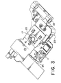
- Fig. 3 is a perspective view of an optical pickup according to one embodiment of this invention;
- Fig. 4 is a perspective view of an objective lens and a lens holder in the optical pickup illustrated in Fig. 3 before they are coupled to each other; and
- Fig. 5 is an enlarged sectional view of a part of the objective lens and the lens holder illustrated in Fig. 4 after they are coupled to each other.
-
- Referring to Fig. 2, description will be made of a general structure of an optical pickup.
- The optical pickup illustrated in the figure is adapted to be used in an optical disk drive mounted to an electronic apparatus such as a personal computer. The optical pickup comprises as a light emitting element a laser diode 11 which is a semiconductor laser for generating a laser beam. The laser beam emitted from the laser diode 11 passes through a diffraction grating 12 to be incident to a
beam splitter 13. The laser beam is split and branched by thebeam splitter 13. Specifically, a part of the laser beam is incident to amonitor 14 having a photo diode while the other part of the laser beam passes through acollimate lens 15, aturning mirror 16, and anobjective lens 17 to irradiate anoptical disk 18. Themonitor 14 detects the intensity of the laser beam. The detected intensity is used to control driving of the laser diode 11. Thus, by the use of the laser beam emitted from the laser diode 11, data can be recorded in theoptical disk 18. - On the other hand, a reflected beam from the
optical disk 18 passes through theobjective lens 17, theturning mirror 16, thecollimate lens 15, thebeam splitter 13, and asensor lens 19 to be incident to aphoto diode 21 as a light-receiving element. Thus, by the use of the laser beam emitted from the laser diode 11, the data recorded in theoptical disk 18 can be reproduced with reference to an electric signal produced by thephoto diode 21. - Referring to Fig. 3 in addition to Fig. 2, the optical pickup will be described in greater detail.
- Herein, various optical elements, such as the
beam splitter 13, thecollimate lens 15, theturning mirror 16, and theobjective lens 17, arranged in a path of the laser beam are collectively called an optical system. The optical system, the laser diode 11, themonitor 14, and thephoto diode 21 are assembled in anoptical base 22 as a housing of the device. Theoptical base 22 is mounted to the optical disk drive to be movable along a guide shaft (not shown) which is provided to the optical disk drive and slidably inserted through aguide hole 23. The laser diode 11 is fixed to a laserdiode fixing portion 24 of theoptical base 22. Theobjective lens 17 is fixedly held by alens holder 25 movably held by theoptical base 22. - Referring to Fig. 4, description will be made in detail of a structure and a method for fixedly connecting or bonding the
optical lens 17 to thelens holder 25 in the optical pickup illustrated in Fig. 3. In Fig. 4, only a part of thelens holder 25, i.e., a part for holding theobjective lens 17 is illustrated. - The
objective lens 17 is made of a transparent resin material and has aflange 26 formed at its outer peripheral edge. Theflange 26 has a surface (lower surface in the figure) faced to thelens holder 17 and provided with fourprotrusions 27 formed at four positions equiangularly spaced in a circumferential direction of theobjective lens 17. Each of theprotrusions 27 extends in a radial direction of theobjective lens 17. All of theprotrusions 27 are substantially equal in size to one another. - On the other hand, the
lens holder 25 has a through-hole 28 for passing the laser beam and astepped portion 29 for receiving theobjective lens 17. Thestepped portion 29 has amounting surface 31 provided with fourrecesses 32 formed at positions corresponding to theprotrusions 27 of theobjective lens 17, i.e., at four positions equiangularly-spaced in a circumferential direction of themounting surface 31, respectively. - Referring to Fig. 5, the
objective lens 17 is coupled to thelens holder 25. Each of theprotrusions 27 extends in the radial direction and forms a triangle in a section taken along a plane perpendicular to the radial direction. The triangle may be an equilateral triangle or an isosceles triangle. Each of theprotrusions 27 has a tip portion facing the mountingsurface 31. The triangle has an angle preferably between 60 and 90 degrees at the tip portion. - Each
recess 32 has a depth smaller than the height of eachprotrusion 27 so that, when theprotrusion 27 of theobjective lens 17 is disposed in therecess 32, a gap of about 0.5mm is formed between the mountingsurface 31 and theflange 26. Therecess 32 has a width (length in the circumferential direction) determined, taking its depth (length in the radial direction of the through·hole 28) into consideration, so that a part of theprotrusion 27 is not extruded or protruded from therecess 32 when theprotrusion 27 is welded to thelens holder 25 as will later be described. Thus, the width of therecess 32 is determined so that the volume of therecess 32 is at least greater than the volume of theprotrusion 27. - Next, description will be made of a method of fusing the
objective lens 17 to thelens holder 25. Herein, use is made of a so-called energy-direct-joint method of utilizing ultrasonic waves. - At first, the
objective lens 17 is fitted to the steppedportion 29 of the lens holder so that theprotrusions 27 are placed in therecesses 32, respectively. At this time, at least a part of theflange 26 of theobjective lens 17 is disposed on the steppedportion 29 so that theobjective lens 17 is positioned. - Next, a horn of an ultrasonic welder (not shown) is pressed against the
flange 26 of theobjective lens 17 on the side opposite to theprotrusions 27 and ultrasonic vibration is generated under pressure. By a complex action of the pressure and the ultrasonic vibration, theprotrusions 27 are melted so that theobjective lens 17 is welded to thelens holder 25. The bonding strength between theobjective lens 17 and thelens holder 25 bonded in the above-mentioned manner is strong as compared with the case where an adhesive is used. Furthermore, according to this method, no adverse affects result, such as adhesive attaching to an effective part of theobjective lens 17. According to this method, theobjective lens 17 can be more easily and quickly bonded to thelens holder 25 as compared with the case where the adhesive is used. In addition, an adhesive-applying portion for escaping adhesive is unnecessary, so that the lens holder can be reduced in size. - Although this invention has been described in conjunction with the preferred embodiment thereof, this invention is not restricted to the foregoing embodiment. For example, the number of the protrusions is equal to four in the foregoing embodiment. However, the number of protrusions may be any desired number not smaller than three. The foregoing embodiment is directed to the objective lens. However, this invention is similarly applicable to various other lenses, such a collimate lens. Furthermore, this invention is applicable not only to the optical pickup but also to bonding of the lens and the lens holder in various other fields.
- Each feature disclosed in this specification (which term includes the claims) and/or shown in the drawings may be incorporated in the invention independently of other disclosed and/or illustrated features.
- The text of the abstract filed herewith is repeated here as part of the specification.
- In a structure for connecting a lens (17) to a lens holder (25) having a mounting surface (31), the lens has a flange (26) mountable on the mounting surface. The flange has a particular surface faced toward the mounting surface and at least three protrusions (27) on the particular surface. The mounting surface has a plurality of recesses (32) formed at positions corresponding to the protrusions. Each of the recesses has a depth smaller than a height of a corresponding one of the protrusions and a volume greater than that of the corresponding protrusion. The protrusions are placed in the respective recesses, and may be welded to the lens holder by ultrasonic means.
Claims (15)
- A connecting structure for connecting a lens to a lens holder, said structure comprising a mounting surface provided on the lens holder and a flange provided on said lens and mountable on said mounting surface, wherein said flange has a particular surface for presenting to said mounting surface and at least three protrusions on said particular surface, said mounting surface having a plurality of recesses formed at positions corresponding to said protrusions, each of said recesses having a depth smaller than a height of a corresponding one of said protrusions and a volume greater than that of said corresponding protrusions, said protrusions each being positionable in a respective recess.
- The structure according to claim 1, wherein said protrusions are welded to said lens holder.
- The structure according to claim 1 or 2, wherein each of said protrusions extends in a radial direction of said lens and forms a triangle in a section taken along a plane perpendicular to said radial direction.
- The structure according to claim 3, wherein said triangle is an equilateral triangle.
- The structure according to claim 3, wherein said triangle is an isosceles triangle.
- The structure according to claim 3, wherein each of said protrusions has a tip portion facing said mounting surface, said triangle having an angle between 60 and 90 degrees at said tip portion.
- A method of connecting a lens to a lens holder having a mounting surface, said lens having a flange which is mountable on said mounting surface and has a particular surface for presenting to said mounting surface, the method comprising the steps of:providing said particular surface with at least three protrusions;providing said mounting surface with recesses formed at positions corresponding to said protrusions, each of said recesses having a depth smaller than a height of a corresponding one of said protrusions and a volume greater than that of said corresponding protrusion;facing said particular surface to said mounting surface so that said protrusions are received in said respective recesses.
- The method according to claim 7, further comprising the step of:welding said protrusions to said lens holder by the use of an ultrasonic welder.
- The method according to claim 7 or 8, wherein the lens is a resin lens.
- The method according to claim 7, 8 or 9, wherein each of said protrusions extends in a radial direction of said lens and forms a triangle in a section taken along a plane perpendicular to said radial direction.
- The method according to claim 10, wherein said triangle is an equilateral triangle.
- The method according to claim 10, wherein said triangle is an isosceles triangle.
- The method according to claim 10, wherein each of said protrusions has a tip portion facing said mounting surface, said triangle having an angle between 60 and 90 degrees at said tip portion.
- An optical pickup comprising a lens and a lens holder, said lens holder having a mounting surface and said lens having a flange mounted on said mounting surface, wherein said flange has a particular surface faced toward said mounting surface and at least three protrusions on said particular surface, said mounting surface having a plurality of recesses formed at positions corresponding to said protrusions, each of said recesses having a depth smaller than a height of a corresponding one of said protrusions and a volume greater than that of said corresponding protrusions, said protrusions each being positioned in a respective recess.
- The optical pickup according to claim 14, wherein said lens is a resin lens.
Applications Claiming Priority (2)
| Application Number | Priority Date | Filing Date | Title |
|---|---|---|---|
| JP2001259115 | 2001-08-29 | ||
| JP2001259115A JP2003066301A (en) | 2001-08-29 | 2001-08-29 | Lens and lens holder joining structure and joining method |
Publications (1)
| Publication Number | Publication Date |
|---|---|
| EP1288692A1 true EP1288692A1 (en) | 2003-03-05 |
Family
ID=19086537
Family Applications (1)
| Application Number | Title | Priority Date | Filing Date |
|---|---|---|---|
| EP02256001A Withdrawn EP1288692A1 (en) | 2001-08-29 | 2002-08-29 | Structure for connecting a lens to a lens holder without using an adhesive |
Country Status (4)
| Country | Link |
|---|---|
| US (1) | US20030043728A1 (en) |
| EP (1) | EP1288692A1 (en) |
| JP (1) | JP2003066301A (en) |
| CN (1) | CN1407362A (en) |
Cited By (5)
| Publication number | Priority date | Publication date | Assignee | Title |
|---|---|---|---|---|
| GB2395459A (en) * | 2002-09-25 | 2004-05-26 | Swintex | Bonding articles with complementary alignment features |
| WO2007033860A1 (en) * | 2005-09-20 | 2007-03-29 | Robert Bosch Gmbh | Method for mounting and alignment of an electro-optical apparatus and measuring device mounted and aligned according to a method of this type |
| US7535663B2 (en) | 2004-12-21 | 2009-05-19 | Ionosep X L.L.C. | Optical pickup actuator |
| EP1930845A3 (en) * | 2006-12-08 | 2009-10-14 | Millipore Corporation | Method and device for mounting a wireless electronic component to a surface |
| CN104321678A (en) * | 2012-02-22 | 2015-01-28 | 柯尼卡美能达株式会社 | Method for manufacturing integrated lens barrel type lens |
Families Citing this family (26)
| Publication number | Priority date | Publication date | Assignee | Title |
|---|---|---|---|---|
| JP2003059064A (en) * | 2001-08-21 | 2003-02-28 | Mitsumi Electric Co Ltd | Laser diode fixing method |
| EP1561140A1 (en) * | 2002-11-11 | 2005-08-10 | Cube Optics AG | Support element for mounting optical elements and method for production of such a support element |
| JP2004297467A (en) * | 2003-03-27 | 2004-10-21 | Minebea Co Ltd | Speaker and manufacturing method thereof |
| DE102004017551A1 (en) * | 2004-04-07 | 2005-10-27 | Deutsche Thomson-Brandt Gmbh | Apparatus for reading and / or writing to optical recording media |
| EP1587077A1 (en) * | 2004-04-15 | 2005-10-19 | Deutsche Thomson-Brandt Gmbh | Device for reproducing and/or recording optical recording media |
| JP4566613B2 (en) * | 2004-04-28 | 2010-10-20 | キヤノン株式会社 | Lens fixing method |
| JP4574233B2 (en) * | 2004-06-02 | 2010-11-04 | キヤノン株式会社 | Lens fixing method |
| JP4779315B2 (en) * | 2004-06-29 | 2011-09-28 | コニカミノルタオプト株式会社 | Lens unit manufacturing method |
| CN100389461C (en) * | 2004-11-12 | 2008-05-21 | 鸿富锦精密工业(深圳)有限公司 | Combination of objective lens and its holder and optical pickup device |
| US8259401B2 (en) * | 2004-11-19 | 2012-09-04 | Eastman Kodak Company | Castellated optical mounting structure |
| JP4610319B2 (en) * | 2004-12-17 | 2011-01-12 | セイコープレシジョン株式会社 | Driving force transmission mechanism and imaging apparatus |
| JP5003059B2 (en) * | 2006-08-21 | 2012-08-15 | 株式会社ニコン | Optical module and manufacturing method thereof |
| CN101135760B (en) * | 2006-08-30 | 2010-09-29 | 鸿富锦精密工业(深圳)有限公司 | Lens module and assembly method thereof |
| KR100843407B1 (en) * | 2006-10-10 | 2008-07-04 | 삼성전기주식회사 | Lens barrel of camera module and laser device to assemble it |
| DE102006050653A1 (en) | 2006-10-24 | 2008-04-30 | Carl Zeiss Smt Ag | Method for connecting an optical element with a fitting on at least one connecting site used in semiconductor lithography comprises indirectly or directly positioning the element and the fitting during connection using a support element |
| JP4835591B2 (en) * | 2007-12-27 | 2011-12-14 | 船井電機株式会社 | Optical pickup |
| CN101738821B (en) * | 2008-11-20 | 2012-06-13 | 深圳富泰宏精密工业有限公司 | Portable electronic device with view-finder module |
| US8174949B2 (en) * | 2009-07-02 | 2012-05-08 | Lsi Corporation | Systems and methods for format efficient timing recovery in a read channel |
| CN101957491A (en) * | 2010-08-24 | 2011-01-26 | 亚泰影像科技股份有限公司 | Method for fixing lens group |
| US9784939B2 (en) * | 2014-02-03 | 2017-10-10 | Robert S. Hodge | Optical retaining device |
| JP2015187624A (en) * | 2014-03-26 | 2015-10-29 | ウシオ電機株式会社 | Optical member and manufacturing method thereof |
| JP6859048B2 (en) | 2016-08-22 | 2021-04-14 | オリンパス株式会社 | Lens holding method, lens assembly manufacturing method, and lens assembly |
| CN108469662B (en) * | 2017-02-23 | 2020-10-27 | 玉晶光电(厦门)有限公司 | Optical lens, assembling method thereof and lens barrel |
| CN108391038B (en) * | 2018-04-24 | 2019-06-04 | Oppo广东移动通信有限公司 | Electronic device and camera assembly thereof |
| DE102018215030A1 (en) | 2018-09-04 | 2020-03-05 | Carl Zeiss Meditec Ag | Lens element and contact device for an ophthalmological laser therapy system |
| JP7270163B2 (en) * | 2019-08-08 | 2023-05-10 | パナソニックIpマネジメント株式会社 | Lens holding structure and illumination device |
Citations (3)
| Publication number | Priority date | Publication date | Assignee | Title |
|---|---|---|---|---|
| DE1629263A1 (en) * | 1966-09-03 | 1971-01-21 | Agfa Gevaert Ag | Method for welding a plastic lens with a plastic frame |
| EP0435525A2 (en) * | 1989-12-27 | 1991-07-03 | Nestle S.A. | Multifocal diffractive ophthalmic lens and method of manufacture |
| JPH07272302A (en) * | 1994-03-31 | 1995-10-20 | Matsushita Electric Ind Co Ltd | Objective lens device |
-
2001
- 2001-08-29 JP JP2001259115A patent/JP2003066301A/en not_active Withdrawn
-
2002
- 2002-08-28 US US10/229,467 patent/US20030043728A1/en not_active Abandoned
- 2002-08-29 EP EP02256001A patent/EP1288692A1/en not_active Withdrawn
- 2002-08-29 CN CN02141978A patent/CN1407362A/en active Pending
Patent Citations (3)
| Publication number | Priority date | Publication date | Assignee | Title |
|---|---|---|---|---|
| DE1629263A1 (en) * | 1966-09-03 | 1971-01-21 | Agfa Gevaert Ag | Method for welding a plastic lens with a plastic frame |
| EP0435525A2 (en) * | 1989-12-27 | 1991-07-03 | Nestle S.A. | Multifocal diffractive ophthalmic lens and method of manufacture |
| JPH07272302A (en) * | 1994-03-31 | 1995-10-20 | Matsushita Electric Ind Co Ltd | Objective lens device |
Non-Patent Citations (4)
| Title |
|---|
| AGEORGES C ET AL: "Advances in fusion bonding techniques for joining thermoplastic matrix composites: a review", COMPOSITES PART A: APPLIED SCIENCE AND MANUFACTURING, ELSEVIER SCIENCE PUBLISHERS B.V., AMSTERDAM, NL, vol. 32, no. 6, 1 June 2001 (2001-06-01), pages 839 - 857, XP004232559, ISSN: 1359-835X * |
| LAND W: "EINFLUSS DER FUEGENAHTGESTALTUNG AUF DAS SCHWEISSVERHALTEN", PLASTVERARBEITER, ZECHNER UND HUETHIG VERLAG GMBH. SPEYER/RHEIN, DE, vol. 34, no. 9, 1 September 1983 (1983-09-01), pages 798 - 800, XP000677089, ISSN: 0032-1338 * |
| MCCARTHY, L.: "Part design is critical for good welds", PLASTICS WORLD, vol. 48, no. 7, June 1990 (1990-06-01), pages 62 - 67, XP001119210 * |
| PATENT ABSTRACTS OF JAPAN vol. 1996, no. 02 29 February 1996 (1996-02-29) * |
Cited By (12)
| Publication number | Priority date | Publication date | Assignee | Title |
|---|---|---|---|---|
| GB2395459A (en) * | 2002-09-25 | 2004-05-26 | Swintex | Bonding articles with complementary alignment features |
| GB2395459B (en) * | 2002-09-25 | 2005-11-23 | Swintex | Method of manufacture of a plastics construction product and plastics construction product |
| US7535663B2 (en) | 2004-12-21 | 2009-05-19 | Ionosep X L.L.C. | Optical pickup actuator |
| US7751133B2 (en) | 2004-12-21 | 2010-07-06 | In Ho Choi | Optical pickup actuator |
| US7986474B2 (en) | 2004-12-21 | 2011-07-26 | Ionosep X Holdings L.L.C. | Optical pickup actuator |
| US8570674B2 (en) | 2004-12-21 | 2013-10-29 | Ionosep X Holdings L.L.C. | Optical pickup actuator |
| WO2007033860A1 (en) * | 2005-09-20 | 2007-03-29 | Robert Bosch Gmbh | Method for mounting and alignment of an electro-optical apparatus and measuring device mounted and aligned according to a method of this type |
| EP1930845A3 (en) * | 2006-12-08 | 2009-10-14 | Millipore Corporation | Method and device for mounting a wireless electronic component to a surface |
| US7892471B2 (en) | 2006-12-08 | 2011-02-22 | Millipore Corporation | Wireless enabled device |
| US8100585B2 (en) | 2006-12-08 | 2012-01-24 | Millipore Corporation | Wireless enabled device |
| CN104321678A (en) * | 2012-02-22 | 2015-01-28 | 柯尼卡美能达株式会社 | Method for manufacturing integrated lens barrel type lens |
| CN104321678B (en) * | 2012-02-22 | 2016-10-12 | 柯尼卡美能达株式会社 | The manufacture method of the one-piece type lens of lens barrel |
Also Published As
| Publication number | Publication date |
|---|---|
| US20030043728A1 (en) | 2003-03-06 |
| JP2003066301A (en) | 2003-03-05 |
| CN1407362A (en) | 2003-04-02 |
Similar Documents
| Publication | Publication Date | Title |
|---|---|---|
| US20030043728A1 (en) | Structure for connecting a lens to a lens holder without using an adhesive | |
| US7359308B2 (en) | Fixing structure for optical element and optical head device | |
| US7246364B2 (en) | Optical pickup device | |
| JP2962923B2 (en) | Light source device | |
| JP2004158784A (en) | Light source device | |
| JP4371064B2 (en) | Mounting structure of the laser holder to the base member | |
| JP3528835B2 (en) | Defocus adjustment mechanism of optical pickup device | |
| JP2002100053A (en) | Pickup device for disk player | |
| JP2000215466A (en) | Optical pickup | |
| JP2008171498A (en) | Optical head device | |
| JPH05181026A (en) | Optical integrated circuit and manufacturing method thereof | |
| KR100346291B1 (en) | An optical pick up | |
| JP2004206760A (en) | Optical head | |
| EP1004115A2 (en) | Optical pickup apparatus, holder and method of producing optical pickup apparatus | |
| KR200156682Y1 (en) | Optical detector fixing device for optical pickup | |
| JP3518904B2 (en) | Optical pickup | |
| KR100463421B1 (en) | Fixing method of beam splitter for optical pick-up | |
| JPH06203388A (en) | Fixing device for photodetector and optical head equipped with this fixing device | |
| JP3087144B2 (en) | Objective lens actuator | |
| JPH08221797A (en) | Optical parts mounting structure for optical pickup | |
| JP2010277680A (en) | OPTICAL DEVICE, OPTICAL PICKUP DEVICE, OPTICAL DISK DRIVE DEVICE, AND OPTICAL DEVICE MANUFACTURING METHOD | |
| JPH0793780A (en) | Optical device | |
| JP2005339709A (en) | Structure for mounting semiconductor conversion element of optical pickup | |
| JP2000285495A (en) | Disk recording and playback device | |
| JPH06274899A (en) | Fixing device for photodetector and optical head including this fixing device |
Legal Events
| Date | Code | Title | Description |
|---|---|---|---|
| PUAI | Public reference made under article 153(3) epc to a published international application that has entered the european phase |
Free format text: ORIGINAL CODE: 0009012 |
|
| AK | Designated contracting states |
Kind code of ref document: A1 Designated state(s): AT BE BG CH CY CZ DE DK EE ES FI FR GB GR IE IT LI LU MC NL PT SE SK TR Designated state(s): AT BE BG CH CY CZ DE DK EE ES FI FR GB GR IE IT LI LU MC NL PT SE SK TR |
|
| AX | Request for extension of the european patent |
Extension state: AL LT LV MK RO SI |
|
| AKX | Designation fees paid |
Designated state(s): DE FR GB |
|
| STAA | Information on the status of an ep patent application or granted ep patent |
Free format text: STATUS: THE APPLICATION IS DEEMED TO BE WITHDRAWN |
|
| 18D | Application deemed to be withdrawn |
Effective date: 20030906 |