EP1288573A2 - Glow plug - Google Patents
Glow plug Download PDFInfo
- Publication number
- EP1288573A2 EP1288573A2 EP02016926A EP02016926A EP1288573A2 EP 1288573 A2 EP1288573 A2 EP 1288573A2 EP 02016926 A EP02016926 A EP 02016926A EP 02016926 A EP02016926 A EP 02016926A EP 1288573 A2 EP1288573 A2 EP 1288573A2
- Authority
- EP
- European Patent Office
- Prior art keywords
- rear end
- ceramic heater
- connecting member
- metallic sleeve
- layer
- Prior art date
- Legal status (The legal status is an assumption and is not a legal conclusion. Google has not performed a legal analysis and makes no representation as to the accuracy of the status listed.)
- Granted
Links
Images

Classifications
-
- F—MECHANICAL ENGINEERING; LIGHTING; HEATING; WEAPONS; BLASTING
- F23—COMBUSTION APPARATUS; COMBUSTION PROCESSES
- F23Q—IGNITION; EXTINGUISHING-DEVICES
- F23Q7/00—Incandescent ignition; Igniters using electrically-produced heat, e.g. lighters for cigarettes; Electrically-heated glowing plugs
- F23Q7/001—Glowing plugs for internal-combustion engines
-
- H—ELECTRICITY
- H05—ELECTRIC TECHNIQUES NOT OTHERWISE PROVIDED FOR
- H05B—ELECTRIC HEATING; ELECTRIC LIGHT SOURCES NOT OTHERWISE PROVIDED FOR; CIRCUIT ARRANGEMENTS FOR ELECTRIC LIGHT SOURCES, IN GENERAL
- H05B3/00—Ohmic-resistance heating
- H05B3/10—Heating elements characterised by the composition or nature of the materials or by the arrangement of the conductor
- H05B3/12—Heating elements characterised by the composition or nature of the materials or by the arrangement of the conductor characterised by the composition or nature of the conductive material
- H05B3/14—Heating elements characterised by the composition or nature of the materials or by the arrangement of the conductor characterised by the composition or nature of the conductive material the material being non-metallic
- H05B3/141—Conductive ceramics, e.g. metal oxides, metal carbides, barium titanate, ferrites, zirconia, vitrous compounds
-
- H—ELECTRICITY
- H05—ELECTRIC TECHNIQUES NOT OTHERWISE PROVIDED FOR
- H05B—ELECTRIC HEATING; ELECTRIC LIGHT SOURCES NOT OTHERWISE PROVIDED FOR; CIRCUIT ARRANGEMENTS FOR ELECTRIC LIGHT SOURCES, IN GENERAL
- H05B2203/00—Aspects relating to Ohmic resistive heating covered by group H05B3/00
- H05B2203/027—Heaters specially adapted for glow plug igniters
Definitions
- a glow plug is widely used for the preheating of a diesel engine, which comprises a metallic sleeve, a rod-shaped ceramic heater disposed in the metallic sleeve with a front end portion thereof protruded from the metallic sleeve and a metallic shell fitted onto the metallic sleeve by e.g. brazing.
- the ceramic heater generally includes an insulating ceramic substrate, a heating resistor embedded in a front end portion of the ceramic substrate and a pair of electric conductors (such as high-melting lead wires made of e.g. conductive ceramic or tungsten) embedded in the ceramic substrate and electrically connected to the heating resistor.
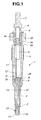
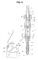
- the glow plug 1 comprises a rod-shaped ceramic heater 2, a metallic sleeve 3 circumferentially surrounding the ceramic heater 2 with a front end portion of the ceramic heater 2 protruded from the metallic sleeve 3, a cylindrical metallic shell 4 retaining therein a rear end portion of the metallic sleeve 3, a metallic central electrode 6 partly disposed in a rear portion of the metallic shell 4 for power supply to the ceramic heater 2, and a lead wire 17 through which the ceramic heater 2 and the central electrode 6 are electrically connected to each other.
- a threaded portion 5 is formed on an outer circumferential surface of the metallic shell 4 so as to mount the glow plug 1 in a cylinder head (not shown).
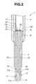
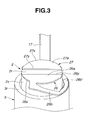
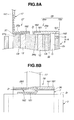
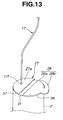
- the glow plug 1 further comprises a first connecting member 26 through which the exposed rear end portion 12r of the conductor 12 is electrically connected to a rear end face 3r of the metallic sleeve 3.
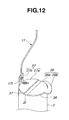
- the glow plug 1 also comprises a second connecting member 27 through which the exposed rear end portion 13r of the conductor 13 is electrically connected to a front end portion of the lead wire 17, although the rear end portion 13r of the conductor 13 may be directly connected to the lead wire 17.
- the first and second connecting members 26 and 27 are provided so as not to have a direct electrical connection therebetween.
- first and second connecting members 26 and 27 are formed into a plate.
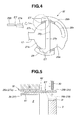
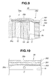
- the first connecting member 26 has a front surface 26q connected via the brazing layer 36 with the part of the rear end surface 2r of the ceramic heater 2 including an exposed surface of the rear end portion 12r of the electric conductor 12
- the second connecting member 27 has a front surface 27q connected via the brazing layer 37 with the part of the rear end surface 2r of the ceramic heater 2 including an exposed surface of the rear end portion 13r of the electric conductor 13.
- This makes it possible to secure larger joint surfaces between the ceramic heater 2 and each of the first and second connecting members 26 and 27, between the electric conductor 12 and the first connecting member 26 and between the electric conductor 13 and the second connecting member 27 and thereby possible to increase joint strengths therebetween.
- the first and second connecting members 26 and 27 can be easily joined to the rear end surface 2r of the ceramic heater 2 by brazing in such a structure, and much expense in time and effort is not needed to provide the first and second connecting members 26 and 27.
- the second connecting member 27 also has a conductive portion 27a joined to the rear end surface 2r of the ceramic heater 2 via the brazing layer 37, as shown in FIG. 3.
Landscapes
- Engineering & Computer Science (AREA)
- Chemical & Material Sciences (AREA)
- Combustion & Propulsion (AREA)
- Mechanical Engineering (AREA)
- General Engineering & Computer Science (AREA)
- Ceramic Engineering (AREA)
- Resistance Heating (AREA)
Abstract
Description
Claims (19)
- A glow plug (1) comprising:a ceramic heater (2) having an insulating ceramic substrate (14), a heating resistor (11) embedded in a front end portion of the ceramic substrate (14), and a pair of first and second electric conductors (12, 13) embedded in the ceramic substrate (14) and electrically connected at front end portions thereof to the heating resistor (11); anda metallic sleeve (3) circumferentially surrounding the ceramic heater (2) with a front end portion of the ceramic heater (2) protruded from the metallic sleeve (3),the first electric conductor (12) having a rear end portion (12r) exposed at a rear end surface (2r) of the ceramic heater (2) and electrically connected to the metallic sleeve (3).
- A glow plug (1) according to Claim 1, wherein the ceramic heater (2) is disposed in the metallic sleeve (3) with a rear end portion of the ceramic heater (2) protruded from the metallic sleeve (3).
- A glow plug (1) according to Claim 1 or 2, further comprising a first connecting member (26) through which the exposed rear end portion (12r) of the first electric conductor (12) is electrically connected to a rear end face (3r) of the metallic sleeve (3).
- A glow plug (1) according to Claim 3, wherein the first connecting member (26) has a first conductive portion (26a) joined to the rear end surface (2r) of the ceramic heater (2) and a second conductive portion (26b) formed integrally with the first conductive portion (26a) so as to extend to the metallic sleeve (3) and joined at a end (26b') thereof to the rear end face (3) of the metallic sleeve (3), and the end (26b') of the second conductive portion (26b) is shaped to fit with the rear end face (3r) of the metallic sleeve (3).
- A glow plug (1) according to Claim 3 or 4, wherein the first connecting member (26) is joined to the rear end surface (2r) of the ceramic heater (2) via a brazing layer (36) made of an activated brazing material.
- A glow plug (1) according to Claim 5, wherein the first connecting member (26) is formed into a plate and has a low-expansion metal layer (62) formed in a rear surface (26p) thereof so as to correspond in position to the brazing layer (36) while being in contact with the brazing layer (36) at a front surface (26q) thereof, and the low-expansion metal layer (62) is made of a metal having a lower coefficient of linear expansion than the activated brazing material.
- A glow plug (1) according to Claim 6, wherein the first connecting member (26) further has a soft metal layer (61) formed in the front surface (26q) thereof so as to be in contact with the brazing layer (36), and the soft metal layer (61) is made of a metal softer than the metal of the low-expansion metal layer (62).
- A glow plug (1) according to Claim 7, wherein the low-expansion metal layer (62) and the soft metal layer (61) are clad with each other at least in part of the first connecting member (26).
- A glow plug (1) according to any one of Claims 5 to 7, wherein the first connecting member (26) includes an end portion (26b) joined to the rear end face (3r) of the metallic sleeve (3), and the end portion (26b) of the first connecting member (26) is made of a metal having a lower coefficient of linear expansion than the activated brazing material.
- A glow plug (1) according to any one of Claims 3 to 5, wherein the first connecting member (26) is formed into a plate and has first and second layers (126, 127) formed in a thickness direction thereof, the first connecting member (26) is bent so that the first layer (161) is joined to the rear end surface (2r) of the ceramic heater (2) via the brazing layer (36) and the second layer (162) is joined to the rear end face (3r) of the metallic sleeve (3), and the first layer (161) is made of a material having a higher coefficient of linear expansion than a material for the second layer (162).
- A glow plug (1) according to any one of Claims 3 to 5, wherein the first connecting member (26) includes an end portion (26b) joined to the rear end face (3r) of the metallic sleeve (3), the end portion (26b) of the first connecting member (26) has a first layer (261), a second layer (262) on a rear side of the first layer (261) and a third layer (263) on a front side of the first layer (261), and the first layer (261) is made of a material having a higher coefficient of linear expansion than materials for the second and third layers (262, 263).
- A glow plug (1) according to any one of Claims 1 to 11, the ceramic heater (2) is disposed in the metallic sleeve (3) with a clearance (G) between an outer circumferential surface (2s) of the ceramic heater (2) and an inner circumferential surface of a rear end portion of the metallic sleeve (3).
- A glow plug (1) according to Claim 12, wherein the clearance (G) is larger than or equal to 0.1 mm.
- A glow plug (1) comprising:a ceramic heater (2) having an insulating ceramic substrate (14), a heating resistor (11) embedded in a front end portion of the ceramic substrate (14), and a pair of first and second electric conductors (12, 13) embedded in the ceramic substrate (14) and electrically connected at front end portions thereof to the heating resistor (11);a metallic sleeve (3) circumferentially surrounding the ceramic heater (2) with a front end portion of the ceramic heater (2) protruded from the metallic sleeve (3);a metallic shell (4) fitted onto the metallic sleeve (3); anda central electrode (6) disposed in a rear portion of the metallic shell (4),the first and second electric conductors (12, 13) having rear end portions (12r, 13r) exposed at a rear end surface (2r) of the ceramic heater (3) and electrically connected to the metallic sleeve (3) and the central electrode (6), respectively.
- A glow plug (1) according to Claim 14, further comprising:a first connecting member (26) through which the rear end portion (12r) of the first electric conductor (12) is electrically connected to a rear end face (3r) of the metallic sleeve (3); anda second connecting member (27) through which the rear end portion (13r) of the second electric conductor (13) is electrically connected to the central electrode (6).
- A glow plug (1) according to Claim 15, wherein the first and second connecting members (26, 27) are formed into one piece and separated from each other after joined to the rear end surface (2r) of the ceramic heater (2).
- A glow plug (1) according to Claim 15, further comprising a lead wire (17) through which the second connecting member (27) and the central electrode (6) are electrically connected to each other,
wherein the first connecting member (26) includes a joint portion (26b) having a surface layer welded to the rear end face (3r) of the metallic sleeve (3), the second connecting member (27) includes a joint portion (27a, 27b) having a surface layer to which the lead wire (17) is welded, and the surface layers of the joint portions (26b, 27a; or 26b, 27b) of the first and second connecting members (26, 27) are made of the same material. - A glow plug (1) according to Claim 17, wherein the joint portion (27b) of the second connecting member (27) is protruded rearwardly.
- A glow plug (1) according to any one of Claims 15 to 18, wherein the first and second connecting members (26, 27) are joined to the rear end surface (2r) of the ceramic heater (2) via brazing layers (36, 37) made of an activated brazing material.
Applications Claiming Priority (4)
| Application Number | Priority Date | Filing Date | Title |
|---|---|---|---|
| JP2001258074 | 2001-08-28 | ||
| JP2001258074 | 2001-08-28 | ||
| JP2001367350A JP2003148731A (en) | 2001-08-28 | 2001-11-30 | Glow plug |
| JP2001367350 | 2001-11-30 |
Publications (3)
| Publication Number | Publication Date |
|---|---|
| EP1288573A2 true EP1288573A2 (en) | 2003-03-05 |
| EP1288573A3 EP1288573A3 (en) | 2006-09-13 |
| EP1288573B1 EP1288573B1 (en) | 2008-11-12 |
Family
ID=26621124
Family Applications (1)
| Application Number | Title | Priority Date | Filing Date |
|---|---|---|---|
| EP02016926A Expired - Lifetime EP1288573B1 (en) | 2001-08-28 | 2002-07-31 | Glow plug |
Country Status (4)
| Country | Link |
|---|---|
| US (1) | US6689990B2 (en) |
| EP (1) | EP1288573B1 (en) |
| JP (1) | JP2003148731A (en) |
| DE (1) | DE60229817D1 (en) |
Cited By (3)
| Publication number | Priority date | Publication date | Assignee | Title |
|---|---|---|---|---|
| WO2008110496A1 (en) * | 2007-03-15 | 2008-09-18 | Robert Bosch Gmbh | Seal for a glow plug |
| US20100288747A1 (en) * | 2007-10-29 | 2010-11-18 | Kyocera Corporation | Ceramic heater and glow plug provided therewith |
| US20110114622A1 (en) * | 2008-02-20 | 2011-05-19 | Ngk Spark Plug Co., Ltd. | Ceramic heater and glow plug |
Families Citing this family (12)
| Publication number | Priority date | Publication date | Assignee | Title |
|---|---|---|---|---|
| JP3886449B2 (en) * | 2002-12-26 | 2007-02-28 | 日本特殊陶業株式会社 | Glow plug and glow plug mounting structure |
| EP1477740B1 (en) * | 2003-04-07 | 2013-12-25 | Ngk Spark Plug Co., Ltd | Heater |
| DE102006016566B4 (en) * | 2005-09-22 | 2008-06-12 | Beru Ag | Composite conductor, in particular for glow plugs for diesel engines |
| KR101488748B1 (en) * | 2011-01-20 | 2015-02-03 | 쿄세라 코포레이션 | Heater and glow plug provided with same |
| CN103493586B (en) * | 2011-04-27 | 2015-11-25 | 京瓷株式会社 | Heater and glow plug having the heater |
| JP6152469B2 (en) * | 2014-03-27 | 2017-06-21 | ボッシュ株式会社 | Ceramic heater type glow plug |
| WO2015153180A1 (en) | 2014-04-04 | 2015-10-08 | Bloom Energy Corporation | Fuel cell system glow plug and method of forming same |
| US10514017B2 (en) | 2017-03-21 | 2019-12-24 | Pratt & Whitney Canada Corp. | Internal combustion engine with igniter cooling sleeve |
| US11824232B2 (en) | 2017-09-14 | 2023-11-21 | Bloom Energy Corporation | Internal light off mechanism for solid oxide fuel cell system startup using a spark ignitor |
| US10930943B2 (en) | 2018-01-08 | 2021-02-23 | Bloom Energy Corporation | Fuel cell system including inductive heating element and method of using same |
| CN207869432U (en) * | 2018-03-07 | 2018-09-14 | 东莞市国研电热材料有限公司 | A multi-temperature zone ceramic heating element |
| WO2020067508A1 (en) | 2018-09-28 | 2020-04-02 | 京セラ株式会社 | Heater and glow-plug provided therewith |
Family Cites Families (9)
| Publication number | Priority date | Publication date | Assignee | Title |
|---|---|---|---|---|
| US4556780A (en) * | 1983-10-17 | 1985-12-03 | Nippondenso Co., Ltd. | Ceramic heater |
| JPS60114629A (en) * | 1983-11-28 | 1985-06-21 | Jidosha Kiki Co Ltd | Glow plug for diesel engine |
| JPS62141423A (en) | 1985-12-13 | 1987-06-24 | Jidosha Kiki Co Ltd | Glow plug diesel engine |
| JPS6391432A (en) * | 1986-10-03 | 1988-04-22 | Jidosha Kiki Co Ltd | Manufacture of glow plug for diesel engine |
| JPH04143518A (en) * | 1990-10-04 | 1992-05-18 | Ngk Spark Plug Co Ltd | Self-regulative type ceramic glow plug |
| JP3044630B2 (en) * | 1991-02-06 | 2000-05-22 | ボッシュ ブレーキ システム株式会社 | Ceramic heater type glow plug |
| JP3044632B2 (en) * | 1991-02-20 | 2000-05-22 | ボッシュ ブレーキ システム株式会社 | Ceramic heater type glow plug |
| JPH10300085A (en) * | 1997-04-22 | 1998-11-13 | Ngk Spark Plug Co Ltd | Ceramic heater and ceramic glow plug |
| JPH11257659A (en) * | 1998-03-10 | 1999-09-21 | Ngk Spark Plug Co Ltd | Ceramic heater and ceramic glow plug |
-
2001
- 2001-11-30 JP JP2001367350A patent/JP2003148731A/en active Pending
-
2002
- 2002-07-31 DE DE60229817T patent/DE60229817D1/en not_active Expired - Lifetime
- 2002-07-31 EP EP02016926A patent/EP1288573B1/en not_active Expired - Lifetime
- 2002-08-01 US US10/208,794 patent/US6689990B2/en not_active Expired - Fee Related
Cited By (5)
| Publication number | Priority date | Publication date | Assignee | Title |
|---|---|---|---|---|
| WO2008110496A1 (en) * | 2007-03-15 | 2008-09-18 | Robert Bosch Gmbh | Seal for a glow plug |
| US8003917B2 (en) | 2007-03-15 | 2011-08-23 | Robert Bosch Gmbh | Seal for a glow plug |
| US20100288747A1 (en) * | 2007-10-29 | 2010-11-18 | Kyocera Corporation | Ceramic heater and glow plug provided therewith |
| US20110114622A1 (en) * | 2008-02-20 | 2011-05-19 | Ngk Spark Plug Co., Ltd. | Ceramic heater and glow plug |
| US8378273B2 (en) * | 2008-02-20 | 2013-02-19 | Ngk Spark Plug Co., Ltd. | Ceramic heater and glow plug |
Also Published As
| Publication number | Publication date |
|---|---|
| US6689990B2 (en) | 2004-02-10 |
| JP2003148731A (en) | 2003-05-21 |
| EP1288573B1 (en) | 2008-11-12 |
| DE60229817D1 (en) | 2008-12-24 |
| US20030042242A1 (en) | 2003-03-06 |
| EP1288573A3 (en) | 2006-09-13 |
Similar Documents
| Publication | Publication Date | Title |
|---|---|---|
| US8552343B2 (en) | Brazing structure, ceramic heater, and glow plug | |
| EP1288573B1 (en) | Glow plug | |
| JP3816073B2 (en) | Glow plug and method of manufacturing glow plug | |
| US6737612B2 (en) | Ceramic heater and glow plug having the ceramic heater | |
| JP2002270339A (en) | Ceramic heater | |
| JP4677140B2 (en) | Glow plug | |
| EP2296430A2 (en) | Ceramic heater and gas sensor including the same | |
| JP4562315B2 (en) | Ceramic heater, ceramic heater manufacturing method, and glow plug | |
| JP4559671B2 (en) | Glow plug and manufacturing method thereof | |
| JP4672910B2 (en) | Glow plug manufacturing method | |
| JP4434516B2 (en) | Glow plug | |
| JP2003056849A (en) | Glow plug | |
| JP3886684B2 (en) | Ceramic heater | |
| JP2002333136A (en) | Glow plug | |
| JP2003166714A (en) | Glow plug and method for manufacturing glow plug | |
| JP2002299009A (en) | Ceramic heater | |
| JP2002333137A (en) | Glow plug | |
| JP2002349852A (en) | Glow plug and method of manufacturing glow plug | |
| JP4596684B2 (en) | Glow plug | |
| CN112314051B (en) | Heater and glow plug provided with same | |
| JP2002333135A (en) | Glow plug | |
| JPH0439195B2 (en) | ||
| JPH11329801A (en) | Electric resistance element and manufacturing method thereof |
Legal Events
| Date | Code | Title | Description |
|---|---|---|---|
| PUAI | Public reference made under article 153(3) epc to a published international application that has entered the european phase |
Free format text: ORIGINAL CODE: 0009012 |
|
| AK | Designated contracting states |
Kind code of ref document: A2 Designated state(s): AT BE BG CH CY CZ DE DK EE ES FI FR GB GR IE IT LI LU MC NL PT SE SK TR |
|
| AX | Request for extension of the european patent |
Extension state: AL LT LV MK RO SI |
|
| PUAL | Search report despatched |
Free format text: ORIGINAL CODE: 0009013 |
|
| AK | Designated contracting states |
Kind code of ref document: A3 Designated state(s): AT BE BG CH CY CZ DE DK EE ES FI FR GB GR IE IT LI LU MC NL PT SE SK TR |
|
| AX | Request for extension of the european patent |
Extension state: AL LT LV MK RO SI |
|
| 17P | Request for examination filed |
Effective date: 20061004 |
|
| 17Q | First examination report despatched |
Effective date: 20061227 |
|
| AKX | Designation fees paid |
Designated state(s): DE FR GB IT |
|
| GRAP | Despatch of communication of intention to grant a patent |
Free format text: ORIGINAL CODE: EPIDOSNIGR1 |
|
| GRAS | Grant fee paid |
Free format text: ORIGINAL CODE: EPIDOSNIGR3 |
|
| GRAA | (expected) grant |
Free format text: ORIGINAL CODE: 0009210 |
|
| AK | Designated contracting states |
Kind code of ref document: B1 Designated state(s): DE FR GB IT |
|
| REG | Reference to a national code |
Ref country code: GB Ref legal event code: FG4D |
|
| REF | Corresponds to: |
Ref document number: 60229817 Country of ref document: DE Date of ref document: 20081224 Kind code of ref document: P |
|
| PLBE | No opposition filed within time limit |
Free format text: ORIGINAL CODE: 0009261 |
|
| STAA | Information on the status of an ep patent application or granted ep patent |
Free format text: STATUS: NO OPPOSITION FILED WITHIN TIME LIMIT |
|
| 26N | No opposition filed |
Effective date: 20090813 |
|
| GBPC | Gb: european patent ceased through non-payment of renewal fee |
Effective date: 20090731 |
|
| PG25 | Lapsed in a contracting state [announced via postgrant information from national office to epo] |
Ref country code: GB Free format text: LAPSE BECAUSE OF NON-PAYMENT OF DUE FEES Effective date: 20090731 |
|
| PG25 | Lapsed in a contracting state [announced via postgrant information from national office to epo] |
Ref country code: IT Free format text: LAPSE BECAUSE OF FAILURE TO SUBMIT A TRANSLATION OF THE DESCRIPTION OR TO PAY THE FEE WITHIN THE PRESCRIBED TIME-LIMIT Effective date: 20081112 |
|
| PGFP | Annual fee paid to national office [announced via postgrant information from national office to epo] |
Ref country code: FR Payment date: 20140708 Year of fee payment: 13 |
|
| REG | Reference to a national code |
Ref country code: FR Ref legal event code: ST Effective date: 20160331 |
|
| PG25 | Lapsed in a contracting state [announced via postgrant information from national office to epo] |
Ref country code: FR Free format text: LAPSE BECAUSE OF NON-PAYMENT OF DUE FEES Effective date: 20150731 |
|
| PGFP | Annual fee paid to national office [announced via postgrant information from national office to epo] |
Ref country code: DE Payment date: 20170725 Year of fee payment: 16 |
|
| REG | Reference to a national code |
Ref country code: DE Ref legal event code: R119 Ref document number: 60229817 Country of ref document: DE |
|
| PG25 | Lapsed in a contracting state [announced via postgrant information from national office to epo] |
Ref country code: DE Free format text: LAPSE BECAUSE OF NON-PAYMENT OF DUE FEES Effective date: 20190201 |