EP1288529B1 - Fluid transmitting device with lock-up clutch - Google Patents
Fluid transmitting device with lock-up clutch Download PDFInfo
- Publication number
- EP1288529B1 EP1288529B1 EP02018710A EP02018710A EP1288529B1 EP 1288529 B1 EP1288529 B1 EP 1288529B1 EP 02018710 A EP02018710 A EP 02018710A EP 02018710 A EP02018710 A EP 02018710A EP 1288529 B1 EP1288529 B1 EP 1288529B1
- Authority
- EP
- European Patent Office
- Prior art keywords
- clutch
- oil chamber
- lock
- turbine runner
- side cover
- Prior art date
- Legal status (The legal status is an assumption and is not a legal conclusion. Google has not performed a legal analysis and makes no representation as to the accuracy of the status listed.)
- Expired - Fee Related
Links
Images


Classifications
-
- F—MECHANICAL ENGINEERING; LIGHTING; HEATING; WEAPONS; BLASTING
- F16—ENGINEERING ELEMENTS AND UNITS; GENERAL MEASURES FOR PRODUCING AND MAINTAINING EFFECTIVE FUNCTIONING OF MACHINES OR INSTALLATIONS; THERMAL INSULATION IN GENERAL
- F16H—GEARING
- F16H45/00—Combinations of fluid gearings for conveying rotary motion with couplings or clutches
- F16H45/02—Combinations of fluid gearings for conveying rotary motion with couplings or clutches with mechanical clutches for bridging a fluid gearing of the hydrokinetic type
Definitions
- the present invention relates to a fluid transmitting device corresponding to the preamble of claims 1 and 4.
- a conventional fluid transmitting device with a lock-up clutch is known as disclosed in, for example, Japanese Patent Application Laid-open No. 5-296313.
- a dragging-preventing gap is provided between the clutch piston and the side cover in a non-connected state of the lock-up clutch. Therefore, when the lock-up control means is operated to bring the lock-up clutch into a connected state, working oil is more or less leaked from the high-pressure inner oil chamber through the gap into the low-pressure outer oil chamber at an initial stage of the operation of the lock-up control means. This is one factor of the retardation in the operation of the lock-up clutch.
- a seal member is mounted on an outer periphery of the clutch piston to come into a close contact with an inner peripheral surface of the side cover, thereby preventing the leakage of the working oil.
- This fluid transmitting device has the following problems: It is required that a one-way valve is provided in the clutch piston in order to enable the working oil from the outer oil chamber to flow toward the inner oil chamber upon the release of the operation of the lock-up clutch, inevitably leading to an increase in the number of parts and in turn an increase in cost; in addition, the seal member on the outer periphery of the clutch piston always rubs against the inner peripheral surface of the side cover, when the pump impeller and the turbine runner are rotated relative to each other in the non-connected state of the lock-up clutch, so that it is difficult to ensure the durability of the seal member.
- US 6,155,932-A discloses a fluid transmitting device of this type wherein further there is provided a dividing means between turbine runner and clutch piston.
- the dividing means known from this document is a preferably elastic wall dividing the inner oil chamber as discussed above in sub chambers, one being adjacent said turbine runner and the other being adjacent said clutch piston, said dividing wall being mounted to the pump impeller wall and comprising at its radially inner side a seal against the rotating parts.
- This fluid transmitting device thus comprises a number of additional parts.
- connection responsiveness of the lock-up clutch is excellent and moreover a number of parts is small, leading to a lower cost and the durability is high.
- said dividing means is adapted to divide the inner oil chamber into a radially inner and substantial closed primary inner oil chamber section and a radially outer secondary inner oil chambers section when such lock-up control means is operated to earth the clutch piston direction of engagement of the friction engaging means, the pressure in the primary inner oil chamber section and the secondary inner oil chamber section are raised in the named order relative to the outer oil chamber.
- the clutch piston can be first advanced in a direction to operate the friction engaging means by the quick raising of the pressure in the primary inner oil chamber section, thereby inhibiting the leakage of the working oil from the secondary inner oil chamber section to the outer oil chamber.
- the raising of the pressure in the secondary inner oil chamber section can be also hastened, and as a result the raising of the pressures in the primary inner oil chamber section and the secondary inner oil chamber section as a whole can be hastened, whereby the clutch piston can be urged quickly and powerfully toward the side cover to enhance the connection responsiveness of the lock-up clutch.
- the urging force on the clutch piston is sequentially generated in the primary inner oil chamber section and the secondary inner oil chamber section, whereby the shock of the connection of the lock-up clutch can be alleviated.
- the flowing of the working oil from the outer oil chamber to the inner oil chamber can be conducted smoothly without recourse to a one-way valve required in the prior art, and the cooling of the lock-up clutch can be achieved.
- the number of parts can be reduced because no one-way valve is required, to thereby contribute to a reduction of cost.
- a through-bore is provided in the turbine runner to permit the primary inner oil chambers section to communicate with the circulation circuit.
- the pressure in the area of the circulation circuit on the side of the turbine runner is lower, and hence the working oil in the primary inner oil chamber section flows through the through-bore into the circulation circuit to lower the pressure in the primary inner oil chamber section, but the dropping of the pressure in the primary inner chamber section does not involve the secondary inner chamber section, because the through-bore does not communicate with the secondary inner chamber section and moreover, the primary and secondary inner chamber sections are partitioned from each other by the dividing means.
- the secondary inner chamber section is maintained at a relatively high pressure, because it communicates with the outer periphery of the circulation circuit.
- the clutch piston is operated in the direction of engagement of the friction engaging means by a difference in pressure between the high-pressure secondary inner chamber section and the low-pressure outer chamber, whereby the lock-up clutch can be brought into the connected state without hindrance.
- the fluid transmitting device corresponds to a torque converter in each of embodiment of the present invention which will be described hereinafter; the friction engaging means corresponds to a friction surface and a friction lining, and the lock-up control means corresponds to a lock-up control valve.
- a torque converter T as a fluid transmitting device includes a pump impeller 2, a turbine runner 3 opposed to the pump impeller 2, and a stator 4 disposed between inner peripheries of the pump impeller 2 and the turbine runner 3.
- a circulation circuit 6 for transmitting a power by a working oil is defined among the three members 2, 3 and 4.
- a side cover 5 is integrally connected to an outer periphery of a shell 2a of the pump impeller 2 by welding, to cover an outer side face of the turbine runner 3.
- a plurality of connecting bosses 7 are arranged circumferentially around and welded to an outer peripheral surface of the side cover 5.
- a drive plate 8 coupled to a crankshaft 1 of an engine is secured to the connecting bosses 7 by a bolt 9.
- a thrust needle bearing 36 is interposed between a hub 3b of the turbine runner 3 and the side cover 5.
- An output shaft 10 is disposed at the center of the torque converter T to be coaxial with the crankshaft 1.
- the output shaft 10 is spline-fitted to the hub 3b of the turbine runner 3 and rotatably carried on a support tube 5a provided at the center of the side cover 5 with a bearing bushing 18 interposed therebetween.
- the output shaft 10 is a main shaft of a multi-stage transmission (not shown).
- a cylindrical stator shaft 12 is disposed around an outer periphery of the output shaft 10, and carries a hub 4b of the stator 4 through a free wheel 11.
- a needle bearing 13 is interposed between the output shaft 10 and the stator shaft 12 to permit the relative rotations of them.
- the stator shaft 12 is non-rotatably supported at its outer end on a transmission case 14.
- Thrust needle bearings 37 and 37' are interposed between axially opposite end faces of the hub 4b of the stator 4 and end faces of hubs 2b and 3b of the pump impeller 2 and the turbine runner 3 which are opposed to the axially opposite end faces.
- the axial movements of the turbine runner 3 and the stator 4 between the pump impeller 2 and the side cover 5 are restricted by the thrust needle bearings 37 and 37' and the thrust needle bearing 36.
- An auxiliary-driving shaft 20 coupled to the pump impeller 2 is disposed relatively rotatably around an outer periphery of the stator shaft 12, and drives an oil pump 21 to supply the working oil to the torque converter T.
- a clutch chamber 22 is defined between the turbine runner 3 and the side cover 5 to communicate with the circulation circuit 6 on the side of an outer periphery.
- a lock-up clutch L is mounted in the clutch chamber 22 and capable of coupling the turbine runner 3 and the side cover 5 directly to each other. More specifically, a clutch piston 19 constituting a main member of the lock-up clutch L is disposed in the clutch chamber 22 in such a manner that it divides the clutch chamber 22 into an inner oil chamber 23 on the side of the turbine runner 3 and an outer oil chamber 24 on the side of the side cover 5.
- the clutch piston 19 is slidably carried on an outer peripheral surface of the hub 3b of the turbine runner 3 and has a friction lining 28 opposed to an annular friction surface 5b formed on an inner surface of the side cover 5.
- the clutch piston 19 is connected axially movably through a known torque damper D to a transmitting plate 34 fixedly mounted on an outer surface of the turbine runner 3.
- Annular partition walls 25 and 25' are formed on opposed surfaces of the shell 3a of the turbine runner 3 and the clutch piston 19 so that they are slidably and rotatably fitted to each other .
- a seal member 26 is mounted on one of opposed peripheral surfaces of the partition walls 25 and 25', so that it is in slidably close contact with the other opposed peripheral surface.
- the partition walls 25 and 25' constitute a dividing means 27 for dividing the inner oil chamber 23 in the clutch chamber 22 into a radially inner primary inner oil chamber ; section 23a and a radially outher secondary inner oil chamber section 23b.
- the partition wall 25' on the side of the turbine runner 3 may be provided on the hub 3b of the turbine runner
- a through-bore 30 is provided in the hub 3b of the turbine runner 3 to permit the primary inner oil chamber section 23a to communicate with an annular oil passage 29 between the hub 3b of the turbine runner 3 and the hub 4b of the stator 4 on the side of the inner periphery of the thrust needle bearing 37 .
- a through-bore 31 is provided in the shell 3a of the turbine runner 3 to permit the primary inner oil chamber section 23a to communicate with the inside of the shell 3a.
- a first oil passage 40 is provided at the center of the output shaft 10 to communicate with the outer oil chamber 24 in the clutch chamber 22 through a transverse bore 39 and the thrust needle bearing 36.
- a second oil passage 41 is defined between the auxiliary-driving shaft 20 and the stator shaft 12, and communicates with an inner periphery of the circulation circuit 6 through an annular oil passage 29' between the hub 2b of the pump impeller 2 and the hub 4b of the stator 4 and through the thrust needle bearing 37'.
- a third oil passage 44 is defined between the output shaft 10 and the stator shaft 12, and communicates with the inner periphery of the circulation circuit 6 and with the primary inner oil chamber section 23a through the annular oil passage 29 between the hub 3b of the turbine runner 3 and the hub 4b of the stator 4 as well as through the through-bores 30 and 31 and the thrust needle bearing 37.
- a seal member 49 is interposed between an inner race 11a of the free wheel 11 and the stator shaft 12.
- the first oil passage 40 and the second oil passage 41 are adapted to be alternately connected to a discharge side of the oil pump 21 and an oil reservoir 43 by a lock-up control valve 42, and also connected to the oil reservoir 43 through a relief valve 48 for maintaining the circulation circuit 6 and the primary inner oil chamber section 23a under a predetermined pressure. Therefore, a surplus pressure in the circulation circuit 6 and the primary inner oil chamber section 23a is released to the oil reservoir 43 through the relief valve 48.
- the lock-up control valve 42 is controlled by an electronic control unit (not shown), to connect the first oil passage 40 to the discharge side of the oil pump 21, and on the other hand connects the second oil passage 41 to the oil reservoir 43. Therefore, when an output torque from the crankshaft 1 of the engine is sequentially transmitted to the drive plate 8, the side cover 5 and the pump impeller 2 to drive the pump impeller 2 to rotate, and further drive the oil pump 21, the working oil discharged by the oil pump 21 flows as shown by an arrow a from the lock-up control valve 42 sequentially via the first oil passage 40, the transverse bore 39 and the thrust needle bearing 36, the outer oil chamber 24 in the clutch chamber 22 and the second inner oil chamber section 23b of the inner oil chamber 23, into the circulation circuit 6 to fill the circuit 6. Thereafter, the working oil flows via the thrust needle bearing 37' and the annular oil passage 29' into the second oil passage 41, and then flows through the lock-up control valve 42 back to the oil reservoir 43.
- the pressure in the outer oil chamber 24 is higher than that in the inner oil chamber 23 due to the working oil flowing in the above-described manner, and the clutch piston 19 is retracted away from the friction surface 5b of the side cover 5 by a difference between such pressures. Therefore, the lock-up clutch L is in a disconnected state, whereby the relative rotations of the pump impeller 2 and the turbine runner 3 are permitted.
- the working oil filling the circulation circuit 6 circulates in the circulation circuit 6 as shown by arrows, whereby the rotational torque of the pump impeller 2 is transmitted to the turbine runner 3 to drive the output shaft 10.
- the outer oil chamber 24 in the clutch chamber 22 is opened into the oil reservoir 43 through the first oil passage 40 and the lock-up control valve 42.
- the working oil introduced into the secondary inner oil chamber section 23b is more or less leaked into the lower-pressure outer oil chamber 24 through a gap between the clutch piston 19 and the side cover 5, whereby the raising of the pressure in the secondary inner oil chamber section 23b is retarded.
- the pressure in the secondary inner oil chamber section 23b is raised immediately to become higher than that in the outer oil chamber 24, because the first inner oil chamber section 23a is partitioned from the secondary inner oil chamber section 23b by the partition walls 25 and 25', and moreover is maintained in a substantially sealed state by the relief valve 48.
- clutch piston 19 is advanced toward the friction surface 5b of the side cover 5 in sensitive response to the difference between the pressures, whereby the friction lining 28 is brought into pressure contact with the friction surface 5b.
- the leakage of the working oil from the secondary inner oil chamber section 23b of the inner oil chamber 23 into the outer oil chamber 24 is inhibited by such pressure contact, and hence the pressure in the secondary inner oil chamber section 23b is also raised by the working oil subsequently introduced thereinto from the circulation circuit 6, whereby the clutch piston 19 is urged further powerfully toward the side cover 5.
- the lockup clutch L is brought into a powerful connected state.
- the pressure in the primary inner oil chamber section 23a is first raised relative to the outer oil chamber 25 to enhance the connection responsiveness of the clutch piston 19.
- the pressure in the secondary inner oil chamber section 23b can be also raised without a large retardation by inhibiting the leakage of the working oil from the secondary inner oil chamber section 23b of the inner oil chamber into the outer oil chamber, 24, so that the raising of the pressures in the primary and secondary inner oil chamber sections 23a and 23b is hastened as a whole, leading to an enhancement in connection responsiveness of the lock-up clutch L.
- an advancing/urging force for the clutch piston 19 is sequentially generated in the primary inner oil chamber section 23a and the secondary inner oil chamber section 23b, whereby the shock of the connection of the lock-up clutch L can be alleviated.
- a through-bore is provided in the shell 3a of the turbine runner 3 to permit the communication between the circulation circuit 6 and the secondary inner oil chamber section 23b.
- the flow of the working oil in the circulation circuit 6 is opposite from the direction indicated by the arrow in Fig. 1, and the pressure in an area of the circulation circuit 6 on the side of the shell 3a is relatively high, and the working oil in such area flows through the through-bore into the secondary inner oil chamber section 23b to raise the pressure in the chamber section 23b, leading to the enhancement in connection responsiveness of the clutch piston 19.
- the seal member 26 can be eliminated from the partition walls 25 and 25' constituting the dividing means 28.
- the second embodiment is of an arrangement similar to that in the first embodiment, except that a labyrinth packing 45 is arranged between the partition walls 25 and 25' slidably and rotatably fitted to each other. Therefore, portions or components corresponding to those in the first embodiment are denoted by the same reference numerals in Fig. 2, and the descriptions thereof are omitted.
- annular partition wall 25 is formed on one of opposed surfaces of the turbine runner 3 and the clutch piston 19.
- a seal member 46 is mounted on an end face of the partition wall 25 to protrude annularly therefrom.
- the seal member 46 is constructed so that when the clutch piston 19 is retracted to a non-connected position spaced apart from the friction surface 5b of the side cover 5, the seal member 46 is brought into close contact with the other of the opposed surfaces of the turbine runner 3 and the clutch piston 19 to divide the inner oil chamber 23 into a radially inner primary inner oil chamber section 23a and a radially outer secondary inner oil chamber section 23b.
- the second oil passage 41 communicates not only with the annular oil passage 29' but also with the annular oil passage 29 through an oil groove 33 defined in the inner race 11a of the free wheel 11.
- a seal member 47 is interposed between the hub 3b of the turbine runner 3 and the hub 4b of the stator 4 in order to effectively introduce the working oil supplied from the second oil passage 41 to the annular oil passage 29, into the primary inner oil chamber section 23a through the through-bore 30.
- a bushing 13' is disposed between the output shaft 10 and the stator shaft 12, in place of the needle bearing 13 in the first embodiment.
- the third embodiment is of an arrangement similar to that in the first embodiment, except that the third oil passage 44 in the first embodiment is not provided. Therefore, portions or components corresponding to those in the first embodiment are denoted by the same reference numerals in Fig.3, and the descriptions thereof are omitted.
- the working oil is prevented from leaking to the outer oil chamber 24 by the pressure contact of the friction surface 5b and the friction lining 28 with each other, so that the pressure in the secondary inner oil chamber section 23b is immediately raised. Therefore, even in this case, the lock-up clutch L is reliably brought into the connected state with a good responsiveness.
- the seal member 46 is put in a non-contact state with the opposed surface of the turbine runner 3 or the clutch piston 19 in the operative state of the lock-up clutch L and hence, the friction of the seal member 46 is extremely small, whereby the durability thereof can be enhanced.
- the seal member 46 maybe removed, and the partition wall 25 may be in metal contact with the opposed surface of the turbine runner 3 or the clutch piston 19.
- the fourth embodiment is of an arrangement similar to that in the first embodiment, except that a single or a plurality of through-bores 51 are provided in the shell 3a of the turbine runner 3 to permit the primary inner chamber section 23a to communicate with the circulation circuit 6. Therefore, portions or components corresponding to those in the first embodiment are denoted by the same reference numerals, and the descriptions thereof are omitted.
- the pressure in an area of the circulation circuit 6 on the side of the turbine runner 3 is relatively high, whereby the working oil flows from the circulation circuit 6 through the through-bore or bores 51 in the shell 3a of the turbine runner 3 into the primary inner chamber section 23a, to raise the pressure in the primary inner chamber section 23a. Therefore, during the lock-up control by the lock-up control valve 42, the raising of the pressure in the primary and secondary inner chamber sections 23a and 23b can be hastened and hence, the connection responsiveness of the lock-up clutch L can be further effectively enhanced.
- the decrease of the pressure in the primary inner chamber section 23a does not involve the secondary inner chamber section 23b, because the through-bore or bores 51 do not communicate with the secondary inner chamber section 23b, and moreover the primary and secondary inner chamber sections 23a and 23b are partitioned from each other by the dividing means 27.
- the secondary inner chamber section 23b is maintained at a relatively high pressure, because it communicates with the outer periphery of the circulation circuit 6.
- the second oil passage 41 communicates with the annular oil passage 29 through the needle bearing 13 disposed between the output shaft 10 and the stator shaft 12, and further with the primary inner oil chamber section 23a through the through-bore 30.
- a seal member 52 is disposed in the spline-fitting portion between the inner race 11a of the free wheel 11 and the stator shaft 12, in order to prevent oil leak from the annular oil passage 29 to the spline-fitting portion.
- the working oil discharged from the oil pump 21 flows through the second oil passage 41 in the direction indicated by an arrow b, passes the needle bearing 13, the annular oil passage 29 and the through-bore 30, to be supplied to the primary inner oil chamber section 23a. Since the circulation circuit 6 is not present in the above-described route, the working oil which has been pressure-regulated by the lock-up control valve 42 is efficiently supplied to the primary inner oil chamber section 23a without further changing its pressure or being influenced by the operational state of the torque converter T, whereby fine control of connection of the lock-up clutch can be achieved.
Description
- The present invention relates to a fluid transmitting device corresponding to the preamble of
claims - A conventional fluid transmitting device with a lock-up clutch is known as disclosed in, for example, Japanese Patent Application Laid-open No. 5-296313.
- In general, in the conventional fluid transmitting device with the lock-up clutch, a dragging-preventing gap is provided between the clutch piston and the side cover in a non-connected state of the lock-up clutch. Therefore, when the lock-up control means is operated to bring the lock-up clutch into a connected state, working oil is more or less leaked from the high-pressure inner oil chamber through the gap into the low-pressure outer oil chamber at an initial stage of the operation of the lock-up control means. This is one factor of the retardation in the operation of the lock-up clutch.
- In order to eliminate the retardation in the operation of the lock-up clutch, in the fluid transmitting device disclosed in the above-described publication, a seal member is mounted on an outer periphery of the clutch piston to come into a close contact with an inner peripheral surface of the side cover, thereby preventing the leakage of the working oil. This fluid transmitting device has the following problems: It is required that a one-way valve is provided in the clutch piston in order to enable the working oil from the outer oil chamber to flow toward the inner oil chamber upon the release of the operation of the lock-up clutch, inevitably leading to an increase in the number of parts and in turn an increase in cost; in addition, the seal member on the outer periphery of the clutch piston always rubs against the inner peripheral surface of the side cover, when the pump impeller and the turbine runner are rotated relative to each other in the non-connected state of the lock-up clutch, so that it is difficult to ensure the durability of the seal member.
- US 6,155,932-A discloses a fluid transmitting device of this type wherein further there is provided a dividing means between turbine runner and clutch piston. This document thus forms the closest prior art on which the entrance part of the independent claims is derived. The dividing means known from this document is a preferably elastic wall dividing the inner oil chamber as discussed above in sub chambers, one being adjacent said turbine runner and the other being adjacent said clutch piston, said dividing wall being mounted to the pump impeller wall and comprising at its radially inner side a seal against the rotating parts. This fluid transmitting device thus comprises a number of additional parts.
- Accordingly, it is an object of the present invention to provide a fluid transmitting device as discussed above wherein the connection responsiveness of the lock-up clutch is excellent and moreover a number of parts is small, leading to a lower cost and the durability is high.
- A dividing means to achieve the above object is as set forth in the independent claims. Advantages features are set forth in the dependent claims.
- Common idea is that said dividing means is adapted to divide the inner oil chamber into a radially inner and substantial closed primary inner oil chamber section and a radially outer secondary inner oil chambers section when such lock-up control means is operated to earth the clutch piston direction of engagement of the friction engaging means, the pressure in the primary inner oil chamber section and the secondary inner oil chamber section are raised in the named order relative to the outer oil chamber. Specifically, the clutch piston can be first advanced in a direction to operate the friction engaging means by the quick raising of the pressure in the primary inner oil chamber section, thereby inhibiting the leakage of the working oil from the secondary inner oil chamber section to the outer oil chamber. Thus, the raising of the pressure in the secondary inner oil chamber section can be also hastened, and as a result the raising of the pressures in the primary inner oil chamber section and the secondary inner oil chamber section as a whole can be hastened, whereby the clutch piston can be urged quickly and powerfully toward the side cover to enhance the connection responsiveness of the lock-up clutch. Moreover, the urging force on the clutch piston is sequentially generated in the primary inner oil chamber section and the secondary inner oil chamber section, whereby the shock of the connection of the lock-up clutch can be alleviated.
- In the disconnected state of the lock-up clutch, a relative rotation does not occur in the dividing means, and hence the durability of the dividing means can be ensured.
- Further, in the disconnected state of the lock-up clutch, the flowing of the working oil from the outer oil chamber to the inner oil chamber can be conducted smoothly without recourse to a one-way valve required in the prior art, and the cooling of the lock-up clutch can be achieved. In addition, the number of parts can be reduced because no one-way valve is required, to thereby contribute to a reduction of cost.
- According to a further feature of the present invention, in addition to the features of the independent claims a through-bore is provided in the turbine runner to permit the primary inner oil chambers section to communicate with the circulation circuit.
- With this feature, during the decelerating operation of the fluid transmitting device in which the turbine runner is in a position to drive the pump impeller, the pressure in an area of the circulation circuit on the side of the turbine runner becomes high, whereby the working oil flows from the circulation circuit through the through-bore into the primary inner oil chamber section to raise the pressure in the primary inner oil chamber section. Therefore, when the lock-up control means is operated to urge the clutch piston in the direction of engagement of the friction engaging means, the raising of the pressures in the primary and secondary inner oil chamber sections can be hastened as a whole in correspondence to an increment in already raised pressure in the primary inner oil chamber section, and hence the connection responsiveness of the lock-up clutch can be further effectively enhanced.
- During the accelerating operation in which the pump impeller is rotated at a speed higher than the turbine runner, the pressure in the area of the circulation circuit on the side of the turbine runner is lower, and hence the working oil in the primary inner oil chamber section flows through the through-bore into the circulation circuit to lower the pressure in the primary inner oil chamber section, but the dropping of the pressure in the primary inner chamber section does not involve the secondary inner chamber section, because the through-bore does not communicate with the secondary inner chamber section and moreover, the primary and secondary inner chamber sections are partitioned from each other by the dividing means. Moreover, the secondary inner chamber section is maintained at a relatively high pressure, because it communicates with the outer periphery of the circulation circuit. Therefore, when the lock-up control valve is operated to bring the lock-up clutch from this state into the connected state, the clutch piston is operated in the direction of engagement of the friction engaging means by a difference in pressure between the high-pressure secondary inner chamber section and the low-pressure outer chamber, whereby the lock-up clutch can be brought into the connected state without hindrance.
- The fluid transmitting device corresponds to a torque converter in each of embodiment of the present invention which will be described hereinafter; the friction engaging means corresponds to a friction surface and a friction lining, and the lock-up control means corresponds to a lock-up control valve.
- The above and other objects, features and advantages of the invention will become apparent from the following description of the preferred embodiment taken in conjunction with the accompanying drawings.
-
- Fig. 1
- is a vertical sectional view of a torque converter with a lock-up clutch according to a first embodiment of the present invention.
- Fig. 2
- is a view similar to Fig. 1, but according to a second embodiment of the present invention.
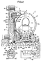
- Fig. 3
- is a view similar to Fig. 1, but according to a third embodiment of the present invention.
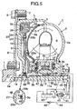
- Fig. 4
- is a view similar to Fig. 1, but according to a fourth embodiment of the present invention.
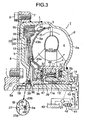
- Fig. 5
- is a view similar to Fig. 1, but according to a fifth embodiment of the present invention.
- Referring first to Fig. 1, a torque converter T as a fluid transmitting device includes a
pump impeller 2, aturbine runner 3 opposed to thepump impeller 2, and astator 4 disposed between inner peripheries of thepump impeller 2 and theturbine runner 3. Acirculation circuit 6 for transmitting a power by a working oil is defined among the threemembers - A
side cover 5 is integrally connected to an outer periphery of ashell 2a of thepump impeller 2 by welding, to cover an outer side face of theturbine runner 3. A plurality of connecting bosses 7 are arranged circumferentially around and welded to an outer peripheral surface of theside cover 5. Adrive plate 8 coupled to acrankshaft 1 of an engine is secured to the connecting bosses 7 by abolt 9. A thrust needle bearing 36 is interposed between ahub 3b of theturbine runner 3 and theside cover 5. - An
output shaft 10 is disposed at the center of the torque converter T to be coaxial with thecrankshaft 1. Theoutput shaft 10 is spline-fitted to thehub 3b of theturbine runner 3 and rotatably carried on asupport tube 5a provided at the center of theside cover 5 with a bearing bushing 18 interposed therebetween. Theoutput shaft 10 is a main shaft of a multi-stage transmission (not shown). - A
cylindrical stator shaft 12 is disposed around an outer periphery of theoutput shaft 10, and carries ahub 4b of thestator 4 through afree wheel 11. A needle bearing 13 is interposed between theoutput shaft 10 and thestator shaft 12 to permit the relative rotations of them. Thestator shaft 12 is non-rotatably supported at its outer end on atransmission case 14. -
Thrust needle bearings 37 and 37' are interposed between axially opposite end faces of thehub 4b of thestator 4 and end faces ofhubs pump impeller 2 and theturbine runner 3 which are opposed to the axially opposite end faces. The axial movements of theturbine runner 3 and thestator 4 between thepump impeller 2 and theside cover 5 are restricted by thethrust needle bearings 37 and 37' and the thrust needle bearing 36. - An auxiliary-driving
shaft 20 coupled to thepump impeller 2 is disposed relatively rotatably around an outer periphery of thestator shaft 12, and drives anoil pump 21 to supply the working oil to the torque converter T. - A
clutch chamber 22 is defined between theturbine runner 3 and theside cover 5 to communicate with thecirculation circuit 6 on the side of an outer periphery. A lock-up clutch L is mounted in theclutch chamber 22 and capable of coupling theturbine runner 3 and theside cover 5 directly to each other. More specifically, aclutch piston 19 constituting a main member of the lock-up clutch L is disposed in theclutch chamber 22 in such a manner that it divides theclutch chamber 22 into aninner oil chamber 23 on the side of theturbine runner 3 and anouter oil chamber 24 on the side of theside cover 5. Theclutch piston 19 is slidably carried on an outer peripheral surface of thehub 3b of theturbine runner 3 and has afriction lining 28 opposed to anannular friction surface 5b formed on an inner surface of theside cover 5. In addition, theclutch piston 19 is connected axially movably through a known torque damper D to a transmittingplate 34 fixedly mounted on an outer surface of theturbine runner 3. -
Annular partition walls 25 and 25' are formed on opposed surfaces of theshell 3a of theturbine runner 3 and theclutch piston 19 so that they are slidably and rotatably fitted to each other . Aseal member 26 is mounted on one of opposed peripheral surfaces of thepartition walls 25 and 25', so that it is in slidably close contact with the other opposed peripheral surface. Thepartition walls 25 and 25' constitute a dividing means 27 for dividing theinner oil chamber 23 in theclutch chamber 22 into a radially inner primary inner oil chamber ;section 23a and a radially outher secondary inneroil chamber section 23b. The partition wall 25' on the side of theturbine runner 3 may be provided on thehub 3b of the turbine runner - A through-
bore 30 is provided in thehub 3b of theturbine runner 3 to permit the primary inneroil chamber section 23a to communicate with anannular oil passage 29 between thehub 3b of theturbine runner 3 and thehub 4b of thestator 4 on the side of the inner periphery of thethrust needle bearing 37 . A through-bore 31 is provided in theshell 3a of theturbine runner 3 to permit the primary inneroil chamber section 23a to communicate with the inside of theshell 3a. - A
first oil passage 40 is provided at the center of theoutput shaft 10 to communicate with theouter oil chamber 24 in theclutch chamber 22 through atransverse bore 39 and thethrust needle bearing 36. Asecond oil passage 41 is defined between the auxiliary-drivingshaft 20 and thestator shaft 12, and communicates with an inner periphery of thecirculation circuit 6 through an annular oil passage 29' between thehub 2b of thepump impeller 2 and thehub 4b of thestator 4 and through the thrust needle bearing 37'. - A
third oil passage 44 is defined between theoutput shaft 10 and thestator shaft 12, and communicates with the inner periphery of thecirculation circuit 6 and with the primary inneroil chamber section 23a through theannular oil passage 29 between thehub 3b of theturbine runner 3 and thehub 4b of thestator 4 as well as through the through-bores thrust needle bearing 37. In this case, to cut off the communication between theannular oil passages 29 and 29', aseal member 49 is interposed between aninner race 11a of thefree wheel 11 and thestator shaft 12. - The
first oil passage 40 and thesecond oil passage 41 are adapted to be alternately connected to a discharge side of theoil pump 21 and anoil reservoir 43 by a lock-upcontrol valve 42, and also connected to theoil reservoir 43 through arelief valve 48 for maintaining thecirculation circuit 6 and the primary inneroil chamber section 23a under a predetermined pressure. Therefore, a surplus pressure in thecirculation circuit 6 and the primary inneroil chamber section 23a is released to theoil reservoir 43 through therelief valve 48. - The operation of this embodiment will be described below.
- In a driven state of the torque converter T, the lock-up
control valve 42 is controlled by an electronic control unit (not shown), to connect thefirst oil passage 40 to the discharge side of theoil pump 21, and on the other hand connects thesecond oil passage 41 to theoil reservoir 43. Therefore, when an output torque from thecrankshaft 1 of the engine is sequentially transmitted to thedrive plate 8, theside cover 5 and thepump impeller 2 to drive thepump impeller 2 to rotate, and further drive theoil pump 21, the working oil discharged by theoil pump 21 flows as shown by an arrow a from the lock-upcontrol valve 42 sequentially via thefirst oil passage 40, thetransverse bore 39 and thethrust needle bearing 36, theouter oil chamber 24 in theclutch chamber 22 and the second inneroil chamber section 23b of theinner oil chamber 23, into thecirculation circuit 6 to fill thecircuit 6. Thereafter, the working oil flows via the thrust needle bearing 37' and the annular oil passage 29' into thesecond oil passage 41, and then flows through the lock-upcontrol valve 42 back to theoil reservoir 43. - In the
clutch chamber 22, the pressure in theouter oil chamber 24 is higher than that in theinner oil chamber 23 due to the working oil flowing in the above-described manner, and theclutch piston 19 is retracted away from thefriction surface 5b of theside cover 5 by a difference between such pressures. Therefore, the lock-up clutch L is in a disconnected state, whereby the relative rotations of thepump impeller 2 and theturbine runner 3 are permitted. Thus, when thepump impeller 2 is driven to rotate by thecrankshaft 1, the working oil filling thecirculation circuit 6 circulates in thecirculation circuit 6 as shown by arrows, whereby the rotational torque of thepump impeller 2 is transmitted to theturbine runner 3 to drive theoutput shaft 10. - In this process, if a torque amplifying effect is generated between the
pump impeller 2 and theturbine runner 3, a reaction force resulting from such an effect is borne by thestator 4, and thestator 4 is fixed by the locking action of thefree wheel 11. - When the lock-up
control valve 42 is switched over by the electronic control unit to bring the lock-up clutch L into a connected state during the driving operation of the torque converter T, or during a decelerating operation of the torque converter T in which theturbine runner 3 is in a position to drive thepump impeller 2 to cause the working oil to flow in a direction opposite from the direction indicated by the arrows in thecirculation circuit 6, the working oil discharged from theoil pump 21 flows in a direction opposite from the above-described direction, as shown by an arrow b, that is, from the lock-upcontrol valve 42 sequentially via thesecond oil passage 41, the annular oil passage 29' and the thrust needle bearing 37' into thecirculation circuit 6. Then, the working oil passes through the through-bores oil chamber section 23a, and on the other hand passes through the outer periphery of thecirculation circuit 6 into the secondary inneroil chamber section 23b. - The
outer oil chamber 24 in theclutch chamber 22 is opened into theoil reservoir 43 through thefirst oil passage 40 and the lock-upcontrol valve 42. - The working oil introduced into the secondary inner
oil chamber section 23b is more or less leaked into the lower-pressureouter oil chamber 24 through a gap between theclutch piston 19 and theside cover 5, whereby the raising of the pressure in the secondary inneroil chamber section 23b is retarded. On the other hand, as soon as the working oil is introduced into the secondary inneroil chamber section 23b, the pressure in the secondary inneroil chamber section 23b is raised immediately to become higher than that in theouter oil chamber 24, because the first inneroil chamber section 23a is partitioned from the secondary inneroil chamber section 23b by thepartition walls 25 and 25', and moreover is maintained in a substantially sealed state by therelief valve 48. Therefore,clutch piston 19 is advanced toward thefriction surface 5b of theside cover 5 in sensitive response to the difference between the pressures, whereby the friction lining 28 is brought into pressure contact with thefriction surface 5b. Thus, the leakage of the working oil from the secondary inneroil chamber section 23b of theinner oil chamber 23 into theouter oil chamber 24 is inhibited by such pressure contact, and hence the pressure in the secondary inneroil chamber section 23b is also raised by the working oil subsequently introduced thereinto from thecirculation circuit 6, whereby theclutch piston 19 is urged further powerfully toward theside cover 5. In this manner, the lockup clutch L is brought into a powerful connected state. - Thus, if the lock-up
control valve 42 is switched over to connect the lock-up clutch L during either of the driving operation and the decelerating operating of the torque converter T, the pressure in the primary inneroil chamber section 23a is first raised relative to theouter oil chamber 25 to enhance the connection responsiveness of theclutch piston 19. Thus, the pressure in the secondary inneroil chamber section 23b can be also raised without a large retardation by inhibiting the leakage of the working oil from the secondary inneroil chamber section 23b of the inner oil chamber into the outer oil chamber, 24, so that the raising of the pressures in the primary and secondary inneroil chamber sections clutch piston 19 is sequentially generated in the primary inneroil chamber section 23a and the secondary inneroil chamber section 23b, whereby the shock of the connection of the lock-up clutch L can be alleviated. - To further enhance the connection responsiveness of the
clutch piston 19 particularly during the decelerating operation, it is effective that a through-bore is provided in theshell 3a of theturbine runner 3 to permit the communication between thecirculation circuit 6 and the secondary inneroil chamber section 23b. Namely, during the decelerating operation, the flow of the working oil in thecirculation circuit 6 is opposite from the direction indicated by the arrow in Fig. 1, and the pressure in an area of thecirculation circuit 6 on the side of theshell 3a is relatively high, and the working oil in such area flows through the through-bore into the secondary inneroil chamber section 23b to raise the pressure in thechamber section 23b, leading to the enhancement in connection responsiveness of theclutch piston 19. During a slowly accelerating operation, the flow of the working oil in thecirculation circuit 6 is in the direction indicated by the arrow in Fig. 1, and the pressure in an area of thecirculation circuit 6 in the vicinity of the through-bore is relatively low. This results in that the oil pressure in the secondary inneroil chamber section 23b escapes from the through-bore toward thecirculation circuit 6, and the retardation of the operation of theclutch piston 19 is brought about in contrast with the case during the decelerating operation. Therefore, when the through-bore as described above is provided, it is necessary to select the position and the size of the through-bore in consideration of the balance between the enhancement in connection responsiveness of theclutch piston 19 during the decelerating operation and the a reduction in connection responsiveness of theclutch piston 19 during the slowly accelerating operation. - When the lock-up
control valve 42 is switched over to disconnect the lock-up clutch L again, the working oil flows from theouter oil chamber 24 toward theinner oil chamber 23 to retract theclutch piston 19 away from thefriction surface 5b of theside cover 5 by the difference between the pressures in the outer andinner oil chambers circulation circuit 6 to thesecond oil chamber 41. Therefore, the flow of the working oil from theouter oil chamber 24 toward theinner oil chamber 23 can be ensured without provision of a one-way valve as in the prior art device, and the cooling of the lock-up clutch L can be promoted. Therefore, the number of parts can be , reduced, because the one-way valve is eliminated, so that it is possible to provide the torque converter T with the lock-up clutch at a low cost. - In the disconnected state of the lock-up clutch L, the torque damper D is not operated, and hence the
partition walls 25 and 25' are not rotated relative to each other by the rotation of theturbine runner 3 and theclutch piston 19 in unison with each other. In the connected state of the lock-up clutch L, thepartition walls 25 and 25' are rotated relative to each other only in a range of angle of operation of the torque damper D and hence, the friction of theseal member 26 is extremely small, whereby the durability of theseal member 26 can be easily ensured. - In the first embodiment, when the leakage of the working oil from the primary inner
oil chamber section 23a to the secondary inneroil chamber section 23b is permitted more or less, theseal member 26 can be eliminated from thepartition walls 25 and 25' constituting the dividing means 28. - A second embodiment of the present invention shown in Fig.2 will now be described.
- The second embodiment is of an arrangement similar to that in the first embodiment, except that a labyrinth packing 45 is arranged between the
partition walls 25 and 25' slidably and rotatably fitted to each other. Therefore, portions or components corresponding to those in the first embodiment are denoted by the same reference numerals in Fig. 2, and the descriptions thereof are omitted. - In the second embodiment, during a lock-up control carried out by the lock-up control valve, while eliminating the friction resistance between the
partition walls 25 and 25' , the leakage of the working oil from the primary inneroil chamber section 23a to the secondary inneroil chamber section 23b can be prevented, to further enhance the operation responsiveness of theclutch piston 19. - A third embodiment of the present invention shown in Fig. 3 will now be described.
- In the third embodiment, an
annular partition wall 25 is formed on one of opposed surfaces of theturbine runner 3 and theclutch piston 19. Aseal member 46 is mounted on an end face of thepartition wall 25 to protrude annularly therefrom. Theseal member 46 is constructed so that when theclutch piston 19 is retracted to a non-connected position spaced apart from thefriction surface 5b of theside cover 5, theseal member 46 is brought into close contact with the other of the opposed surfaces of theturbine runner 3 and theclutch piston 19 to divide theinner oil chamber 23 into a radially inner primary inneroil chamber section 23a and a radially outer secondary inneroil chamber section 23b. - The
second oil passage 41 communicates not only with the annular oil passage 29' but also with theannular oil passage 29 through anoil groove 33 defined in theinner race 11a of thefree wheel 11. Aseal member 47 is interposed between thehub 3b of theturbine runner 3 and thehub 4b of thestator 4 in order to effectively introduce the working oil supplied from thesecond oil passage 41 to theannular oil passage 29, into the primary inneroil chamber section 23a through the through-bore 30. A bushing 13' is disposed between theoutput shaft 10 and thestator shaft 12, in place of theneedle bearing 13 in the first embodiment. - In the other respects, the third embodiment is of an arrangement similar to that in the first embodiment, except that the
third oil passage 44 in the first embodiment is not provided. Therefore, portions or components corresponding to those in the first embodiment are denoted by the same reference numerals in Fig.3, and the descriptions thereof are omitted. - When the working oil is supplied to the primary inner
oil chamber section 23a during the lock-up control conducted by the lock-upcontrol valve 42, the pressure in the primary inneroil chamber section 23a is raised immediately to urge theclutch piston 19 toward theside cover 5, thereby bringing the friction lining 28 into pressure contact with the inner surface of theside cover 5. When theseal member 46 on thepartition wall 25 is moved away from the opposed surface of theturbine runner 3 or theclutch piston 19 with movement of theclutch piston 19, the working oil flows from the primary inneroil chamber section 23a through a gap provided between theseal member 46 and the opposed surface into the secondary inneroil chamber section 23b. The working oil is prevented from leaking to theouter oil chamber 24 by the pressure contact of thefriction surface 5b and the friction lining 28 with each other, so that the pressure in the secondary inneroil chamber section 23b is immediately raised. Therefore, even in this case, the lock-up clutch L is reliably brought into the connected state with a good responsiveness. Moreover, theseal member 46 is put in a non-contact state with the opposed surface of theturbine runner 3 or theclutch piston 19 in the operative state of the lock-up clutch L and hence, the friction of theseal member 46 is extremely small, whereby the durability thereof can be enhanced. - In the third embodiment, the
seal member 46 maybe removed, and thepartition wall 25 may be in metal contact with the opposed surface of theturbine runner 3 or theclutch piston 19. - Next, a fourth embodiment of the present invention shown in Fig.4 will be described below.
- The fourth embodiment is of an arrangement similar to that in the first embodiment, except that a single or a plurality of through-
bores 51 are provided in theshell 3a of theturbine runner 3 to permit the primaryinner chamber section 23a to communicate with thecirculation circuit 6. Therefore, portions or components corresponding to those in the first embodiment are denoted by the same reference numerals, and the descriptions thereof are omitted. - With the fourth embodiment, during the decelerating operation of the torque converter T in which the
turbine runner 3 is in a position to drive thepump impeller 2, the pressure in an area of thecirculation circuit 6 on the side of theturbine runner 3 is relatively high, whereby the working oil flows from thecirculation circuit 6 through the through-bore or bores 51 in theshell 3a of theturbine runner 3 into the primaryinner chamber section 23a, to raise the pressure in the primaryinner chamber section 23a. Therefore, during the lock-up control by the lock-upcontrol valve 42, the raising of the pressure in the primary and secondaryinner chamber sections - On the other hand, during the accelerating operation in which the lock-up clutch L is disconnected, and the
pump impeller 2 is rotated at a speed higher than theturbine runner 3, the working oil flows in thecirculation circuit 6 in a direction indicated by an arrow and as a result, the pressure in an area of thecirculation circuit 6 on the side of theturbine runner 3 is lower than that in an area on the side of thepump impeller 2. Therefore, the working oil in the primaryinner chamber section 23a flows therefrom through the through-bore or bores 51 into thecirculation circuit 6, to lower the pressure in the primaryinner chamber section 23a. However, the decrease of the pressure in the primaryinner chamber section 23a does not involve the secondaryinner chamber section 23b, because the through-bore or bores 51 do not communicate with the secondaryinner chamber section 23b, and moreover the primary and secondaryinner chamber sections inner chamber section 23b is maintained at a relatively high pressure, because it communicates with the outer periphery of thecirculation circuit 6. Therefore, when the lock-upcontrol valve 42 is switched over to bring the lock-up clutch L from this state into the connected state, theclutch piston 19 is operated to move toward theside cover 5 by a difference in pressure between the high-pressure secondaryinner chamber section 23b and the low-pressureouter chamber 24, whereby the lock-up clutch L can be brought into the connected state without hindrance. - Lastly, a fifth embodiment of the present invention shown in Fig.5 will now be described.
- In the fifth embodiment, the
second oil passage 41 communicates with theannular oil passage 29 through theneedle bearing 13 disposed between theoutput shaft 10 and thestator shaft 12, and further with the primary inneroil chamber section 23a through the through-bore 30. In this structure, a seal member 52 is disposed in the spline-fitting portion between theinner race 11a of thefree wheel 11 and thestator shaft 12, in order to prevent oil leak from theannular oil passage 29 to the spline-fitting portion. - The other structural components are the same as those in the third embodiment. Therefore, the components corresponding to those in the third embodiment are denoted by the same reference numerals and characters in Fig.5, and the descriptions thereof are omitted.
- According to the fifth embodiment, during the lock-up control by the lock-up
control valve 42, the working oil discharged from theoil pump 21 flows through thesecond oil passage 41 in the direction indicated by an arrow b, passes theneedle bearing 13, theannular oil passage 29 and the through-bore 30, to be supplied to the primary inneroil chamber section 23a. Since thecirculation circuit 6 is not present in the above-described route, the working oil which has been pressure-regulated by the lock-upcontrol valve 42 is efficiently supplied to the primary inneroil chamber section 23a without further changing its pressure or being influenced by the operational state of the torque converter T, whereby fine control of connection of the lock-up clutch can be achieved. - In the case where the
needle bearing 13 is replaced by the bushing, if a through-bore 53 is provided in thestator shaft 12 between the bushing and the seal member 52 so as to cause the working oil flowing through thesecond oil passage 41 in the direction indicated by the arrow b to pass the through-bore 53, the spline-fitting portion between theinner race 11a of thefree wheel 11 and thestator shaft 12, theannular oil passage 29 and the through-bore 30, to be supplied to the primary inneroil chamber section 23a during the lock-up control by the lock-upcontrol valve 42, the same effect as described above can be obtained.
Claims (5)
- A fluid transmitting device with a lock-up clutch, which includes a pump impeller (2), a turbine runner (3) defining a circulation circuit (6) between said turbine runner (3) itself and said pump impeller (2), a side cover (5) connected to said pump impeller (2) and defining a clutch chamber (22) between said side cover (5) itself and an outer surface of said turbine runner (3) to communicate with an outer periphery of said circulation circuit (6), and a lock-up clutch (L) disposed in said clutch chamber (22) and capable of connecting said side cover (5) and said turbine runner (3) directly to each other,
said lock-up clutch (L) comprising a clutch piston (19) axially movably connected to said turbine runner (3) to divide said clutch chamber (22) into an inner oil chamber (23) on the side of said turbine runner (3) and an outer oil chamber (24) on the side of said side cover (5), a lock-up control means (42) adapted to generate a difference in pressure between said inner oil chamber (23) and said outer oil chamber (24) in order to advance and retract said clutch piston (19) toward and away from an inner surface of said side cover (5), and a friction engaging means (5b, 28) adapted to bring said clutch piston (19) and said side cover (5) into friction engagement with each other, when said clutch piston (19) is urged toward the inner surface of said side cover (5),
wherein said fluid transmitting device further includes a dividing means (27) provided between said turbine runner (3) and said clutch piston (19),
characterized in that
said dividing means (27) divide said inner oil chamber (23) into a radially inner and substantially closed primary inner oil chamber section (23a) and a radially outer secondary inner oil chamber section (23b), when said clutch piston (19) occupies a retracted position in which at least the friction engaging means (5b, 28) is inoperative, so that when said lock-up control means (42) is operated to urge said clutch piston (19) in a direction of engagement of said friction engaging means (5b, 28), the pressures in said primary inner oil chamber section (23a) and said secondary inner oil chamber section (23b) are raised in the named order relative to said outer oil chamber (24), and
wherein said dividing means (27) comprises annular partition walls (25, 25') which are formed on opposed surfaces of a shell (3a) of said turbine runner (3) and said clutch piston (19), respectively, and which are slidably and rotatably fitted to each other. - A fluid transmitting device with a lock-up clutch (L) according to claim 1, further including a seal member (26) which is mounted on one of opposed peripheral surfaces of said annular partition walls (25, 25') formed on the opposed surfaces of the shell of said turbine runner (3) and said clutch piston (19) respectively and which are slidably and rotatably fitted to each other, the seal member (26) being in slidably close contact with the other opposed peripheral surface.
- A fluid transmitting device with a lock-up clutch (L) according to claim 1 or 2, further including a labyrinth packing (45) arranged between said partition walls (25, 25').
- A fluid transmitting device with a lock-up clutch, which includes a pump impeller (2), a turbine runner (3) defining a circulation circuit (6) between said turbine runner (3) itself and said pump impeller (2), a side cover (5) connected to said pump impeller (2) and defining a clutch chamber (22) between said side cover (5) itself and an outer surface of said turbine, runner (3) to communicate with an outer periphery of said circulation circuit (6), and a lock-up clutch (L) disposed in said clutch chamber (22) and capable of connecting said side cover (5) and said turbine runner (3) directly to each other,
said lock-up clutch (L) comprising a clutch piston (19) axially movably connected to said turbine runner (3) to divide said clutch chamber (22) into an inner oil chamber (23) on the side of said turbine runner (3) and an outer oil chamber (24) on the side of said side cover (5), a lock-up control means (42) adapted to generate a difference in pressure between said inner oil chamber (23) and said outer oil chamber (24) in order to advance and retract said clutch piston (19) toward and away from an inner surface of said side cover (5), and a friction engaging means (5b, 28) adapted to bring said clutch piston (19) and said side cover (5) into friction engagement with each other, when said clutch piston (19) is urged toward the inner surface of said side cover (5),
wherein said fluid transmitting device further includes a dividing means (27) provided between said turbine runner (3) and said clutch piston (19),
characterized in that
said dividing means (27) divide said inner oil chamber (23) into a radially inner and substantially closed primary inner oil chamber section (23a) and a radially outer secondary inner oil chamber section (23b), when said clutch piston (19) occupies a retracted position in which at least the friction engaging means (5b, 28) is inoperative, so that when said lock-up control means (42) is operated to urge said clutch piston (19) in a direction of engagement of said friction engaging means (5b, 28), the pressures in said primary inner oil chamber section (23a) and said secondary inner oil chamber section (23b) are raised in the named order relative to said outer oil chamber (24), and
wherein said dividing means (27) comprises an annular partition wall (25) formed on one of opposed surfaces of said turbine runner (3) and said clutch piston (19), and a seal member (46) mounted on said partition wall (25) to protrude annularly from an end face of said partition wall (25), said seal member (46) being brought into close contact with the other of the opposed surfaces of said turbine runner (3) and said clutch piston (19), when said clutch piston (19) is retracted to a non-connected position spaced apart from said side cover (5). - A fluid transmitting device with a lock-up clutch according to any one of claims 1 to 4, wherein said turbine runner (3) has a through-bore (51) to permit said primary inner oil chamber section (23a) to communicate with said circulation circuit (6).
Applications Claiming Priority (4)
| Application Number | Priority Date | Filing Date | Title |
|---|---|---|---|
| JP2001251945 | 2001-08-22 | ||
| JP2001251945 | 2001-08-22 | ||
| JP2002150435A JP2003139240A (en) | 2001-08-22 | 2002-05-24 | Hydraulic transmission with lock-up clutch |
| JP2002150435 | 2002-05-24 |
Publications (3)
| Publication Number | Publication Date |
|---|---|
| EP1288529A2 EP1288529A2 (en) | 2003-03-05 |
| EP1288529A3 EP1288529A3 (en) | 2004-12-08 |
| EP1288529B1 true EP1288529B1 (en) | 2006-04-05 |
Family
ID=26620816
Family Applications (1)
| Application Number | Title | Priority Date | Filing Date |
|---|---|---|---|
| EP02018710A Expired - Fee Related EP1288529B1 (en) | 2001-08-22 | 2002-08-21 | Fluid transmitting device with lock-up clutch |
Country Status (7)
| Country | Link |
|---|---|
| US (1) | US6729452B2 (en) |
| EP (1) | EP1288529B1 (en) |
| JP (1) | JP2003139240A (en) |
| CN (1) | CN1195949C (en) |
| CA (1) | CA2399200C (en) |
| DE (1) | DE60210383T2 (en) |
| TW (1) | TW552364B (en) |
Families Citing this family (10)
| Publication number | Priority date | Publication date | Assignee | Title |
|---|---|---|---|---|
| JP2005282617A (en) * | 2004-03-26 | 2005-10-13 | Aisin Seiki Co Ltd | Torque converter with lock-up clutch |
| JP4944624B2 (en) * | 2007-01-22 | 2012-06-06 | 本田技研工業株式会社 | Fluid transmission device |
| DE102007018273A1 (en) * | 2007-04-18 | 2008-10-23 | Zf Friedrichshafen Ag | Hydrodynamic coupling arrangement |
| JP5262833B2 (en) * | 2009-02-27 | 2013-08-14 | 日産自動車株式会社 | Vehicle clutch control device |
| CN101988569B (en) * | 2010-11-16 | 2013-02-27 | 浙江吉利汽车研究院有限公司 | Automobile dual-mass hydraulic torque converter |
| US9027724B2 (en) * | 2011-03-31 | 2015-05-12 | Aisin Aw Co., Ltd. | Starting device |
| CN102661377B (en) * | 2012-04-28 | 2015-04-22 | 长城汽车股份有限公司 | Hydraulic torque converter |
| US9322463B2 (en) * | 2014-04-25 | 2016-04-26 | Valeo Embrayages | Hydrokinetic torque coupling device with centered lock-up clutch friction disc, and method for assembling the same |
| US20180257184A1 (en) * | 2015-01-23 | 2018-09-13 | Schaeffler Technologies AG & Co. KG | Impeller shell with thickened junction and method thereof |
| US11105349B2 (en) * | 2019-07-09 | 2021-08-31 | Valeo Kapec Co., Ltd. | Hydrokinetic torque-coupling device having lock up clutch with dual piston assembly |
Family Cites Families (8)
| Publication number | Priority date | Publication date | Assignee | Title |
|---|---|---|---|---|
| JPH05296313A (en) | 1992-04-14 | 1993-11-09 | Nissan Motor Co Ltd | Lock-up mechanism for torque converter |
| US5667042A (en) * | 1994-04-26 | 1997-09-16 | Luk Lamellen Und Kupplungsbau Gmbh | Torque transmitting apparatus with hydrokinetic torque converter |
| JPH1137176A (en) * | 1997-07-24 | 1999-02-09 | Exedy Corp | Clutch operating piston structure |
| DE19905625A1 (en) * | 1998-02-17 | 1999-08-19 | Luk Getriebe Systeme Gmbh | Hydraulic power transmission system using polymer coated housing rear |
| DE19812687A1 (en) * | 1998-03-23 | 1999-09-30 | Mannesmann Sachs Ag | Automotive torque converter has friction pad ensuring |
| DE19842310A1 (en) * | 1998-09-16 | 2000-03-23 | Mannesmann Sachs Ag | Hydrodynamic coupling consists of circuit composed of pump and turbine wheel, and main circuit with bridging coupling |
| DE19953172A1 (en) * | 1999-11-04 | 2001-05-10 | Mannesmann Sachs Ag | Hydrodynamic coupling unit comprises a plain bearing arrangement incorporating a plain bearing element which is attached to the turbine wheel and fixes the latter in axial and radial directions relative to the housing |
| DE10221264B4 (en) * | 2001-05-15 | 2015-05-21 | Schaeffler Technologies AG & Co. KG | Hydrodynamic torque converter |
-
2002
- 2002-05-24 JP JP2002150435A patent/JP2003139240A/en active Pending
- 2002-08-21 EP EP02018710A patent/EP1288529B1/en not_active Expired - Fee Related
- 2002-08-21 TW TW091118920A patent/TW552364B/en not_active IP Right Cessation
- 2002-08-21 CA CA002399200A patent/CA2399200C/en not_active Expired - Fee Related
- 2002-08-21 DE DE60210383T patent/DE60210383T2/en not_active Expired - Fee Related
- 2002-08-22 US US10/225,299 patent/US6729452B2/en not_active Expired - Fee Related
- 2002-08-22 CN CNB02130257XA patent/CN1195949C/en not_active Expired - Fee Related
Also Published As
| Publication number | Publication date |
|---|---|
| EP1288529A3 (en) | 2004-12-08 |
| CN1401922A (en) | 2003-03-12 |
| CN1195949C (en) | 2005-04-06 |
| CA2399200A1 (en) | 2003-02-22 |
| DE60210383T2 (en) | 2007-01-04 |
| EP1288529A2 (en) | 2003-03-05 |
| US20030066726A1 (en) | 2003-04-10 |
| DE60210383D1 (en) | 2006-05-18 |
| TW552364B (en) | 2003-09-11 |
| JP2003139240A (en) | 2003-05-14 |
| CA2399200C (en) | 2005-10-18 |
| US6729452B2 (en) | 2004-05-04 |
Similar Documents
| Publication | Publication Date | Title |
|---|---|---|
| US7066312B2 (en) | Fluid transmitting system with lock-up clutch | |
| JP3024997B2 (en) | Liquid-air torque transmission unit | |
| US4271725A (en) | Hydraulic motor unit | |
| EP1043512B1 (en) | Rotating clutch balance apparatus | |
| EP1288529B1 (en) | Fluid transmitting device with lock-up clutch | |
| US6035989A (en) | Clutch-actuated piston structure | |
| JPS61119879A (en) | Sealing device sealed with fluid | |
| EP0770797B1 (en) | Hydraulic power transmission | |
| EP0409088B1 (en) | Torque converter assembly with reverse acting bypass clutch | |
| US6343679B1 (en) | Hydrodynamic clutch device, in particular hydrodynamic torque converter | |
| GB2289315A (en) | Hydrodynamic torque converter | |
| US4974715A (en) | Oil passages of torque converter | |
| EP0985852B1 (en) | Torque converter and seal arrangement | |
| US7353924B2 (en) | Hydrodynamic torque converter | |
| US6487855B1 (en) | Torque converter | |
| EP1445505B1 (en) | Fluid coupling | |
| US7694789B2 (en) | Starting unit | |
| EP1172577B1 (en) | Fluid coupling with baffle plate | |
| JP4349044B2 (en) | Fluid coupling | |
| EP2980452B1 (en) | Power transmission device for vehicle | |
| EP1445504B1 (en) | Fluid coupling | |
| JP3025240B2 (en) | Hydrodynamic torque converter with throttle element | |
| US3710570A (en) | Oil film bearing for converter element | |
| US7094179B2 (en) | Hydraulic transmission apparatus with lockup clutch | |
| JP2004036634A (en) | Hydraulic power transmission with lock-up clutch |
Legal Events
| Date | Code | Title | Description |
|---|---|---|---|
| PUAI | Public reference made under article 153(3) epc to a published international application that has entered the european phase |
Free format text: ORIGINAL CODE: 0009012 |
|
| AK | Designated contracting states |
Designated state(s): AT BE BG CH CY CZ DE DK EE ES FI FR GB GR IE IT LI LU MC NL PT SE SK TR Kind code of ref document: A2 Designated state(s): AT BE BG CH CY CZ DE DK EE ES FI FR GB GR IE IT LI LU MC NL PT SE SK TR |
|
| AX | Request for extension of the european patent |
Extension state: AL LT LV MK RO SI |
|
| PUAL | Search report despatched |
Free format text: ORIGINAL CODE: 0009013 |
|
| AK | Designated contracting states |
Kind code of ref document: A3 Designated state(s): AT BE BG CH CY CZ DE DK EE ES FI FR GB GR IE IT LI LU MC NL PT SE SK TR |
|
| AX | Request for extension of the european patent |
Extension state: AL LT LV MK RO SI |
|
| 17P | Request for examination filed |
Effective date: 20041222 |
|
| 17Q | First examination report despatched |
Effective date: 20050126 |
|
| AKX | Designation fees paid |
Designated state(s): DE GB |
|
| GRAP | Despatch of communication of intention to grant a patent |
Free format text: ORIGINAL CODE: EPIDOSNIGR1 |
|
| RBV | Designated contracting states (corrected) |
Designated state(s): DE GB |
|
| GRAS | Grant fee paid |
Free format text: ORIGINAL CODE: EPIDOSNIGR3 |
|
| GRAA | (expected) grant |
Free format text: ORIGINAL CODE: 0009210 |
|
| AK | Designated contracting states |
Kind code of ref document: B1 Designated state(s): DE GB |
|
| REG | Reference to a national code |
Ref country code: GB Ref legal event code: FG4D |
|
| REF | Corresponds to: |
Ref document number: 60210383 Country of ref document: DE Date of ref document: 20060518 Kind code of ref document: P |
|
| PGFP | Annual fee paid to national office [announced via postgrant information from national office to epo] |
Ref country code: GB Payment date: 20060810 Year of fee payment: 5 |
|
| PLBE | No opposition filed within time limit |
Free format text: ORIGINAL CODE: 0009261 |
|
| STAA | Information on the status of an ep patent application or granted ep patent |
Free format text: STATUS: NO OPPOSITION FILED WITHIN TIME LIMIT |
|
| 26N | No opposition filed |
Effective date: 20070108 |
|
| PGFP | Annual fee paid to national office [announced via postgrant information from national office to epo] |
Ref country code: DE Payment date: 20071030 Year of fee payment: 6 |
|
| GBPC | Gb: european patent ceased through non-payment of renewal fee |
Effective date: 20070821 |
|
| PG25 | Lapsed in a contracting state [announced via postgrant information from national office to epo] |
Ref country code: GB Free format text: LAPSE BECAUSE OF NON-PAYMENT OF DUE FEES Effective date: 20070821 |
|
| PG25 | Lapsed in a contracting state [announced via postgrant information from national office to epo] |
Ref country code: DE Free format text: LAPSE BECAUSE OF NON-PAYMENT OF DUE FEES Effective date: 20090303 |