EP1288514A2 - Insulating rotor coupling - Google Patents
Insulating rotor coupling Download PDFInfo
- Publication number
- EP1288514A2 EP1288514A2 EP02019013A EP02019013A EP1288514A2 EP 1288514 A2 EP1288514 A2 EP 1288514A2 EP 02019013 A EP02019013 A EP 02019013A EP 02019013 A EP02019013 A EP 02019013A EP 1288514 A2 EP1288514 A2 EP 1288514A2
- Authority
- EP
- European Patent Office
- Prior art keywords
- rotor
- generator
- steam turbine
- insulated structure
- side flange
- Prior art date
- Legal status (The legal status is an assumption and is not a legal conclusion. Google has not performed a legal analysis and makes no representation as to the accuracy of the status listed.)
- Granted
Links
Images



Classifications
-
- F—MECHANICAL ENGINEERING; LIGHTING; HEATING; WEAPONS; BLASTING
- F16—ENGINEERING ELEMENTS AND UNITS; GENERAL MEASURES FOR PRODUCING AND MAINTAINING EFFECTIVE FUNCTIONING OF MACHINES OR INSTALLATIONS; THERMAL INSULATION IN GENERAL
- F16D—COUPLINGS FOR TRANSMITTING ROTATION; CLUTCHES; BRAKES
- F16D1/00—Couplings for rigidly connecting two coaxial shafts or other movable machine elements
- F16D1/02—Couplings for rigidly connecting two coaxial shafts or other movable machine elements for connecting two abutting shafts or the like
- F16D1/033—Couplings for rigidly connecting two coaxial shafts or other movable machine elements for connecting two abutting shafts or the like by clamping together two faces perpendicular to the axis of rotation, e.g. with bolted flanges
-
- C—CHEMISTRY; METALLURGY
- C23—COATING METALLIC MATERIAL; COATING MATERIAL WITH METALLIC MATERIAL; CHEMICAL SURFACE TREATMENT; DIFFUSION TREATMENT OF METALLIC MATERIAL; COATING BY VACUUM EVAPORATION, BY SPUTTERING, BY ION IMPLANTATION OR BY CHEMICAL VAPOUR DEPOSITION, IN GENERAL; INHIBITING CORROSION OF METALLIC MATERIAL OR INCRUSTATION IN GENERAL
- C23C—COATING METALLIC MATERIAL; COATING MATERIAL WITH METALLIC MATERIAL; SURFACE TREATMENT OF METALLIC MATERIAL BY DIFFUSION INTO THE SURFACE, BY CHEMICAL CONVERSION OR SUBSTITUTION; COATING BY VACUUM EVAPORATION, BY SPUTTERING, BY ION IMPLANTATION OR BY CHEMICAL VAPOUR DEPOSITION, IN GENERAL
- C23C4/00—Coating by spraying the coating material in the molten state, e.g. by flame, plasma or electric discharge
-
- F—MECHANICAL ENGINEERING; LIGHTING; HEATING; WEAPONS; BLASTING
- F01—MACHINES OR ENGINES IN GENERAL; ENGINE PLANTS IN GENERAL; STEAM ENGINES
- F01D—NON-POSITIVE DISPLACEMENT MACHINES OR ENGINES, e.g. STEAM TURBINES
- F01D15/00—Adaptations of machines or engines for special use; Combinations of engines with devices driven thereby
- F01D15/10—Adaptations for driving, or combinations with, electric generators
-
- F—MECHANICAL ENGINEERING; LIGHTING; HEATING; WEAPONS; BLASTING
- F01—MACHINES OR ENGINES IN GENERAL; ENGINE PLANTS IN GENERAL; STEAM ENGINES
- F01D—NON-POSITIVE DISPLACEMENT MACHINES OR ENGINES, e.g. STEAM TURBINES
- F01D25/00—Component parts, details, or accessories, not provided for in, or of interest apart from, other groups
- F01D25/007—Preventing corrosion
-
- F—MECHANICAL ENGINEERING; LIGHTING; HEATING; WEAPONS; BLASTING
- F01—MACHINES OR ENGINES IN GENERAL; ENGINE PLANTS IN GENERAL; STEAM ENGINES
- F01D—NON-POSITIVE DISPLACEMENT MACHINES OR ENGINES, e.g. STEAM TURBINES
- F01D5/00—Blades; Blade-carrying members; Heating, heat-insulating, cooling or antivibration means on the blades or the members
- F01D5/02—Blade-carrying members, e.g. rotors
- F01D5/026—Shaft to shaft connections
-
- F—MECHANICAL ENGINEERING; LIGHTING; HEATING; WEAPONS; BLASTING
- F01—MACHINES OR ENGINES IN GENERAL; ENGINE PLANTS IN GENERAL; STEAM ENGINES
- F01K—STEAM ENGINE PLANTS; STEAM ACCUMULATORS; ENGINE PLANTS NOT OTHERWISE PROVIDED FOR; ENGINES USING SPECIAL WORKING FLUIDS OR CYCLES
- F01K23/00—Plants characterised by more than one engine delivering power external to the plant, the engines being driven by different fluids
- F01K23/12—Plants characterised by more than one engine delivering power external to the plant, the engines being driven by different fluids the engines being mechanically coupled
- F01K23/16—Plants characterised by more than one engine delivering power external to the plant, the engines being driven by different fluids the engines being mechanically coupled all the engines being turbines
-
- F—MECHANICAL ENGINEERING; LIGHTING; HEATING; WEAPONS; BLASTING
- F02—COMBUSTION ENGINES; HOT-GAS OR COMBUSTION-PRODUCT ENGINE PLANTS
- F02C—GAS-TURBINE PLANTS; AIR INTAKES FOR JET-PROPULSION PLANTS; CONTROLLING FUEL SUPPLY IN AIR-BREATHING JET-PROPULSION PLANTS
- F02C7/00—Features, components parts, details or accessories, not provided for in, or of interest apart form groups F02C1/00 - F02C6/00; Air intakes for jet-propulsion plants
- F02C7/36—Power transmission arrangements between the different shafts of the gas turbine plant, or between the gas-turbine plant and the power user
-
- F—MECHANICAL ENGINEERING; LIGHTING; HEATING; WEAPONS; BLASTING
- F05—INDEXING SCHEMES RELATING TO ENGINES OR PUMPS IN VARIOUS SUBCLASSES OF CLASSES F01-F04
- F05D—INDEXING SCHEME FOR ASPECTS RELATING TO NON-POSITIVE-DISPLACEMENT MACHINES OR ENGINES, GAS-TURBINES OR JET-PROPULSION PLANTS
- F05D2220/00—Application
- F05D2220/70—Application in combination with
- F05D2220/72—Application in combination with a steam turbine
-
- F—MECHANICAL ENGINEERING; LIGHTING; HEATING; WEAPONS; BLASTING
- F05—INDEXING SCHEMES RELATING TO ENGINES OR PUMPS IN VARIOUS SUBCLASSES OF CLASSES F01-F04
- F05D—INDEXING SCHEME FOR ASPECTS RELATING TO NON-POSITIVE-DISPLACEMENT MACHINES OR ENGINES, GAS-TURBINES OR JET-PROPULSION PLANTS
- F05D2220/00—Application
- F05D2220/70—Application in combination with
- F05D2220/74—Application in combination with a gas turbine
-
- F—MECHANICAL ENGINEERING; LIGHTING; HEATING; WEAPONS; BLASTING
- F05—INDEXING SCHEMES RELATING TO ENGINES OR PUMPS IN VARIOUS SUBCLASSES OF CLASSES F01-F04
- F05D—INDEXING SCHEME FOR ASPECTS RELATING TO NON-POSITIVE-DISPLACEMENT MACHINES OR ENGINES, GAS-TURBINES OR JET-PROPULSION PLANTS
- F05D2220/00—Application
- F05D2220/70—Application in combination with
- F05D2220/76—Application in combination with an electrical generator
-
- F—MECHANICAL ENGINEERING; LIGHTING; HEATING; WEAPONS; BLASTING
- F05—INDEXING SCHEMES RELATING TO ENGINES OR PUMPS IN VARIOUS SUBCLASSES OF CLASSES F01-F04
- F05D—INDEXING SCHEME FOR ASPECTS RELATING TO NON-POSITIVE-DISPLACEMENT MACHINES OR ENGINES, GAS-TURBINES OR JET-PROPULSION PLANTS
- F05D2230/00—Manufacture
- F05D2230/90—Coating; Surface treatment
-
- F—MECHANICAL ENGINEERING; LIGHTING; HEATING; WEAPONS; BLASTING
- F16—ENGINEERING ELEMENTS AND UNITS; GENERAL MEASURES FOR PRODUCING AND MAINTAINING EFFECTIVE FUNCTIONING OF MACHINES OR INSTALLATIONS; THERMAL INSULATION IN GENERAL
- F16B—DEVICES FOR FASTENING OR SECURING CONSTRUCTIONAL ELEMENTS OR MACHINE PARTS TOGETHER, e.g. NAILS, BOLTS, CIRCLIPS, CLAMPS, CLIPS OR WEDGES; JOINTS OR JOINTING
- F16B2200/00—Constructional details of connections not covered for in other groups of this subclass
- F16B2200/50—Flanged connections
-
- F—MECHANICAL ENGINEERING; LIGHTING; HEATING; WEAPONS; BLASTING
- F16—ENGINEERING ELEMENTS AND UNITS; GENERAL MEASURES FOR PRODUCING AND MAINTAINING EFFECTIVE FUNCTIONING OF MACHINES OR INSTALLATIONS; THERMAL INSULATION IN GENERAL
- F16B—DEVICES FOR FASTENING OR SECURING CONSTRUCTIONAL ELEMENTS OR MACHINE PARTS TOGETHER, e.g. NAILS, BOLTS, CIRCLIPS, CLAMPS, CLIPS OR WEDGES; JOINTS OR JOINTING
- F16B2200/00—Constructional details of connections not covered for in other groups of this subclass
- F16B2200/50—Flanged connections
- F16B2200/506—Flanged connections bolted or riveted
-
- Y—GENERAL TAGGING OF NEW TECHNOLOGICAL DEVELOPMENTS; GENERAL TAGGING OF CROSS-SECTIONAL TECHNOLOGIES SPANNING OVER SEVERAL SECTIONS OF THE IPC; TECHNICAL SUBJECTS COVERED BY FORMER USPC CROSS-REFERENCE ART COLLECTIONS [XRACs] AND DIGESTS
- Y10—TECHNICAL SUBJECTS COVERED BY FORMER USPC
- Y10S—TECHNICAL SUBJECTS COVERED BY FORMER USPC CROSS-REFERENCE ART COLLECTIONS [XRACs] AND DIGESTS
- Y10S464/00—Rotary shafts, gudgeons, housings, and flexible couplings for rotary shafts
- Y10S464/90—Electrically insulative member
Definitions
- the present invention relates to a rotor coupling having insulated structure that is preferably employed in power generating equipment in which a generator is disposed in between a steam turbine and a gas turbine or a rotating machinery such as another steam turbine. More specifically, the present invention relates to a rotor coupling having insulated structure that is designed to stop galvanic corrosion of the rotor, bearing members and the like which occurs due to the generation of shaft voltage.
- FIG. 8 An example of conventional power generating equipment will be explained with reference to Fig. 8.
- 1 is a steam turbine
- 2 is a generator
- 3 is a gas turbine or a rotating machinery such as another steam turbine (the following explanation employs a gas turbine as an example of this rotating machinery, however the same explanation applies to the case where another steam turbine is employed in place of the gas turbine).
- a rotor 1a of the steam turbine 1 and a rotor 2a of the generator 2 are connected to the same shaft via a clutch 5.
- the rotor 2a of the generator 2 and a rotor 3a of the gas turbine 3 are also connected to the same shaft by a rotor coupling 6.
- each rotor 1a, 2a, 3a is supported by bearing members 7 in a manner so as to permit rotation.
- a preventative measure for this type of damage calls for releasing shaft current by providing a grounding electrode 9a in between the steam turbine 1 and generator 2.
- grounding electrodes 9a, 9b alone were not a sufficient countermeasure to the shaft voltage, so that a new approach has been greatly desired.
- the present invention was conceived in view of the above-described circumstances and has as its objective the provision a rotor coupling having insulated structure that can assuredly prevent galvanic corrosion of rotors, bearing members and the like caused by shaft voltage in a shaft system that requires insulation and a design in which a generator is disposed in between a steam turbine and a gas turbine or a rotating machinery such as another steam turbine.
- the present invention employs the following means to resolve the above-described problems.
- the rotor coupling having insulated structure is characterized in being employed in power generating equipment in which a generator is disposed in between a steam turbine and a gas turbine or a rotating machinery such as another steam turbine, a generator rotor and a rotating machinery rotor are connected, a first grounding electrode is provided to the steam turbine rotor, and a second grounding electrode is provided to the generator rotor, wherein both the rotors between the generator and the steam turbine are connected in an electrically insulated state.
- the rotor coupling having insulated structure according to the first aspect of the present invention, by contacting a ground via the first and second grounding electrodes, the potential of each rotor can be reduced. Furthermore, in this rotor coupling having insulated structure, it is possible to stop the flow of current from the generator rotor to the first grounding electrode. Thus, it is possible to offer a design that is an effective countermeasure to the shaft voltage, and therefore, it can prevent galvanic corrosion of bearing members, rotors and the like which is caused by the shaft voltage.
- the rotor coupling having insulated structure according to the second aspect of the present invention is characterized in that there is provided in the rotor coupling having insulated structure according to the first aspect: a generator-side flange provided on a side of the generator rotor; a steam turbine-side flange provided on a side of the steam turbine rotor; an inter-flange insulating member that is held in between the generator-side flange and the steam turbine-side flange; and a connecting bolt for tightening the area between the generator-side flange and the steam turbine-side flange with the inter-flange insulating member held therebetween; wherein insulating members composed of an aluminum flame coated surface or bakelite material are provided to the inter-flange insulating member and the connecting bolt for interrupting the galvanization between the generator-side flange and the steam turbine-side flange.
- the galvanization between the generator-side flange and the steam turbine-side flange can be interrupted by the insulating parts. As a result, current flowing from the generator rotor to the first grounding electrode can be prevented.
- the rotor coupling having insulated structure according to the third aspect of the present invention is characterized in that the aluminum flame coated surface is coated with a silicon resin in the rotor coupling having insulated structure according to the second aspect.
- very fine pores generated in the aluminum layer of the aluminum flame coated layer can be covered with the silicon resin, improving the electrical insulating effect of the aluminum flame coated layer.
- the rotor coupling having insulated structure according to the fourth aspect of the present invention is characterized in that the aluminum flame coated surface is provided via an undercoat consisting of nickel chrome in the rotor coupling having insulated structure according to the second or third aspect.
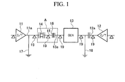
- FIG. 1 is an explanatory figure showing the rough design of a power generating equipment provided with the first embodiment of the rotor coupling having insulated structure of the present invention.
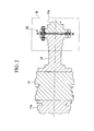
- FIG. 2 is a vertical cross-sectional view of part A in FIG. 1 showing an essential element of the power generating equipment.
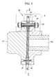
- FIG. 3 is an enlarged cross-sectional view of part B in FIG. 2 showing the rotor coupling having insulated structure provided to the essential element in the power generating equipment.
- FIG. 4 is a view of the rotor coupling having insulated structure as seen along arrow C-C in FIG. 3.
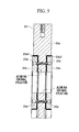
- FIG. 5 is an enlarged cross-sectional view of part D in FIG. 3 showing the rotor coupling having insulated structure.
- FIG. 6 is an enlarged cross-sectional view of part E in FIG. 3 showing the rotor coupling having insulated structure.
- FIG. 7 is an enlarged cross-sectional view of part F in FIG. 6 showing the rotor coupling having insulated structure.
- the power generating equipment of the present invention has a rough design in which a generator 13 is disposed in between a steam turbine 11 and a gas turbine 12 (rotating machinery), the area between a rotor 13a of the generator 13 and a rotor 11a of the steam turbine 11 are connected via a clutch 14 and a jack shaft 15, and the rotor 13a of the generator 13 and a rotor 12a of the gas turbine 12 are connected.
- the power generating equipment of this embodiment employs a design in which both the rotors 13a and 11a of the generator 13 and steam turbine 11 are connected via a rotor coupling having insulated structure 16 which links these rotors 13a and 1 1a in an electrically insulated manner, a first grounding electrode 17 (an earth electrode having a brush in which a tip end thereof slides against the outer surface of the rotor 11 a on the steam turbine 11 side) is provided to the rotor 11 a closer to the steam turbine 11 side than the rotor coupling having insulated structure 16, and a second grounding electrode 18 (an earth electrode having a brush in which a tip end thereof slides against the outer surface of the rotor 13a on the generator 13 side) is provided to the gas turbine 12 side of the rotor 13a of the generator 13.
- a first grounding electrode 17 an earth electrode having a brush in which a tip end thereof slides against the outer surface of the rotor 11 a on the steam turbine 11 side
- a second grounding electrode 18 an earth
- numeric symbols 19 in FIG. 1 indicate bearing members for supporting the each of the shafts of the rotor 1 1a, jack shaft 15, rotor 13a, and rotor 12a, etc.
- the rotor coupling having insulated structure 16 is provided with a generator-side flange 22 (provided in an unitary manner to the end of the rotor 13a) which is provided to the rotor 13a side of the generator 13; a steam turbine-side flange 21 (formed in a unitary manner to one end of the jack shaft 15) provided to the jack shaft 15 which is the rotor on the rotor 11a side of the steam turbine 11; an inter-flange insulating member 23 which is held in between the generator-side flange 22 and steam turbine-side flange 21; and a connecting bolt 24 which tightens the area between the generator-side flange 22 and steam turbine-side flange 21 with the inter-flange insulating member 23 held therebetween.
- Insulating parts consisting of bakelite or an aluminum flame coated surface are provided respectively to the inter-flange insulating member 23 and each connecting bolt 24 to interrupt galvanization between the generator-side flange 22 and steam turbine-side flange 21. These insulating parts consisting of an aluminum flame coated surface and bakelite will be explained in greater detail below.
- the inter-flange insulating member 23 is provided with a spacer 23a, a pair of rings 23b, 23c that form a convex socket and spigot portion which holds the spacer 23a from either side thereof; and a plurality of screws 23d that hold these rings 23b, 23c fixed in place with respect to the spacer 23a.
- the spacer 23a is a metallic circular disk for adjusting the dimensions of the space interval between the jack shaft 15 and rotor 13a.
- Circularly shaped concavities 23a1, 23a2 are formed to either side surface of the spacer 23a as convex socket and spigot portions for the engagement of each ring 23b, 23c along the same shaft respectively.
- Each ring 23b, 23c is a thin ring-shaped metallic piece, in which aluminum flame coating (the aluminum flame coating forming the insulating portion) has been formed to one side surface and the outer peripheral surface (the portion indicated by the thick line in FIG. 5) which comes into contact with the circular concavities 23a1, 23a2. Therefore, even when the ring 23b, 23c which are metallic parts are attached to the spacer 23a, it is possible to ensure an electrically insulated state between the rings 23b, 23c and spacer 23a.
- Each screw 23d for fixing these rings 23b, 23c in place is a part formed of bakelite (i.e., is an insulating part), so that an electrically insulated state can be maintained between the rings 23b, 23c and spacer 23a.
- the rings 23b, 23c which form these convex socket and spigot portions are designed to enable adjustment of the jack shaft 15 and rotor 13a along the same shaft by engaging in the concavities 21a, 22a formed in the flanges 21, 22 respectively.
- an undercoat consisting of nickel chrome is first applied to the flame coating surface, after which flame coating is carried out. Furthermore, since very fine pores are generated in the aluminum layer so that the insulating effect would be insufficient, a coating of silicon resin is applied over the entire surface in order to achieve a complete insulating effect. Note that while omitted from the following discussion, this same undercoating and silicon resin have been applied to each of the aluminum flame coated parts in the following explanation.
- the bolt main body 24a and nuts 24b are metallic parts, and rotation of the nuts 24b are prevented by the cotter pins 24c.
- the insulating sleeve 24d is a thin cylindrical part (insulating part) in which a bakelite material is wrapped around the outer periphery of the bolt main body 24a into which a spiral groove has been provided.
- the peripheral surface of the bolt main body 24a comes into contact with the bolt hole of the flanges 21, 22, making it possible to prevent electrical conduction of the jack shaft 15 and rotor 13a.
- Insulating rings 24f are ring-shaped parts (insulating parts) formed of bakelite, and are designed to engage in concavities 24el which are formed in each insulating washer 24e. These insulating rings 24f prevent electrical conduction between the jack shaft 15 and rotor 13a when the insulating washers 24e and flanges 21, 22 come into contact with one another.
- the power generating equipment of the present invention employs a design in which the rotor coupling having insulated structure 16 is provided in between the both rotors 13a ,11a of the generator 13 and steam turbine 11, the first grounding electrode 17 is provided to the rotor 11a closer to the steam turbine 11 side than the rotor coupling having insulated structure 16, and the second grounding electrode 18 is provided to the gas turbine 12 side of therotor 13a.
- the shaft voltage at the rotors 11a, 13a, 12a can be reduced by means of the first grounding electrode 17 and second grounding electrode 18, while the flow of current from the rotor 13a of the generator 13 to the first grounding electrode 17 can be interrupted.
- the present invention provides a strategy for assuredly preventing galvanic corrosion of the bearing members 19, rotors 11a, 12 and clutch 14.
- the rotor coupling having insulated structure 16 of this embodiment is provided with the generator-side flange 22, steam turbine-side flange 21, inter-flange insulating member 23, and connecting bolts 24; and insulating parts consisting of bakelite or aluminum flame coating are provided to the inter-flange insulating member 23 and connecting bolts 24.
- the rotor coupling having insulated structure 16 of this embodiment employs a design in which the aluminum flame coated surface is coated with a silicon resin. As a result of this design, there is greater assurance of the electrical insulating effect of the aluminum flame coated surface.
- the rotor coupling having insulated structure 16 of this embodiment employs a design in which the aluminum flame coated surface is provided via an undercoating consisting of nickel chrome. As a result of this design, the adherence of the aluminum flame coating to the target surface is improved, so that peeling of the aluminum flame coated surface is less likely.
Landscapes
- Engineering & Computer Science (AREA)
- Mechanical Engineering (AREA)
- General Engineering & Computer Science (AREA)
- Chemical & Material Sciences (AREA)
- Combustion & Propulsion (AREA)
- Materials Engineering (AREA)
- Plasma & Fusion (AREA)
- Chemical Kinetics & Catalysis (AREA)
- Physics & Mathematics (AREA)
- Metallurgy (AREA)
- Organic Chemistry (AREA)
- Motor Or Generator Frames (AREA)
- Iron Core Of Rotating Electric Machines (AREA)
- Turbine Rotor Nozzle Sealing (AREA)
- Coating By Spraying Or Casting (AREA)
- Connection Of Motors, Electrical Generators, Mechanical Devices, And The Like (AREA)
- Engine Equipment That Uses Special Cycles (AREA)
- Insulation, Fastening Of Motor, Generator Windings (AREA)
Abstract
Description
Claims (5)
- A rotor coupling having insulated structure being employed in a power generating equipment in which a generator is disposed in between a steam turbine and a gas turbine or a rotating machinery such as another steam turbine so as to connect a generator rotor and a rotating machinery rotor, and a first grounding electrode is provided to said gas turbine rotor and a second grounding electrode is provided to said generator rotor,
wherein both said rotors between said generator and said steam turbine are connected in an electrically insulated state. - A rotor coupling having insulated structure according to claim 1, comprising a generator-side flange provided on a side of said generator rotor, a steam turbine-side flange provided on a side of said steam turbine rotor, an inter-flange insulating member that is held in between said generator-side flange and said steam turbine-side flange, and a connecting bolt for tightening the area between said generator-side flange and said steam turbine-side flange with said inter-flange insulating member held therebetween; wherein insulating parts consisting of an aluminum flame coated surface or bakelite material are provided to said inter-flange insulating member and said connecting bolt for interrupting galvanization between said generator-side flange and said steam turbine-side flange.
- A rotor coupling having insulated structure according to claim 2, wherein said aluminum flame coated surface is coated with a silicon resin.
- A rotor coupling having insulated structure according to claim 2, wherein said aluminum flame coated surface is provided via an undercoat consisting of nickel chrome.
- A rotor coupling having insulated structure according to claim 3, wherein said aluminum flame coated surface is provided via an undercoat consisting of nickel chrome.
Applications Claiming Priority (2)
| Application Number | Priority Date | Filing Date | Title |
|---|---|---|---|
| JP2001256713 | 2001-08-27 | ||
| JP2001256713A JP4658407B2 (en) | 2001-08-27 | 2001-08-27 | Insulation type rotor coupling |
Publications (3)
| Publication Number | Publication Date |
|---|---|
| EP1288514A2 true EP1288514A2 (en) | 2003-03-05 |
| EP1288514A3 EP1288514A3 (en) | 2004-05-12 |
| EP1288514B1 EP1288514B1 (en) | 2007-07-18 |
Family
ID=19084493
Family Applications (1)
| Application Number | Title | Priority Date | Filing Date |
|---|---|---|---|
| EP02019013A Expired - Lifetime EP1288514B1 (en) | 2001-08-27 | 2002-08-26 | Insulating rotor coupling |
Country Status (6)
| Country | Link |
|---|---|
| US (1) | US7530757B2 (en) |
| EP (1) | EP1288514B1 (en) |
| JP (1) | JP4658407B2 (en) |
| CN (1) | CN1252382C (en) |
| CA (1) | CA2399551C (en) |
| DE (1) | DE60221203T2 (en) |
Cited By (3)
| Publication number | Priority date | Publication date | Assignee | Title |
|---|---|---|---|---|
| EP2933513A1 (en) * | 2014-04-15 | 2015-10-21 | Siemens Aktiengesellschaft | Coupling device for connecting a coupling to a turbine line |
| EP3848557A1 (en) * | 2020-01-10 | 2021-07-14 | Toshiba Energy Systems & Solutions Corporation | Gas turbine power generation system |
| WO2023006904A1 (en) * | 2021-07-30 | 2023-02-02 | Atlas Copco Airpower Nv | Shaft assembly |
Families Citing this family (20)
| Publication number | Priority date | Publication date | Assignee | Title |
|---|---|---|---|---|
| DE10321026A1 (en) * | 2003-05-10 | 2004-11-25 | Atlas Copco Energas Gmbh | turbomachinery |
| US7755876B2 (en) * | 2005-07-01 | 2010-07-13 | The Boeing Company | Fastening assembly including washer for sealing the assembly for lightning strike protection in composite structures |
| JP5072278B2 (en) * | 2006-07-18 | 2012-11-14 | 三菱重工業株式会社 | Hydraulic removable coupling |
| CN102209856B (en) * | 2008-11-14 | 2014-02-19 | 东芝三菱电机产业系统株式会社 | power transmission device |
| US9140135B2 (en) * | 2010-09-28 | 2015-09-22 | United Technologies Corporation | Metallic radius block for composite flange |
| US8434964B2 (en) * | 2010-06-18 | 2013-05-07 | General Electric Company | Electrical isolator for couplings |
| JP2012077702A (en) * | 2010-10-04 | 2012-04-19 | Toshiba Corp | Steam turbine rotor, method of manufacturing the same, and steam turbine |
| DE202011106443U1 (en) * | 2011-09-28 | 2011-11-22 | Khd Humboldt Wedag Gmbh | flange |
| DE102013210076A1 (en) * | 2013-05-29 | 2014-12-04 | Siemens Aktiengesellschaft | clutch |
| US9216495B2 (en) * | 2013-07-09 | 2015-12-22 | General Electric Company | Spacer |
| US20160047307A1 (en) * | 2014-08-15 | 2016-02-18 | General Electric Company | Power train architectures with low-loss lubricant bearings and low-density materials |
| JP6168362B2 (en) * | 2014-09-05 | 2017-07-26 | 株式会社オートネットワーク技術研究所 | Circuit structure, electrical junction box and spacer |
| JP6563235B2 (en) * | 2015-04-01 | 2019-08-21 | 株式会社東芝 | Insulating spacer of rotor of rotating electrical machine |
| US20190003514A1 (en) * | 2017-06-30 | 2019-01-03 | Spartan Motors, Inc. | Dual laminate galvanic isolation |
| DE102017212060B4 (en) * | 2017-07-14 | 2024-07-18 | Bayerische Motoren Werke Aktiengesellschaft | Coupling device |
| CN109653873A (en) * | 2018-11-13 | 2019-04-19 | 中国航发贵阳发动机设计研究所 | A kind of aero-engine onboard generators multifunctional ports design method |
| CN109245421A (en) * | 2018-11-15 | 2019-01-18 | 山东齐鲁电机制造有限公司 | A kind of rotor structure for Double shaft-extension generator amature one point earth |
| JP7502587B2 (en) * | 2019-03-12 | 2024-06-19 | ダイキン工業株式会社 | Compressor |
| DE102021202834A1 (en) * | 2021-03-23 | 2022-09-29 | Pilgrim International Ltd. | Clamping screw and associated arrangement |
| CN114123663A (en) * | 2021-12-09 | 2022-03-01 | 江苏中工高端装备研究院有限公司 | Current isolating device and method for permanent magnet synchronous semi-direct-drive variable frequency speed regulation motor shaft |
Family Cites Families (19)
| Publication number | Priority date | Publication date | Assignee | Title |
|---|---|---|---|---|
| US2158182A (en) * | 1934-08-31 | 1939-05-16 | Robert H Goddard | Heat insulating coupling |
| US2289620A (en) * | 1941-03-12 | 1942-07-14 | Victor Mfg & Gasket Co | Metal sprayed gasket |
| US2449654A (en) * | 1942-12-23 | 1948-09-21 | Jessop Robert Edison Edouard | Shaft coupling |
| US2435731A (en) * | 1943-10-21 | 1948-02-10 | Air Prod Inc | Expansion valve |
| US3138226A (en) * | 1961-02-14 | 1964-06-23 | Atkinson Guy F Co | Self-aligning device |
| US3862771A (en) * | 1973-04-18 | 1975-01-28 | Walter Schwarz | Electrically insulating tube coupling |
| ES438990A1 (en) * | 1974-09-30 | 1977-02-01 | Gen Electric | Shaft end coupling for a dynamoelectric machine |
| JPS5584321U (en) * | 1978-12-07 | 1980-06-10 | ||
| US4407602A (en) | 1982-01-29 | 1983-10-04 | General Electric Company | Insulated coupling |
| JPS6023627A (en) | 1983-07-19 | 1985-02-06 | Nippon Pillar Packing Co Ltd | Shaft joint |
| JPS61130616A (en) | 1984-11-29 | 1986-06-18 | Nippon Pillar Packing Co Ltd | Electric insulation shaft joint |
| JPS61238592A (en) * | 1985-04-15 | 1986-10-23 | Yoshikawa Kogyo Kk | Coupling structure of stern shaft mechanism |
| JPS61190402U (en) * | 1985-05-20 | 1986-11-27 | ||
| JPH0544571Y2 (en) * | 1985-09-25 | 1993-11-12 | ||
| JPH0746538B2 (en) * | 1985-11-19 | 1995-05-17 | 三菱重工業株式会社 | Insulated flange joint for torque transmission of ship propulsion |
| US4755904A (en) * | 1986-06-06 | 1988-07-05 | The Boeing Company | Lightning protection system for conductive composite material structure |
| JPH05141205A (en) * | 1991-11-18 | 1993-06-08 | Fuji Electric Co Ltd | Electrolytic corrosion prevention structure for main oil pump bearings in turbine power generation equipment |
| DE19524218B4 (en) * | 1994-08-19 | 2006-01-26 | Alstom | KombiAnlage |
| JP4865119B2 (en) | 1999-12-24 | 2012-02-01 | 日新製鋼株式会社 | Insulating substrate for solar cell having excellent heat resistance and method for producing the same |
-
2001
- 2001-08-27 JP JP2001256713A patent/JP4658407B2/en not_active Expired - Lifetime
-
2002
- 2002-08-22 CN CNB021301697A patent/CN1252382C/en not_active Expired - Lifetime
- 2002-08-23 CA CA002399551A patent/CA2399551C/en not_active Expired - Fee Related
- 2002-08-26 DE DE60221203T patent/DE60221203T2/en not_active Expired - Lifetime
- 2002-08-26 US US10/227,312 patent/US7530757B2/en not_active Expired - Lifetime
- 2002-08-26 EP EP02019013A patent/EP1288514B1/en not_active Expired - Lifetime
Cited By (6)
| Publication number | Priority date | Publication date | Assignee | Title |
|---|---|---|---|---|
| EP2933513A1 (en) * | 2014-04-15 | 2015-10-21 | Siemens Aktiengesellschaft | Coupling device for connecting a coupling to a turbine line |
| WO2015158511A1 (en) * | 2014-04-15 | 2015-10-22 | Siemens Aktiengesellschaft | Coupling device for connecting a clutch to a turbine train |
| US10316894B2 (en) | 2014-04-15 | 2019-06-11 | Siemens Aktiengesellschaft | Coupling device for connecting a clutch to a turbine train |
| EP3848557A1 (en) * | 2020-01-10 | 2021-07-14 | Toshiba Energy Systems & Solutions Corporation | Gas turbine power generation system |
| US11441488B2 (en) | 2020-01-10 | 2022-09-13 | Toshiba Energy Systems & Solutions Corporation | Gas turbine power generation system |
| WO2023006904A1 (en) * | 2021-07-30 | 2023-02-02 | Atlas Copco Airpower Nv | Shaft assembly |
Also Published As
| Publication number | Publication date |
|---|---|
| CA2399551A1 (en) | 2003-02-27 |
| DE60221203T2 (en) | 2008-04-03 |
| CN1252382C (en) | 2006-04-19 |
| CN1401887A (en) | 2003-03-12 |
| JP2003065006A (en) | 2003-03-05 |
| CA2399551C (en) | 2007-02-27 |
| DE60221203D1 (en) | 2007-08-30 |
| EP1288514B1 (en) | 2007-07-18 |
| US7530757B2 (en) | 2009-05-12 |
| EP1288514A3 (en) | 2004-05-12 |
| US20030052557A1 (en) | 2003-03-20 |
| JP4658407B2 (en) | 2011-03-23 |
Similar Documents
| Publication | Publication Date | Title |
|---|---|---|
| CA2399551C (en) | Rotor coupling having insulated structure | |
| EP3744972B1 (en) | Rotor for a wind turbine and wind turbine | |
| WO2020158396A1 (en) | Rotating electric machine and dump truck equipped therewith | |
| US20030038559A1 (en) | Spoke construction for an Ac generator's two-piece exciter diode wheel | |
| CN110953128B (en) | Wind turbine | |
| KR102726993B1 (en) | Motor shaft ground ring | |
| CN220754491U (en) | Motor shaft end sealing structure and motor | |
| US20130027835A1 (en) | Joint | |
| CN114785024B (en) | Insulation connector and wind turbine | |
| US4889494A (en) | Device for transmission of electrical currents and rotating machine parts | |
| EP3935280B1 (en) | Electrical connection device for a wind turbine, wind turbine and method for producing an electrical connection device | |
| JP6563235B2 (en) | Insulating spacer of rotor of rotating electrical machine | |
| JPH0313978Y2 (en) | ||
| JPS6013217Y2 (en) | electrical equipment container | |
| CN114785019A (en) | Insulation connection structure and wind turbine comprising the same | |
| CN217935269U (en) | Oil seal structure and motor device | |
| CN223402351U (en) | Conductive ring for preventing bearing from being electrically corroded | |
| CN211429144U (en) | Rotor current eliminating device of external rotor motor | |
| CN220307075U (en) | Novel bearingless unit motor shaft current inhibition structure of wind turbine generator system | |
| CN218235982U (en) | Flywheel of engine, engine and vehicle | |
| TW202121779A (en) | Electric slip ring device | |
| CN120955993A (en) | A grounding carbon brush device for a large-diameter motor | |
| CN211046635U (en) | Generator bearing protective structure | |
| Maharana et al. | Case Study of Failure of Neutral Flexible Link and Hexagonal Bus Header Plate and Palm Connector of 210MW Generator and Recommendations to Prevent Similar Faults | |
| Tanneau et al. | Custom power interface |
Legal Events
| Date | Code | Title | Description |
|---|---|---|---|
| PUAI | Public reference made under article 153(3) epc to a published international application that has entered the european phase |
Free format text: ORIGINAL CODE: 0009012 |
|
| 17P | Request for examination filed |
Effective date: 20020826 |
|
| AK | Designated contracting states |
Kind code of ref document: A2 Designated state(s): AT BE BG CH CY CZ DE DK EE ES FI FR GB GR IE IT LI LU MC NL PT SE SK TR |
|
| AX | Request for extension of the european patent |
Extension state: AL LT LV MK RO SI |
|
| PUAL | Search report despatched |
Free format text: ORIGINAL CODE: 0009013 |
|
| AK | Designated contracting states |
Kind code of ref document: A3 Designated state(s): AT BE BG CH CY CZ DE DK EE ES FI FR GB GR IE IT LI LU MC NL PT SE SK TR |
|
| AX | Request for extension of the european patent |
Extension state: AL LT LV MK RO SI |
|
| RIC1 | Information provided on ipc code assigned before grant |
Ipc: 7F 01D 25/00 B Ipc: 7F 01D 5/02 B Ipc: 7F 16D 1/00 A Ipc: 7F 01D 13/00 B |
|
| 17Q | First examination report despatched |
Effective date: 20041119 |
|
| AKX | Designation fees paid |
Designated state(s): CH DE FR GB IT LI |
|
| GRAP | Despatch of communication of intention to grant a patent |
Free format text: ORIGINAL CODE: EPIDOSNIGR1 |
|
| GRAS | Grant fee paid |
Free format text: ORIGINAL CODE: EPIDOSNIGR3 |
|
| GRAA | (expected) grant |
Free format text: ORIGINAL CODE: 0009210 |
|
| AK | Designated contracting states |
Kind code of ref document: B1 Designated state(s): CH DE FR GB IT LI |
|
| REG | Reference to a national code |
Ref country code: GB Ref legal event code: FG4D |
|
| REG | Reference to a national code |
Ref country code: CH Ref legal event code: EP |
|
| REF | Corresponds to: |
Ref document number: 60221203 Country of ref document: DE Date of ref document: 20070830 Kind code of ref document: P |
|
| REG | Reference to a national code |
Ref country code: CH Ref legal event code: NV Representative=s name: E. BLUM & CO. AG PATENT- UND MARKENANWAELTE VSP |
|
| ET | Fr: translation filed | ||
| PLBE | No opposition filed within time limit |
Free format text: ORIGINAL CODE: 0009261 |
|
| STAA | Information on the status of an ep patent application or granted ep patent |
Free format text: STATUS: NO OPPOSITION FILED WITHIN TIME LIMIT |
|
| 26N | No opposition filed |
Effective date: 20080421 |
|
| REG | Reference to a national code |
Ref country code: DE Ref legal event code: R082 Ref document number: 60221203 Country of ref document: DE Representative=s name: PATENTANWAELTE HENKEL, BREUER & PARTNER, DE Ref country code: DE Ref legal event code: R081 Ref document number: 60221203 Country of ref document: DE Owner name: MITSUBISHI HITACHI POWER SYSTEMS, LTD., YOKOHA, JP Free format text: FORMER OWNER: MITSUBISHI HEAVY INDUSTRIES, LTD., TOKYO, JP Ref country code: DE Ref legal event code: R082 Ref document number: 60221203 Country of ref document: DE Representative=s name: PATENTANWAELTE HENKEL, BREUER & PARTNER MBB, DE |
|
| REG | Reference to a national code |
Ref country code: FR Ref legal event code: PLFP Year of fee payment: 14 |
|
| PGFP | Annual fee paid to national office [announced via postgrant information from national office to epo] |
Ref country code: GB Payment date: 20150826 Year of fee payment: 14 Ref country code: CH Payment date: 20150811 Year of fee payment: 14 |
|
| PGFP | Annual fee paid to national office [announced via postgrant information from national office to epo] |
Ref country code: FR Payment date: 20150629 Year of fee payment: 14 |
|
| REG | Reference to a national code |
Ref country code: FR Ref legal event code: CA Effective date: 20151119 |
|
| REG | Reference to a national code |
Ref country code: GB Ref legal event code: 732E Free format text: REGISTERED BETWEEN 20151203 AND 20151209 |
|
| PGFP | Annual fee paid to national office [announced via postgrant information from national office to epo] |
Ref country code: IT Payment date: 20150827 Year of fee payment: 14 |
|
| REG | Reference to a national code |
Ref country code: FR Ref legal event code: TP Owner name: MITSUBISHI HITACHI POWER SYSTEMS, LTD., JP Effective date: 20151222 |
|
| REG | Reference to a national code |
Ref country code: CH Ref legal event code: PL |
|
| GBPC | Gb: european patent ceased through non-payment of renewal fee |
Effective date: 20160826 |
|
| PG25 | Lapsed in a contracting state [announced via postgrant information from national office to epo] |
Ref country code: CH Free format text: LAPSE BECAUSE OF NON-PAYMENT OF DUE FEES Effective date: 20160831 Ref country code: LI Free format text: LAPSE BECAUSE OF NON-PAYMENT OF DUE FEES Effective date: 20160831 |
|
| REG | Reference to a national code |
Ref country code: FR Ref legal event code: ST Effective date: 20170428 |
|
| PG25 | Lapsed in a contracting state [announced via postgrant information from national office to epo] |
Ref country code: FR Free format text: LAPSE BECAUSE OF NON-PAYMENT OF DUE FEES Effective date: 20160831 Ref country code: GB Free format text: LAPSE BECAUSE OF NON-PAYMENT OF DUE FEES Effective date: 20160826 |
|
| PG25 | Lapsed in a contracting state [announced via postgrant information from national office to epo] |
Ref country code: IT Free format text: LAPSE BECAUSE OF NON-PAYMENT OF DUE FEES Effective date: 20160826 |
|
| PGFP | Annual fee paid to national office [announced via postgrant information from national office to epo] |
Ref country code: DE Payment date: 20210713 Year of fee payment: 20 |
|
| REG | Reference to a national code |
Ref country code: DE Ref legal event code: R071 Ref document number: 60221203 Country of ref document: DE |