EP1288498A2 - Diaphragm pump for a fuel cell - Google Patents
Diaphragm pump for a fuel cell Download PDFInfo
- Publication number
- EP1288498A2 EP1288498A2 EP02014823A EP02014823A EP1288498A2 EP 1288498 A2 EP1288498 A2 EP 1288498A2 EP 02014823 A EP02014823 A EP 02014823A EP 02014823 A EP02014823 A EP 02014823A EP 1288498 A2 EP1288498 A2 EP 1288498A2
- Authority
- EP
- European Patent Office
- Prior art keywords
- fuel cell
- diaphragm pump
- piston
- anode
- anode gas
- Prior art date
- Legal status (The legal status is an assumption and is not a legal conclusion. Google has not performed a legal analysis and makes no representation as to the accuracy of the status listed.)
- Granted
Links
Images


Classifications
-
- H—ELECTRICITY
- H01—ELECTRIC ELEMENTS
- H01M—PROCESSES OR MEANS, e.g. BATTERIES, FOR THE DIRECT CONVERSION OF CHEMICAL ENERGY INTO ELECTRICAL ENERGY
- H01M8/00—Fuel cells; Manufacture thereof
- H01M8/04—Auxiliary arrangements, e.g. for control of pressure or for circulation of fluids
- H01M8/04082—Arrangements for control of reactant parameters, e.g. pressure or concentration
- H01M8/04089—Arrangements for control of reactant parameters, e.g. pressure or concentration of gaseous reactants
- H01M8/04097—Arrangements for control of reactant parameters, e.g. pressure or concentration of gaseous reactants with recycling of the reactants
-
- F—MECHANICAL ENGINEERING; LIGHTING; HEATING; WEAPONS; BLASTING
- F04—POSITIVE - DISPLACEMENT MACHINES FOR LIQUIDS; PUMPS FOR LIQUIDS OR ELASTIC FLUIDS
- F04B—POSITIVE-DISPLACEMENT MACHINES FOR LIQUIDS; PUMPS
- F04B43/00—Machines, pumps, or pumping installations having flexible working members
- F04B43/02—Machines, pumps, or pumping installations having flexible working members having plate-like flexible members, e.g. diaphragms
-
- Y—GENERAL TAGGING OF NEW TECHNOLOGICAL DEVELOPMENTS; GENERAL TAGGING OF CROSS-SECTIONAL TECHNOLOGIES SPANNING OVER SEVERAL SECTIONS OF THE IPC; TECHNICAL SUBJECTS COVERED BY FORMER USPC CROSS-REFERENCE ART COLLECTIONS [XRACs] AND DIGESTS
- Y02—TECHNOLOGIES OR APPLICATIONS FOR MITIGATION OR ADAPTATION AGAINST CLIMATE CHANGE
- Y02E—REDUCTION OF GREENHOUSE GAS [GHG] EMISSIONS, RELATED TO ENERGY GENERATION, TRANSMISSION OR DISTRIBUTION
- Y02E60/00—Enabling technologies; Technologies with a potential or indirect contribution to GHG emissions mitigation
- Y02E60/30—Hydrogen technology
- Y02E60/50—Fuel cells
Definitions
- This invention is related to a diaphragm pump and an anode stream recirculation system using such pump for a fuel cell, in particular, an anode stream recirculation system used in a proton exchange membrane fuel cell as well as the diaphragm pump used in such system, and most particularly, a hydrogen recirculation system and the diaphragm pump utilized in a proton exchange membrane fuel cell.
- the present invention eliminates certain elements required in the conventional anode stream recirculation system for a fuel cell and, thus reduces the cost for manufacture of the components of the fuel cell. Furthermore, this invention lowers the electrical energy required to operate the anode stream recirculation system so that the overall efficiency of electrical power generation for the fuel cell system can be promoted.
- the fuel cell is one of the most important and reasonably priced energy resources. Compared with traditional internal combustion engines, the fuel cell has many advantages such as high energy conversion efficiency, clean exhaust, low noise, and no consumption of traditional gasoline.
- a fuel cell is an electrical power generation device powered by the electrochemical reaction of hydrogen and oxygen.
- the reaction is a reverse reaction of the electrolysis of water, to convert the chemical energy into electrical energy.
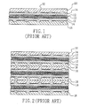
- the basic structure of a fuel cell for example, a proton exchange membrane fuel cell, comprises a plurality of cell units.
- the structure of the cell unit generally illustrated in Fig. 1 comprises a proton exchange membrane (PEM) 10 at the middle, with the two sides thereof provided with a layer of catalyst 12, each of the two outsides of the catalyst 12 is further provided with a gas diffusion layer (GDL) 14.
- GDL gas diffusion layer
- An anode plate 16 and a cathode plate 18 are further provided at the outermost sides adjacent to the GDL 14.
- a plurality of the above cell units are stacked and serially connected to provide sufficient power, as illustrated in Fig. 2. Therefore, two adjacent cell units can share a common polar plate 20, as illustrated in Fig. 3, which serves as the anode and the cathode for the two adjacent cell units, respectively. Accordingly, such a polar plate 20 is usually referred as a bipolar plate.
- a polar plate 20 is usually referred as a bipolar plate.
- the two sides of the bipolar plate 20 are provided with many groove type gas channels 22 for transporting the gases for reaction, such as hydrogen and air (to provide oxygen), as well as transporting the reactants, such as water droplets or vapor, out of the bipolar plate 20.
- One conventional gas supply system for use in a fuel cell comprises: a cathode gas supply system (such as an oxygen supply), and an anode circulation system (such as a hydrogen circulation system), as illustrated in Fig. 4.
- Atmospheric air may serve as a supply of the oxygen supply system 30, where air is filtered by a filter 32 and than pumped into the fuel cell 50 through a blower 34.
- Excessive air upon reaction within the fuel cell 50, is discharged through a water recuperator 36.
- the water recuperator 36 may recuperate the minute amount of water contained within the discharged air, where the water is then directed to a cooling system 38.
- the useless heat generated by the fuel cell 50 is also transmitted to the cooling system 38.
- the coolant used in the cooling system 38 then re-enters the fuel cell 50 to provide sufficient cooling thereto.
- the conventional anode circulation system includes: a hydrogen source 40 which regulates hydrogen input through a pressure regulator 42; a hydrogen pump 44 being provided at the other end of the fuel cell 50 for discharging excessive hydrogen, upon reaction within the fuel cell, and for pumping the hydrogen source 40 into the fuel cell 50.
- the excessive hydrogen is discharged through a humidifier 46, such as a bubbler, for increasing the humidity of the excessive hydrogen, then flows back into the piping of the hydrogen supply to be mixed with fresh hydrogen, and then repeats the same circulation.
- the water within the cooling system 38 can be transmitted to the water within the humidifier 46
- the hydrogen within the bipolar plate of the fuel cell must have adequate humidity such that the hydrogen ions (H + ) after reaction can be carried through the PEM by the water vapor.
- the hydrogen ions then react with the oxygen at the other side of the PEM and the electrons provided from the outer circuit, to establish proton conduction.
- the humidity of the hydrogen is too low, the PEM will be dehydrated, thus, the electrical resistance of the fuel cell will increase and the voltage of the fuel cell will decrease, which will result in the working life of the fuel cell being significantly shortened.
- the channels for transporting the gases within the bipolar plate may be clogged by water droplets, which will stop the reaction of gases within the fuel cell and the performance of the fuel cell will be seriously impaired. Accordingly, in the anode stream recirculation system, a humidifier to adjust the humidity of the hydrogen is generally required.
- a primary objective of this invention is to improve the conventional anode stream recirculation system by utilizing a diaphragm pump for continuously collecting the excessive hydrogen discharged from the fuel cell, and then directing the collected hydrogen back into the fuel cell for reaction. Therefore, the conventional hydrogen pump may be eliminated, the parasitic loss of electrical energy of the fuel cell itself can be reduced, and the overall efficiency of electrical power generation by the fuel cell system can be promoted.
- Another objective of this invention is that the anode stream recirculation system and the diaphragm pump can be further connected with a water circulation system.
- the water in the water circulation system can be driven by the diaphragm pump simultaneously. Therefore, the driving pump necessary for conventional water circulation system of the fuel cell may also be eliminated and thus, the parasitic loss of electrical energy of the fuel cell can be further reduced and the overall efficiency of electrical power generation by the fuel cell system is further promoted by this invention.
- a further objective of this invention is to automatically clear out the gas channels of the bipolar plates within the fuel cell by the pressure pulses introduced from intermittently switching on/off the hydrogen source so that no water droplet will stay within the gas channels to impair the power generation efficiency of the fuel cell.
- the primary technical contents of this invention are related to an anode stream recirculation system for a fuel cell, the fuel cell including an anode gas input and an anode gas output, the anode stream recirculation system comprising: an anode gas supply; a switch connected with the anode gas supply; a pressure regulating device connected between the switch and the anode gas input of the fuel cell; a diaphragm pump connected between the anode gas output and the anode gas input of the fuel cell thereby forming an anode gas recirculation; wherein the diaphragm pump has at least a sensor electrically connected with the switch.
- the diaphragm pump utilized in the anode stream recirculation system for the fuel cell.
- the diaphragm pump has a wall defining an interior space, a piston provided in the interior space, and a diaphragm assembly sealing with the piston and the wall of the diaphragm pump thereby dividing the interior space into two portions.
- This invention is related to an anode stream recirculation system for a fuel cell, in particular, a hydrogen recirculation system utilized in a proton exchange membrane (PEM) fuel cell.
- PEM proton exchange membrane
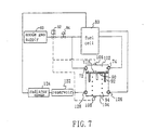
- One preferred embodiment of this invention is substantially shown in Fig. 5, which includes an anode gas supply 60 to provide the anode gas required for the reaction proceeded in the fuel cell 80.
- the anode gas is hydrogen.
- the anode gas flows through a switch 62 and a pressure regulating device 64 before entering the fuel cell 80 through an anode gas input 82.
- the switch 62 can be a solenoid valve which is used to control the open/close of the gas flow in the piping and to determine whether fresh anode gas should be released from the anode gas supply 60.
- the pressure regulating device 64 is used to adjust the pressure of the anode gas flowing therethrough. Generally, the flowing amount of the anode gas is set to be higher than the required Stoichiometric amount for a specific electrical power generation of the fuel cell so as to ensure that the electro-chemical reaction takes place completely within the fuel cell 80.
- the fuel cell 80 also has an anode gas output 84.
- the anode stream recirculation system further comprises a diaphragm pump 70 connected with both the anode gas output 84 and the anode gas input 82 of the fuel cell 80 thereby forming an anode gas recirculation as illustrated in Fig. 5.
- the anode stream recirculation system further comprises two check valves 72 and 74 with one provided between the anode gas input 82 of the fuel cell 80 and the diaphragm pump 70, and the other provided between the anode gas output 84 of the fuel cell 80 and the diaphragm pump 70.
- the check valves 72 and 74 are mounted on the two sides of the diaphragm pump 70.
- the diaphragm pump 70 has a wall 76 defining.an interior space and a piston 90 is provided in the interior space.
- a diaphragm 92 is attached over the piston 90 and is sealing with the wall 76 of the diaphragm pump 70.
- the diaphragm 92 can be made of rubber and divides the interior space into two portions 102 and 104.
- the wall 76 of the diaphragm pump 70 further comprises an opening 96 for atmosphere.
- the portion 102 of the interior space is adjoined with the anode stream recirculation system, and the other portion 104 of the interior space is communicated with atmosphere.
- the piston 90 lies on an elastic device, such as a spring 94.
- the diaphragm pump 70 has two Hall effect sensors 106 and 108 mounted on the top side and bottom side of the diaphragm pump 70, respectively.
- the Hall effect sensor may be model No. HAL504UA-E produced by Micronas Company, or model No. DN6848-ND produced by Panasonic Company, or any other types of sensors that can perform a similar function as described below.
- a magnetic member, such as a magnet 110, is mounted on the piston 90.
- the piston 90 can move up and down, depending on variation of the pressure of the portions 102 and 104 on the two sides of the diaphragm 92, as well as the elastic force provided by the spring 94.
- the two sensors 106 and 108 sense the position of the piston 90 by the magnet 110 thereon.
- the flowing rate and the pressure of the anode gas supply 60 are set to be higher than the required Stoichiometric amount for a specific electrical power generation of the fuel cell 80 so as to ensure that the electro-chemical reaction takes place completely within the fuel cell 80. Accordingly, excessive anode gas will be discharged into the output piping and be collected in the portion 102 of the diaphragm pump 70 through the anode gas output 84.
- the pressure of the portion 104 remains at a constant atmospheric pressure.
- the switch 62 When the switch 62 is switched on, the anode gas from the anode gas supply 60 with significantly higher pressure will thrust into the whole system, the pressure of the portion 102 thus increases and thereby moves the piston 90 downwardly and compresses the spring 94.
- the sensor 108 senses the position of the approaching magnet 110 on the piston 90 and transmits a signal to switch off the switch 62. At this time, no more fresh anode gas is supplied.
- the electro-chemical reaction within the fuel cell 80 proceeds, the anode gas will be consumed and the pressure in the system decreases. Therefore, the piston 90 is forced upwardly by the elastic force of the spring 94 and the atmospheric pressure to further expel the anode gas stored in the portion 102 into the fuel cell 80.
- the anode gas within the portion 102 will be consumed progressively, and the excessive anode gas discharged from the fuel cell 80 keeps decreasing. Accordingly, the pressure in the portion 102 keeps decreasing and the pump 90 keeps moving upwardly.
- the sensor 106 senses the approaching magnet 110 on the piston 90 and thus, transmits another signal to switch on the switch 62. As a result, fresh anode gas is again supplied from the anode gas supply 60 and thrusts into the whole system, and the piston 90 is therefore compressed downwardly.
- the anode recirculation system of this invention can recycle excessive anode gas that has not been reacted, and automatically redirect this gas back into the fuel cell for reaction.
- the hydrogen pump 44 required in the conventional technique for gas recirculation is utterly unnecessary.
- This invention therefore reduces the parasitic loss of electrical energy of the fuel cell itself. For this preferred embodiment, about 5% of the generated electrical power from the fuel cell can be saved and thus, the overall efficiency of electrical power generation by the fuel cell system is promoted.
- the diaphragm pump 70 may not be communicated with atmosphere, instead, it is communicated with a water circulation system.
- the water circulation system further comprises a reservoir 122 to contain the circulation water and a radiator 124 to lower the water temperature.
- the circulation water may also be directed to the fuel cell 80 to cool it.
- the water circulation system is connected with the diaphragm pump 70 through check valves 126 and 128 for input and output of the circulation water.
- the portion 104 of the diaphragm pump 70 is now filled with water instead of air.
- the driving pump necessary for conventional water circulation system of the fuel cell 80 may also be eliminated and thus, the parasitic loss of electrical energy of the fuel cell can be further reduced and the overall efficiency of electrical power generation by the fuel cell system is further promoted by this invention.
- the diaphragm pump according to this invention involves simple construction with low manufacture costs, and it does not need to consume any energy during operation.
- the anode gas with significantly higher pressure will thrust into the whole system, especially into the fuel cell 80.
- any water droplet condensed from the reaction of the fuel cell 80 or any undesired particle existing within the gas channels 22 of the bipolar plate 20 will be shattered and/or expelled out of the gas channels 22 by such intermittent high-pressure thrust gas.
- this invention also provides a function of intermittently and automatically clearing out the gas channels within the fuel cell.
Landscapes
- Engineering & Computer Science (AREA)
- Life Sciences & Earth Sciences (AREA)
- Sustainable Development (AREA)
- Chemical Kinetics & Catalysis (AREA)
- Sustainable Energy (AREA)
- Chemical & Material Sciences (AREA)
- Manufacturing & Machinery (AREA)
- Electrochemistry (AREA)
- General Chemical & Material Sciences (AREA)
- Mechanical Engineering (AREA)
- General Engineering & Computer Science (AREA)
- Fuel Cell (AREA)
- Reciprocating Pumps (AREA)
Abstract
Description
- 10
- proton exchange membrane
- 12
- catalyst
- 14
- gas diffusion layer
- 16
- anode plate
- 18
- cathode plate
- 20
- bipolar plate
- 22
- gas channels
- 30
- oxygen supply system
- 32
- filter
- 34
- blower
- 36
- water recuperator
- 38
- cooling system
- 40
- hydrogen source
- 42
- pressure regulator
- 44
- hydrogen pump
- 46
- humidifier
- 50
- fuel cell
- 60
- anode gas supply
- 62
- switch
- 64
- pressure regulating device
- 70
- diaphragm pump
- 72
- check valve
- 74
- check valve
- 76
- wall
- 80
- fuel cell
- 82
- anode gas input
- 84
- anode gas output
- 90
- piston
- 92
- diaphragm
- 94
- spring
- 96
- opening
- 102
- space
- 104
- space
- 106
- Hall effect sensor
- 108
- Hall effect sensor
- 110
- magnetic member
- 122
- reservoir
- 124
- radiator
- 126
- check valve
- 128
- check valve
Claims (15)
- An anode stream recirculation system for a fuel cell, the fuel cell including an anode gas input and an anode gas output, the anode stream recirculation system comprising:an anode gas supply;a switch connected with the anode gas supply;a pressure regulating device connected between the switch and the anode gas input of the fuel cell;a diaphragm pump connected between the anode gas output and the anode gas input of the fuel cell thereby forming an anode gas recirculation; wherein the diaphragm pump has at least a sensor electrically connected with the switch.
- The anode stream recirculation system for a fuel cell according to Claim 1, wherein the anode gas is hydrogen.
- The anode stream recirculation system for a fuel cell according to Claim 1, wherein the switch is an electromagnetic valve.
- The anode stream recirculation system for a fuel cell according to Claim 1, wherein the diaphragm pump has a wall defining an interior space, a piston provided in the interior space, and a diaphragm assembly sealing with the piston and the wall of the diaphragm pump thereby dividing the interior space into two portions.
- The anode stream recirculation system for a fuel cell according to Claim 4, wherein the diaphragm pump comprises two Hall effect sensors with one disposed at an upper side and the other disposed at a lower side of the diaphragm pump, and a magnetic member disposed on the piston to interact with the Hall effect sensors.
- The anode stream recirculation system for a fuel cell according to Claim 5, further comprising an elastic device resisting against a bottom of the piston to provide an upward force to the piston.
- The anode stream recirculation system for a fuel cell according to Claim 6, wherein the piston is adapted to move between a first position and a second position depending on variation of pressure on two sides of the diaphragm assembly and the force provided by the elastic device; the two sensors are used to sense the piston by detecting the magnetic member, when the piston moves to the first position, one of the sensor transmits a signal to switch off the switch, when the piston moves to the second position, the other sensor transmits another signal to switch on the switch.
- The anode stream recirculation system for a fuel cell according to Claim 4, wherein the diaphragm pump further comprises an opening such that a portion of the interior space of the diaphragm pump is communicated with atmosphere.
- The anode stream recirculation system for a fuel cell according to Claim 1, further comprising two check valves with one provided between the anode gas input of the fuel cell and the diaphragm pump, and the other provided between the anode gas output of the fuel cell and the diaphragm pump.
- The anode stream recirculation system for a fuel cell according to Claim 4, wherein the diaphragm pump further comprises a water inlet and a water outlet, thereby a portion of the interior space of the diaphragm pump is filled with water by communicating with a water circulation system.
- A diaphragm pump for a fuel cell, the diaphragm pump is used in an anode stream recirculation system for the fuel cell, the diaphragm pump comprising a wall defining an interior space, a piston provided in the interior space, and a diaphragm assembly sealing with the piston and the wall of the diaphragm pump thereby dividing the interior space into two portions.
- The diaphragm pump according to Claim 11, further comprising an elastic device resisting against a bottom of the piston to provide an upward force to the piston; the piston is adapted to move between a first position and a second position depending on variation of pressure on two sides of the diaphragm assembly and the force provided by the elastic device.
- The diaphragm pump according to Claim 11, further comprising at least one sensor to sense the piston.
- The diaphragm pump according to Claim 13, wherein the diaphragm pump comprises two Hall effect sensors with one disposed at an upper side and the other disposed at a lower side of the diaphragm pump, and a magnetic member disposed on the piston to interact with the Hall effect sensors.
- The diaphragm pump according to Claim 11, wherein the diaphragm assembly comprises a diaphragm made of rubber.
Applications Claiming Priority (2)
| Application Number | Priority Date | Filing Date | Title |
|---|---|---|---|
| CN01124277 | 2001-08-23 | ||
| CN01124277A CN1407644A (en) | 2001-08-23 | 2001-08-23 | Diaphragm pump for fuel cell and anode gas circulation system using the diaphragm pump |
Publications (3)
| Publication Number | Publication Date |
|---|---|
| EP1288498A2 true EP1288498A2 (en) | 2003-03-05 |
| EP1288498A3 EP1288498A3 (en) | 2003-04-02 |
| EP1288498B1 EP1288498B1 (en) | 2004-10-20 |
Family
ID=4665622
Family Applications (1)
| Application Number | Title | Priority Date | Filing Date |
|---|---|---|---|
| EP02014823A Expired - Lifetime EP1288498B1 (en) | 2001-08-23 | 2002-07-03 | Diaphragm pump for a fuel cell |
Country Status (4)
| Country | Link |
|---|---|
| EP (1) | EP1288498B1 (en) |
| CN (1) | CN1407644A (en) |
| AT (1) | ATE280440T1 (en) |
| DE (1) | DE60201648D1 (en) |
Cited By (1)
| Publication number | Priority date | Publication date | Assignee | Title |
|---|---|---|---|---|
| US20100190082A1 (en) * | 2009-01-28 | 2010-07-29 | Korea Institute Of Science And Technology | Fuel Cell |
Families Citing this family (6)
| Publication number | Priority date | Publication date | Assignee | Title |
|---|---|---|---|---|
| DE102006017964B4 (en) * | 2006-04-13 | 2008-12-24 | Sabik Informationssysteme Gmbh | Mixing unit for a fuel cell |
| US9356304B2 (en) * | 2008-01-11 | 2016-05-31 | GM Global Technology Operations LLC | Anode recirculation pump control strategy |
| TWI509871B (en) * | 2014-01-08 | 2015-11-21 | Nat Univ Tainan | Passive gas recovery system of fuel cell anode |
| CN109980243B (en) * | 2019-04-30 | 2023-11-10 | 肇庆学院 | A liquid fuel cell working system and control method |
| CN112687916B (en) * | 2020-12-28 | 2021-10-19 | 北京理工大学 | A hybrid energy storage system for fuel cell vehicles |
| CN112901444A (en) * | 2021-02-09 | 2021-06-04 | 山东建筑大学 | Linear reciprocating type hydrogen circulating pump |
Family Cites Families (5)
| Publication number | Priority date | Publication date | Assignee | Title |
|---|---|---|---|---|
| DE3430721A1 (en) * | 1984-08-21 | 1986-03-06 | Alldos Eichler Kg, 7507 Pfinztal | DIAPHRAGM PUMP, ESPECIALLY FOR DOSING LIQUIDS |
| DE8801660U1 (en) * | 1988-02-10 | 1988-03-31 | Henkel, Wolfgang Eberhard, 6832 Hockenheim | Diaphragm strain gauge for ball diaphragm pumps |
| DE4141670C2 (en) * | 1991-12-17 | 1994-09-29 | Ott Kg Lewa | Hydraulically driven diaphragm pump with diaphragm stroke limitation |
| EP0741428A1 (en) * | 1995-05-04 | 1996-11-06 | FINMECCANICA S.p.A. AZIENDA ANSALDO | A supply system for fuel cells of the S.P.E. (SOLID POLYMER ELECTROLYTE) type for hybrid vehicles). |
| US5798186A (en) * | 1996-06-07 | 1998-08-25 | Ballard Power Systems Inc. | Method and apparatus for commencing operation of a fuel cell electric power generation system below the freezing temperature of water |
-
2001
- 2001-08-23 CN CN01124277A patent/CN1407644A/en active Pending
-
2002
- 2002-07-03 DE DE60201648T patent/DE60201648D1/en not_active Expired - Lifetime
- 2002-07-03 AT AT02014823T patent/ATE280440T1/en not_active IP Right Cessation
- 2002-07-03 EP EP02014823A patent/EP1288498B1/en not_active Expired - Lifetime
Cited By (2)
| Publication number | Priority date | Publication date | Assignee | Title |
|---|---|---|---|---|
| US20100190082A1 (en) * | 2009-01-28 | 2010-07-29 | Korea Institute Of Science And Technology | Fuel Cell |
| US8709671B2 (en) * | 2009-01-28 | 2014-04-29 | Korea Institute Of Science And Technology | Fuel cell with air channel actuator |
Also Published As
| Publication number | Publication date |
|---|---|
| ATE280440T1 (en) | 2004-11-15 |
| EP1288498B1 (en) | 2004-10-20 |
| CN1407644A (en) | 2003-04-02 |
| EP1288498A3 (en) | 2003-04-02 |
| DE60201648D1 (en) | 2004-11-25 |
Similar Documents
| Publication | Publication Date | Title |
|---|---|---|
| US7008717B2 (en) | Diaphragm pump and anode stream recirculation system using such pump for a fuel cell | |
| EP1284514B1 (en) | Anode stream recirculation system for a fuel cell | |
| US5976722A (en) | Process for operating a fuel cell installation and fuel cell installation for carrying out the process | |
| CN101513830B (en) | Apparatus for optimized cooling of a drive unit and a fuel cell in a fuel cell vehicle | |
| US6692852B2 (en) | Generating system for a fuel cell, and heat waste recirculating and cooling system of said generating system | |
| EP1288498A2 (en) | Diaphragm pump for a fuel cell | |
| US20020150801A1 (en) | Anode stream recirculation system for a fuel cell | |
| EP1284515A2 (en) | Generating system for a fuel cell, and heat waste recirculating and cooling system of said generating system | |
| CN113471486A (en) | Integrated hydrogen circulating device for hydrogen fuel cell system | |
| HK1222707A1 (en) | Electrochemical refrigeration systems and appliances | |
| CN117334970B (en) | A liquid-cooled hydrogen fuel cell system for electric bicycles | |
| KR20210106126A (en) | Hydrogen charging system using hydrogen compressor | |
| CN118299625A (en) | Hydrogen energy power-backup system | |
| US9797635B2 (en) | Electrochemical refrigeration systems and appliances | |
| US20060194087A1 (en) | Cooling system and method for using fuel of fuel cell as refrigerant | |
| CN215680742U (en) | Solid oxide fuel cell stack | |
| US7971671B2 (en) | Drive unit, hydraulic working machine, and electric vehicle | |
| EP1284511A2 (en) | Bipolar plate for a fuel cell | |
| CN116031443A (en) | Test platform of hydrogen production and power generation integrated reversible system | |
| US20060141322A1 (en) | Fuel cell system | |
| CN115090080A (en) | Absorption regeneration decoupling type carbon capture system | |
| JP2005032685A (en) | Fuel cell system | |
| US20180183076A1 (en) | Fuel cell stack | |
| CN220233244U (en) | Tail gas energy recovery device, exhaust system and hydrogen fuel cell system | |
| JP4035313B2 (en) | Fuel cell with water electrolysis function |
Legal Events
| Date | Code | Title | Description |
|---|---|---|---|
| PUAI | Public reference made under article 153(3) epc to a published international application that has entered the european phase |
Free format text: ORIGINAL CODE: 0009012 |
|
| PUAL | Search report despatched |
Free format text: ORIGINAL CODE: 0009013 |
|
| AK | Designated contracting states |
Kind code of ref document: A2 Designated state(s): AT BE BG CH CY CZ DE DK EE ES FI FR GB GR IE IT LI LU MC NL PT SE SK TR |
|
| AX | Request for extension of the european patent |
Extension state: AL LT LV MK RO SI |
|
| AK | Designated contracting states |
Kind code of ref document: A3 Designated state(s): AT BE BG CH CY CZ DE DK EE ES FI FR GB GR IE IT LI LU MC NL PT SE SK TR |
|
| AX | Request for extension of the european patent |
Extension state: AL LT LV MK RO SI |
|
| RIC1 | Information provided on ipc code assigned before grant |
Ipc: 7F 04B 43/02 B Ipc: 7H 01M 8/04 A |
|
| 17P | Request for examination filed |
Effective date: 20030828 |
|
| 17Q | First examination report despatched |
Effective date: 20031107 |
|
| AKX | Designation fees paid |
Designated state(s): AT BE BG CH CY CZ DE DK EE ES FI FR GB GR IE IT LI LU MC NL PT SE SK TR |
|
| GRAP | Despatch of communication of intention to grant a patent |
Free format text: ORIGINAL CODE: EPIDOSNIGR1 |
|
| GRAS | Grant fee paid |
Free format text: ORIGINAL CODE: EPIDOSNIGR3 |
|
| GRAA | (expected) grant |
Free format text: ORIGINAL CODE: 0009210 |
|
| AK | Designated contracting states |
Kind code of ref document: B1 Designated state(s): AT BE BG CH CY CZ DE DK EE ES FI FR GB GR IE IT LI LU MC NL PT SE SK TR |
|
| PG25 | Lapsed in a contracting state [announced via postgrant information from national office to epo] |
Ref country code: SK Free format text: LAPSE BECAUSE OF FAILURE TO SUBMIT A TRANSLATION OF THE DESCRIPTION OR TO PAY THE FEE WITHIN THE PRESCRIBED TIME-LIMIT Effective date: 20041020 Ref country code: IT Free format text: LAPSE BECAUSE OF FAILURE TO SUBMIT A TRANSLATION OF THE DESCRIPTION OR TO PAY THE FEE WITHIN THE PRESCRIBED TIME-LIMIT;WARNING: LAPSES OF ITALIAN PATENTS WITH EFFECTIVE DATE BEFORE 2007 MAY HAVE OCCURRED AT ANY TIME BEFORE 2007. THE CORRECT EFFECTIVE DATE MAY BE DIFFERENT FROM THE ONE RECORDED. Effective date: 20041020 Ref country code: LI Free format text: LAPSE BECAUSE OF FAILURE TO SUBMIT A TRANSLATION OF THE DESCRIPTION OR TO PAY THE FEE WITHIN THE PRESCRIBED TIME-LIMIT Effective date: 20041020 Ref country code: CH Free format text: LAPSE BECAUSE OF FAILURE TO SUBMIT A TRANSLATION OF THE DESCRIPTION OR TO PAY THE FEE WITHIN THE PRESCRIBED TIME-LIMIT Effective date: 20041020 Ref country code: CZ Free format text: LAPSE BECAUSE OF FAILURE TO SUBMIT A TRANSLATION OF THE DESCRIPTION OR TO PAY THE FEE WITHIN THE PRESCRIBED TIME-LIMIT Effective date: 20041020 Ref country code: AT Free format text: LAPSE BECAUSE OF FAILURE TO SUBMIT A TRANSLATION OF THE DESCRIPTION OR TO PAY THE FEE WITHIN THE PRESCRIBED TIME-LIMIT Effective date: 20041020 Ref country code: EE Free format text: LAPSE BECAUSE OF FAILURE TO SUBMIT A TRANSLATION OF THE DESCRIPTION OR TO PAY THE FEE WITHIN THE PRESCRIBED TIME-LIMIT Effective date: 20041020 Ref country code: FI Free format text: LAPSE BECAUSE OF FAILURE TO SUBMIT A TRANSLATION OF THE DESCRIPTION OR TO PAY THE FEE WITHIN THE PRESCRIBED TIME-LIMIT Effective date: 20041020 Ref country code: BE Free format text: LAPSE BECAUSE OF FAILURE TO SUBMIT A TRANSLATION OF THE DESCRIPTION OR TO PAY THE FEE WITHIN THE PRESCRIBED TIME-LIMIT Effective date: 20041020 Ref country code: BG Free format text: LAPSE BECAUSE OF FAILURE TO SUBMIT A TRANSLATION OF THE DESCRIPTION OR TO PAY THE FEE WITHIN THE PRESCRIBED TIME-LIMIT Effective date: 20041020 Ref country code: NL Free format text: LAPSE BECAUSE OF FAILURE TO SUBMIT A TRANSLATION OF THE DESCRIPTION OR TO PAY THE FEE WITHIN THE PRESCRIBED TIME-LIMIT Effective date: 20041020 Ref country code: TR Free format text: LAPSE BECAUSE OF FAILURE TO SUBMIT A TRANSLATION OF THE DESCRIPTION OR TO PAY THE FEE WITHIN THE PRESCRIBED TIME-LIMIT Effective date: 20041020 |
|
| REG | Reference to a national code |
Ref country code: GB Ref legal event code: FG4D |
|
| REG | Reference to a national code |
Ref country code: CH Ref legal event code: EP |
|
| REG | Reference to a national code |
Ref country code: IE Ref legal event code: FG4D |
|
| REF | Corresponds to: |
Ref document number: 60201648 Country of ref document: DE Date of ref document: 20041125 Kind code of ref document: P |
|
| PG25 | Lapsed in a contracting state [announced via postgrant information from national office to epo] |
Ref country code: DK Free format text: LAPSE BECAUSE OF FAILURE TO SUBMIT A TRANSLATION OF THE DESCRIPTION OR TO PAY THE FEE WITHIN THE PRESCRIBED TIME-LIMIT Effective date: 20050120 Ref country code: SE Free format text: LAPSE BECAUSE OF FAILURE TO SUBMIT A TRANSLATION OF THE DESCRIPTION OR TO PAY THE FEE WITHIN THE PRESCRIBED TIME-LIMIT Effective date: 20050120 Ref country code: GR Free format text: LAPSE BECAUSE OF FAILURE TO SUBMIT A TRANSLATION OF THE DESCRIPTION OR TO PAY THE FEE WITHIN THE PRESCRIBED TIME-LIMIT Effective date: 20050120 |
|
| PG25 | Lapsed in a contracting state [announced via postgrant information from national office to epo] |
Ref country code: DE Free format text: LAPSE BECAUSE OF FAILURE TO SUBMIT A TRANSLATION OF THE DESCRIPTION OR TO PAY THE FEE WITHIN THE PRESCRIBED TIME-LIMIT Effective date: 20050121 |
|
| PG25 | Lapsed in a contracting state [announced via postgrant information from national office to epo] |
Ref country code: ES Free format text: LAPSE BECAUSE OF FAILURE TO SUBMIT A TRANSLATION OF THE DESCRIPTION OR TO PAY THE FEE WITHIN THE PRESCRIBED TIME-LIMIT Effective date: 20050131 |
|
| REG | Reference to a national code |
Ref country code: CH Ref legal event code: PL |
|
| NLV1 | Nl: lapsed or annulled due to failure to fulfill the requirements of art. 29p and 29m of the patents act | ||
| ET | Fr: translation filed | ||
| PG25 | Lapsed in a contracting state [announced via postgrant information from national office to epo] |
Ref country code: CY Free format text: LAPSE BECAUSE OF FAILURE TO SUBMIT A TRANSLATION OF THE DESCRIPTION OR TO PAY THE FEE WITHIN THE PRESCRIBED TIME-LIMIT Effective date: 20050703 Ref country code: LU Free format text: LAPSE BECAUSE OF NON-PAYMENT OF DUE FEES Effective date: 20050703 |
|
| PG25 | Lapsed in a contracting state [announced via postgrant information from national office to epo] |
Ref country code: IE Free format text: LAPSE BECAUSE OF NON-PAYMENT OF DUE FEES Effective date: 20050704 |
|
| PG25 | Lapsed in a contracting state [announced via postgrant information from national office to epo] |
Ref country code: MC Free format text: LAPSE BECAUSE OF NON-PAYMENT OF DUE FEES Effective date: 20050731 |
|
| PLBE | No opposition filed within time limit |
Free format text: ORIGINAL CODE: 0009261 |
|
| STAA | Information on the status of an ep patent application or granted ep patent |
Free format text: STATUS: NO OPPOSITION FILED WITHIN TIME LIMIT |
|
| 26N | No opposition filed |
Effective date: 20050721 |
|
| REG | Reference to a national code |
Ref country code: IE Ref legal event code: MM4A |
|
| PG25 | Lapsed in a contracting state [announced via postgrant information from national office to epo] |
Ref country code: PT Free format text: LAPSE BECAUSE OF NON-PAYMENT OF DUE FEES Effective date: 20050320 |
|
| REG | Reference to a national code |
Ref country code: FR Ref legal event code: PLFP Year of fee payment: 14 |
|
| PGFP | Annual fee paid to national office [announced via postgrant information from national office to epo] |
Ref country code: GB Payment date: 20150504 Year of fee payment: 14 |
|
| PGFP | Annual fee paid to national office [announced via postgrant information from national office to epo] |
Ref country code: FR Payment date: 20150428 Year of fee payment: 14 |
|
| GBPC | Gb: european patent ceased through non-payment of renewal fee |
Effective date: 20160703 |
|
| PG25 | Lapsed in a contracting state [announced via postgrant information from national office to epo] |
Ref country code: FR Free format text: LAPSE BECAUSE OF NON-PAYMENT OF DUE FEES Effective date: 20160801 |
|
| REG | Reference to a national code |
Ref country code: FR Ref legal event code: ST Effective date: 20170331 |
|
| PG25 | Lapsed in a contracting state [announced via postgrant information from national office to epo] |
Ref country code: GB Free format text: LAPSE BECAUSE OF NON-PAYMENT OF DUE FEES Effective date: 20160703 |