EP1288376A2 - Excavation apparatus - Google Patents
Excavation apparatus Download PDFInfo
- Publication number
- EP1288376A2 EP1288376A2 EP02405748A EP02405748A EP1288376A2 EP 1288376 A2 EP1288376 A2 EP 1288376A2 EP 02405748 A EP02405748 A EP 02405748A EP 02405748 A EP02405748 A EP 02405748A EP 1288376 A2 EP1288376 A2 EP 1288376A2
- Authority
- EP
- European Patent Office
- Prior art keywords
- axis
- head shaft
- excavation
- main frame
- cutters
- Prior art date
- Legal status (The legal status is an assumption and is not a legal conclusion. Google has not performed a legal analysis and makes no representation as to the accuracy of the status listed.)
- Granted
Links
Images







Classifications
-
- E—FIXED CONSTRUCTIONS
- E02—HYDRAULIC ENGINEERING; FOUNDATIONS; SOIL SHIFTING
- E02F—DREDGING; SOIL-SHIFTING
- E02F9/00—Component parts of dredgers or soil-shifting machines, not restricted to one of the kinds covered by groups E02F3/00 - E02F7/00
- E02F9/08—Superstructures; Supports for superstructures
- E02F9/085—Ground-engaging fitting for supporting the machines while working, e.g. outriggers, legs
-
- E—FIXED CONSTRUCTIONS
- E02—HYDRAULIC ENGINEERING; FOUNDATIONS; SOIL SHIFTING
- E02F—DREDGING; SOIL-SHIFTING
- E02F3/00—Dredgers; Soil-shifting machines
- E02F3/04—Dredgers; Soil-shifting machines mechanically-driven
- E02F3/08—Dredgers; Soil-shifting machines mechanically-driven with digging elements on an endless chain
-
- E—FIXED CONSTRUCTIONS
- E02—HYDRAULIC ENGINEERING; FOUNDATIONS; SOIL SHIFTING
- E02F—DREDGING; SOIL-SHIFTING
- E02F3/00—Dredgers; Soil-shifting machines
- E02F3/04—Dredgers; Soil-shifting machines mechanically-driven
- E02F3/08—Dredgers; Soil-shifting machines mechanically-driven with digging elements on an endless chain
- E02F3/085—Dredgers; Soil-shifting machines mechanically-driven with digging elements on an endless chain with auxiliary or additional digging elements other than digging elements on an endless chain
-
- E—FIXED CONSTRUCTIONS
- E02—HYDRAULIC ENGINEERING; FOUNDATIONS; SOIL SHIFTING
- E02F—DREDGING; SOIL-SHIFTING
- E02F3/00—Dredgers; Soil-shifting machines
- E02F3/04—Dredgers; Soil-shifting machines mechanically-driven
- E02F3/08—Dredgers; Soil-shifting machines mechanically-driven with digging elements on an endless chain
- E02F3/10—Dredgers; Soil-shifting machines mechanically-driven with digging elements on an endless chain with tools that only loosen the material, i.e. with cutter-type chains
-
- E—FIXED CONSTRUCTIONS
- E02—HYDRAULIC ENGINEERING; FOUNDATIONS; SOIL SHIFTING
- E02F—DREDGING; SOIL-SHIFTING
- E02F3/00—Dredgers; Soil-shifting machines
- E02F3/04—Dredgers; Soil-shifting machines mechanically-driven
- E02F3/18—Dredgers; Soil-shifting machines mechanically-driven with digging wheels turning round an axis, e.g. bucket-type wheels
-
- E—FIXED CONSTRUCTIONS
- E02—HYDRAULIC ENGINEERING; FOUNDATIONS; SOIL SHIFTING
- E02F—DREDGING; SOIL-SHIFTING
- E02F3/00—Dredgers; Soil-shifting machines
- E02F3/04—Dredgers; Soil-shifting machines mechanically-driven
- E02F3/18—Dredgers; Soil-shifting machines mechanically-driven with digging wheels turning round an axis, e.g. bucket-type wheels
- E02F3/20—Dredgers; Soil-shifting machines mechanically-driven with digging wheels turning round an axis, e.g. bucket-type wheels with tools that only loosen the material, i.e. mill-type wheels
-
- E—FIXED CONSTRUCTIONS
- E02—HYDRAULIC ENGINEERING; FOUNDATIONS; SOIL SHIFTING
- E02F—DREDGING; SOIL-SHIFTING
- E02F3/00—Dredgers; Soil-shifting machines
- E02F3/04—Dredgers; Soil-shifting machines mechanically-driven
- E02F3/18—Dredgers; Soil-shifting machines mechanically-driven with digging wheels turning round an axis, e.g. bucket-type wheels
- E02F3/22—Component parts
- E02F3/26—Safety or control devices
Definitions
- One aspect of the present invention relates generally to an excavator for breaking-up hard soils, rock, or concrete into manageable sized pieces for subsequent handling or processing.
- the excavator acts on an existing ground surface, acting on a layer of material to define a new ground surface that is below the original.
- the process is used for road construction and mining.
- This aspect of the present invention relates more particularly the apparatus, which allows control of the depth of cut and of the orientation of the resulting new ground surface.
- the grade of the native topography will typically need to be modified to achieve the desired grade.
- Certain ground conditions prohibit excavation in a manner wherein very fine adjustments can be made. These include conditions of rock and very hard soils. In these conditions the surface is typically excavated below the desired level, and finer more manageable materials backfilled to bring the grade to the desired level.
- the process of replacing a damaged road surface often begins with the step of removing the existing road surface.
- the current methods of removing existing road surfaces of concrete are complicated by the existence of steel reinforcing rod that is integral to the concrete road surface.
- Current techniques of breaking up the road surfaces are slow and labor intensive often including the use of some form of impact wherein the existing road surface is struck from the above and broken into smaller pieces, and at the same time separating the reinforcing rod.
- percussive mining in U.S. Patent No. 5,338,102.
- a percussive mining machine is utilized to successively strike or impact the material with a cutting tool.
- the cutting tools are mounted to a rotating drum that is propelled on a mining machine.
- the mining machine illustrated includes components representative of many machines which have recently been developed for this application.
- the machines typically include some form of ground drive, supporting frame for the drum, power unit to provide power to rotate the drum, a conveyance mechanism and some form of height control, to control the position of the drum. Examples of other machines, built specifically for this application, can be found in U.S. Patent No. 5,092,659; 5,577,808; and 5,730,501. These machines are highly specialized, with limited additional use.
- Track trenchers as is illustrated in FIG. 1, were originally designed for forming trenches for the installation of drainage lines or other utilities in open trench installations.
- the basic components of a Track Trencher 10 include:
- the power unit 40 provides power to the driven/drive components of the machine. This is typically comprised of a diesel engine and a hydraulic system. The hydraulic power is transferred to various actuators mounted on the machine to perform the desired operations including:
- the machine provides this control by controlling the position of the boom relative to the ground engaging tracks, typically allowing the boom to pivot around an axis defined by the machine frame. This pivot is designed robustly to handle the severe loading, particularly experienced when excavating rock. Typically the only movement of the boom relative to the frame is provided by pivoting about this axis.
- the present invention relates generally to an excavation machine having a frame and an excavation boom.
- the excavation boom is rotatably mounted to the frame at a boom mount pivot axis.
- the excavation boom includes an excavating chain that drives an excavating drum, both rotating about an excavation axis.
- the boom further includes an integral pivot that allows the position and/or orientation of the excavating drum to be independently adjusted, relative to the frame and the boom mount pivot axis.
- the excavating drum and the excavating chain both include cutters mounted in a predetermined pattern.
- the predetermined pattern involves the placement of the drum cutters in relation to the chain cutters. The predetermined pattern does not change as the chain and drums are operated.
- the apparatus of the present invention is particularly useful for the preparation of a road bed with its ability to control the orientation of the final ground surface along with the excavation depth.
- the excavating drum's width, relative to the width of the ground engage tracks and the arrangement of the cutting teeth on the excavating drum make it particularly useful in demolition of an existing road surface in preparation to install a new road surface.
- the apparatus of the present invention is particularly useful for certain types of mining operations with its ability to control the excavating drum to optimize the orientation of the ground surface and the excavating parameters.
- the current invention includes a track trencher with a new excavation boom.
- a preferred embodiment is illustrated in Figures 2 and 3.
- the track trencher includes the basic components of the main frame 30, track assemblies 20, power unit 40; all with similar functions as described for the prior art track trencher.
- the excavation boom is replaced by a new excavation boom 100 of the present invention.
- the new excavation boom 100 is illustrated in Fig 3 and includes a mounting section 110, swivel 120 and head unit 130.
- the mounting section 110 includes a mount frame 112 that will mate with the main frame 30 as illustrated in Fig 4 and Fig 5.
- the main frame 30 includes two coaxial holes with an array of tapped bolt holes, bolt patterns 32, which define the main pivot axis 114.
- Bolt pattern 32 is defined as including both the large diameter pilot hole 332 and the array of tapped holes 232 that fall on a bolt circle that is aligned with the pilot hole.
- Outer pivot rings 113 attach to the main frame 30 with bolts 115 that are mated with bolt holes defining bolt pattern 32.
- Inner pivot rings 116 mate with the outer pivot rings 113, in a manner that they can freely rotate relative to the outer pivot rings 113 and frame 30.
- the inner pivot rings 116 attach to the mount frame 112 at bolt pattern 117 defined by pilot hole 317 and an array of tapped holes 217.
- the inner pivot rings 116 are then attached to the mount frame 112 by installing bolts 118 that mate with tapped holes 217.
- the outer rings 113 which are constructed in 3 sections, are then installed and attached to the main frame 30 by installing bolts 115 that engage tapped holes 232.
- the excavation boom is thus able to pivot around the axis 114 to allow control of its position relative to the main frame.
- Figure 6 illustrates swivel 120 which includes a frame section 123, swivel shaft 128, inner pivot rings 126, 127, and outer pivot rings 125.
- the pivot rings 125, 126, and 127 form two rotary supports 122a and 122b defining a swivel or pivot axis 124.
- the rotary support 122a comprises an outer pivot ring 125 and an inner pivot ring 126.
- Rotary support 122b comprises an outer ring 125 and an inner ring 127.
- the outer rings of both rotary supports are constructed to be bolted to the frame section 123.
- the inner rings 126 and 127 are constructed to be bolted to swivel shaft 128.
- Frame section 123 is constructed to fit within the mount frame 112 of mounting section 110. It is secured to mount frame 112 with bolts 121 passing through the mount frame 112 at slots 119 such that the swivel or pivot axis 124 is perpendicular to and substantially aligned with main pivot axis 114, defined by the main frame 30 and substantially parallel to the ground surface, or the plane defined by the two track assemblies 20, as illustrated in Figure 3.
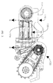
- FIGS 7 and 8 illustrate the head unit 130. It includes a frame section 132, an excavation assembly 140, and positioning assembly 170.
- the excavation assembly 140 comprises a center excavation chain 142, drive sprockets 144, driven sprockets 146 mounted on drums 148 which are rotatably mounted on head shaft 150 that is fixedly supported by extendable end section 152 of frame 132.
- the centerline of head shaft 150 defines the excavation head shaft axis 151.
- Power is transferred from the excavation hydraulic motors 52, that have been mounted onto the frame section 132 of head unit 130.
- Drive sprockets 144 are mounted onto motor shaft 145 which is supported in bearing assemblies 133 supported by frame 132.
- Hydraulic motors 52 are mounted onto motor shaft 145 and held from rotating by torque arms 53 as illustrated in Figure 9.
- the drive sprockets 144 propel the excavation chain 142 which subsequently powers rotation of the sprockets 146.
- Sprockets 146 are fixedly mounted onto drums 148 such that whenever the sprocket rotates, the drums are also rotated.
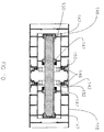
- the excavation drums 148 are rotatably mounted onto head shaft 150 by bearings 147, as illustrated in Figure 10.
- the extendible end section 152 is attached to the frame section 132 at joint 153.
- Joint 153 allows the extendible end section 152 to be moved perpendicular to the axis of rotation of the output shaft of drive motor 52 such that the distance between the drive sprockets 144 and the driven sprockets 146 can be adjusted to control chain tension.
- Excavation chain 142 comprises external flanged side bars 141 and internal side bars 143 and rollers 143a, as illustrated in Fig 11, and base plates 156, as illustrated in Fig 12.
- Base plates 156 are typically bolted to the external flanged side bars 141 with bolts 158 and nuts 159 and include mounts 155 for supporting cutters 154.
- Cutters 154 are known in a variety of configurations. It is well known to attach such cutters to chain. Similar cutters are also known to be attached to rotatable drums. The type of cutter or method of mounting are not a portion of this invention, and any such cutter or mount would be useful.
- Fig 13 illustrates the outer circumference of the two excavation drums 148 shown as 148R and 148L, corresponding to one drum on the left and one on the right, along with the base plates 156 of the excavation chain 142.
- the pattern of the cutters 154, their location and placement and the coordination of this placement for the three separate components, has been found to be critical in optimizing the excavation efficiency of the assembly.
- One aspect includes the arrangement of the cutters 154 into rows 160 and columns 162.
- the columns 162 are parallel to the excavation axis, and spaced to coincide with the base plates 156.
- column 162a contacts the ground surface first followed by 162b, followed by 162c etc.
- the first cutter 154a is on column 162h. As the chain and drums are rotated this first cutter 154a will contact the ground surface, fracturing the surface and creating a groove.
- the second cutter 154b is longitudinally spaced, away from the center of the base plate 156, towards the outer edge, as compared to the first cutter 154a. This longitudinal spacing defines the angle of the rows 160. The material contacted by the second cutter 154b will have been previously affected by the first cutter 154a on one side while on the other side the material will be less affected by any previous cutters.
- the speed of the outer surface of excavation chain 142 must be coordinated with the speed of the outer surface of the drums 148R and 148L in order to maintain the relationship between the cutters mounted to the chain and the cutters mounted to the drums.
- the drums are sized to a specific outer diameter such that the one revolution of the excavation chain results in exactly an integer number of revolutions of the excavation drums.
- the pattern shown as 148R includes 28 cutters 154 and represents one complete rotation of the excavation drum 148.
- the pattern shown in Fig. 13 represents exactly 1/2, 1/3, or 1/4 of the total length of the chain. Looking at an individual column there are always six cutters in each column, two on drum 148L, two on excavation chain 142 and two on drum 148R.
- This cutter spacing and the coordination of the excavation chain length with outer diameter of the excavation drums results in consistent placement of the cutters 154 on the excavation drums relative to the cutters 154 on the excavation chain 142.
- Many patterns can be developed, the disclosed pattern comprising a V wherein the legs of the V-pattern pass from the chain to each of the drums, is one example but many others are possible.
- the track trencher with the new excavation boom of the present invention is useful in surface mining or in surface preparation for road construction.
- the use of the track trencher for these applications is enhanced by the fact that the excavation assembly 140 always cuts wider than the tracks.
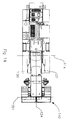
- One configuration is illustrated in Figure 14 where the excavation assembly 140 is positioned with the excavation axis 151 parallel to the main pivot axis 114.
- FIG. 15 Another configuration is illustrated in Figure 15 where the excavation assembly is tilted to its extreme position and excavation axis 151 is at the maximum angle to the tracks 20.
- the swivel or tilt axis 124 is parallel to the longitudinal axis of the machine. Even in this extreme position the drum 148 will excavate wider than the tracks 20.
Landscapes
- Engineering & Computer Science (AREA)
- Mining & Mineral Resources (AREA)
- Civil Engineering (AREA)
- General Engineering & Computer Science (AREA)
- Structural Engineering (AREA)
- Mechanical Engineering (AREA)
- Earth Drilling (AREA)
Abstract
Description
Claims (18)
- An excavating apparatus having a prime mover with a longitudinal centerline and comprising a main frame (30) with an engine, a ground drive system and an excavation boom operatively attached thereto, said excavation boom comprising:wherein said head shaft (150) is operatively pivotally attached to the second end of said sub-frame (112) along an axis (124) which is fixed with respect to said main frame pivot axis (114) and which is substantially perpendicular to said main frame pivot axis (114) whereby the position of the head shaft axis (151) can be adjusted with respect to the position of the main frame pivot axis (114) from a position parallel to said main frame pivot axis (114) to positions not parallel to said main frame pivot axis (114).a sub-frame (112) having a first end and a second end, said first end of said sub-frame (112) being operatively pivotally attached to said main frame (30) along a main frame pivot axis (114), said main frame pivot axis being transverse to the longitudinal centerline of said prime mover;a head shaft (150) operatively rotatably attached to the second end of said sub-frame (112) along a head shaft axis (151), said head shaft axis (151) being transverse to the longitudinal centerline of the prime mover;an excavating drum (148) being operatively attached to said head shaft (150) for rotation about said head shaft axis (151); and
- The excavating apparatus of claim 1 wherein said excavating drum is wider than the ground supports.
- An excavating apparatus having a prime mover having a longitudinal centerline and comprising a main frame (30) with an engine, a ground drive system and an excavation boom operatively attached thereto, said excavation boom comprising:wherein said head shaft (150) is operatively pivotally attached to the second end of said sub-frame (112) along an axis (124a of Fig. 6) which is fixed with respect to said main frame pivot axis (114) and which is substantially parallel to an axis (124) perpendicular to said main frame pivot axis (114) whereby the position of the head shaft axis (151) can be adjusted with respect to the position of the main frame pivot axis (114) from a position parallel to said main frame pivot axis (114) to positions not parallel to said main frame pivot axis (114).a sub-frame (112) having a first end and a second end, said first end of said sub-frame (112) being operatively pivotally attached to said main frame (30) along a main frame pivot axis (114), said main frame pivot axis being transverse to the longitudinal centerline of said prime mover;a head shaft (150) operatively rotatably attached to the second end of said sub-frame (112) along a head shaft axis (151), said head shaft axis (151) being transverse to the longitudinal centerline of the prime mover;an excavating drum (148) being operatively attached to said head shaft (150) for rotation about said head shaft axis (151); and
- The excavating apparatus of claim 3 wherein said excavating drum is wider than the ground drive system.
- An excavation assembly comprising;wherein the excavation drum (148) is mounted onto the head shaft (150) in a manner that the excavation drum (148) cooperates with the excavation chain (142)and the fixed cutter pattern of the excavation chain (142) to stay in consistent alignment with the fixed cutter pattern of the excavation drum (148).a frame (112) with a first and second end;a drive component (52) operatively mounted at the first end;a head shaft (150) disposed along an axis and being operatively mounted at the second end;a drive sprocket (144) operatively mounted to the drive component (52);an excavation drum (148) operatively rotatably mounted onto the head shaft (150) and including excavation members (154) operatively mounted in a fixed pattern;a driven sprocket (146) operatively mounted to the excavation drum (148);an excavation chain (142) routed around both the drive sprocket (144) and the driven sprocket (146) for transferring power from drive component (52) to excavation drum (148) and including excavation members (154) mounted in a fixed pattern;
- The excavating assembly of claim 5 including a first second and third cutters (154) wherein the first cutter is closer to a longitudinal centerline of the frame than the second cutter and the second cutter is closer to a longitudinal centerline of the frame than the third cutter.
- The excavating assembly of claim 5 wherein said first second and third cutters are in alignment along a substantially straight line.
- The excavating assembly of claim 5 including fourth, fifth and sixth cutters (154) on the other side of the longitudinal centerline from the first, second and third cutters and wherein the fourth cutter is closer to a longitudinal centerline of the frame than the fifth cutter and the fifth cutter is closer to a longitudinal centerline of the frame than the sixth cutter.
- The excavating assembly of claim 8 wherein the fourth, fifth and sixth cutters are in alignment along a substantially straight line.
- The excavating assembly of claim 9 wherein the first and fourth cutters are disposed along a line substantially parallel to the axis of the head shaft (150).
- The excavating assembly of claim 10 wherein the second and fifth cutters are disposed along a line substantially parallel to the axis of the head shaft (150).
- The excavating assembly of claim 11 wherein the third and sixth cutters are disposed along a line substantially parallel to the axis of the head shaft (150).
- The excavating assembly of claim 9 wherein the first and fourth cutters are disposed along a line substantially parallel to the axis of the head shaft (150).
- The excavating assembly of claim 13 wherein the second and fifth cutters are disposed along a line substantially parallel to the axis of the head shaft (150).
- The excavating assembly of claim 14 wherein the third and sixth cutters are disposed along a line substantially parallel to the axis of the head shaft (150).
- The excavating assembly of claim 15 wherein the first second and third cutters are in alignment along a substantially straight line.
- The excavating assembly of claim 16 wherein an additional set of cutters is disposed along an outer line parallel to an inner line passing through the first second and third cutters.
- The excavating assembly of claim 17 wherein a further set of cutters is disposed along a second outer line parallel to a second inner line passing through the fourth, fifth and sixth cutters.
Applications Claiming Priority (4)
| Application Number | Priority Date | Filing Date | Title |
|---|---|---|---|
| US227838 | 1999-01-11 | ||
| US31659001P | 2001-08-31 | 2001-08-31 | |
| US316590P | 2001-08-31 | ||
| US10/227,838 US6725579B2 (en) | 2001-08-31 | 2002-08-27 | Excavation apparatus |
Publications (3)
| Publication Number | Publication Date |
|---|---|
| EP1288376A2 true EP1288376A2 (en) | 2003-03-05 |
| EP1288376A3 EP1288376A3 (en) | 2003-04-02 |
| EP1288376B1 EP1288376B1 (en) | 2010-10-06 |
Family
ID=26921806
Family Applications (1)
| Application Number | Title | Priority Date | Filing Date |
|---|---|---|---|
| EP02405748A Expired - Lifetime EP1288376B1 (en) | 2001-08-31 | 2002-08-30 | Excavation apparatus |
Country Status (3)
| Country | Link |
|---|---|
| US (2) | US6725579B2 (en) |
| EP (1) | EP1288376B1 (en) |
| DE (1) | DE60237868D1 (en) |
Cited By (4)
| Publication number | Priority date | Publication date | Assignee | Title |
|---|---|---|---|---|
| WO2011008694A3 (en) * | 2009-07-13 | 2011-04-28 | Vermeer Manufacturing Company | Shear resistant excavation component |
| EP3070206A1 (en) * | 2015-03-16 | 2016-09-21 | Vermeer Manufacturing Company | Wide-end trencher boom |
| CN109208672A (en) * | 2018-09-20 | 2019-01-15 | 徐州徐工基础工程机械有限公司 | A kind of winding steel wire rope automatic tension control system and diaphragm wall grab machine |
| CN114562270A (en) * | 2022-02-23 | 2022-05-31 | 广东工业大学 | Star soil tunneling robot |
Families Citing this family (11)
| Publication number | Priority date | Publication date | Assignee | Title |
|---|---|---|---|---|
| US7186059B2 (en) * | 2003-04-22 | 2007-03-06 | Tommy Barnes | Padding machine and method of use |
| US7409785B2 (en) | 2004-10-12 | 2008-08-12 | Vermeer Manufacturing Company | Cutting element supported on a chain |
| US6839991B2 (en) * | 2003-05-23 | 2005-01-11 | Vermeer Manufacturing Company | Cylindrical cutting element supported on a chain |
| US20060272183A1 (en) * | 2005-06-06 | 2006-12-07 | Craig Kergen | Ground-clearing apparatus |
| EP2122069B1 (en) | 2007-02-14 | 2012-06-06 | Herbert Staubli | Ground-working machine |
| WO2010117372A1 (en) | 2009-04-09 | 2010-10-14 | Vermeer Manufacturing Company | Work machine attachment based speed control system |
| WO2012045327A1 (en) * | 2010-10-08 | 2012-04-12 | Simex Engineering S.R.L. | Cutter heads for ground or walls cutter machines and cutter machines provided with such cutter heads |
| US9103099B2 (en) | 2011-03-21 | 2015-08-11 | Vermeer Manufacturing Company | Surface excavation machine |
| WO2012142560A2 (en) * | 2011-04-14 | 2012-10-18 | Vermeer Manufacturing Company | Cab suspension for a machine adapted to surface excavate rock or like materials |
| US10138617B2 (en) * | 2016-08-12 | 2018-11-27 | The Charles Machine Works, Inc. | Ground-engageable attachment for a vehicle |
| US11788250B2 (en) | 2019-07-29 | 2023-10-17 | Great Plains Manufacturing, Inc. | Loader with improved arm path |
Family Cites Families (12)
| Publication number | Priority date | Publication date | Assignee | Title |
|---|---|---|---|---|
| DE1009157B (en) | 1955-12-31 | 1957-05-29 | Und Eisengiesserei A Heinen G | Peat excavator |
| DE1283165B (en) | 1960-11-10 | 1968-11-14 | Eberhardt Geb | Trenching machine with an excavator unit |
| US3266179A (en) | 1963-08-23 | 1966-08-16 | Norman R Golden | Digging attachment |
| IE34028B1 (en) * | 1970-02-23 | 1975-01-08 | Heidemaatschappij Beheer Nv | Apparatus for digging a trench |
| US3683522A (en) | 1970-04-13 | 1972-08-15 | Louis Rousseau | Frustoconical rotary cutter for digging trenches |
| US4164082A (en) | 1977-10-11 | 1979-08-14 | Watson Gary Q | Excavator for anchor holes |
| DE3207104A1 (en) | 1982-02-27 | 1983-09-08 | Gewerkschaft Eisenhütte Westfalia, 4670 Lünen | Trench cutting machine |
| EP0407934B1 (en) | 1989-07-10 | 1993-10-13 | TREVI S.p.A. | Method for executing monolithic continuous straights or circular structural walls and a machine for realizing such a method |
| US5199195A (en) | 1989-10-10 | 1993-04-06 | Scordilis Frank P | Articulated toothed excavating apparatus |
| GB9110798D0 (en) | 1991-05-18 | 1991-07-10 | Webster Machine Company Limite | Mechanism for supporting an earthworking etc tool |
| DE19858151A1 (en) | 1998-12-16 | 2000-06-21 | Heilit & Woerner Bau Ag | Excavator for ditches and embankments has a cutting attachment fitted to the arm of a conventional excavator and with adjustment to angle the cutting head |
| DE10019748C1 (en) | 2000-04-20 | 2001-09-20 | Man Takraf Foerdertechnik Gmbh | Device, to test ability to cut and mine critical material, has two-track running gear, frame with drive assembly, control platform and horizontal cutting roller connected to conveyor |
-
2002
- 2002-08-27 US US10/227,838 patent/US6725579B2/en not_active Expired - Lifetime
- 2002-08-30 EP EP02405748A patent/EP1288376B1/en not_active Expired - Lifetime
- 2002-08-30 DE DE60237868T patent/DE60237868D1/en not_active Expired - Lifetime
-
2004
- 2004-01-22 US US10/762,406 patent/US6948265B2/en not_active Expired - Lifetime
Cited By (9)
| Publication number | Priority date | Publication date | Assignee | Title |
|---|---|---|---|---|
| WO2011008694A3 (en) * | 2009-07-13 | 2011-04-28 | Vermeer Manufacturing Company | Shear resistant excavation component |
| CN102498248A (en) * | 2009-07-13 | 2012-06-13 | 维米尔制造公司 | Shear Resistant Digging Components |
| EP3070206A1 (en) * | 2015-03-16 | 2016-09-21 | Vermeer Manufacturing Company | Wide-end trencher boom |
| CN105986586A (en) * | 2015-03-16 | 2016-10-05 | 维米尔制造公司 | Wide-end trencher boom |
| US10407863B2 (en) | 2015-03-16 | 2019-09-10 | Vermeer Manufacturing Company | Wide-end trencher boom |
| CN109208672A (en) * | 2018-09-20 | 2019-01-15 | 徐州徐工基础工程机械有限公司 | A kind of winding steel wire rope automatic tension control system and diaphragm wall grab machine |
| CN109208672B (en) * | 2018-09-20 | 2020-11-24 | 徐州徐工基础工程机械有限公司 | Automatic tensioning control system for winch steel wire rope and continuous wall grab bucket machine |
| CN114562270A (en) * | 2022-02-23 | 2022-05-31 | 广东工业大学 | Star soil tunneling robot |
| CN114562270B (en) * | 2022-02-23 | 2024-05-03 | 广东工业大学 | Star soil tunneling robot |
Also Published As
| Publication number | Publication date |
|---|---|
| US20040172864A1 (en) | 2004-09-09 |
| EP1288376A3 (en) | 2003-04-02 |
| DE60237868D1 (en) | 2010-11-18 |
| US6948265B2 (en) | 2005-09-27 |
| EP1288376B1 (en) | 2010-10-06 |
| US20030041487A1 (en) | 2003-03-06 |
| US6725579B2 (en) | 2004-04-27 |
Similar Documents
| Publication | Publication Date | Title |
|---|---|---|
| US7290360B2 (en) | Excavation apparatus | |
| EP1288376B1 (en) | Excavation apparatus | |
| CN101575973B (en) | Mining machine with driven disc cutters | |
| US6561590B2 (en) | Cutting device with rotating disc | |
| RU2749518C2 (en) | Mining machine with multiple cutting heads | |
| US6729050B2 (en) | Control of excavation apparatus | |
| KR20030045131A (en) | Trenching method and apparatus | |
| JP6429098B2 (en) | Excavator using excavator | |
| WO2021179063A1 (en) | Underground excavation machine and method | |
| US7152348B2 (en) | Excavation apparatus | |
| WO2007035400A2 (en) | Link and chain for rock cutting | |
| US4432584A (en) | Trenching machine for cutting preferably frozen ground | |
| WO2002032798A1 (en) | Scoop wheel excavator | |
| WO2001023157A2 (en) | Method and apparatus for quarrying rock | |
| JP3963566B2 (en) | Cutter head and obstacle cutting method | |
| KR101874708B1 (en) | Non-vibration tunnel excavation method and non-vibration tunnel excavator | |
| JP3043501B2 (en) | Drilling hole forming method and forming apparatus for thin film wall formation | |
| US20240309761A1 (en) | A cutting head assembly | |
| CN87104712A (en) | Mobile Units for Surface Mining | |
| JP4520571B2 (en) | Groove cutting machine and rock cutting method using it | |
| JPH09291509A (en) | Drilling end mill and drilling equipment | |
| JP2007056647A (en) | Excavating apparatus using full slewing machine | |
| AU749078B2 (en) | Cutting device | |
| SU1724815A1 (en) | Soil slotter | |
| JPH05141180A (en) | Tunnel widening method and excavating machine therefor |
Legal Events
| Date | Code | Title | Description |
|---|---|---|---|
| PUAI | Public reference made under article 153(3) epc to a published international application that has entered the european phase |
Free format text: ORIGINAL CODE: 0009012 |
|
| PUAL | Search report despatched |
Free format text: ORIGINAL CODE: 0009013 |
|
| AK | Designated contracting states |
Kind code of ref document: A2 Designated state(s): AT BE BG CH CY CZ DE DK EE ES FI FR GB GR IE IT LI LU MC NL PT SE SK TR Designated state(s): AT BE BG CH CY CZ DE DK EE ES FI FR GB GR IE IT LI LU MC NL PT SE SK TR |
|
| AX | Request for extension of the european patent |
Extension state: AL LT LV MK RO SI |
|
| AK | Designated contracting states |
Kind code of ref document: A3 Designated state(s): AT BE BG CH CY CZ DE DK EE ES FI FR GB GR IE IT LI LU MC NL PT SE SK TR Designated state(s): AT BE BG CH CY CZ DE DK EE ES FI FR GB GR IE IT LI LU MC NL PT SE SK TR |
|
| AX | Request for extension of the european patent |
Extension state: AL LT LV MK RO SI |
|
| 17P | Request for examination filed |
Effective date: 20030731 |
|
| AKX | Designation fees paid |
Designated state(s): DE IT |
|
| 17Q | First examination report despatched |
Effective date: 20080111 |
|
| GRAP | Despatch of communication of intention to grant a patent |
Free format text: ORIGINAL CODE: EPIDOSNIGR1 |
|
| GRAS | Grant fee paid |
Free format text: ORIGINAL CODE: EPIDOSNIGR3 |
|
| GRAA | (expected) grant |
Free format text: ORIGINAL CODE: 0009210 |
|
| AK | Designated contracting states |
Kind code of ref document: B1 Designated state(s): DE IT |
|
| REF | Corresponds to: |
Ref document number: 60237868 Country of ref document: DE Date of ref document: 20101118 Kind code of ref document: P |
|
| PLBE | No opposition filed within time limit |
Free format text: ORIGINAL CODE: 0009261 |
|
| STAA | Information on the status of an ep patent application or granted ep patent |
Free format text: STATUS: NO OPPOSITION FILED WITHIN TIME LIMIT |
|
| 26N | No opposition filed |
Effective date: 20110707 |
|
| REG | Reference to a national code |
Ref country code: DE Ref legal event code: R097 Ref document number: 60237868 Country of ref document: DE Effective date: 20110707 |
|
| REG | Reference to a national code |
Ref country code: DE Ref legal event code: R082 Ref document number: 60237868 Country of ref document: DE Representative=s name: GRAMM, LINS & PARTNER PATENT- UND RECHTSANWAEL, DE |
|
| PGFP | Annual fee paid to national office [announced via postgrant information from national office to epo] |
Ref country code: IT Payment date: 20210818 Year of fee payment: 20 |
|
| PGFP | Annual fee paid to national office [announced via postgrant information from national office to epo] |
Ref country code: DE Payment date: 20210713 Year of fee payment: 20 |
|
| REG | Reference to a national code |
Ref country code: DE Ref legal event code: R071 Ref document number: 60237868 Country of ref document: DE |