EP1288332A2 - Vacuum processing apparatus and method for processing an object - Google Patents
Vacuum processing apparatus and method for processing an object Download PDFInfo
- Publication number
- EP1288332A2 EP1288332A2 EP02019443A EP02019443A EP1288332A2 EP 1288332 A2 EP1288332 A2 EP 1288332A2 EP 02019443 A EP02019443 A EP 02019443A EP 02019443 A EP02019443 A EP 02019443A EP 1288332 A2 EP1288332 A2 EP 1288332A2
- Authority
- EP
- European Patent Office
- Prior art keywords
- vacuum
- pressure
- load
- chamber
- transfer chamber
- Prior art date
- Legal status (The legal status is an assumption and is not a legal conclusion. Google has not performed a legal analysis and makes no representation as to the accuracy of the status listed.)
- Withdrawn
Links
Images

Classifications
-
- H—ELECTRICITY
- H10—SEMICONDUCTOR DEVICES; ELECTRIC SOLID-STATE DEVICES NOT OTHERWISE PROVIDED FOR
- H10P—GENERIC PROCESSES OR APPARATUS FOR THE MANUFACTURE OR TREATMENT OF DEVICES COVERED BY CLASS H10
- H10P72/00—Handling or holding of wafers, substrates or devices during manufacture or treatment thereof
- H10P72/04—Apparatus for manufacture or treatment
- H10P72/0441—Apparatus for sealing, encapsulating, glassing, decapsulating or the like
-
- C—CHEMISTRY; METALLURGY
- C23—COATING METALLIC MATERIAL; COATING MATERIAL WITH METALLIC MATERIAL; CHEMICAL SURFACE TREATMENT; DIFFUSION TREATMENT OF METALLIC MATERIAL; COATING BY VACUUM EVAPORATION, BY SPUTTERING, BY ION IMPLANTATION OR BY CHEMICAL VAPOUR DEPOSITION, IN GENERAL; INHIBITING CORROSION OF METALLIC MATERIAL OR INCRUSTATION IN GENERAL
- C23C—COATING METALLIC MATERIAL; COATING MATERIAL WITH METALLIC MATERIAL; SURFACE TREATMENT OF METALLIC MATERIAL BY DIFFUSION INTO THE SURFACE, BY CHEMICAL CONVERSION OR SUBSTITUTION; COATING BY VACUUM EVAPORATION, BY SPUTTERING, BY ION IMPLANTATION OR BY CHEMICAL VAPOUR DEPOSITION, IN GENERAL
- C23C14/00—Coating by vacuum evaporation, by sputtering or by ion implantation of the coating forming material
- C23C14/22—Coating by vacuum evaporation, by sputtering or by ion implantation of the coating forming material characterised by the process of coating
- C23C14/56—Apparatus specially adapted for continuous coating; Arrangements for maintaining the vacuum, e.g. vacuum locks
- C23C14/564—Means for minimising impurities in the coating chamber such as dust, moisture, residual gases
- C23C14/566—Means for minimising impurities in the coating chamber such as dust, moisture, residual gases using a load-lock chamber
-
- H—ELECTRICITY
- H10—SEMICONDUCTOR DEVICES; ELECTRIC SOLID-STATE DEVICES NOT OTHERWISE PROVIDED FOR
- H10P—GENERIC PROCESSES OR APPARATUS FOR THE MANUFACTURE OR TREATMENT OF DEVICES COVERED BY CLASS H10
- H10P72/00—Handling or holding of wafers, substrates or devices during manufacture or treatment thereof
- H10P72/04—Apparatus for manufacture or treatment
- H10P72/0402—Apparatus for fluid treatment
-
- H—ELECTRICITY
- H10—SEMICONDUCTOR DEVICES; ELECTRIC SOLID-STATE DEVICES NOT OTHERWISE PROVIDED FOR
- H10P—GENERIC PROCESSES OR APPARATUS FOR THE MANUFACTURE OR TREATMENT OF DEVICES COVERED BY CLASS H10
- H10P72/00—Handling or holding of wafers, substrates or devices during manufacture or treatment thereof
- H10P72/04—Apparatus for manufacture or treatment
- H10P72/0451—Apparatus for manufacturing or treating in a plurality of work-stations
- H10P72/0466—Apparatus for manufacturing or treating in a plurality of work-stations characterised by the construction of the load-lock chamber
-
- Y—GENERAL TAGGING OF NEW TECHNOLOGICAL DEVELOPMENTS; GENERAL TAGGING OF CROSS-SECTIONAL TECHNOLOGIES SPANNING OVER SEVERAL SECTIONS OF THE IPC; TECHNICAL SUBJECTS COVERED BY FORMER USPC CROSS-REFERENCE ART COLLECTIONS [XRACs] AND DIGESTS
- Y10—TECHNICAL SUBJECTS COVERED BY FORMER USPC
- Y10S—TECHNICAL SUBJECTS COVERED BY FORMER USPC CROSS-REFERENCE ART COLLECTIONS [XRACs] AND DIGESTS
- Y10S414/00—Material or article handling
- Y10S414/135—Associated with semiconductor wafer handling
- Y10S414/139—Associated with semiconductor wafer handling including wafer charging or discharging means for vacuum chamber
Definitions
- the present invention relates to a vacuum processing apparatus that carries out prescribed processing on the surface of an object to be processed, in a vacuum state.
- a vacuum processing apparatus provided with a plurality of vacuum processing chambers has been widely used (For example, Japanese Unexamined Patent Publication No. 2000-313959).
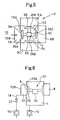
- FIG. 5 and Fig. 6 show one example of a prior art vacuum processing apparatus, respectively, wherein Fig. 5 is a plan view thereof while Fig. 6 is a longitudinally sectional view thereof.
- the vacuum processing apparatus 2 is provided with a vacuum transfer chamber 4, vacuum processing chambers 8 (8A through 8C) that, in a pressure-reduced state, carry out prescribed surface processing (film formation) on discs 6 (6A through 6D) being an object to be processed, and a load-lock chamber 12 that receives and transfers the discs 6 between the outside 10 and the vacuum transfer chamber 4.
- the vacuum transfer chamber 4 is maintained so that the interior thereof can be maintained in a vacuum state or in a pressure-reduced state (hereinafter merely called a "pressure-reduced state") by a first pump 14 .
- a turbo-molecular pump (TMP), etc. may be generally used as the first pump 14, wherein high vacuum P1 of 10 -4 Pa or so can be maintained in the vacuum transfer chamber 4.
- the above-described vacuum processing chambers 8 (8A through 8C) are provided in a plurality (in the drawing, three chambers) so as to communicate with or be isolated from the vacuum transfer chamber 4, wherein prescribed surface processing such as spattering, etc., is carried out on the discs 6 which are objects to be processed.
- the above-described load-lock chamber 12 is constructed so that the interior pressure thereof is reduced from the atmospheric pressure by a second pump 16.
- a transfer mechanism 22 for transferring the discs 6, which are the objects to be processed, is provided in the vacuum transfer chamber 4.
- the transfer mechanism 22 is composed of a rotating table 24 and a disc transfer carrier 26 that is able to hold and transfer the discs 6 attached to the corresponding rotating table 24 so as to advance and retreat.
- the disc transfer carrier 26 concurrently acts as an opening and shutting valve between the load-lock chamber 12 and the respective vacuum processing chambers 8(8A through 8C) and the above-described vacuum transfer chamber 4.
- a second opening portion 12B at the outside 10 side is opened with a first opening portion 12A with the vacuum transfer chamber 4 side closed, and the disc 6 is conveyed from the outside 10 into the load-lock chamber 12.
- the orientation of the conveyed disc 6 is turned by a rotating mechanism (not illustrated) , and the disc 6 is directly held by the disc transfer carrier 26.
- the second opening portion 12B at the outside 10 side is shut, and at the same time, the air opening and shutting valve 20 is opened, wherein the interior pressure of the load-lock chamber 12 is reduced from the atmospheric pressure to a prescribed pressure-reduced state (medium vacuum state) P2.
- a prescribed pressure-reduced state medium vacuum state
- all the disc transfer carriers 26 retreat to the rotating table 24 side, and in this state, the rotating table 24 turns by 90 degrees in the horizontal direction. If the respective disc transfer carriers 26 are caused to advance after the rotating table 24 is turned, the load-lock chamber 12 and the respective vacuum processing chambers 8 are interrupted (isolated) again from the vacuum transfer chamber 4 (in a state where the held discs 6 are, respectively, moved to the adjacent chambers).
- the air opening and shutting valve 20 is shut, the processed discs 6 (discs turned in the order from 6D to 6A) are discharged to the outside 10 by a rotating mechanism in the load-lock chamber 12. And, new unprocessed disc 6 (6A) is mounted in the disc transfer carrier 26.
- the disc 6 is conveyed into the vacuum transfer chamber 4 and carried out therefrom via the load-lock chamber 12 in a state where the reduced pressure (high vacuum state) P1 in the vacuum processing chambers 8 is maintained.
- the interior pressure of the load-lock chamber 12 is reduced to a prescribed pressure-reduced state P2 by only the second pump 16, using a considerably long period of time (T1).
- the disc transfer carrier 26 is caused to retreat, and the first opening portion 12A is opened, wherein the discs 6 are transferred.
- the load-lock chamber is temporarily returned to the atmospheric pressure once every cycle due to its construction.
- no wide-range pump has been developed, which is able to reduce the pressure from the atmospheric pressure to a pressure-reduced state at a level required for the vacuum transfer chamber by a single unit in a short time such as several seconds. Therefore, even if the pressure is reduced with a longer period of time taken, the pressure cannot be reduced to a pressure-reduced state at a level required for the vacuum transfer chamber due to shortage in the performance of a pump.
- Remaining gas is the general term of gases emitted from the wall surface of the vacuum processing chambers and vacuum transfer chamber, substrates of objects to be processed, and formed film layers, etc.
- the remaining gas means an "adverse remaining gas", which adversely influences the quality of the surface processing, among the above.
- the remaining gas can be qualitatively decreased by lowering the pressure.
- the remaining gas cannot be smoothly decreased by only control of the pressure. If the remaining gas is increased, the quality of products will be resultantly worsened. Recently, this has become a serious problem as one of the issues concerning this type of apparatus.
- the present invention was developed in order to solve such conventional problems, and it is therefore an object of the invention to provide a vacuum processing apparatus that is able to maintain the pressure of the vacuum transfer chamber at a low level without accompanying a large increase in the costs thereof, has high exhaust(purge) performance of a remaining gas, and is able to shorten the cycle time of respective processes.
- the present invention solves the above-described problems by inventing a vacuum processing apparatus according to the construction described in the following point (1).
- a vacuum processing apparatus that, without accompanying a large increase in costs with a simple structure, is able to shorten the cycle time of respective processing while always maintaining the pressure of the vacuum transfer chamber and vacuum processing chambers at a low level, and is able to bring about high exhaust efficiency of the remaining gases.
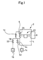
- Fig. 1 shows a first embodiment of the invention.
- a vacuum processing apparatus 50 according to the first embodiment has no special difference from the prior art vacuum processing apparatus 2 described above, other than the facility related to pressure reduction in the load-lock chamber and vacuum transfer chamber. Therefore, parts that are identical to those of the prior art vacuum processing apparatus are given the same reference numbers as those of the prior art vacuum processing apparatus, and overlapping description thereof is omitted. Herein, a detailed description is given of parts that are different from the prior art vacuum processing apparatus 2. This is the same as in the following embodiments.
- a bypass line 52 is formed between a vacuum transfer chamber 4 and a load-lock chamber 12. Also, the bypass line 52 is provided with a bypass valve 54 that opens and shuts the corresponding bypass line 52.
- the vacuum transfer chamber 4 itself will be used as a so-called accumulator.
- the bypass valve 54 is opened. Opening and shutting of the above-described bypass valve 54 are controlled by a control device 56 (Refer to Fig. 2). And, the control device 56 controls the first pump 14, the second pump 16, an air opening and shutting valve 20, and a transfer mechanism 22 (including a rotating table 24 and a disc transfer carrier 26), and is internally provided with a timer to open and shut a valve described later.
- the disc transfer carrier 26 is called the first opening and shutting valve when the load-lock chamber 12 and vacuum transfer chamber 4 are opened and shut, and is called the second opening and shutting valve when the vacuum transfer chamber 4 and vacuum processing chamber 8 are opened and shut.
- the first pump 14 for the vacuum transfer chamber 4 has a higher capacity than that of the second pump 16, it is possible to shorten the total cycle time because the first pump 14 can be used quickly. In the case of the same cycle time, a higher vacuum pressure environment can be achieved.
- the construction does not require a new pump system at all, and does not need any higher performance pump. Many of the conventional components can be used as they are, wherein it is possible to prevent costs from being increased.
- the pressure P4 of the vacuum transfer chamber immediately after the bypass valve 52 is opened by the bypass valve 52 is slightly higher than pressure P1 since a pressure-reduced state shifts to the load-lock chamber 12 side.
- the pressure of the vacuum processing chambers 8 will not rise beyond the pressure P1. Accordingly, no adverse effect due to an increase in the pressure of the vacuum transfer chamber 4 exerts on the processing in the corresponding vacuum processing chambers 8.
- exhaust speed of pump has a feature by which the further the pressure is drawn near the arrival pressure of the pump, the smaller the exhaust speed thereof becomes. Therefore, in a case where such stabilized pressure is maintained, a problem arises, by which the exhaust of the remaining gases is not rather smoothly performed. That is, it is not always most favorable, in view of exhausting the remaining gases of the vacuum transfer chamber 4, that the vacuum transfer chamber 4 is stable in a highly vacuum state where the pressure hardly changes.
- a lowering (P2 ⁇ P4) in the pressure of the load-lock chamber 12 is achieved not by strengthening the second pump but by causing the vacuum transfer chamber 4 and the load-lock chamber 12 to communicate with each other via the bypass line 54. For this reason, it is possible to cause a large amount of air to flow into the vacuum transfer chamber 4 on the basis of a greater pressure difference (P1-P3) than the pressure difference (P1-P2) in the prior arts by communication of the bypass line 54, wherein it is possible to exhaust the flown air together with the remaining gases by the first pump 14 (at a greater efficiency than in the prior arts).
- One of the timings to be selected is “the time when the pressure level (initial value P4) of the load-lock chamber 12 and vacuum transfer chamber 4, which communicate with each other, reaches pressure P1 of high vacuum required for the corresponding vacuum transfer chamber 4 (or when the time considered at which the pressure is reached elapses)", and another timing thereof is “the time immediately after surface processing in the vacuum processing chambers 8 is completed after the communication is carried out (or when the time considered at which the surface processing is completed elapses)".
- the timing when the vacuum transfer chamber 4 and vacuum processing chambers 8, which are isolated from each other, is set to "immediately after surface processing is completed in the vacuum processing chambers 8 after having communicated with each other", that is, "before the pressure of the load-lock chamber 12 and vacuum transfer chamber 4 reaches pressure P1 (or before the time considered when the pressure reaches pressure P1 elapses)", it is possible to restore the pressure to a prescribed pressure level P1 by utilizing the time during which the rotating table 24 turns by 90 degrees. Therefore, in this case, the cycle time can be further shortened.
- bypass valve 54 is shut at an optional timing until the first opening portion 12A of the load-lock chamber 12 is closed by again causing the disc transfer carrier 26 acting as the first opening and shutting valve to advance after the disc transfer carrier 26 commences retreating after prescribed processing is completed.
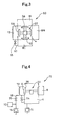
- a vacuum processing apparatus 60 In a vacuum processing apparatus 60 according to the second embodiment, an idea for improving the exhaust efficiency (air purge efficiency) is further developed. For example, taking into consideration a case where particularly adverse remaining gases frequently occur in a specified vacuum processing chamber 8 (8C in the illustrated example), as shown in Fig. 3, a second bypass line 55 that causes the corresponding vacuum processing chamber 8C and load-lock chamber 12 to communicate with each other, and a second bypass valve 57 for opening and shutting the second bypass line 55 are disposed together with the bypass line 52 (not illustrated in Fig. 3) of the preceding embodiment.
- the second bypass line 55 is constructed so as to communicate with the load-lock chamber 12 simultaneously with or with a slight delay from opening of the bypass line 52.
- the vacuum processing chamber 8C is caused to communicate with the load-lock chamber 12 (or the vacuum transfer chamber 4 connected to the load-lock chamber 12) quicker than other vacuum processing chambers 8A and 8B from an optional timing during surface processing (or immediately after surface processing) through both the bypass line 52 and the secondbypass line 55, whereby the remaining gases of the corresponding vacuum processing chamber 8C can be exhausted or (purged), taking preference over the other vacuum processing chambers 8A and 8B.
- vacuum-processing chambers 8 to be connected may be provided in a plurality.
- Avacuum processing apparatus 70 is such that, in the above-described vacuum processing apparatus 50, an accumulator chamber 72 is disposed at the second pump 16 side of the air opening and shutting valve 20 of an air line 18.
- the accumulator mechanism constructed is composed of the air opening and shutting valve 20 of the air line 18 and the accumulator chamber 72.
- the function of an accumulator is improved where the capacity of the accumulator chamber 72 is large.
- the capacity of the accumulator chamber 72 is equal to 0.5 times through 3 times the substance internal capacity of the load-lock chamber 12.
- the pressure of the accumulator chamber 72 can be reduced by rotations of the second pump 16, utilizing the time during which the second pump 16 has conventionally been uselessly rotating. Therefore, it is possible to reduce the pressure of the load-lock chamber 12 to such a level that the above-described bypass valve 54 can be opened immediately after the air opening and shutting valve 20 is opened. Also, where the above-described construction is taken into consideration only in view of accelerating the pressure reduction of the load-lock chamber 12, if the construction of this section is embodied regardless of formation of the bypass line 52, the corresponding effect of accelerating the pressure reduction can be obtained.
- the cycle time can be further shortened.
- the present invention it is possible to provide a vacuum processing apparatus that, with a simple construction and without accompanying a large increase in costs, is able to shorten the cycle times of respective processing under the condition of maintaining the pressure of a vacuum transfer chamber at a low level, and has a high exhaust effect.
Landscapes
- Chemical & Material Sciences (AREA)
- Chemical Kinetics & Catalysis (AREA)
- Engineering & Computer Science (AREA)
- Materials Engineering (AREA)
- Mechanical Engineering (AREA)
- Metallurgy (AREA)
- Organic Chemistry (AREA)
- Container, Conveyance, Adherence, Positioning, Of Wafer (AREA)
- Drying Of Semiconductors (AREA)
- Physical Vapour Deposition (AREA)
Abstract
Description
Claims (18)
- A vacuum processing apparatus including:wherein, when the atmospheric pressure in said load-lock chamber is reduced to a prescribed level with said first opening and shutting valve closed, said load-lock chamber and said vacuum transfer chamber are caused to communicate with each other by said bypass valve and said bypass line in a state where said vacuum processing chambers are isolated from said vacuum transfer chamber by said second opening and shutting valve.a vacuum transfer chamber whose interior can be maintained in a vacuum state or a pressure-reduced state;a plurality of vacuum processing chambers that are disposed adjacent to said vacuum transfer chamber so as to communicate therewith or be isolated therefrom, and carry out prescribed processing on an object to be processed, in a vacuum state or a pressure-reduced state;a load-lock chamber, the interior pressure of which is reduced from the atmospheric pressure, that carries out receiving and transfer of said object to be processed, between the outside and said vacuum transfer chamber; anda transfer mechanism, which is provided in said vacuum transfer chamber, receives said object from said load-lock chamber, and transfers said object into saidplurality of vacuum processing chambers, and at the same time, moves said object into said load-lock chamber after prescribed processing is completed;and further comprising:a bypass line for connecting said vacuum transfer chamber to said load-lock chamber;a bypass valve for opening and shutting said bypass line;a first opening and shutting valve for opening and shutting between said load-lock chamber and said vacuum transfer chamber; anda second opening and shutting valve for opening and shutting between said vacuum processing chambers and said vacuum transfer chamber;
- The vacuum processing apparatus according to Claim 1, wherein, at the stage where the pressure of said load-lock chamber reaches prescribed pressure required for said vacuum transfer chamber after said bypass valve is opened, said second opening and shutting valve is opened so as to clear a state where said vacuum processing chambers are isolated from said vacuum transfer chamber.
- The vacuum processing apparatus according to Claim 1, wherein, at the stage where time considered for which said load-lock chamber reaches pressure required for said vacuum transfer chamber elapses after said bypass valve is opened, said second opening and shutting valve is opened so as to clear a state where said vacuum processing chambers are isolated from said vacuum transfer chamber.
- The vacuum processing apparatus according to Claim 1, wherein, immediately after prescribed processing is completed in said vacuum processing chambers after said bypass valve is opened, said second opening and shutting valve is opened so as to clear a state where said vacuum processing chambers are isolated from said vacuum transfer chamber.
- The vacuum processing apparatus according to Claim 1, wherein, at the stage where time considered for which prescribed processing is completed in said vacuum processing chambers elapses after said bypass valve is opened, said second opening and shutting valve is opened so as to clear a state where said vacuum processing chambers are isolated from said vacuum transfer chamber.
- The vacuum processing apparatus according to any one of Claims 1 to 5, wherein said transfer mechanism is mainly composed of a rotating table and a plurality of transfer carriers that are attached to said rotating table so as to freely advance and retreat, and are able to hold and transfer said object to be processed, and said transfer carriers concurrently act as said first and second opening and shutting valves.
- The vacuum processing apparatus according to any one of Claims 1 to 6, further comprising:wherein said second bypass valve is opened after said bypass line is opened so as to cause said second bypass line to communicate with said load-lock chamber.a second bypass line for causing a specified vacuum processing chamber of said plurality of vacuum processing chambers to communicate with said load-lock chamber; anda second bypass valve for opening and shutting said second bypass line;
- The vacuum processing apparatus according to any one of Claims 1 to 7, wherein an opening and shutting valve for opening and shutting an air line between said load-lock chamber and a pump to reduce the pressure of said load-lock chamber is disposed in said air line; and an accumulator capable of accumulating negative pressure is disposed in said air line at said pump side of said opening and shutting valve.
- A vacuum processing apparatus including:wherein an accumulator mechanism, having at least one accumulator chamber that can be maintained in a vacuum state or a pressure-reduced state, which is able to accelerate reduction in pressure of said load-lock chamber by negative pressure of said accumulator chamber in the process of reducing the pressure inside said load-lock chamber, is provided with respect to said load-lock chamber.a vacuum transfer chamber whose interior can be maintained in a vacuum state or a pressure-reduced state;a plurality of vacuum processing chambers that are disposed adjacent to said vacuum transfer chamber so as to communicate therewith or be isolated therefrom, and carry out prescribed processing on an object to be processed, in a vacuum state or a pressure-reduced state;a load-lock chamber, the interior pressure of which is reduced from the atmospheric pressure, that carries out receiving and transfer of said object to be processed, between the outside and said vacuum transfer chamber; anda transfer mechanism, which is provided in said vacuum transfer chamber, receives said object to be processed from said load-lock chamber, and transfers said object to be processed into said plurality of vacuum processing chambers, and at the same time, moves said object into said load-lock chamber after prescribed processing is completed;
- The vacuum processing apparatus according to Claim 9, wherein the capacity of said accumulator is made 0.5 through 3 times greater than the capacity of said load-lock chamber.
- A method for producing an object to be processed, which carries out prescribed processing in a vacuum state or a pressure-reduced state, using a vacuum processing apparatus including:a vacuum transfer chamber whose interior can be maintained in a vacuum state or a pressure-reduced state;a plurality of vacuum processing chambers that are disposed adjacent to said vacuum transfer chamber so as to communicate therewith or be isolated therefrom, and carry out prescribed processing on an object to be processed, in a vacuum state or a pressure-reduced state;a load-lock chamber, the interior pressure of which is reduced from the atmospheric pressure, that carries out receiving and transfer of said object to be processed, between the outside and said vacuum transfer chamber; and a transfer mechanism, which is provided in said vacuum transfer chamber, receives said object from said load-lock chamber, and transfers said object to be processed into said plurality of vacuum processing chambers, and at the same time, carries out said object to be processed into said load-lock chamber after prescribed processing is completed;and comprising:a bypass line for connecting said vacuum transfer chamber to said load-lock chamber; anda bypass valve for opening and shutting said bypass line; and further comprising the step of:causing said load-lock chamber to communicate with said vacuum transfer chamber in a state where said vacuum processing chambers are isolated from said vacuum transfer chamber when the pressure of said load-lock chamber is reduced from the atmospheric pressure to a prescribed pressure level.
- A method for producing an object to be processed, comprising the steps of:wherein conveyance, carrying-out, receiving and transfer of said object to be processed are executed by a transfer mechanism secured in said vacuum transfer chamber, said load-lock chamber is isolated from the vacuum transfer chamber when receiving said object from the outside and transferring the same thereto, and is made to open to the atmospheric air, and said vacuum transfer chamber is interrupted from the atmospheric air when receiving said object to be processed from said vacuum transfer chamber and transferring the same thereto, and the interior pressure thereof is reduced, and said object to be processed is conveyed to said load-lock chamber after having executed prescribed processing on said object with said plurality of vacuum processing chambers made vacuum; andconveying and carrying out an object to be processed, from a vacuum transfer chamber, the interior of which can be maintained in a vacuum state or a pressure-reduced state, to a plurality of vacuum processing chambers, which are disposed adjacent to said vacuum transfer chamber so as to communicate therewith or be isolated therefrom and carry out prescribed processing with respect to said object to be processed, in a vacuum state or a pressure-reduced state;receiving and transferring said object to be processed between the outside and said vacuum transfer chamber via a load-lock chamber, the interior pressure of which is reduced from the atmospheric pressure;
when the pressure of said load-lock chamber is reduced from the atmospheric pressure to a prescribed level, said load-lock chamber is bypassed to said vacuum transfer chamber in a state where said vacuum processing chambers are isolated from said vacuum transfer chamber. - The method for producing an object to be processed, according to Claim 12, wherein, at the stage where the pressure of said load-lock chamber reaches the pressure required for said vacuum transfer chamber in the bypassed state, a state where said vacuum processing chambers are isolated from said vacuum transfer chamber is cleared.
- The method for producing an object to be processed according to Claim 12, wherein, at the stage where time considered for which said load-lock chamber reaches pressure required for said vacuum transfer chamber elapses in the bypassed state, a state where said vacuum processing chambers are isolated from said vacuum transfer chamber is cleared.
- The method for producing an object to be processed according to Claim 12, wherein, immediately after prescribed processing is completed in said vacuum processing chambers in the bypassed state, a state where said vacuum processing chambers are isolated from said vacuum transfer chamber is cleared.
- The method for producing an object to be processed according to claim 12, wherein, at the stage where time considered for which prescribed processing is completed in said vacuum processing chambers elapses in the bypassed state, a state where said vacuum processing chambers are isolated from said vacuum transfer chamber is cleared.
- The method for producing an object to be processed according to any one of Claims 12 to 16, wherein at least a part of said plurality of vacuum processing chambers is bypassed to said load-lock chamber simultaneously with commencement of the bypassed state or immediately thereafter.
- The method for producing an object to be processed according to anyone of Claims 12 to 16, wherein negative pressure of an accumulator that is able to accumulate negative pressure is applied to the load-lock chamber when reducing the pressure of said load-lock chamber.
Applications Claiming Priority (2)
| Application Number | Priority Date | Filing Date | Title |
|---|---|---|---|
| JP2001264193 | 2001-08-31 | ||
| JP2001264193 | 2001-08-31 |
Publications (2)
| Publication Number | Publication Date |
|---|---|
| EP1288332A2 true EP1288332A2 (en) | 2003-03-05 |
| EP1288332A3 EP1288332A3 (en) | 2004-04-21 |
Family
ID=19090841
Family Applications (1)
| Application Number | Title | Priority Date | Filing Date |
|---|---|---|---|
| EP02019443A Withdrawn EP1288332A3 (en) | 2001-08-31 | 2002-08-30 | Vacuum processing apparatus and method for processing an object |
Country Status (3)
| Country | Link |
|---|---|
| US (2) | US6843883B2 (en) |
| EP (1) | EP1288332A3 (en) |
| TW (1) | TW556189B (en) |
Families Citing this family (6)
| Publication number | Priority date | Publication date | Assignee | Title |
|---|---|---|---|---|
| JP4653419B2 (en) | 2004-05-17 | 2011-03-16 | 芝浦メカトロニクス株式会社 | Vacuum processing equipment |
| JP5031473B2 (en) * | 2007-07-25 | 2012-09-19 | 株式会社ソニーDadc | Vacuum transfer device, vacuum transfer method |
| US20100021273A1 (en) * | 2008-07-28 | 2010-01-28 | Applied Materials, Inc. | Concrete vacuum chamber |
| KR101171990B1 (en) * | 2011-10-05 | 2012-08-07 | (주)선린 | Vacuum processing apparatus with means preventing counter pressure between chambers |
| US10115608B2 (en) * | 2012-05-25 | 2018-10-30 | Novellus Systems, Inc. | Method and apparatus for rapid pump-down of a high-vacuum loadlock |
| US11581186B2 (en) * | 2016-12-15 | 2023-02-14 | Asm Ip Holding B.V. | Sequential infiltration synthesis apparatus |
Family Cites Families (13)
| Publication number | Priority date | Publication date | Assignee | Title |
|---|---|---|---|---|
| JPS5878357A (en) * | 1981-10-31 | 1983-05-11 | Mitsubishi Electric Corp | Electron-beam welding device |
| JPS6052574A (en) * | 1983-09-02 | 1985-03-25 | Hitachi Ltd | Continuous sputtering device |
| US4699585A (en) * | 1984-09-28 | 1987-10-13 | Kautex-Werke Reinold Hagen Ag | Blow molding apparatus |
| JPS6450414A (en) * | 1987-08-21 | 1989-02-27 | Hitachi Ltd | Vacuum treatment apparatus |
| DE3731444A1 (en) * | 1987-09-18 | 1989-03-30 | Leybold Ag | DEVICE FOR COATING SUBSTRATES |
| JPH0281457A (en) * | 1988-09-16 | 1990-03-22 | Canon Inc | retention system |
| JP3186262B2 (en) * | 1992-10-14 | 2001-07-11 | ソニー株式会社 | Method for manufacturing semiconductor device |
| DE4401718C1 (en) | 1994-01-21 | 1995-08-17 | Anke Gmbh & Co Kg | Method and appts. for treatment of workpieces in a vacuum atmosphere |
| JP2887079B2 (en) | 1994-09-29 | 1999-04-26 | 芝浦メカトロニクス株式会社 | Ashing equipment |
| JPH11186363A (en) * | 1997-12-24 | 1999-07-09 | Shin Etsu Handotai Co Ltd | Semiconductor manufacturing equipment |
| CA2367204A1 (en) * | 1999-03-19 | 2000-09-28 | Electron Vision Corporation | Cluster tool for wafer processing having an electron beam exposure module |
| JP4166902B2 (en) | 1999-04-27 | 2008-10-15 | 芝浦メカトロニクス株式会社 | Vacuum processing equipment |
| JP3676983B2 (en) * | 2000-03-29 | 2005-07-27 | 株式会社日立国際電気 | Semiconductor manufacturing method, substrate processing method, and semiconductor manufacturing apparatus |
-
2002
- 2002-08-29 US US10/230,178 patent/US6843883B2/en not_active Expired - Fee Related
- 2002-08-30 EP EP02019443A patent/EP1288332A3/en not_active Withdrawn
- 2002-08-30 TW TW091119890A patent/TW556189B/en not_active IP Right Cessation
-
2004
- 2004-12-02 US US11/000,882 patent/US20050092251A1/en not_active Abandoned
Also Published As
| Publication number | Publication date |
|---|---|
| US20030051815A1 (en) | 2003-03-20 |
| US20050092251A1 (en) | 2005-05-05 |
| EP1288332A3 (en) | 2004-04-21 |
| US6843883B2 (en) | 2005-01-18 |
| TW556189B (en) | 2003-10-01 |
Similar Documents
| Publication | Publication Date | Title |
|---|---|---|
| US6053686A (en) | Device and method for load locking for semiconductor processing | |
| JP3486821B2 (en) | Processing apparatus and method of transporting object to be processed in processing apparatus | |
| KR102385670B1 (en) | Substrate transfer method and substrate processing apparatus | |
| KR890002837B1 (en) | Continuous sputtering apparatus | |
| US8246284B2 (en) | Stacked load-lock apparatus and method for high throughput solar cell manufacturing | |
| CN100520503C (en) | Vacuum pumping system, driving method thereof, apparatus having the same, and method of transferring substrate by using the system | |
| JP4054003B2 (en) | Inline coating equipment operation method | |
| US6251192B1 (en) | Vacuum exhaust system | |
| US20070051314A1 (en) | Movable transfer chamber and substrate-treating apparatus including the same | |
| JP4472005B2 (en) | Vacuum processing apparatus and vacuum processing method | |
| US6990747B2 (en) | Vacuum processing apparatus and substrate transfer method | |
| US6843883B2 (en) | Vacuum processing apparatus and method for producing an object to be processed | |
| US20040089227A1 (en) | Dual chamber vacuum processing system | |
| US20070175395A1 (en) | Semiconductor device manufacturing equipment including a vacuum apparatus and a method of operating the same | |
| JP2005019739A (en) | Method for transporting workpieces | |
| JP2009065068A (en) | Substrate processing apparatus, contamination control method for substrate processing apparatus, and storage medium | |
| JP6463846B2 (en) | Method for operating inline coating equipment and inline coating equipment | |
| KR101173571B1 (en) | Vacuum pumping system of substrate processing apparatus and method of vacuum pumping transfer chamber using the same | |
| JP2014195008A (en) | Vacuum treatment apparatus and method for operating vacuum treatment apparatus | |
| JPH11230034A (en) | Evacuating system and its operating method | |
| KR20060043107A (en) | Vacuum pumping system and method and process equipment using same | |
| KR101626467B1 (en) | Substrate tretment apparatus | |
| KR101208696B1 (en) | apparatus for producing semiconductor and method for controlling chamber thereof | |
| JP3025811B2 (en) | Substrate processing equipment | |
| KR20100089312A (en) | Loadlock chamber in a semi-conductor manufacturing system |
Legal Events
| Date | Code | Title | Description |
|---|---|---|---|
| PUAI | Public reference made under article 153(3) epc to a published international application that has entered the european phase |
Free format text: ORIGINAL CODE: 0009012 |
|
| AK | Designated contracting states |
Kind code of ref document: A2 Designated state(s): AT BE BG CH CY CZ DE DK EE ES FI FR GB GR IE IT LI LU MC NL PT SE SK TR Designated state(s): AT BE BG CH CY CZ DE DK EE ES FI FR GB GR IE IT LI LU MC NL PT SE SK TR |
|
| AX | Request for extension of the european patent |
Extension state: AL LT LV MK RO SI |
|
| PUAL | Search report despatched |
Free format text: ORIGINAL CODE: 0009013 |
|
| AK | Designated contracting states |
Kind code of ref document: A3 Designated state(s): AT BE BG CH CY CZ DE DK EE ES FI FR GB GR IE IT LI LU MC NL PT SE SK TR |
|
| AX | Request for extension of the european patent |
Extension state: AL LT LV MK RO SI |
|
| 17P | Request for examination filed |
Effective date: 20041020 |
|
| AKX | Designation fees paid |
Designated state(s): AT BE BG CH CY CZ DE DK EE ES FI FR GB GR IE IT LI LU MC NL PT SE SK TR |
|
| STAA | Information on the status of an ep patent application or granted ep patent |
Free format text: STATUS: THE APPLICATION HAS BEEN WITHDRAWN |
|
| 18W | Application withdrawn |
Effective date: 20060811 |