EP1288094A1 - Electric caliper having splined ball screw - Google Patents
Electric caliper having splined ball screw Download PDFInfo
- Publication number
- EP1288094A1 EP1288094A1 EP02078091A EP02078091A EP1288094A1 EP 1288094 A1 EP1288094 A1 EP 1288094A1 EP 02078091 A EP02078091 A EP 02078091A EP 02078091 A EP02078091 A EP 02078091A EP 1288094 A1 EP1288094 A1 EP 1288094A1
- Authority
- EP
- European Patent Office
- Prior art keywords
- ball screw
- assembly
- carrier
- screw assembly
- electric
- Prior art date
- Legal status (The legal status is an assumption and is not a legal conclusion. Google has not performed a legal analysis and makes no representation as to the accuracy of the status listed.)
- Withdrawn
Links
- 239000012530 fluid Substances 0.000 description 4
- 238000005096 rolling process Methods 0.000 description 2
- 238000004519 manufacturing process Methods 0.000 description 1
- 230000013011 mating Effects 0.000 description 1
- 238000012986 modification Methods 0.000 description 1
- 230000004048 modification Effects 0.000 description 1
- 238000004806 packaging method and process Methods 0.000 description 1
- 230000037361 pathway Effects 0.000 description 1
Images

Classifications
-
- F—MECHANICAL ENGINEERING; LIGHTING; HEATING; WEAPONS; BLASTING
- F16—ENGINEERING ELEMENTS AND UNITS; GENERAL MEASURES FOR PRODUCING AND MAINTAINING EFFECTIVE FUNCTIONING OF MACHINES OR INSTALLATIONS; THERMAL INSULATION IN GENERAL
- F16D—COUPLINGS FOR TRANSMITTING ROTATION; CLUTCHES; BRAKES
- F16D65/00—Parts or details
- F16D65/14—Actuating mechanisms for brakes; Means for initiating operation at a predetermined position
- F16D65/16—Actuating mechanisms for brakes; Means for initiating operation at a predetermined position arranged in or on the brake
- F16D65/18—Actuating mechanisms for brakes; Means for initiating operation at a predetermined position arranged in or on the brake adapted for drawing members together, e.g. for disc brakes
-
- F—MECHANICAL ENGINEERING; LIGHTING; HEATING; WEAPONS; BLASTING
- F16—ENGINEERING ELEMENTS AND UNITS; GENERAL MEASURES FOR PRODUCING AND MAINTAINING EFFECTIVE FUNCTIONING OF MACHINES OR INSTALLATIONS; THERMAL INSULATION IN GENERAL
- F16D—COUPLINGS FOR TRANSMITTING ROTATION; CLUTCHES; BRAKES
- F16D2121/00—Type of actuator operation force
- F16D2121/18—Electric or magnetic
- F16D2121/24—Electric or magnetic using motors
-
- F—MECHANICAL ENGINEERING; LIGHTING; HEATING; WEAPONS; BLASTING
- F16—ENGINEERING ELEMENTS AND UNITS; GENERAL MEASURES FOR PRODUCING AND MAINTAINING EFFECTIVE FUNCTIONING OF MACHINES OR INSTALLATIONS; THERMAL INSULATION IN GENERAL
- F16D—COUPLINGS FOR TRANSMITTING ROTATION; CLUTCHES; BRAKES
- F16D2125/00—Components of actuators
- F16D2125/18—Mechanical mechanisms
- F16D2125/20—Mechanical mechanisms converting rotation to linear movement or vice versa
- F16D2125/34—Mechanical mechanisms converting rotation to linear movement or vice versa acting in the direction of the axis of rotation
- F16D2125/40—Screw-and-nut
-
- F—MECHANICAL ENGINEERING; LIGHTING; HEATING; WEAPONS; BLASTING
- F16—ENGINEERING ELEMENTS AND UNITS; GENERAL MEASURES FOR PRODUCING AND MAINTAINING EFFECTIVE FUNCTIONING OF MACHINES OR INSTALLATIONS; THERMAL INSULATION IN GENERAL
- F16D—COUPLINGS FOR TRANSMITTING ROTATION; CLUTCHES; BRAKES
- F16D2125/00—Components of actuators
- F16D2125/18—Mechanical mechanisms
- F16D2125/44—Mechanical mechanisms transmitting rotation
- F16D2125/46—Rotating members in mutual engagement
- F16D2125/50—Rotating members in mutual engagement with parallel non-stationary axes, e.g. planetary gearing
Definitions
- the present invention relates generally to brakes for motor vehicles, and more particularly to an electric caliper for a brake system in a motor vehicle.
- a brake system for a motor vehicle functionally reduces the speed of the vehicle or maintains the vehicle in a rest position.
- Various types of brake systems are commonly used in automotive vehicles, including hydraulic, anti-lock or "ABS,” and electric or “brake by wire.”
- ABS anti-lock
- brake by wire For example, in a hydraulic brake system, the hydraulic fluid transfers energy from a brake pedal to a brake pad for slowing down or stopping rotation of a wheel of the vehicle. Electronics control the hydraulic fluid in the hydraulic brake system. In the electric brake system, the hydraulic fluid is eliminated. Instead, the application and release of the brake pad is controlled by an electric caliper.
- hydraulic fluid is a very efficient means of transferring a load, since a brake system in an automotive vehicle must be able to transfer a load of about fourteen thousand (14,000) pounds.
- An electric brake system accomplishes this load transfer through the electric caliper.
- the electric caliper includes a motor and a gear system. Typically, either a few large gears or many small gears for the gear system are needed to achieve the necessary load transfer.
- the geometry of the motor influences its efficiency, since the preferred shape is long and thin.
- space limitations constrain the use of an electric caliper in an automotive vehicle.
- the present invention is a ball screw assembly for a motor vehicle electric caliper.
- the ball screw assembly comprises a ball screw, a carrier, and a ball screw nut.
- the ball screw has at least one internal groove, and the carrier has at least one projection engaging the at least one groove.
- the ball screw nut operatively engages the ball screw.
- an object of the present invention to provide an electric caliper for a brake system that can be packaged within the available space of a wheel.
- Another object of the present invention is to provide an electric caliper including a ball screw.
- Still another object of the present invention is to provide an electric caliper of the type described above that has a ball screw positioned around a motor which effectively increases gear reduction capability of the ball screw.
- Still another object of the present invention is to provide an electric caliper of the type described above which reduces the number of parts found in prior art electric calipers, and reduces the cost of manufacturing the remaining parts.
- Still another object of the present invention is to provide a ball screw assembly of the type described above which has a ball screw with internal splines or keyways.
- FIGS. 1 and 2 show one embodiment of an electric caliper 10 according to the present invention for a brake system such as of the disc brake type to slow or stop rotation of a wheel (not shown) of a motor vehicle.
- the brake system includes a brake pedal (not shown) which communicates a signal from a driver of the motor vehicle to the electric caliper 10.
- Rotation of a disc or rotor 11 is slowed down or stopped by engaging the electric caliper 10 which displaces a pair of resilient friction elements that engage the disc 11, as described below.
- the electric caliper 10 includes a cylindrical housing 14 having a bore 16 and an L-shaped bridge 18 extending transversely from a front end of the housing 14.
- the bridge 18 has a leg 20 to move or displace an outer brake pad 22 as will be described.
- the electric caliper 10 also includes a conventional, generally U-shaped brake pad attachment bracket 24 positioned around the bridge 18.
- the attachment bracket 24 is operatively attached to the housing 14.
- a conventional rod (not shown) interconnects the housing 14 and the attachment bracket 24 such that the housing 14 is transversely slidable along the rod, as will be described. It should be appreciated that the attachment bracket 24 is also fixedly attached to vehicle structure of the motor vehicle.
- the electric caliper 10 includes an inner brake pad 26 extending radially from an inner attachment bracket leg 28 closest to the housing 14.
- the disc 11 extends between the outer and inner brake pads 22 and 26. It should be appreciated that, in this example, the electric caliper 10 is of the floating type.
- the inner brake pad 26 engages the disc 11, and the resulting reactionary force pulls outer brake pad 22 into engagement with the disc 11. The engagement of the inner and outer brake pads with the disc 11 slows down the wheel or holds the wheel in a fixed position.
- a motor 30 is provided for controlling the engagement of the inner brake pad 26 and outer brake pad 22.
- the motor 30 is fixedly mounted within the bore 16 in the housing 14.
- positioning the motor 30 inside the housing 14 allows the selection of a motor with a more efficient geometry. In this example, a longer, thinner motor is preferable.
- the motor 30 includes an axially extending shaft 32 which drives a first stage sun gear 34.
- the sun gear 34 in turn rotatably engages a plurality of planetary gears 36.
- the planetary gears 36 are pinned to a first stage carrier 38, and travel about a ring gear 40 fixed to the housing 14.
- a second stage carrier 42 has projections 44 that extend into holes 46 on the first stage carrier 38.
- the projections 44 also carry a second set of planetary gears 48.
- One or more projections, such as splines or keys 50 are disposed around the perimeter of the second stage carrier 42.
- the keys 50 are adapted to engage mating splines or keyways 52 formed in an inner surface of a ball screw 54.
- a brake pedal is electrically connected to the electric caliper 10.
- the application of a force to the brake pedal initiates operation of the motor 30.
- the shaft 32 rotates and causes the sun gear 34 to rotate, which in turn causes the planetary gears 36 to rotate.
- the planetary gears 36 correspondingly rotate the first stage carrier 38 and the second stage carrier 42.
- the second stage carrier 42 By virtue of the engagement between the keys 50 and the keyways 52, the second stage carrier 42 in turn rotates the ball screw 54.
- the ball screw 54 includes an outer threaded screw portion 56 that operably engages a correspondingly inner threaded screw portion of a ball screw nut 58.
- the threaded screw portions cooperatively form a pathway or ball race in which rolling elements, such as spherical balls 60, may be disposed.
- a relatively large ball screw 54 is necessary to transfer a load ranging between 12,000 lb. to 15,000 lb. of force, and space within the wheel well is limited.
- the size of the ball screw 54 is effectively increased.
- the reduced pitch of the ball screw 54 and the larger number of balls increase its load carrying capability.
Landscapes
- Engineering & Computer Science (AREA)
- General Engineering & Computer Science (AREA)
- Mechanical Engineering (AREA)
- Braking Arrangements (AREA)
Abstract
Description
- The present invention relates generally to brakes for motor vehicles, and more particularly to an electric caliper for a brake system in a motor vehicle.
- A brake system for a motor vehicle, and in particular an automotive vehicle, functionally reduces the speed of the vehicle or maintains the vehicle in a rest position. Various types of brake systems are commonly used in automotive vehicles, including hydraulic, anti-lock or "ABS," and electric or "brake by wire." For example, in a hydraulic brake system, the hydraulic fluid transfers energy from a brake pedal to a brake pad for slowing down or stopping rotation of a wheel of the vehicle. Electronics control the hydraulic fluid in the hydraulic brake system. In the electric brake system, the hydraulic fluid is eliminated. Instead, the application and release of the brake pad is controlled by an electric caliper.
- Traditionally, hydraulic fluid is a very efficient means of transferring a load, since a brake system in an automotive vehicle must be able to transfer a load of about fourteen thousand (14,000) pounds. An electric brake system accomplishes this load transfer through the electric caliper. Generally, the electric caliper includes a motor and a gear system. Typically, either a few large gears or many small gears for the gear system are needed to achieve the necessary load transfer. Also, the geometry of the motor influences its efficiency, since the preferred shape is long and thin. However, there is a limited amount of space available in the wheel for packaging the type of gears or motor necessary to obtain the same load transfer as in the hydraulic brake system. Therefore, space limitations constrain the use of an electric caliper in an automotive vehicle.
- The present invention is a ball screw assembly for a motor vehicle electric caliper. The ball screw assembly comprises a ball screw, a carrier, and a ball screw nut. The ball screw has at least one internal groove, and the carrier has at least one projection engaging the at least one groove. The ball screw nut operatively engages the ball screw.
- Accordingly, it is an object of the present invention to provide an electric caliper for a brake system that can be packaged within the available space of a wheel.
- Another object of the present invention is to provide an electric caliper including a ball screw.
- Still another object of the present invention is to provide an electric caliper of the type described above that has a ball screw positioned around a motor which effectively increases gear reduction capability of the ball screw.
- Still another object of the present invention is to provide an electric caliper of the type described above which reduces the number of parts found in prior art electric calipers, and reduces the cost of manufacturing the remaining parts.
- Still another object of the present invention is to provide a ball screw assembly of the type described above which has a ball screw with internal splines or keyways.
- These and other features and advantages of the invention will become further apparent from the following detailed description of the presently preferred embodiments, read in conjunction with the accompanying drawings. The detailed description and drawings are merely illustrative of the invention rather than limiting, the scope of the invention being defined by the appended claims and equivalents thereof.
-
- FIG. 1 is a fragmentary elevational view of an electric caliper according to the present invention; and
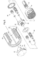
- FIG. 2 is an exploded view of a portion of the electric caliper of FIG. 1.
-
- FIGS. 1 and 2 show one embodiment of an
electric caliper 10 according to the present invention for a brake system such as of the disc brake type to slow or stop rotation of a wheel (not shown) of a motor vehicle. The brake system includes a brake pedal (not shown) which communicates a signal from a driver of the motor vehicle to theelectric caliper 10. Rotation of a disc orrotor 11 is slowed down or stopped by engaging theelectric caliper 10 which displaces a pair of resilient friction elements that engage thedisc 11, as described below. - The
electric caliper 10 includes acylindrical housing 14 having abore 16 and an L-shaped bridge 18 extending transversely from a front end of thehousing 14. Thebridge 18 has aleg 20 to move or displace anouter brake pad 22 as will be described. Theelectric caliper 10 also includes a conventional, generally U-shaped brakepad attachment bracket 24 positioned around thebridge 18. Theattachment bracket 24 is operatively attached to thehousing 14. For example, a conventional rod (not shown) interconnects thehousing 14 and theattachment bracket 24 such that thehousing 14 is transversely slidable along the rod, as will be described. It should be appreciated that theattachment bracket 24 is also fixedly attached to vehicle structure of the motor vehicle. - The
electric caliper 10 includes aninner brake pad 26 extending radially from an innerattachment bracket leg 28 closest to thehousing 14. Thedisc 11 extends between the outer andinner brake pads electric caliper 10 is of the floating type. During braking, theinner brake pad 26 engages thedisc 11, and the resulting reactionary force pullsouter brake pad 22 into engagement with thedisc 11. The engagement of the inner and outer brake pads with thedisc 11 slows down the wheel or holds the wheel in a fixed position. - A
motor 30 is provided for controlling the engagement of theinner brake pad 26 andouter brake pad 22. Themotor 30 is fixedly mounted within thebore 16 in thehousing 14. Advantageously, positioning themotor 30 inside thehousing 14 allows the selection of a motor with a more efficient geometry. In this example, a longer, thinner motor is preferable. Themotor 30 includes an axially extendingshaft 32 which drives a firststage sun gear 34. Thesun gear 34 in turn rotatably engages a plurality ofplanetary gears 36. Theplanetary gears 36 are pinned to afirst stage carrier 38, and travel about aring gear 40 fixed to thehousing 14. - A
second stage carrier 42 hasprojections 44 that extend intoholes 46 on thefirst stage carrier 38. Theprojections 44 also carry a second set ofplanetary gears 48. One or more projections, such as splines orkeys 50 are disposed around the perimeter of thesecond stage carrier 42. Thekeys 50 are adapted to engage mating splines orkeyways 52 formed in an inner surface of aball screw 54. - In operation, a brake pedal is electrically connected to the
electric caliper 10. The application of a force to the brake pedal initiates operation of themotor 30. When themotor 30 is energized, theshaft 32 rotates and causes thesun gear 34 to rotate, which in turn causes theplanetary gears 36 to rotate. Theplanetary gears 36 correspondingly rotate thefirst stage carrier 38 and thesecond stage carrier 42. By virtue of the engagement between thekeys 50 and thekeyways 52, thesecond stage carrier 42 in turn rotates theball screw 54. Theball screw 54 includes an outer threadedscrew portion 56 that operably engages a correspondingly inner threaded screw portion of aball screw nut 58. The threaded screw portions cooperatively form a pathway or ball race in which rolling elements, such asspherical balls 60, may be disposed. - Rotation of the
screw portion 56 of theball screw 54 initiates rolling of theballs 60 in the ball race to linearly displace theball screw nut 58. When theball screw nut 58 is displaced in the leftward direction as shown in FIG. 1, it in turn displaces theinner brake pad 26 against thedisc 11. The resulting pressure that builds up from theinner brake pad 26 against thedisc 11 creates a reactionary force that is transmitted back into thehousing 14 through the rod. Thehousing 14 is displaced in the direction away from thedisc 11, so that thebridge 18 pulls theouter brake pad 22 toward thedisc 11, until both theinner brake pad 26 andouter brake pad 22 are exerting pressure on thedisc 11 to slow down or stop the rotation of the wheel. Further details of this arrangement are disclosed in U.S. Patent No. 6,139,460, the disclosure of which is hereby incorporated by reference. - Typically, a relatively
large ball screw 54 is necessary to transfer a load ranging between 12,000 lb. to 15,000 lb. of force, and space within the wheel well is limited. However, by positioning theball screw 54 around themotor 30 and inside thebore 16 in thehousing 14, the size of theball screw 54 is effectively increased. Advantageously, the reduced pitch of theball screw 54 and the larger number of balls increase its load carrying capability. - While the embodiment of the invention disclosed herein is presently considered to be preferred, various changes and modifications can be made without departing from the spirit and scope of the invention. The scope of the invention is indicated in the appended claims, and all changes that come within the meaning and range of equivalents are intended to be embraced therein.
Claims (20)
- A ball screw assembly for a motor vehicle electric caliper, the ball screw assembly comprising:a ball screw having at least one internal groove;a carrier having at least one projection engaging the at least one groove; anda ball screw nut operatively engaged with the ball screw.
- The ball screw assembly of claim 1 wherein the carrier has at least one second projection, each second projection engaging a planetary gear.
- The ball screw assembly of claim 2 wherein the at least one second projection engages a first stage carrier.
- The ball screw assembly of claim 2 wherein the planetary gear engages a ring gear.
- The ball screw assembly of claim 4 wherein the ring gear is rotationally fixed relative to the ball screw.
- The ball screw assembly of claim 3 wherein the first stage carrier engages at least one second planetary gear.
- The ball screw assembly of claim 6 further comprising:an electric motor drivingly engaged with the second planetary gear.
- The ball screw assembly of claim 1 further comprising:an electric motor drivingly engaged with the carrier.
- The ball screw assembly of claim 1 wherein the groove comprises a spline.
- The ball screw assembly of claim 1 wherein the groove comprises a keyway.
- An electric caliper assembly for a motor vehicle, the electric caliper assembly comprising:a ball screw having at least one internal groove;a carrier having at least one projection engaging the at least one groove;a ball screw nut operatively engaged with the ball screw; andan electric motor drivingly engaged with the carrier.
- The ball screw assembly of claim 11 wherein the carrier has at least one second projection, each second projection engaging a planetary gear.
- The ball screw assembly of claim 12 wherein the at least one second projection engages a first stage carrier.
- The ball screw assembly of claim 12 wherein the planetary gear engages a ring gear.
- The ball screw assembly of claim 14 wherein the ring gear is rotationally fixed relative to the ball screw.
- The ball screw assembly of claim 13 wherein the first stage carrier engages at least one second planetary gear.
- The ball screw assembly of claim 11 wherein the groove comprises a spline.
- The ball screw assembly of claim 11 wherein the groove comprises a keyway.
- An electric brake assembly for a motor vehicle, the electric brake assembly comprising:a caliper adapted to frictionally engaged a rotor of the motor vehicle;a ball screw having at least one internal groove;a carrier having at least one projection engaging the at least one groove;a ball screw nut operatively engaged with the ball screw; andan electric motor drivingly engaged with the carrier and adapted to bias the caliper into frictional engagement with the rotor.
- The electric brake assembly of claim 19 wherein the groove comprises a keyway.
Applications Claiming Priority (2)
| Application Number | Priority Date | Filing Date | Title |
|---|---|---|---|
| US935117 | 2001-08-22 | ||
| US09/935,117 US6367593B1 (en) | 2001-08-22 | 2001-08-22 | Electric caliper having splined ball screw |
Publications (1)
| Publication Number | Publication Date |
|---|---|
| EP1288094A1 true EP1288094A1 (en) | 2003-03-05 |
Family
ID=25466604
Family Applications (1)
| Application Number | Title | Priority Date | Filing Date |
|---|---|---|---|
| EP02078091A Withdrawn EP1288094A1 (en) | 2001-08-22 | 2002-07-29 | Electric caliper having splined ball screw |
Country Status (2)
| Country | Link |
|---|---|
| US (1) | US6367593B1 (en) |
| EP (1) | EP1288094A1 (en) |
Families Citing this family (24)
| Publication number | Priority date | Publication date | Assignee | Title |
|---|---|---|---|---|
| NL1011142C2 (en) * | 1999-01-27 | 2000-07-31 | Skf Eng & Res Centre Bv | Compact actuator. |
| US6883635B2 (en) * | 2001-06-29 | 2005-04-26 | Delphi Technologies, Inc. | Ball-screw assembly isolator |
| US6561321B1 (en) * | 2001-12-18 | 2003-05-13 | Delphi Technologies, Inc. | Electromechanical parking brake |
| US6626270B2 (en) * | 2001-12-21 | 2003-09-30 | Delphi Technologies, Inc. | Caliper with internal motor |
| US20040083840A1 (en) * | 2002-11-04 | 2004-05-06 | King David E. | Integrated recirculation path in ball nut / ball screw |
| US20040118643A1 (en) * | 2002-12-23 | 2004-06-24 | Booher Benjamin V. | In wheel brake assembly |
| US20040159509A1 (en) * | 2003-02-14 | 2004-08-19 | Delphi Technologies, Inc. | Dual bore electric caliper with taper wear adjustment |
| US20040188193A1 (en) * | 2003-03-26 | 2004-09-30 | Delphi Technologies Inc. | Motor back drive control for electric caliper brake system |
| US20040200676A1 (en) * | 2003-04-08 | 2004-10-14 | Huang-Tsang Chang | Electric sliding disc brake system |
| US20050034936A1 (en) * | 2003-08-13 | 2005-02-17 | Delphi Technologies Inc. | Electric brake caliper having a ballscrew with integral gear carrier |
| ITTO20040871A1 (en) * | 2004-12-13 | 2005-03-13 | Skf Ab | LINEAR ELECTROMECHANICAL SCREW ACTUATOR FOR A PARKING BRAKE. |
| ATE544023T1 (en) * | 2005-04-29 | 2012-02-15 | Bwi Co Ltd Sa | LINEAR ACTUATOR FOR A SHAFT GEAR |
| KR101263161B1 (en) * | 2011-11-17 | 2013-05-10 | 주식회사 만도 | Decelerator and motor brake with the same |
| US9638300B2 (en) * | 2013-10-31 | 2017-05-02 | Goodrich Corporation | Electromechanical actuator proximal position stopping assembly |
| US9353811B2 (en) | 2013-11-13 | 2016-05-31 | Akebono Brake Industry Co., Ltd | Electric park brake for a multiple piston caliper |
| US10106139B2 (en) | 2017-02-02 | 2018-10-23 | Goodrich Corporation | Brake systems and methods |
| US10458499B2 (en) | 2017-10-20 | 2019-10-29 | Akebono Brake Industry Co., Ltd. | Multi-caliper brake assembly per rotor |
| US11339842B2 (en) | 2019-03-26 | 2022-05-24 | Akebono Brake Industry Co., Ltd. | Brake system with torque distributing assembly |
| US11732767B2 (en) | 2020-12-28 | 2023-08-22 | Honeywell International Inc. | Electric brake |
| IT202200005498A1 (en) | 2022-03-21 | 2023-09-21 | Brembo Spa | Device for linear actuation of a brake caliper and brake caliper with said device |
| IT202200005507A1 (en) | 2022-03-21 | 2023-09-21 | Brembo Spa | Linear actuation device of a brake caliper and brake caliper with said device |
| IT202200005504A1 (en) | 2022-03-21 | 2023-09-21 | Brembo Spa | Device for linear actuation of a brake caliper and brake caliper with said device |
| IT202200005501A1 (en) | 2022-03-21 | 2023-09-21 | Brembo Spa | Device for linear actuation of a brake caliper and brake caliper with said device |
| CN117780823A (en) * | 2022-09-20 | 2024-03-29 | 芜湖伯特利汽车安全系统股份有限公司 | Brake caliper assembly and automobile braking system |
Citations (6)
| Publication number | Priority date | Publication date | Assignee | Title |
|---|---|---|---|---|
| GB627004A (en) * | 1944-04-22 | 1949-07-26 | Miles Aircraft Ltd | Improvements in electric jack-type actuators |
| US4836338A (en) * | 1988-04-19 | 1989-06-06 | Allied-Signal Inc. | Electrically operated disc brakes |
| US4850457A (en) * | 1987-10-07 | 1989-07-25 | Allied-Signal Inc. | Electrically actuated disc brake |
| WO1999037010A1 (en) * | 1998-01-20 | 1999-07-22 | Skf Engineering & Research Centre B.V. | Modular actuator, and brake calliper comprising such actuator |
| US6139460A (en) * | 1999-05-24 | 2000-10-31 | Delphi Technologies, Inc. | Electric caliper |
| US6158558A (en) * | 1996-07-17 | 2000-12-12 | Continental Teaves Ag & Co. Ohg | Electromechanical disc brake |
Family Cites Families (5)
| Publication number | Priority date | Publication date | Assignee | Title |
|---|---|---|---|---|
| US4804073A (en) * | 1980-12-23 | 1989-02-14 | Allied-Signal Inc. | Electrically operated disc brake with back-off protector |
| US5219048A (en) | 1992-05-01 | 1993-06-15 | General Motors Corporation | Electric disc brake |
| US5246283A (en) | 1992-09-08 | 1993-09-21 | General Motors Corporation | Electro-hydraulic brake apply system |
| DE19629936C1 (en) * | 1996-07-24 | 1997-11-20 | Siemens Ag | Motor vehicle brake-by-wire brake system |
| US5667284A (en) | 1996-08-15 | 1997-09-16 | General Motors Corporation | Manually backdrivable ball screw assisted braking system |
-
2001
- 2001-08-22 US US09/935,117 patent/US6367593B1/en not_active Expired - Lifetime
-
2002
- 2002-07-29 EP EP02078091A patent/EP1288094A1/en not_active Withdrawn
Patent Citations (6)
| Publication number | Priority date | Publication date | Assignee | Title |
|---|---|---|---|---|
| GB627004A (en) * | 1944-04-22 | 1949-07-26 | Miles Aircraft Ltd | Improvements in electric jack-type actuators |
| US4850457A (en) * | 1987-10-07 | 1989-07-25 | Allied-Signal Inc. | Electrically actuated disc brake |
| US4836338A (en) * | 1988-04-19 | 1989-06-06 | Allied-Signal Inc. | Electrically operated disc brakes |
| US6158558A (en) * | 1996-07-17 | 2000-12-12 | Continental Teaves Ag & Co. Ohg | Electromechanical disc brake |
| WO1999037010A1 (en) * | 1998-01-20 | 1999-07-22 | Skf Engineering & Research Centre B.V. | Modular actuator, and brake calliper comprising such actuator |
| US6139460A (en) * | 1999-05-24 | 2000-10-31 | Delphi Technologies, Inc. | Electric caliper |
Also Published As
| Publication number | Publication date |
|---|---|
| US6367593B1 (en) | 2002-04-09 |
Similar Documents
| Publication | Publication Date | Title |
|---|---|---|
| US6367593B1 (en) | Electric caliper having splined ball screw | |
| US6139460A (en) | Electric caliper | |
| EP1321691B1 (en) | Brake caliper with internal motor | |
| US12228185B2 (en) | Disk brake | |
| US3701400A (en) | Parking actuator for disc brake | |
| US4850457A (en) | Electrically actuated disc brake | |
| JP3166401B2 (en) | Electric brake actuator | |
| EP0419492B1 (en) | Electrically operated disc brake with back-off protector | |
| JP5093476B2 (en) | Electric disc brake | |
| CA1319330C (en) | Brake device | |
| US20060278477A1 (en) | Electromechanically-operated parking brake | |
| US5322146A (en) | Friction brake for vehicles | |
| US20070151818A1 (en) | Electromechanically actuated parking brake | |
| US6571921B2 (en) | Motor-driven disk brake | |
| CN116215482A (en) | Electric brake for vehicle | |
| KR102876526B1 (en) | Electro-mechanical brake and operating method thereof | |
| JP6483567B2 (en) | Electric parking brake | |
| JP2003287069A (en) | Electric brake device for vehicles | |
| GB2329435A (en) | Apparatus for actuating a vehicle brake | |
| RU2246053C2 (en) | Disk brake | |
| JP7257302B2 (en) | disc brake | |
| JP2000346109A (en) | Electric disc brake | |
| JP3928149B2 (en) | Electric disc brake | |
| US20050034936A1 (en) | Electric brake caliper having a ballscrew with integral gear carrier | |
| US5388669A (en) | Brake actuator with electromagnet, cam, and hydraulic piston components |
Legal Events
| Date | Code | Title | Description |
|---|---|---|---|
| PUAI | Public reference made under article 153(3) epc to a published international application that has entered the european phase |
Free format text: ORIGINAL CODE: 0009012 |
|
| AK | Designated contracting states |
Kind code of ref document: A1 Designated state(s): AT BE BG CH CY CZ DE DK EE ES FI FR GB GR IE IT LI LU MC NL PT SE SK TR Designated state(s): AT BE BG CH CY CZ DE DK EE ES FI FR GB GR IE IT LI LU MC NL PT SE SK TR |
|
| AX | Request for extension of the european patent |
Extension state: AL LT LV MK RO SI |
|
| 17P | Request for examination filed |
Effective date: 20030905 |
|
| AKX | Designation fees paid |
Designated state(s): DE FR GB IT |
|
| 17Q | First examination report despatched |
Effective date: 20031127 |
|
| GRAP | Despatch of communication of intention to grant a patent |
Free format text: ORIGINAL CODE: EPIDOSNIGR1 |
|
| STAA | Information on the status of an ep patent application or granted ep patent |
Free format text: STATUS: THE APPLICATION IS DEEMED TO BE WITHDRAWN |
|
| 18D | Application deemed to be withdrawn |
Effective date: 20041212 |