EP1287968A2 - Injection molding machine, hydraulic actuating mechanism of injection molding machine, and control method therefor - Google Patents
Injection molding machine, hydraulic actuating mechanism of injection molding machine, and control method therefor Download PDFInfo
- Publication number
- EP1287968A2 EP1287968A2 EP02014945A EP02014945A EP1287968A2 EP 1287968 A2 EP1287968 A2 EP 1287968A2 EP 02014945 A EP02014945 A EP 02014945A EP 02014945 A EP02014945 A EP 02014945A EP 1287968 A2 EP1287968 A2 EP 1287968A2
- Authority
- EP
- European Patent Office
- Prior art keywords
- hydraulic
- pump
- pressure
- molding machine
- injection molding
- Prior art date
- Legal status (The legal status is an assumption and is not a legal conclusion. Google has not performed a legal analysis and makes no representation as to the accuracy of the status listed.)
- Granted
Links
- 238000001746 injection moulding Methods 0.000 title claims abstract description 41
- 230000007246 mechanism Effects 0.000 title claims abstract description 36
- 238000000034 method Methods 0.000 title claims description 28
- 239000012530 fluid Substances 0.000 claims abstract description 15
- 238000002347 injection Methods 0.000 claims description 34
- 239000007924 injection Substances 0.000 claims description 34
- 238000010586 diagram Methods 0.000 claims description 13
- 239000003921 oil Substances 0.000 description 26
- 239000010720 hydraulic oil Substances 0.000 description 14
- 238000010276 construction Methods 0.000 description 7
- 239000011347 resin Substances 0.000 description 7
- 229920005989 resin Polymers 0.000 description 7
- 230000003247 decreasing effect Effects 0.000 description 5
- 230000001133 acceleration Effects 0.000 description 2
- 230000007423 decrease Effects 0.000 description 2
- 230000000452 restraining effect Effects 0.000 description 2
- 238000004140 cleaning Methods 0.000 description 1
- 230000001276 controlling effect Effects 0.000 description 1
- 238000001816 cooling Methods 0.000 description 1
- 238000005520 cutting process Methods 0.000 description 1
- 238000003780 insertion Methods 0.000 description 1
- 230000037431 insertion Effects 0.000 description 1
- 239000007788 liquid Substances 0.000 description 1
- 238000004519 manufacturing process Methods 0.000 description 1
- 238000002360 preparation method Methods 0.000 description 1
- 230000001105 regulatory effect Effects 0.000 description 1
Images

Classifications
-
- B—PERFORMING OPERATIONS; TRANSPORTING
- B29—WORKING OF PLASTICS; WORKING OF SUBSTANCES IN A PLASTIC STATE IN GENERAL
- B29C—SHAPING OR JOINING OF PLASTICS; SHAPING OF MATERIAL IN A PLASTIC STATE, NOT OTHERWISE PROVIDED FOR; AFTER-TREATMENT OF THE SHAPED PRODUCTS, e.g. REPAIRING
- B29C45/00—Injection moulding, i.e. forcing the required volume of moulding material through a nozzle into a closed mould; Apparatus therefor
- B29C45/17—Component parts, details or accessories; Auxiliary operations
- B29C45/76—Measuring, controlling or regulating
- B29C45/82—Hydraulic or pneumatic circuits
-
- B—PERFORMING OPERATIONS; TRANSPORTING
- B29—WORKING OF PLASTICS; WORKING OF SUBSTANCES IN A PLASTIC STATE IN GENERAL
- B29C—SHAPING OR JOINING OF PLASTICS; SHAPING OF MATERIAL IN A PLASTIC STATE, NOT OTHERWISE PROVIDED FOR; AFTER-TREATMENT OF THE SHAPED PRODUCTS, e.g. REPAIRING
- B29C45/00—Injection moulding, i.e. forcing the required volume of moulding material through a nozzle into a closed mould; Apparatus therefor
- B29C45/17—Component parts, details or accessories; Auxiliary operations
- B29C2045/1784—Component parts, details or accessories not otherwise provided for; Auxiliary operations not otherwise provided for
- B29C2045/1792—Machine parts driven by an electric motor, e.g. electric servomotor
- B29C2045/1794—Machine parts driven by an electric motor, e.g. electric servomotor by a rotor or directly coupled electric motor, e.g. using a tubular shaft motor
-
- B—PERFORMING OPERATIONS; TRANSPORTING
- B29—WORKING OF PLASTICS; WORKING OF SUBSTANCES IN A PLASTIC STATE IN GENERAL
- B29C—SHAPING OR JOINING OF PLASTICS; SHAPING OF MATERIAL IN A PLASTIC STATE, NOT OTHERWISE PROVIDED FOR; AFTER-TREATMENT OF THE SHAPED PRODUCTS, e.g. REPAIRING
- B29C45/00—Injection moulding, i.e. forcing the required volume of moulding material through a nozzle into a closed mould; Apparatus therefor
- B29C45/17—Component parts, details or accessories; Auxiliary operations
- B29C45/46—Means for plasticising or homogenising the moulding material or forcing it into the mould
- B29C45/47—Means for plasticising or homogenising the moulding material or forcing it into the mould using screws
- B29C45/50—Axially movable screw
- B29C45/5008—Drive means therefor
Definitions
- the present invention relates to a hydraulic actuating mechanism and, more particularly, to a hydraulic actuating mechanism aiming at energy saving in each hydraulic actuator and a control method therefor.
- a hydraulic die clamping mechanism which is one of hydraulic actuating mechanisms having been used for a conventional injection molding machine, requires a strong force for die clamping, so that the hydraulic cylinder must have a large diameter, which requires a large amount of hydraulic oil.
- a hydraulic power source consisting of a hydraulic pump of a constant speed (1200 to 1800 rpm) used for an ordinary hydraulic system is configured so as to deliver the required highest oil pressure and flow rate, and surplus hydraulic oil is returned to an oil tank through a relief valve. Therefore, a great energy loss is yielded.
- Patent No. 3038122 has proposed a hydraulic actuating mechanism having a fixed delivery hydraulic pump driven by a variable speed electric motor and a plurality of hydraulic driving mechanisms, wherein the fixed delivery hydraulic pump is a steady feed pump capable of delivering a flow rate and a hydraulic pressure corresponding to the maximum consumption of at least all of the hydraulic driving mechanisms, the rotational speed of the electric motor can be controlled in proportion to the consumption and/or consumed pressure of hydraulic driving mechanisms in operation, and the ramp gradient of change in rotational speed can be controlled by a program incorporated in a controller section.
- a plurality of actuators are sometimes operated at the same time (the flow rate and pressure of the main actuator are determined, and for the other actuators, part of hydraulic fluid is branched and circulated, and the pressure is controlled by a pressure reducing valve and the flow rate is throttled by a flow controller).
- the discharge pressure of pump must be constant, so that it is necessary to provide a pressure detector at the discharge opening of pump.
- An object of the present invention is to provide a hydraulic actuating mechanism in which each actuator is controlled quickly, the position control is easy to carry out, the hydraulic circuit is simple, and even at various values of flow rate x pressure (energy for actuation) of hydraulic fluid, the efficiency of a hydraulic pump and a motor for driving the pump is increased.
- the present invention provides measures featuring the construction and method described in the following items.
- the variable discharge pump having the maximum necessary delivery capacity for each of the hydraulic actuators is used, the discharged fluid pressure of the pump is controlled by a discharge cutoff function of the pressure compensator, and the pump is driven so that the rotation can be controlled in a stepless mode. Therefore, in the injection molding machine in which processes driven by hydraulic oil of the variable discharge pump are independent, if the oil pressure, flow rate, and operation timing necessary for each process are set by programming in advance, the control of hydraulic operation of the injection molding machine can be carried out only by direct program control of the variable discharge pump, and also the holding flow rate at the end of cylinder etc. can be cut off by the pressure compensator.
- the relief valve is unnecessary, and thus energy loss in the hydraulic operation is low. Also, during the holding process, the rotational speed of the hydraulic pump is decreased and is controlled to a low-speed rotation, so that noise can be reduced through the whole work. Further, since the number of parts is small, the manufacturing cost is low, and since the electric energy for driving the hydraulic pump decreases, the running cost can also be reduced (claim 1).
- the motor for driving the variable discharge pump is an inverter controlled motor or an AC servomotor
- the motor is rotated at a high speed, and the highest operation efficiency can be obtained.
- the rotational speed of the motor is decreased and the load on the pump is reduced, by which the operation is performed with frictional loss being reduced, which makes the operation efficient (claim 2).
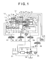
- FIG 1 is a partially sectioned side view showing a construction of an injection molding machine in accordance with a first embodiment of the present invention and a block diagram showing a control system for the injection molding machine
- FIG. 2 is a diagram showing pressure-flow rate characteristics of control using a pressure compensator of a variable discharge pump provided in an oil pressure control system for the injection molding machine shown in FIG. 1
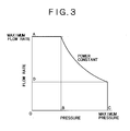
- FIG. 3 is a diagram showing pressure-flow rate characteristics of power constant control using a variable discharge pump.
- An injection molding machine 10 shown in FIG. 1 mainly includes a fixed die plate 2 provided fixedly on a base 1, a fixed die 4 installed on the fixed die plate 2, a movable die plate 3 provided movably on the base 1 so as to face the fixed die plate 2, a movable die 5 installed on the movable die plate 3, tie bars 31 each inserted in an insertion hole 3b of the movable die plate 3 to connect the movable die plate 3 to the fixed die plate 2 at the time of die clamping, split nuts 33 each engaging with a plurality of ring grooves formed at equal intervals in the tie bar 31 to fix the tie bar 31 on the outside of the movable die plate 3, a unit transfer bed 41 provided movably on the base 1, an injection cylinder bed 37 integral with an injection cylinder 6 provided fixedly on the unit transfer bed 41, a screw driving motor bed 42 rotatably supporting an injection screw 7 while restraining it in the axial direction and movable on the unit transfer bed 41, and an injection screw driving servomotor 9.
- Means for operating such main elements include electric die opening/closing means 11, hydraulic die clamping means 12, hydraulic product ejecting means 13, electric screw driving means 14, and hydraulic injecting means 15.
- a hydraulic power source for supplying pressurized hydraulic oil to a hydraulic actuator a variable discharge pump 54 having the maximum necessary delivery capacity at least for each of hydraulic actuators at the time of the highest rotational speed of pump is used.
- the discharged oil pressure of the pump 54 is controlled by a discharge cutoff function (of the characteristic curve shown in FIG. 2) of an ancillary pressure compensator 55.
- the pump 54 is driven by an AC motor 53, and the rotational speed of the AC motor 53 is controlled by an inverter 52 so that the rotation control can be carried out in a stepless mode.
- the electric die opening/closing means 11 is constructed so that the power of a servomotor 23 turns a ball screw shaft 21, which is supported on bearing beds 24 and 25 provided fixedly on the base 1, via a power transmitting mechanism 26, by which the movable tie plate 3 fitted with a ball screw nut 22 engaging threadedly with the ball screw shaft 21 is moved in the direction of die opening/closing operation.
- the servomotor 23 controls the movable die plate 3 so that the movable die plate 3 is accelerated slowly according to a die clamping transfer speed control program incorporated in a controller 51, and after being moved at a fixed speed, it is decelerated so as to stop just before the movable die 5 comes into contact with the fixed die 4.
- a hydraulic actuator is composed of a hydraulic die clamping cylinder 2a having a short stroke and a large diameter and a large-diameter piston 32 slidingly moving in the cylinder 2a.
- the die clamping cylinder 2a is provided in plural number (four in this embodiment) in the fixed die plate 2.
- the piston 32 is connected integrally with the tie bar 31. After the split nut 33 engages with the ring grooves formed at equal intervals in the tie bar 31, and thus the tie bar 31 is fixed on the outside of the movable die plate 3, a four-way switching valve 56 is switched.
- hydraulic oil is fed to the left-hand side in the figure of the die clamping cylinder 2a, by which the dies 4 and 5 are clamped.
- every port of the four-way switching valve 56 is closed to maintain the die clamping oil pressure in the die clamping cylinder 2a.
- a two-way switching valve 57 is opened at the same time that the four-way switching valve 56 is switched, and thus the same oil pressure acts on both sides of the piston 32, so that a die releasing force is created on the piston 32 by a difference in oil pressure actuating area (the oil pressure actuating area on the left-hand side of the piston 32 is smaller by the area of tie bar 31).
- the hydraulic product ejecting means 13 is made up of a hydraulic cylinder 34, a piston 35, an eject bar 36, and the like.
- the hydraulic oil discharged from the variable discharge pump 54 is switched by a four-way switching valve 61 to operate the eject bar 36, by which a product is projected and taken out of the movable die 5.
- the electric screw driving means 14 has the screw driving motor bed 42 rotatably supporting the injection screw 7 while restraining it in the axial direction.
- the screw driving motor bed 42 is mounted with the servomotor 9 directly connected to the injection screw 7 , and via the servomotor 9 driven in accordance with an injection screw rotational speed control program incorporated in the controller 51, the rotational speed of the injection screw 7 is controlled.
- the screw 7 turns and molten resin is plasticized, the molten resin accumulates at the tip end of the injection screw 7.
- the back pressure during the plasticization is controlled by a proportional pressure valve 59.
- the hydraulic injecting means 15 has the injection cylinder bed 37 integral with the injection cylinder 6, and the injection cylinder bed 37 is provided with a pair of hydraulic cylinders 37a and hydraulic pistons 38 disposed in parallel symmetrically with respect to the central axis of the injection cylinder 6.
- the hydraulic injecting means 15 is constructed so that the hydraulic oil discharged from the variable discharge pump 54 is switched by a four-way switching valve 58 according to an injection screw advance/retreat speed control program incorporated in the controller 51, and thus the rotational speed of the variable discharge pump 54 is regulated, by which the advance speed of the injection screw 7 is controlled.
- Hydraulic nozzle touching means 16 is constructed so that by switching a four-way switching valve 62 from a state in which a nozzle of the injection cylinder 6 is separated from the fixed die plate 2, the hydraulic oil delivered from the variable discharge pump 54 is sent to a right-hand chamber of a hydraulic cylinder 43 in FIG. 1, a piston 44 is moved in the left direction, and a rod 45 draws the injection cylinder bed 37 to the left-hand side, by which the nozzle of the injection cylinder 6 is touched to the fixed die plate 2.
- the nozzle of the injection cylinder 6 is touched to the fixed die plate 2 by the nozzle touching means 16, and the oil pressure in the right-hand chamber of the hydraulic cylinder 43 is held in preparation for the injection process, by which work is started from a completely opened die state in which the movable die plate 3 lies at the retreat end.
- the four-way switching valve 56 first opens a hydraulic oil supply pipe to the die clamping cylinder 2a, and the variable discharge pump 54 is started with the oil pressure and flow rate programmed in the controller 51 by a command of the controller 51 (at this time, the oil pressure is set at a die clamping pressure set value).
- the hydraulic oil is sent into a left-hand chamber of the die clamping cylinder 2a in FIG. 1, the piston 32 moves to decrease a narrow gap between the dies 4 and 5, so that the dies 4 and 5 come into contact with each other, and thus the hydraulic oil is compressed, by which the pressure is increased.
- the pressure compensator 55 acts on a discharge change mechanism (slant plate) of the variable discharge pump 54 while the oil pressure is maintained to carry out the cutoff control of flow rate. After the cutoff control, pressure oil of only a leak from the die clamping cylinder 2a has only to be supplied, so that the rotational speed of the variable discharge pump 54 is decreased to reduce electric power consumption and noise.
- the hydraulic injecting means 15 is operated to inject molten resin accumulating at the tip end of the injection screw 7 of the injection cylinder 6 into a cavity of the dies 4 and 5.
- the molten resin in the die cavity is cooled and solidified in a pressure holding state to form a product.
- the variable discharge pump 54 is in a stopped state while the oil pressure is held.
- the process proceeds to die releasing of the dies 4 and 5.
- the four-way switching valve 56 is switched to the same switching position as that in the above-described die clamping process, and the two-way switching valve 57 is opened, by which the variable discharge pump 54 is operated with the flow rate programmed in the controller 51.
- the set oil pressure is applied to oil chambers on both sides of the piston 32 in the die clamping cylinder 2a, and the piston 32 is subjected to a force in the die releasing direction by a difference in oil pressure actuating area between the both sides of the piston 32, by which the fixed die 4 and the movable die 5 are released from each other.
- the hydraulic oil scarcely flows to the outside.
- the locking means such as the split nuts 33 are operated reversely to lift the restraint of the tie bars 31 with respect to the movable die plate 3, and thus the movable die plate 3 is moved by the electric opening/closing means 11, by which the fixed die 4 and the movable die 5 are opened.
- the product ejecting means 13 is operated hydraulically to project the eject bar 36, by which a product is taken out of the movable die 5. After the product is taken out, the next die closing operation starts.
- the hydraulic injection nozzle touching means 16 is operated reversely.
- variable discharge pump 54 is matched with the oil pressure and flow rate necessary for each of the processes, and the running hours and timing are set by programming in advance. By doing this, the hydraulic operation control of the injection molding machine 10 can be carried out only by direct program control of the variable discharge pump 54. Also, the flow rate of high pressure holding at the end of cylinder etc. can be cut off by the pressure compensator 55. Therefore, the relief valve is unnecessary, and energy loss in the hydraulic operation flow rate can be reduced. If the rotational speed of the variable discharge pump 54 is decreased during the high pressure holding, energy loss and pump noise can further be reduced.
- the AC motor 53 When it is desired to use the capacity of the variable discharge pump 54 fully as in the case of the hydraulic die clamping means 12 and the hydraulic injecting means 15, the AC motor 53 is rotated at a high speed and the variable discharge pump 54 is driven at the usable limit output, and program control is carried out so that the pressure and flow rate along the power constant characteristic curve shown in FIG. 3 are obtained. By doing this, an excessive load is not imposed on the AC motor 53 and the variable discharge pump 54, and the highest operation efficiency can be obtained. Also, since the die releasing operation uses a low pressure and the highest flow rate, and the die clamp holding operation uses a high pressure and a low flow rate as in the range of A and C in FIG. 3, if the power is constant, a motor with a power lower than the power of highest pressure x highest flow rate can be selected.
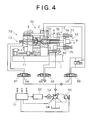
- FIG 4 is a partially sectioned side view showing a construction of an injection molding machine in accordance with a second embodiment of the present invention and a block diagram showing a control system for the injection molding machine.
- An injection molding machine 70 of the second embodiment uses electric injecting means 17 in place of the hydraulic injecting means 15 of the injection molding machine 10 in the first embodiment.
- the construction of the injection molding machine 70 is the same as that of the injection molding machine 10 shown in FIG. 1, so that the explanation of the construction and function of common portions is omitted. Since the injection molding machine 70 is not provided with the hydraulic injecting means 15, the four-way switching valve 58 is unnecessary.
- the electric injecting means 17 has a pair of ball screw shafts 73 disposed symmetrically on both sides of the injection cylinder 6, and the paired ball screw shafts 73 are rotatably supported on an injection cylinder bed 76 while being restrained in the axial direction. Also, in the electric injecting means 17, a ball screw nut 74 engaging threadedly with the ball screw shaft 73 is installed to a screw driving motor bed 75, and the injection speed of the injection screw 7 is controlled by a controller 71 via a pair of servomotors 72 rotating synchronously that are installed on the injection cylinder bed 76.
- variable discharge pump 54 In an actuating process to which the variable discharge pump 54 relates, since there is no hydraulic injecting means, a portion in which the timing of process overlaps is eliminated, so that it is necessary only that the variable discharge pump 54 be program controlled so that pressure and flow rate that are suited to the drive of each actuator are delivered.
Landscapes
- Engineering & Computer Science (AREA)
- Manufacturing & Machinery (AREA)
- Mechanical Engineering (AREA)
- Injection Moulding Of Plastics Or The Like (AREA)
- Fluid-Pressure Circuits (AREA)
Abstract
Description
Claims (8)
- A hydraulic actuating mechanism of an injection molding machine, in which a plurality of hydraulic actuators are driven by one hydraulic pump, wherein the hydraulic pump of said hydraulic actuating mechanism is a variable discharge pump having the maximum necessary delivery capacity at least for each of said hydraulic actuators at the time of the highest rotational speed of said pump; the discharged fluid pressure is controlled by a discharge cutoff function of a pressure compensator ancillary to said variable discharge pump; and said pump is driven by a motor whose rotation can be controlled in a stepless mode.
- The hydraulic actuating mechanism of an injectionmolding machine according to claim 1, wherein the motor capable of controlling the rotation of said variable discharge pump in a stepless mode is an inverter controlled motor or an AC servomotor.
- A control method for the hydraulic actuating mechanism according to claim 1 or 2, wherein the maximum load (flow rate x pressure) of said hydraulic actuator is controlled so as to match with a characteristic diagram in which flow rate x pressure of said variable discharge pump is constant.
- A control method for the hydraulic actuating mechanism according to claim 1 or 2, wherein the fluid pressure cutoff control of said variable discharge pump is program control for operating a fluid pressure cutoff mechanism of said variable discharge pump by using a proportional pressure valve.
- An injection molding machine in which two or more of driving means including injection nozzle touching means, die clamping means, die opening/closing means, screw driving means, injecting means, and product ejecting means are driven hydraulically by using the hydraulic actuating mechanism according to claim 1 or 2, and other driving means are driven electrically.
- The injection molding machine according to claim 5, wherein said die opening/closing means, injectingmeans, and screw driving means are driven electrically.
- A control method for the injection molding machine according to claim 5 or 6, wherein the maximum load (flow rate x pressure) of said hydraulic actuator is controlled so as to match with a characteristic diagram in which flow rate x pressure of said variable discharge pump is constant.
- A control method for the injection molding machine according to claim 5 or 6, wherein the fluid pressure cutoff control of said variable discharge pump is program control for operating a fluid pressure cutoff mechanism of said variable discharge pump by using a proportional pressure valve.
Applications Claiming Priority (2)
| Application Number | Priority Date | Filing Date | Title |
|---|---|---|---|
| JP2001260696A JP3799366B2 (en) | 2001-08-30 | 2001-08-30 | Injection molding machine and control method thereof |
| JP2001260696 | 2001-08-30 |
Publications (3)
| Publication Number | Publication Date |
|---|---|
| EP1287968A2 true EP1287968A2 (en) | 2003-03-05 |
| EP1287968A3 EP1287968A3 (en) | 2003-08-06 |
| EP1287968B1 EP1287968B1 (en) | 2006-04-19 |
Family
ID=19087858
Family Applications (1)
| Application Number | Title | Priority Date | Filing Date |
|---|---|---|---|
| EP02014945A Expired - Lifetime EP1287968B1 (en) | 2001-08-30 | 2002-07-08 | Injection molding machine comprising a hydraulic actuating mechanism and control method therefor |
Country Status (7)
| Country | Link |
|---|---|
| US (1) | US6878317B2 (en) |
| EP (1) | EP1287968B1 (en) |
| JP (1) | JP3799366B2 (en) |
| CN (1) | CN1201917C (en) |
| CA (1) | CA2384392C (en) |
| DE (1) | DE60210714T2 (en) |
| TW (1) | TW517000B (en) |
Cited By (4)
| Publication number | Priority date | Publication date | Assignee | Title |
|---|---|---|---|---|
| WO2006005638A1 (en) * | 2004-07-09 | 2006-01-19 | Demag Ergotech Gmbh | Injection moulding machine |
| US7938994B2 (en) * | 2005-09-08 | 2011-05-10 | Nissei Plastic Industrial Co., Ltd. | Method of controlling an injection molding machine |
| WO2012051560A1 (en) * | 2010-10-15 | 2012-04-19 | Eaton Corporation | Hybrid hydraulic systems for industrial processes |
| US9346207B2 (en) | 2010-10-18 | 2016-05-24 | Eaton Corporation | Hydraulic drive circuit with parallel architectured accumulator |
Families Citing this family (31)
| Publication number | Priority date | Publication date | Assignee | Title |
|---|---|---|---|---|
| JP2004050814A (en) * | 2002-05-28 | 2004-02-19 | Toshiba Mach Co Ltd | Hybrid power supply type injection molding machine system |
| US7168944B2 (en) * | 2002-12-10 | 2007-01-30 | Husky Injection Molding Systems Ltd. | Energy efficient extruder drive |
| JP4355309B2 (en) * | 2005-09-08 | 2009-10-28 | 日精樹脂工業株式会社 | Injection molding machine |
| JP4324148B2 (en) * | 2005-09-08 | 2009-09-02 | 日精樹脂工業株式会社 | Injection molding machine and control method thereof |
| US8078327B2 (en) * | 2006-04-04 | 2011-12-13 | Union Plastic (Hangzhou) Machinery Co., Ltd. | Control method of a hydraulic machine for saving energy or improving efficiency |
| US20080089964A1 (en) * | 2006-10-13 | 2008-04-17 | Husky Injection Molding Systems Ltd. | Drive of molding system |
| JP4548488B2 (en) | 2008-01-22 | 2010-09-22 | ダイキン工業株式会社 | Merge control system |
| JP5147120B2 (en) * | 2008-04-21 | 2013-02-20 | 株式会社名機製作所 | Injection molding machine |
| JP4805975B2 (en) * | 2008-05-29 | 2011-11-02 | 日精樹脂工業株式会社 | Control method of injection molding machine |
| BRPI0920538A2 (en) * | 2008-10-03 | 2015-12-29 | Athena Automation Ltd | movable plate displacement actuator injection molding machine |
| JP5330945B2 (en) * | 2008-10-29 | 2013-10-30 | 三菱重工業株式会社 | Hydraulic system and wind power generator equipped with the same |
| JP5604615B2 (en) * | 2009-03-23 | 2014-10-08 | 佐藤 寛 | Energy saving control device and equipment or injection molding machine equipped with this energy saving control device |
| DE102010001595B4 (en) * | 2010-02-04 | 2012-05-16 | Sumitomo (Shi) Demag Plastics Machinery Gmbh | Injection molding machine and hydraulic drive unit for this |
| JP5363431B2 (en) * | 2010-08-03 | 2013-12-11 | 日精樹脂工業株式会社 | Vertical injection molding equipment |
| CN102452153A (en) * | 2010-10-25 | 2012-05-16 | 鸿富锦精密工业(深圳)有限公司 | Mold ejection device and injection molding equipment |
| JP5495388B2 (en) * | 2010-11-03 | 2014-05-21 | 株式会社名機製作所 | Injection molding machine and control method of injection molding machine |
| US9902101B2 (en) * | 2012-01-26 | 2018-02-27 | Husky Injection Molding Systems Ltd. | Screw-moving assembly including screw-moving actuator and bias-adjustment mechanism |
| JP5509256B2 (en) * | 2012-05-16 | 2014-06-04 | 日精樹脂工業株式会社 | Injection molding equipment |
| JP5782012B2 (en) * | 2012-11-14 | 2015-09-24 | 日精樹脂工業株式会社 | Liquid resin molding equipment |
| DE102012111300A1 (en) | 2012-11-22 | 2014-05-22 | Linde Hydraulics Gmbh & Co. Kg | Hydrostatic engine as a hydraulic starter of an internal combustion engine |
| JP6005176B2 (en) * | 2012-11-27 | 2016-10-12 | 日立建機株式会社 | Hydraulic drive device for electric hydraulic work machine |
| JP5755261B2 (en) * | 2013-01-24 | 2015-07-29 | 株式会社名機製作所 | Injection molding machine and injection molding method |
| BE1021675B1 (en) * | 2013-04-26 | 2016-01-05 | Gb Boucherie Nv | INJECTION MOLDING |
| JP6198596B2 (en) * | 2013-12-11 | 2017-09-20 | 株式会社松井製作所 | Medium supply device |
| JP6367079B2 (en) * | 2014-10-22 | 2018-08-01 | 住友重機械工業株式会社 | Injection molding machine |
| US10239246B2 (en) | 2015-03-03 | 2019-03-26 | Limworks, Llc | Injection molding machine |
| EP4272924A3 (en) | 2019-10-04 | 2024-01-24 | Husky Injection Molding Systems Luxembourg IP Development S.à.r.l | Stabilized adaptive hydraulic system pressure in an injection molding system |
| AT523856B1 (en) * | 2020-06-05 | 2022-03-15 | Engel Austria Gmbh | Forming machine with a closed hydraulic drive system |
| CN111720375B (en) * | 2020-07-30 | 2026-05-01 | 宁波埃科思注塑科技有限公司 | Precision closed oil circuit oil-electricity composite injection molding machine |
| JP7837669B2 (en) * | 2020-10-13 | 2026-03-31 | 株式会社日本製鋼所 | Injection device and injection molding machine |
| AT527222B1 (en) * | 2023-12-14 | 2024-12-15 | Engel Austria Gmbh | production facility |
Family Cites Families (9)
| Publication number | Priority date | Publication date | Assignee | Title |
|---|---|---|---|---|
| JPS60176737A (en) * | 1984-02-23 | 1985-09-10 | Mitsubishi Heavy Ind Ltd | Power match type accumulator circuit |
| US5052909A (en) | 1990-01-19 | 1991-10-01 | Cincinnati Milacron Inc. | Energy-conserving injection molding machine |
| US5634334A (en) | 1992-10-14 | 1997-06-03 | Hehl; Karl | Hydraulic device for use in a production machine |
| DE4335403C1 (en) * | 1993-10-18 | 1994-12-15 | Karl Hehl | Hydraulic device |
| DE4335328A1 (en) | 1993-10-18 | 1995-04-20 | Battenfeld Gmbh | Hydraulic operating system for injection molding machines |
| AT400941B (en) | 1994-03-22 | 1996-04-25 | Engel Gmbh Maschbau | DEVICE FOR SUPPLYING HYDRAULIC CONSUMERS OF AN INJECTION MOLDING MACHINE WITH A PRESSURIZED HYDRAULIC LIQUID |
| JP4021479B2 (en) * | 1995-05-16 | 2007-12-12 | グローブマグ・リミテッド・パートナーシップ | Device with at least one hydraulic shaft |
| JP2000052392A (en) * | 1998-08-11 | 2000-02-22 | Toshiba Mach Co Ltd | Hydraulic pressure control circuit for injection molding machine |
| US6478572B1 (en) * | 2000-07-06 | 2002-11-12 | Husky Injection Molding Systems, Ltd. | Energy efficient extruder drive |
-
2001
- 2001-08-30 JP JP2001260696A patent/JP3799366B2/en not_active Expired - Fee Related
-
2002
- 2002-04-26 TW TW091108755A patent/TW517000B/en not_active IP Right Cessation
- 2002-04-27 CN CN02122182.0A patent/CN1201917C/en not_active Expired - Fee Related
- 2002-05-01 CA CA002384392A patent/CA2384392C/en not_active Expired - Fee Related
- 2002-05-02 US US10/136,523 patent/US6878317B2/en not_active Expired - Fee Related
- 2002-07-08 EP EP02014945A patent/EP1287968B1/en not_active Expired - Lifetime
- 2002-07-08 DE DE60210714T patent/DE60210714T2/en not_active Expired - Lifetime
Cited By (9)
| Publication number | Priority date | Publication date | Assignee | Title |
|---|---|---|---|---|
| WO2006005638A1 (en) * | 2004-07-09 | 2006-01-19 | Demag Ergotech Gmbh | Injection moulding machine |
| DE102004033690A1 (en) * | 2004-07-09 | 2006-02-16 | Demag Ergotech Gmbh | Injection molding machine |
| US7938994B2 (en) * | 2005-09-08 | 2011-05-10 | Nissei Plastic Industrial Co., Ltd. | Method of controlling an injection molding machine |
| WO2012051560A1 (en) * | 2010-10-15 | 2012-04-19 | Eaton Corporation | Hybrid hydraulic systems for industrial processes |
| CN103249950A (en) * | 2010-10-15 | 2013-08-14 | 伊顿公司 | Hybrid hydraulic systems for industrial processes |
| US8991167B2 (en) | 2010-10-15 | 2015-03-31 | Eaton Corporation | Hybrid hydraulic systems for industrial processes |
| CN103249950B (en) * | 2010-10-15 | 2015-07-22 | 伊顿公司 | Hybrid hydraulic systems for industrial processes |
| US9874233B2 (en) | 2010-10-15 | 2018-01-23 | Eaton Corporation | Hybrid hydraulic systems for industrial processes |
| US9346207B2 (en) | 2010-10-18 | 2016-05-24 | Eaton Corporation | Hydraulic drive circuit with parallel architectured accumulator |
Also Published As
| Publication number | Publication date |
|---|---|
| JP2003074505A (en) | 2003-03-12 |
| CN1403267A (en) | 2003-03-19 |
| US6878317B2 (en) | 2005-04-12 |
| EP1287968B1 (en) | 2006-04-19 |
| DE60210714D1 (en) | 2006-05-24 |
| CA2384392C (en) | 2006-07-11 |
| CN1201917C (en) | 2005-05-18 |
| DE60210714T2 (en) | 2007-01-04 |
| TW517000B (en) | 2003-01-11 |
| EP1287968A3 (en) | 2003-08-06 |
| US20030042640A1 (en) | 2003-03-06 |
| JP3799366B2 (en) | 2006-07-19 |
| CA2384392A1 (en) | 2003-02-28 |
Similar Documents
| Publication | Publication Date | Title |
|---|---|---|
| EP1287968B1 (en) | Injection molding machine comprising a hydraulic actuating mechanism and control method therefor | |
| US5052909A (en) | Energy-conserving injection molding machine | |
| JP4408134B2 (en) | Hydraulic supply device, injection molding machine, and control method of hydraulic actuator device using the same | |
| EP3381645B1 (en) | Injection molding machine | |
| CN103568236B (en) | Hydraulic source control device and injection molding device | |
| CN103921418B (en) | Injection molding machine | |
| CN119159762A (en) | Hydraulic system and injection molding machine | |
| CN102639881A (en) | Kinematic control in a hydraulic system | |
| CN1980783A (en) | Injection moulding machine | |
| JP5921736B2 (en) | Injection molding machine and control method of injection molding machine | |
| CN119116302A (en) | Hydraulic system and injection molding machine | |
| US7004224B2 (en) | Diecasting machine | |
| JP4167842B2 (en) | Hydraulic control method and control apparatus for injection molding machine | |
| JP5495388B2 (en) | Injection molding machine and control method of injection molding machine | |
| JP4048671B2 (en) | Method for controlling mold clamping device and pressurizing mechanism | |
| JP7006316B2 (en) | Extrusion press and control method of extrusion press | |
| CN104708786B (en) | Forming device and method for controlling the forming device | |
| JP2006256179A (en) | Mold opening and closing method of injection molding machine and mold opening and closing device | |
| JP3782068B2 (en) | Clamping device for vertical injection molding machine | |
| JP4646695B2 (en) | Die casting machine | |
| JPH0796541A (en) | Energy - saving injection molding machine | |
| JPS63212524A (en) | Clamping device for injection molding machine | |
| JP7796172B1 (en) | Drive control device and drive control method for hydraulic injection molding machine | |
| JP7648447B2 (en) | Injection Unit and Molding Machine | |
| JP7137729B1 (en) | Local pressure device and molding machine |
Legal Events
| Date | Code | Title | Description |
|---|---|---|---|
| PUAI | Public reference made under article 153(3) epc to a published international application that has entered the european phase |
Free format text: ORIGINAL CODE: 0009012 |
|
| 17P | Request for examination filed |
Effective date: 20020708 |
|
| AK | Designated contracting states |
Kind code of ref document: A2 Designated state(s): AT BE BG CH CY CZ DE DK EE ES FI FR GB GR IE IT LI LU MC NL PT SE SK TR |
|
| AX | Request for extension of the european patent |
Extension state: AL LT LV MK RO SI |
|
| PUAL | Search report despatched |
Free format text: ORIGINAL CODE: 0009013 |
|
| AK | Designated contracting states |
Designated state(s): AT BE BG CH CY CZ DE DK EE ES FI FR GB GR IE IT LI LU MC NL PT SE SK TR |
|
| AX | Request for extension of the european patent |
Extension state: AL LT LV MK RO SI |
|
| AKX | Designation fees paid |
Designated state(s): DE IT |
|
| 17Q | First examination report despatched |
Effective date: 20050510 |
|
| GRAP | Despatch of communication of intention to grant a patent |
Free format text: ORIGINAL CODE: EPIDOSNIGR1 |
|
| RTI1 | Title (correction) |
Free format text: INJECTION MOLDING MACHINE COMPRISING A HYDRAULIC ACTUATING MECHANISM AND CONTROL METHOD THEREFOR |
|
| GRAS | Grant fee paid |
Free format text: ORIGINAL CODE: EPIDOSNIGR3 |
|
| GRAA | (expected) grant |
Free format text: ORIGINAL CODE: 0009210 |
|
| AK | Designated contracting states |
Kind code of ref document: B1 Designated state(s): DE IT |
|
| REF | Corresponds to: |
Ref document number: 60210714 Country of ref document: DE Date of ref document: 20060524 Kind code of ref document: P |
|
| PLBE | No opposition filed within time limit |
Free format text: ORIGINAL CODE: 0009261 |
|
| STAA | Information on the status of an ep patent application or granted ep patent |
Free format text: STATUS: NO OPPOSITION FILED WITHIN TIME LIMIT |
|
| 26N | No opposition filed |
Effective date: 20070122 |
|
| PGFP | Annual fee paid to national office [announced via postgrant information from national office to epo] |
Ref country code: IT Payment date: 20140715 Year of fee payment: 13 |
|
| PG25 | Lapsed in a contracting state [announced via postgrant information from national office to epo] |
Ref country code: IT Free format text: LAPSE BECAUSE OF NON-PAYMENT OF DUE FEES Effective date: 20150708 |
|
| PGFP | Annual fee paid to national office [announced via postgrant information from national office to epo] |
Ref country code: DE Payment date: 20170705 Year of fee payment: 16 |
|
| REG | Reference to a national code |
Ref country code: DE Ref legal event code: R119 Ref document number: 60210714 Country of ref document: DE |
|
| PG25 | Lapsed in a contracting state [announced via postgrant information from national office to epo] |
Ref country code: DE Free format text: LAPSE BECAUSE OF NON-PAYMENT OF DUE FEES Effective date: 20190201 |