EP1287715B1 - Systeme de liaison radioelectrique en milieu confine entre terminaux de telephonie mobile - Google Patents
Systeme de liaison radioelectrique en milieu confine entre terminaux de telephonie mobile Download PDFInfo
- Publication number
- EP1287715B1 EP1287715B1 EP01940620A EP01940620A EP1287715B1 EP 1287715 B1 EP1287715 B1 EP 1287715B1 EP 01940620 A EP01940620 A EP 01940620A EP 01940620 A EP01940620 A EP 01940620A EP 1287715 B1 EP1287715 B1 EP 1287715B1
- Authority
- EP
- European Patent Office
- Prior art keywords
- terminal
- mobile telephony
- telephony terminal
- individual portable
- portable module
- Prior art date
- Legal status (The legal status is an assumption and is not a legal conclusion. Google has not performed a legal analysis and makes no representation as to the accuracy of the status listed.)
- Expired - Lifetime
Links
- 230000001413 cellular effect Effects 0.000 claims abstract description 7
- 238000003199 nucleic acid amplification method Methods 0.000 claims abstract description 5
- 230000005540 biological transmission Effects 0.000 claims description 21
- 238000004891 communication Methods 0.000 claims description 14
- 230000017105 transposition Effects 0.000 claims description 8
- 230000005855 radiation Effects 0.000 claims description 6
- 230000001174 ascending effect Effects 0.000 claims description 2
- 238000012360 testing method Methods 0.000 description 6
- 238000011144 upstream manufacturing Methods 0.000 description 4
- 238000009434 installation Methods 0.000 description 3
- 239000000470 constituent Substances 0.000 description 2
- 238000012423 maintenance Methods 0.000 description 2
- 230000003321 amplification Effects 0.000 description 1
- 238000013459 approach Methods 0.000 description 1
- 230000015556 catabolic process Effects 0.000 description 1
- 238000012512 characterization method Methods 0.000 description 1
- 230000000052 comparative effect Effects 0.000 description 1
- 238000010276 construction Methods 0.000 description 1
- 230000006378 damage Effects 0.000 description 1
- 230000007812 deficiency Effects 0.000 description 1
- 230000009365 direct transmission Effects 0.000 description 1
- 238000005516 engineering process Methods 0.000 description 1
- 231100001261 hazardous Toxicity 0.000 description 1
- 238000000034 method Methods 0.000 description 1
- 238000004804 winding Methods 0.000 description 1
Images

Classifications
-
- H—ELECTRICITY
- H04—ELECTRIC COMMUNICATION TECHNIQUE
- H04W—WIRELESS COMMUNICATION NETWORKS
- H04W88/00—Devices specially adapted for wireless communication networks, e.g. terminals, base stations or access point devices
- H04W88/02—Terminal devices
-
- H—ELECTRICITY
- H04—ELECTRIC COMMUNICATION TECHNIQUE
- H04B—TRANSMISSION
- H04B7/00—Radio transmission systems, i.e. using radiation field
- H04B7/24—Radio transmission systems, i.e. using radiation field for communication between two or more posts
- H04B7/26—Radio transmission systems, i.e. using radiation field for communication between two or more posts at least one of which is mobile
- H04B7/2603—Arrangements for wireless physical layer control
- H04B7/2606—Arrangements for base station coverage control, e.g. by using relays in tunnels
-
- H—ELECTRICITY
- H04—ELECTRIC COMMUNICATION TECHNIQUE
- H04W—WIRELESS COMMUNICATION NETWORKS
- H04W16/00—Network planning, e.g. coverage or traffic planning tools; Network deployment, e.g. resource partitioning or cells structures
- H04W16/24—Cell structures
- H04W16/26—Cell enhancers or enhancement, e.g. for tunnels, building shadow
Definitions
- the invention relates to a radio transmission system in a confined environment between mobile telephone terminals.
- the range of mobile telephone terminals, operating in the 80-160 MHz frequency bands, remains very limited in a confined environment, particularly in road or rail tunnels, mine tunnels, which are long, deep and winding by nature.
- the above-mentioned mine galleries may be equipped with specific installations, consisting of radiating cables and relay amplifiers, making it possible to provide a suitable radio link between each mobile telephone terminal and a fixed cellular telephone terminal placed at the same time. outside the corresponding confined area. The radio link between mobile radio terminals placed inside the confined zone is then necessarily carried out via the aforementioned specific installations and the corresponding fixed cellular telephone terminal.
- the present invention relates to the implementation of a radio transmission system in a confined environment, between mobile telephone terminals, presenting all the features of mobile radio telephony.
- Another object of the present invention is also, in addition to the implementation of the aforementioned functionalities, the maintenance of radio links from mobile terminal to portable radio terminal, within a restricted perimeter of the confined medium, by a single frequency simplex link.
- the radio transmission system in confined space between at least one mobile telephone terminal, transmitting and receiving a high frequency radio signal, and a fixed mobile telephone terminal, object of the present invention is remarkable in that it comprises in combination, an individual portable module connected to this mobile telephone terminal and comprising a microwave transponder, this individual portable module receiving the radio frequency signal emitted by the mobile terminal and retransmitting, in the confined medium, a radio signal microwave, at least one transportable relay station providing a re-amplification of the microwave radio signal and a retransmission, to a free aperture of the confined medium, an amplified microwave signal, a terminal station provided with a transponder placed in the vicinity of this free opening.
- the confined radio transmission system finds application during the intervention of authorized personnel or security in hazardous conditions, in confined environments such as tunnels, railways or road mines galleries or the like .
- Fixed cellular telephony referred to as a fixed relay, external to the aforementioned confined medium, comprises, in accordance with the subject of the present invention, in combination, an individual portable module 1 connected to this mobile telephone terminal.
- an individual portable module 1 connected to each of the mobile telephone terminals T 1 and T 2 for purely illustrative purposes.
- Each individual portable module 1 comprises a microwave transponder.
- Each individual portable module 1 receives the high frequency radio signal, 80 or 160 MHz RF signal transmitted by the mobile telephone terminal T 1 , respectively T 2 , and retransmits in the confined medium a microwave radio signal in the SHF band between 2 and 3 GHz.
- the system which is the subject of the present invention comprises at least one transportable relay station, bearing the reference 2, ensuring a re-amplification of the microwave radio frequency signal, that is to say of the signal emitted in the SHF band, and a retransmission to a free opening of the confined medium, free opening denoted by OL, of an amplified microwave radio frequency signal.
- the radio transmission system in confined space, object of the present invention is shown installed in a tunnel, denoted TU, such as a road or rail tunnel for example, whose free opening OL corresponds to the entrance of the tunnel, while the length of the tunnel is large enough to consider the latter as closed at the other end.
- TU such as a road or rail tunnel for example
- a terminal station denoted 3, provided with a transponder is placed in the vicinity of the aforementioned OL free opening, this terminal station 3 ensuring the reception of the amplified hyperfrequency radio signal, the transposition of this amplified microwave signal into a signal transposed at high frequency in the 80 - 160 MHz band and the transmission of this signal transposed in an unconfined environment to the fixed mobile telephony terminal, referred to as a fixed relay.
- the radio link system as described above makes it possible to ensure the connection of any mobile telephone terminal, such as T 1 or T 2 , with the fixed relay constituting the fixed mobile telephony terminal previously mentioned.
- the implementation mode of the radio transmission system in a confined object object of the present invention is not limited to a mode of implementation of simplex type in the alternate, in which an upward channel, the if necessary downward, is simply installed.
- each individual portable module 1, the transportable relay station 2 and terminal station 3 allow their operations to be combination according to an upstream transmission path, that is to say to the fixed relay, respectively in a downlink transmission channel, that is to say the fixed relay to the terminals T 1 and T 2 of mobile telephony placed in a confined atmosphere.
- the upward channel may be implemented from each mobile telephone terminal T 1 and / or T 2 with which the individual portable module 1 is associated, with the upstream transmission channel being allocated a frequency F 11 between the transportable relay station 2 and each individual portable module 1, a frequency F 21 between the transportable relay station 2 and the terminal station 3 for example, and a high frequency frequency F 31 between the intermediate station 3 and the aforementioned fixed relay terminal.
- a frequency F 32 is allocated between the relay constituting the fixed cellular telephone terminal, between the latter and the terminal station 3, a frequency SHF F 22 between the terminal station 3 and the transportable relay station 2, a frequency F 12 between the transportable relay station 2 and each of the individual portable modules 1 associated with each of the mobile telephone terminals T 1 and T 2 .
- communication modes such as the two-way communication mode for example, or if necessary the full duplex communication mode, can be allocated under these conditions by means of the uplink and the downlink.
- Frequency transpositions can be performed by frequency change from a single local oscillator frequency.
- the SHF frequencies allocated to the uplink and to the downlink differ from the same value as the corresponding RF frequencies.
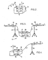
- each individual portable module 1 may comprise, in a sealed housing, one or two transponders bearing the references 12, 13, and represented by an amplifier / mixer providing a change of frequency between the high frequency signal HF and the microwave signal SHF, respectively the microwave signal SHF and the microwave signal HF.
- the aforementioned transponders are connected by means of a coaxial connection cable 10, on the one hand, to the mobile telephone terminal T 1 , respectively T 2 , respectively to an omnidirectional antenna 11 ensuring the transmission and reception of the signal SHF constituent of the upstream transmission channel, respectively of the downstream transmission channel.
- each case can be equipped with an attachment system 14 allowing any party to fix the aforementioned housing, and ultimately the corresponding individual portable module 1, to any part of its equipment adapted for this purpose. Under these conditions, the connection by the coaxial cable 10 to the corresponding mobile telephony terminal T 1 or T 2 then allows each speaker to use the latter in a transparent manner, without taking into account the existence of the aforementioned individual portable module 1.
- each individual portable module can be provided by rechargeable batteries in a manner known per se, which for this reason will not be described in detail.
- this can include, as represented in figure 3 , at least one receiving antenna and one transmitting antenna each constituted by a directional antenna whose main direction of the transmitting / receiving radiation lobe, denoted YY, corresponds substantially to the longitudinal direction of the confined medium.
- each transmitting and / or receiving antenna bearing the reference 21, 22 comprises a main radiation lobe direction, denoted YY, each antenna 21 or 22 being mounted on a tripod 23, 24 via a orientation ball 25, 26, which allows to orient each antenna, and in particular the main direction of the radiation lobe thereof, substantially in the longitudinal direction of the medium confined, in order to ensure propagation conditions as close as possible to the guided propagation conditions for the SHF signal, respectively the amplified SHF signal.
- Each antenna is connected by a coaxial cable type connection wire to a sealed housing 27, which comprises microwave amplifiers, represented by 28 and 29, providing amplification of the signal SHF in the upward or downward direction respectively.
- the housing 27 comprises an autonomous power supply, represented by a battery B constituting an autonomous power supply unit for the relay station 2 thus formed.
- antennas 21 and 22 can be constituted by a set of properly oriented radiating dipoles.
- the terminal station 3 may comprise a directional antenna 30, of the microwave antenna type, whose direction of the transmitting / receiving radiation lobe YY corresponds substantially to the longitudinal direction of the confined medium, the antenna 30 may be similar to the antenna 21 or 22 shown in figure 3 relative to the transportable relay station.
- the antenna 30, mounted on the tripod 31, is connected by a coaxial cable to a sealed housing 32, which comprises a transponder ensuring the transposition of this amplified microwave signal into a high frequency transposed signal for the upward channel, respectively the operation reverse for the descending path, as shown in an illustrative way on the figure 4 .
- Transponders 34 and 35 are connected to the antenna HF 33 and the coaxial cable to the antenna 30.
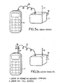
- FIG 5a there is shown a direct connection between the portable individual module 1 and a mobile telephone terminal, such as the terminal T 1 for example.
- the HF antenna of the mobile telephone terminal T 1 has been removed, this type of mobile telephone terminal including an antenna that can be plugged or screwed into a connection socket adapted for this purpose to ensure the transmission of the HF signals transmitted by the mobile terminal T 1 .
- the coaxial cable 10 provided with a connection socket also adapted for this purpose may be connected in place of the above-mentioned HF antenna, thereby ensuring a permanent link between the mobile terminal considered T 1 and the individual portable module 1 associated with the latter.
- each individual portable module 1 may comprise a device for connection to the mobile telephone terminal T 1 specially adapted, so as to enable, on the one hand, the communication of a mobile terminal to a mobile telephone terminal within a restricted area, such as the area of intervention or construction site represented in figure 1 , and, on the other hand, the communication via the individual portable module 1 with the transportable relay station and the terminal station 3.
- FIG. 5b This embodiment is represented in figure 5b in which the HF antenna of the mobile terminal T 1 is not removed, but equipped with an adapter / switch, bearing the reference 15, and providing the connection between the coaxial cable 10 and the above-mentioned HF antenna.
- the adapter / switch 15 can comprise two positions, denoted 1, respectively 2, each switching position that can be selected by the user of the assembly formed by the mobile telephone terminal T 1 , respectively the individual portable module 1 which is associated.
- the mobile terminal T 1 being provided with a simplex communication function vis-à-vis another mobile terminal such as the terminal T 2 shown in FIG. figure 1 for example, this simplex communication function enables the successive exchange of messages on a single frequency between the mobile telephone terminals T 1 and T 2 within the restricted perimeter of the site or intervention perimeter as represented in FIG. figure 1 . It is indicated that this restricted perimeter corresponds to a distance between mobile telephone terminal T 1 and T 2 of the order of approximately 40 meters, when the tunnel is a substantially straight tunnel and for propagation conditions of the HF signal in direct vision of terminal to terminal.
- the coaxial cable 10 is connected to the individual portable module 1 while the free end of this coaxial cable is pluggable into the adapter / switch 15.
- This adapter / switch 15 makes it possible to switch on or position 1 by for example, for a high frequency radio link between the mobile telephone terminal T 1 and the individual portable module 1 associated therewith, or in switch position 2, in the absence of radio frequency link between this mobile terminal T 1 and the individual portable module 1, but in the presence of a simplex communication link vis-à-vis the other terminal T 2 mobile telephony in the aforementioned restricted perimeter.
Landscapes
- Engineering & Computer Science (AREA)
- Computer Networks & Wireless Communication (AREA)
- Signal Processing (AREA)
- Mobile Radio Communication Systems (AREA)
- Radio Relay Systems (AREA)
- Telephone Function (AREA)
- Telephone Set Structure (AREA)
- Pens And Brushes (AREA)
- Radar Systems Or Details Thereof (AREA)
Description
- L'invention concerne un système de liaison radioélectrique en milieu confiné entre terminaux de téléphonie mobile.
- La portée des terminaux de téléphonie mobile, fonctionnant dans les bandes de fréquences 80 - 160 MHz, reste très limitée en milieu confiné, en particulier dans les tunnels routiers ou ferroviaires, les galeries de mine, par nature longs, profonds et sinueux.
- Afin de mieux remédier à un tel inconvénient et de permettre l'utilisation de ces terminaux de téléphonie mobile soit par des utilisateurs habituels tels que passagers de véhicules routiers ou ferroviaires, soit par des personnels de maintenance et d'intervention, les tunnels précités ou le cas échéant les galeries de mine précitées peuvent être équipés d'installations spécifiques, constituées par des câbles rayonnants et des amplificateurs relais, permettant d'assurer une liaison radioélectrique convenable entre chaque terminal de téléphonie mobile et une borne fixe de téléphonie cellulaire, placée à l'extérieur de la zone confinée correspondante. La liaison radioélectrique entre terminaux de radiotéléphonie mobile placés à, l'intérieur de la zone confinée est alors nécessairement effectuée par l'intermédiaire des installations spécifiques précitées et de la borne fixe de téléphonie cellulaire correspondante.
- Toutefois, lors de pannes de ces installations spécifiques ou de très graves sinistres survenant dans ces milieux confinés, la destruction des câbles rayonnants précités sur plusieurs centaines de mètres rend toute liaison entre terminal de téléphonie mobile et l'extérieur et en conséquence avec tout autre terminal de téléphonie mobile situé à l'intérieur du milieu confiné totalement inopérante.
- Une telle carence est en conséquence susceptible de retarder l'intervention de personnels habilités, à l'intérieur du milieu confiné, notamment en cas de sinistre.
- Dans le but de remédier à l'inconvénient majeur précité, différents essais ont été effectués.
- Parmi ceux-ci, la transmission directe en atmosphère confinée à des fréquences radioélectriques comprises entre 1 et 2 GHz s'est révélée envisageable, confer l'article intitulé « Characterization of UHF Radio propagation Channels in Tunnel Environments for microcellular and Personal Communications », publié par Y.P. CHANG and Y. HWANG, IEEE Transactions on Vehicular Technology, vol. 47, N°1, Février 1998.
- Ce résultat a en outre été confirmé par la demande de brevet
DE 3907733 , laquelle décrit un procédé et un dispositif de communication en atmosphère confinée par liaison hyperfréquence en rayonnement polarisé horizontalement ou circulairement. - Alors que les résultats mentionnés dans l'article précité ont montré qu'une liaison directe était envisageable, en raison des conditions de propagation des ondes hyperfréquences en milieu confiné se rapprochant de la propagation guidée, les essais précités n'ont pas été suivis d'une approche industrielle opérationnelle, permettant de bénéficier de la souplesse et de la diversité des fonctionnalités des liaisons de radiotéléphonie mobile.
- La présente invention a pour objet la mise en oeuvre d'un système de liaison radioélectrique en milieu confiné, entre terminaux de téléphonie mobile, présentant toutes les fonctionnalités de la téléphonie radiocellulaire mobile.
- Un autre objet de la présente invention est également, outre la mise en oeuvre des fonctionnalités précitées, le maintien de liaisons radioélectriques de terminal à terminal de radiotéléphonie mobile, dans un périmètre restreint du milieu confiné, par une liaison simplex, à fréquence unique.
- Le système de liaison radioélectrique en milieu confiné entre au moins un terminal de téléphonie mobile, émettant et recevant un signal radioélectrique à haute fréquence', et une borne fixe de téléphonie cellulaire, objet de la présente invention, est remarquable en ce qu'il comporte, en combinaison, un module portatif individuel connecté à ce terminal de téléphonie mobile et comportant un transpondeur hyperfréquence, ce module portatif individuel recevant le signal radioélectrique à haute fréquence émis par le terminal de téléphonie mobile et réémettant, dans le milieu confiné, un signal radioélectrique hyperfréquence, au moins une station relais transportable assurant une réamplification du signal radioélectrique hyperfréquence et une réémission, vers une ouverture libre du milieu confiné, d'un signal hyperfréquence amplifié, une station terminale munie d'un transpondeur placée au voisinage de cette ouverture libre.
- Le système de liaison radioélectrique en milieu confiné, objet de la présente invention, trouve application lors de l'intervention de personnels habilités ou de sécurité dans des conditions périlleuses, dans les milieux confinés tels que tunnels, ferroviaires ou routiers, galeries de mines ou analogues.
- Il sera mieux compris à la lecture de la description et à l'observation des dessins dans lesquels :
- la
figure 1 représente, à titre illustratif, un système de liaison radioélectrique en milieu confiné entre terminal de téléphonie mobile, conforme à l'objet de la présente invention ; - la
figure 2 représente, à titre illustratif, un mode de réalisation particulier non limitatif d'un module portatif individuel permettant la mise en oeuvre du système objet de la présente invention tel que représenté enfigure 1 ; - la
figure 3 représente, à titre illustratif, un mode de réalisation particulier non limitatif d'une station relais transportable, permettant la mise en oeuvre du système objet de la présente invention ; - la
figure 4 représente, à titre illustratif, un mode de réalisation particulier non limitatif d'une station terminale, permettant la mise en oeuvre du système objet de la présente invention ; - la
figure 5a représente, à titre d'exemple non limitatif, un premier mode de réalisation de la connexion du module portatif individuel au terminal de téléphonie mobile ; - la
figure 5b représente, à titre d'exemple non limitatif, un deuxième mode de réalisation préférentiel de la connexion du module portatif individuel au terminal de téléphonie mobile, permettant, au choix de l'utilisateur, soit une liaison de full duplex avec un autre terminal de téléphonie mobile, situé ou non dans le milieu confiné, soit une liaison simplex avec un autre terminal de téléphonie mobile, situé dans le milieu confiné, dans un périmètre restreint de ce terminal de téléphonie mobile. - Une description plus détaillée d'un système de liaison radioélectrique en milieu confiné entre terminaux de téléphonie mobile sera maintenant donnée en liaison avec la
figure 1 et les figures suivantes. - D'une manière générale, ainsi que représenté sur la
figure 1 précitée, le système de liaison radioélectrique en milieu confiné entre au moins un terminal de téléphonie mobile, noté T1, T2, deux terminaux de téléphonie mobile étant représentés sur la figure précitée, émettant et recevant un signal radioélectrique à haute fréquence et une borne fixe de téléphonie cellulaire, notée Relais fixe, externe au milieu confiné précité, comporte, conformément à l'objet de la présente invention, en combinaison, un module 1 portatif individuel connecté à ce terminal de téléphonie mobile. Sur lafigure 1 , à titre d'exemple non limitatif, on a représenté un module portatif individuel 1 connecté à chacun des terminaux de téléphonie mobile T1 et T2 à titre purement illustratif. Chaque module portatif individuel 1 comporte un transpondeur hyperfréquence. Chaque module portatif individuel 1 reçoit le signal radioélectrique à haute fréquence, signal HF à 80 ou 160 MHz émis par le terminal de téléphonie mobile T1, respectivement T2, et réémet dans le milieu confiné un signal radioélectrique hyperfréquence dans la bande SHF comprise entre 2 et 3 GHz. - En outre, le système objet de la présente invention comporte au moins une station relais transportable, portant la référence 2, assurant une réamplification du signal radioélectrique hyperfréquence, c'est-à-dire du signal émis dans la bande SHF, et une réémission vers une ouverture libre du milieu confiné, ouverture libre notée OL, d'un signal radioélectrique hyperfréquence amplifié.
- De manière non limitative et purement illustrative, on indique que, sur la
figure 1 , on a représenté le système de liaison radioélectrique en milieu confiné, objet de la présente invention, installé dans un tunnel, noté TU, tel qu'un tunnel routier ou ferroviaire par exemple, dont l'ouverture libre OL correspond à l'entrée du tunnel, alors que la longueur du tunnel est suffisamment importante pour considérer ce dernier comme fermé à l'autre extrémité. - En outre, une station terminale, notée 3, munie d'un transpondeur est placée au voisinage de l'ouverture libre OL précitée, cette station terminale 3 assurant la réception du signal radioélectrique hyperfréquence amplifié, la transposition de ce signal hyperfréquence amplifié en un signal transposé à haute fréquence dans la bande 80 - 160 MHz et l'émission de ce signal transposé en milieu non confiné vers la borne fixe de téléphonie cellulaire, notée Relais fixe.
- En référence à la
figure 1 , on indique que le système de liaison radioélectrique tel que décrit précédemment permet d'assurer la liaison de tout terminal de téléphonie mobile, tel que T1 ou T2, avec le relais fixe constituant la borne fixe de téléphonie cellulaire précédemment mentionnée. - A titre d'exemple non limitatif, on indique que des essais ont été effectués dans le cadre d'une transmission en hyperfréquence, c'est-à-dire en bande SHF à 2,3 GHz, la liaison étant réalisée selon une voie ascendante de type simplex, la notion de voie ascendante recouvrant la liaison entre tout terminal de téléphonie mobile T1 ou T2 et le relais fixe précédemment mentionné.
- Au cours des essais, les principales caractéristiques techniques des différents éléments précédemment décrits étaient les suivantes :
- fréquence émise par chaque terminal de téléphonie mobile : 80 MHz ou 160 MHz ;
- fréquence de sortie après transposition par le module portatif individuel 1 : 2025/2110 MHz ou 2200/2290 MHz ;
- puissance de sortie de chaque module portatif individuel après transposition : comprise entre 1 à 3 watts ;
- longueur des antennes hyperfréquence, en particulier longueur des antennes de la station relais transportable 2 et de la station terminale 3 : 5 cm.
- Bien entendu, le mode de mise en oeuvre du système de liaison radioélectrique en milieu confiné objet de la présente invention, n'est pas limité à un mode de mise en oeuvre de type simplex à l'alternat, dans lequel une voie ascendante, le cas échéant descendante, est simplement installée.
- Dans le but d'obtenir la totalité des fonctionnalités et de la diversité de ces dernières obtenue au moyen de terminaux de téléphonie mobile, et conformément à un aspect remarquable du système objet de la présente invention, chaque module portatif individuel 1, la station relais transportable 2 et la station terminale 3 permettent d'assurer leurs opérations en combinaison selon une voie de transmission ascendante, c'est-à-dire vers le relais fixe, respectivement selon une voie de transmission descendante, c'est-à-dire du relais fixe vers les terminaux T1 et T2 de téléphonie mobile placés en atmosphère confinée.
- Dans ces conditions, la voie ascendante peut être mise en oeuvre à partir de chaque terminal de téléphonie mobile T1 et/ou T2 auxquels est associé le module portatif individuel 1, à la voie de transmission ascendante étant allouée une fréquence F11 entre la station relais transportable 2 et chaque module portatif individuel 1, une fréquence F21 entre la station relais transportable 2 et la station terminale 3 par exemple, et une fréquence à haute fréquence F31 entre la station intermédiaire 3 et la borne relais fixe précitée. Au contraire, pour la voie descendante, une fréquence F32 est allouée entre le relais constituant la borne cellulaire de téléphonie cellulaire fixe, entre cette dernière et la station terminale 3, une fréquence SHF F22 entre la station terminale 3 et la station relais transportable 2, une fréquence F12 entre la station relais transportable 2 et chacun des modules portatifs individuels 1 associé à chacun des terminaux de téléphonie mobile T1 et T2. On comprend en particulier que des modes de communication tels que le mode de communication bilatérale par exemple, ou le cas échéant le mode de communication full duplex, peuvent être alloués dans ces conditions grâce à la voie montante et à la voie descendante. Les transpositions de fréquence peuvent être effectuées par changement de fréquence à partir d'une fréquence d'oscillateur local unique. Dans ces conditions, les fréquences SHF allouées à la voie montante et à la voie descendante diffèrent de la même valeur que les fréquences HF correspondantes.
- Dans les conditions d'expérimentation précitées, on indique qu'une liaison dans des conditions totalement acceptables a pu être mise en oeuvre pour des distances séparant les terminaux de téléphonie mobile et les modules portatifs individuels 1 associés à ces derniers de la station relais, transportable 2 sur une distance de 1 à 4 km, alors que la distance séparant la station relais transportable 2 de la station terminale 3, placée à l'ouverture libre du tunnel OL, était de l'ordre de 3 à 5 km.
- Une description plus détaillée des éléments constitutifs du système de liaison radioélectrique en milieu confiné, objet de la présente invention, sera maintenant donnée en liaison avec les
figures 2, 3 et 4 . - Ainsi que représenté sur la
figure 2 , chaque module portatif individuel 1 peut comprendre, dans un boîtier étanche, un ou deux transpondeurs portant les références 12, 13, et représentés par un amplificateur/ mélangeur assurant un changement de fréquence entre le signal haute fréquence HF et le signal hyperfréquence SHF, respectivement le signal hyperfréquence SHF et le signal hyperfréquence HF. Les transpondeurs précités sont connectés par l'intermédiaire d'un câble coaxial de connexion 10, d'une part, au terminal de téléphonie mobile T1, respectivement T2, respectivement à une antenne omnidirectionnelle 11 assurant la transmission et la réception du signal SHF constitutif de la voie de transmission ascendante, respectivement de la voie de transmission descendante. Enfin, chaque boîtier peut être muni d'un système d'accrochage 14 permettant à tout intervenant de fixer le boîtier précité, et en définitive le module portatif individuel 1 correspondant, à toute partie de son équipement adaptée à cet effet. Dans ces conditions, la liaison par le câble coaxial 10 au terminal de téléphonie mobile correspondant T1 ou T2 permet alors à chaque intervenant d'utiliser ce dernier de manière transparente, compte non tenu de l'existence du module portatif individuel 1 précité. - Bien entendu, l'alimentation électrique de chaque module portatif individuel peut être assurée par des batteries rechargeables de manière connue en tant que telle, qui, pour cette raison, ne sera pas décrite en détail.
- En ce qui concerne la station relais transportable 2, celle-ci peut comprendre, ainsi que représenté en
figure 3 , au moins une antenne réceptrice et une antenne émettrice constituées chacune par une antenne directionnelle dont la direction principale du lobe de rayonnement en émission/réception, notée Y-Y, correspond sensiblement à la direction longitudinale du milieu confiné. - Ainsi que représenté en
figure 3 , on comprend que chaque antenne émettrice et/ou réceptrice portant la référence 21, 22, comprend une direction principale de lobe de rayonnement, notée Y-Y, chaque antenne 21 ou 22 étant montée sur un trépied 23, 24 par l'intermédiaire d'une rotule d'orientation 25, 26, ce qui permet d'orienter chaque antenne, et en particulier la direction principale du lobe de rayonnement de celle-ci, sensiblement dans la direction longitudinale du milieu confiné, afin d'assurer des conditions de propagation se rapprochant le plus possible des conditions de propagation guidée pour le signal SHF, respectivement le signal SHF amplifié. Chaque antenne est reliée par un fil de connexion de type câble coaxial à un boîtier étanche 27, lequel comporte des amplificateurs hyperfréquence, représentés par 28 et 29, assurant l'amplification du signal SHF selon la voie montante, respectivement descendante. Bien entendu, le boîtier 27 comporte une alimentation autonome, représentée par une batterie B constituant un bloc d'alimentation électrique autonome pour la station relais 2 ainsi constituée. - En ce qui concerne les antennes 21 et 22, on indique que celles-ci peuvent être constituées par un ensemble de dipôles rayonnants convenablement orientés.
- Enfin, en référence à la
figure 4 et dans un mode de réalisation non limitatif, on indique que la station terminale 3 peut comporter une antenne directionnelle 30, de type antenne hyperfréquence, dont la direction du lobe de rayonnement en émission/réception Y-Y correspond sensiblement à la direction longitudinale du milieu confiné, l'antenne 30 pouvant être semblable à l'antenne 21 ou 22 représentée enfigure 3 relativement à la station relais transportable. L'antenne 30, montée sur le trépied 31, est reliée par un câble coaxial à un boîtier étanche 32, lequel comporte un transpondeur assurant la transposition de ce signal hyperfréquence amplifié en signal transposé à haute fréquence pour la voie ascendante, respectivement l'opération inverse pour la voie descendante, ainsi que représenté de manière illustrative sur lafigure 4 . Les transpondeurs 34 et 35 sont reliés à l'antenne HF 33 et par le câble coaxial à l'antenne 30. - Une description plus détaillée d'un mode de réalisation préférentiel d'un module portatif individuel et du mode de connexion de ce module portatif individuel 1 à un terminal de téléphonie mobile sera maintenant décrit en liaison avec la
figure 5a , respectivement 5b. - Sur la
figure 5a , on a représenté une liaison directe entre le module individuel portatif 1 et un terminal de téléphonie mobile, tel que le terminal T1 par exemple. Dans ce mode de réalisation, l'antenne HF du terminal de téléphonie mobile T1 a été ôtée, ce type de terminal de téléphonie mobile comportant une antenne susceptible d'être soit enfichée soit vissée dans une prise de connexion adaptée à cet effet pour assurer la transmission des signaux HF émis par le terminal de téléphonie mobile T1. Dans ces conditions et après suppression de l'antenne HF précitée, le câble coaxial 10 muni d'une prise de connexion également adaptée à cet effet peut être connecté en lieu et place de l'antenne HF précitée, ce qui permet d'assurer une liaison permanente entre le terminal de téléphonie mobile considéré T1 et le module portatif individuel 1 associé à ce dernier. - Toutefois, et selon un aspect particulièrement avantageux du système objet de la présente invention, on indique que chaque module portatif individuel 1 peut comprendre un dispositif de connexion au terminal de téléphonie mobile T1 spécialement adapté, de manière à permettre, d'une part, la communication de terminal de téléphonie mobile à terminal de téléphonie mobile dans un périmètre restreint, tel que le périmètre d'intervention ou de chantier représenté en
figure 1 , et, d'autre part, la communication par l'intermédiaire du module portatif individuel 1 avec la station relais transportable et la station terminale 3. - Ce mode de réalisation est représenté en
figure 5b dans lequel l'antenne HF du terminal de téléphonie mobile T1 est non pas supprimée, mais équipée d'un adaptateur/ commutateur, portant la référence 15, et assurant la liaison entre le câble coaxial 10 et l'antenne HF précitée. L'adaptateur/commutateur 15 peut comprendre deux positions, notées 1, respectivement 2, chaque position de commutation pouvant être choisie par l'utilisateur de l'ensemble formé par le terminal téléphonique mobile T1, respectivement le module portatif individuel 1 qui lui est associé. - Dans ces conditions, le terminal de téléphonie mobile T1 étant muni d'une fonction de communication simplex vis-à-vis d'un autre terminal de téléphonie mobile tel que le terminal T2 représenté en
figure 1 par exemple, cette fonction de communication simplex permet l'échange successif de messages sur une fréquence unique entre les terminaux T1 et T2 de téléphonie mobile dans le périmètre restreint qu'est le périmètre de chantier ou d'intervention tel que représenté enfigure 1 . On indique que ce périmètre restreint correspond à une distance entre terminal de téléphonie mobile T1 et T2 de l'ordre de 40 mètres environ, lorsque le tunnel est un tunnel sensiblement rectiligne et pour des conditions de propagation du signal HF en vision directe de terminal à terminal. - Ainsi, le câble coaxial 10 est connecté au module portatif individuel 1 alors que l'extrémité libre de ce câble coaxial est enfichable dans l'adaptateur/commutateur 15. Cette adaptateur/commutateur 15 permet d'assurer sur commutation, soit en position 1 par exemple, pour une liaison radioélectrique haute fréquence entre le terminal de téléphonie mobile T1 et le module portatif individuel 1 qui lui est associé, soit en position de commutation 2, en l'absence de liaison radioélectrique en haute fréquence entre ce terminal de téléphonie mobile T1 et le module portatif individuel 1, mais en présence au contraire d'une liaison de communication simplex vis-à-vis de l'autre terminal T2 de téléphonie mobile dans le périmètre restreint précité.
- Des essais comparatifs ont en outre été effectués dans un tunnel routier, le tunnel routier de Caluire à Lyon, long de 4 km.
- Les essais précités ont montré l'existence d'une très bonne liaison phonique sur une distance totale de l'ordre de 4500 m, car le signal hyperfréquence amplifié continuait à présenter de bonnes qualités de directivité vis-à-vis de l'orientation de l'antenne 30 de la station terminale 3, le signal continuant en quelque sorte d'exister en dehors du tunnel sur une distance non négligeable. A titre d'exemple non limitatif, on indique que, en atmosphère confinée et lors de l'utilisation d'un signal haute fréquence HF à 160 MHz, la liaison vis-à-vis de l'ouverture libre OL du tunnel ne pouvait excéder 180 à 200 m.
Claims (9)
- Système de liaison radioélectrique en milieu confiné entre au moins un terminal de téléphonie mobile (T1, T2), émettant et recevant un signal radioélectrique à haute fréquence, et une borne fixe de téléphonie cellulaire, caractérisé en ce qu'il comporte en combinaison :- un module portatif individuel (1) connecté à ce terminal de téléphonie mobile (T1, T2) et comportant un transpondeur hyperfréquence, ce module portatif individuel (1) recevant le signal radioélectrique à haute fréquence émis par le terminal de téléphonie mobile et réémettant, dans le milieu confiné, un signal radioélectrique hyperfréquence ;- au moins une station relais transportable (2), assurant une réamplification du signal radioélectrique hyperfréquence et une réémission vers une ouverture libre (OL) dudit milieu confiné d'un signal radioélectrique hyperfréquence amplifié ;- une station terminale (3) munie d'un transpondeur placée au voisinage de cette ouverture libre, ladite station terminale assurant la réception dudit signal radioélectrique hyperfréquence amplifié, la transposition de ce signal hyperfréquence amplifié en un signal transposé à haute fréquence et l'émission de ce signal transposé en milieu non confiné vers ladite borne fixe de téléphonie cellulaire par ladite ouverture libre.
- Système selon la revendication 1, caractérisé en ce que le module portatif individuel (1), la station relais transportable (2) et la station terminale (3) assurent leurs opérations en combinaison selon une voie de transmission ascendante (F11, F21, F31) respectivement une voie de transmission descendante (F32. F22, F12).
- Système selon la revendication 1 ou 2, caractérisé en ce que ladite station relais transportable (2) comprend au moins une antenne réceptrice (22) et une antenne émettrice (21) constituées chacune par une antenne directionnelle, dont la direction principale (YY) du lobe du rayonnement en émission/réception correspond sensiblement à la direction longitudinale du milieu confiné.
- Système selon la revendication 3, caractérisé en ce que ladite station relais transportable (2) comprend un bloc d'alimentation électrique autonome.
- Système selon l'une des revendications 1 à 4, caractérisé en ce que ledit module portatif individuel (1) comprend une antenne omnidirectionnelle (11).
- Système selon l'une des revendications 1 à 5, caractérisé en ce que chaque module portatif individuel (1) comprend des moyens de connexion à un terminal de téléphonie mobile (T1, T2) permettant :- la communication de terminal de téléphonie mobile (T1) à terminal de téléphonie mobile (T2) dans un périmètre restreint ;- la communication par l'intermédiaire du module portatif individuel (1), avec la station relais transportable (2) et la station terminale (3).
- Système selon la revendication 6, caractérisé en ce que ledit terminal de téléphonie mobile (T1, T2) étant muni d'une fonction de communication simplex vis-à-vis d'un autre terminal de téléphonie mobile, ladite fonction de communication simplex permettant l'échange successif de messages sur une fréquence unique entre lesdits terminaux de téléphonie mobile (T1, T2) dans ledit périmètre restreint, lesdits moyens de connexion à un terminal de téléphonie mobile dudit module portatif individuel comportent :■ au niveau dudit terminal de téléphonie mobile (T1, T2):- un adaptateur/commutateur (15) placé en extrémité de l'antenne dudit terminal de téléphonie mobile (T1, T2), et■ au niveau dudit module portatif individuel:- un câble coaxial (10) connecté audit module portatif individuel (1) et dont l'extrémité libre est munie d'une prise de connexion enfichable dans ledit adaptateur / commutateur (15), ledit adaptateur / commutateur (15) permettant d'assurer sur commutation soit une liaison radioélectrique en haute fréquence entre ledit terminal de téléphonie mobile (T1, T2) et ledit module portatif individuel (1), soit l'absence de liaison radioélectrique en haute fréquence entre ledit terminal de téléphonie mobile (T1, T2) et ledit module portatif individuel (1) et une liaison de communication simplex vis-à-vis d'un autre terminal (T1, T2) de téléphonie mobile dans ledit périmètre restreint.
- Module portatif individuel pour terminal de téléphonie mobile (T1, T2), caractérisé en ce qu'il comporte un transpondeur hyperfréquence, ledit module (1) connecté au terminal de téléphonie mobile recevant le signal radioélectrique à haute fréquence émis par le terminal de téléphonie mobile et réémettant un signal radioélectrique hyperfréquence.
- Module selon la revendication 8, caractérisé en ce qui celui-ci comprend une antenne omnidirectionelle (11).
Applications Claiming Priority (3)
| Application Number | Priority Date | Filing Date | Title |
|---|---|---|---|
| FR0007434 | 2000-06-09 | ||
| FR0007434A FR2810189B1 (fr) | 2000-06-09 | 2000-06-09 | Systeme de liaison radioelectrique en milieu confine entre terminaux de telephone mobile |
| PCT/FR2001/001656 WO2001095650A1 (fr) | 2000-06-09 | 2001-05-29 | Systeme de liaison radioelectrique en milieu confine entre terminaux de telephonie mobile |
Publications (2)
| Publication Number | Publication Date |
|---|---|
| EP1287715A1 EP1287715A1 (fr) | 2003-03-05 |
| EP1287715B1 true EP1287715B1 (fr) | 2008-08-13 |
Family
ID=8851158
Family Applications (1)
| Application Number | Title | Priority Date | Filing Date |
|---|---|---|---|
| EP01940620A Expired - Lifetime EP1287715B1 (fr) | 2000-06-09 | 2001-05-29 | Systeme de liaison radioelectrique en milieu confine entre terminaux de telephonie mobile |
Country Status (6)
| Country | Link |
|---|---|
| EP (1) | EP1287715B1 (fr) |
| AT (1) | ATE405117T1 (fr) |
| DE (1) | DE60135329D1 (fr) |
| ES (1) | ES2312446T3 (fr) |
| FR (1) | FR2810189B1 (fr) |
| WO (1) | WO2001095650A1 (fr) |
Family Cites Families (2)
| Publication number | Priority date | Publication date | Assignee | Title |
|---|---|---|---|---|
| DE3907733A1 (de) * | 1989-03-10 | 1990-09-20 | Bergwerksverband Gmbh | Verfahren und einrichtung zur funkuebertragung in untertaegigen grubenbauen ohne wellenleiter |
| US5404570A (en) * | 1992-11-23 | 1995-04-04 | Telefonaktiebolaget L M Ericsson | Radio coverage in closed environments |
-
2000
- 2000-06-09 FR FR0007434A patent/FR2810189B1/fr not_active Expired - Fee Related
-
2001
- 2001-05-29 DE DE60135329T patent/DE60135329D1/de not_active Expired - Lifetime
- 2001-05-29 ES ES01940620T patent/ES2312446T3/es not_active Expired - Lifetime
- 2001-05-29 EP EP01940620A patent/EP1287715B1/fr not_active Expired - Lifetime
- 2001-05-29 AT AT01940620T patent/ATE405117T1/de not_active IP Right Cessation
- 2001-05-29 WO PCT/FR2001/001656 patent/WO2001095650A1/fr not_active Ceased
Also Published As
| Publication number | Publication date |
|---|---|
| EP1287715A1 (fr) | 2003-03-05 |
| ES2312446T3 (es) | 2009-03-01 |
| DE60135329D1 (de) | 2008-09-25 |
| WO2001095650A1 (fr) | 2001-12-13 |
| FR2810189B1 (fr) | 2004-04-16 |
| ATE405117T1 (de) | 2008-08-15 |
| FR2810189A1 (fr) | 2001-12-14 |
Similar Documents
| Publication | Publication Date | Title |
|---|---|---|
| CA2037830A1 (fr) | Installation de communication en hyperfrequences | |
| EP0932266A1 (fr) | Dispositif pour permettre l'utilisation dans un aéronef de moyens de radiocommunication | |
| DE60126521D1 (de) | Mobile Satellitenkommunikationsanordnung, mehrere irdische Stationen verwendend | |
| US6778845B2 (en) | Antenna/coupler assembly for coaxial cable | |
| EP1074065A1 (fr) | Systemes d'antennes de poursuite de satellites a defilement | |
| FR2760919A1 (fr) | Systeme de communication par satellite mobile | |
| FR2838524A1 (fr) | Systeme et procede de localisation d'un terminal mobile, notamment pour le sauvetage d'une personne en detresse, et dispositif d'eveil d'un terminal mobile correspondant | |
| US6900772B2 (en) | Systems and methods for wireless telecommunications | |
| Joe et al. | Digital underwater communication using electric current method | |
| EP1466384A1 (fr) | Dispositif pour la reception et/ou l emission d ondes e lectromagnetiques a diversite de rayonnement | |
| EP3018841B1 (fr) | Dispositif de communication pour un véhicule ferroviaire, véhicule ferroviaire équipé d'un tel dispositif | |
| EP2006954A1 (fr) | Dispositif de communication pour véhicule ferroviaire | |
| FR2810189A1 (fr) | Systeme de liaison radioelectrique en milieu confine entre terminaux de telephone mobile | |
| CA2864579C (fr) | Dispositif de communication pour un vehicule ferroviaire, vehicule ferroviaire equipe d'un tel dispositif | |
| EP1195844A1 (fr) | Dispositif et procédé de contrôle et de commande de la puissance du signal d'un terminal de radiocommunications | |
| EP1316160A1 (fr) | Systeme de liaison par satellite entre une station terrestre et une station embarquee pour telephones portables | |
| FR2789807A1 (fr) | Station radio a antenne a polarisation circulaire | |
| EP0998062A1 (fr) | Dispositif de radiotéléphonie cellulaire utilisable à bord d'un vehicule de transport de passagers | |
| EP1175711B1 (fr) | Systeme de communication a cable rayonnant pour assurer une couverture radio controlee d'un volume determine | |
| OA13286A (fr) | Réseau de téléphonie mobile pour une communicationentre deux postes de communication. | |
| EP1249889B1 (fr) | Filtre hyperfréquence à résonateur diélectrique | |
| WO2013087748A1 (fr) | Station d'emission et de reception comprenant une tete radio distribuee | |
| FR2651394A1 (fr) | Reseau de communication radio-telephonique. | |
| De | Optical Fibre And Laser: Principles And Applications | |
| FR2988246A1 (fr) | Dispositif de couplage d'ondes radio d'un systeme embarque pour adaptateur de reseau radio |
Legal Events
| Date | Code | Title | Description |
|---|---|---|---|
| PUAI | Public reference made under article 153(3) epc to a published international application that has entered the european phase |
Free format text: ORIGINAL CODE: 0009012 |
|
| 17P | Request for examination filed |
Effective date: 20021029 |
|
| AK | Designated contracting states |
Kind code of ref document: A1 Designated state(s): AT BE CH CY DE DK ES FI FR GB GR IE IT LI LU MC NL PT SE TR Designated state(s): AT BE CH CY DE DK ES FI FR GB GR IE IT LI LU MC NL PT SE TR |
|
| AX | Request for extension of the european patent |
Extension state: AL LT LV MK RO SI |
|
| RAP1 | Party data changed (applicant data changed or rights of an application transferred) |
Owner name: TDF |
|
| 17Q | First examination report despatched |
Effective date: 20060707 |
|
| GRAP | Despatch of communication of intention to grant a patent |
Free format text: ORIGINAL CODE: EPIDOSNIGR1 |
|
| GRAS | Grant fee paid |
Free format text: ORIGINAL CODE: EPIDOSNIGR3 |
|
| GRAA | (expected) grant |
Free format text: ORIGINAL CODE: 0009210 |
|
| AK | Designated contracting states |
Kind code of ref document: B1 Designated state(s): AT BE CH CY DE DK ES FI FR GB GR IE IT LI LU MC NL PT SE TR |
|
| REG | Reference to a national code |
Ref country code: GB Ref legal event code: FG4D Free format text: NOT ENGLISH |
|
| REG | Reference to a national code |
Ref country code: CH Ref legal event code: EP |
|
| REG | Reference to a national code |
Ref country code: IE Ref legal event code: FG4D Free format text: LANGUAGE OF EP DOCUMENT: FRENCH |
|
| REF | Corresponds to: |
Ref document number: 60135329 Country of ref document: DE Date of ref document: 20080925 Kind code of ref document: P |
|
| REG | Reference to a national code |
Ref country code: CH Ref legal event code: NV Representative=s name: E. BLUM & CO. AG PATENT- UND MARKENANWAELTE VSP |
|
| PG25 | Lapsed in a contracting state [announced via postgrant information from national office to epo] |
Ref country code: NL Free format text: LAPSE BECAUSE OF FAILURE TO SUBMIT A TRANSLATION OF THE DESCRIPTION OR TO PAY THE FEE WITHIN THE PRESCRIBED TIME-LIMIT Effective date: 20080813 |
|
| PG25 | Lapsed in a contracting state [announced via postgrant information from national office to epo] |
Ref country code: AT Free format text: LAPSE BECAUSE OF FAILURE TO SUBMIT A TRANSLATION OF THE DESCRIPTION OR TO PAY THE FEE WITHIN THE PRESCRIBED TIME-LIMIT Effective date: 20080813 |
|
| REG | Reference to a national code |
Ref country code: ES Ref legal event code: FG2A Ref document number: 2312446 Country of ref document: ES Kind code of ref document: T3 |
|
| REG | Reference to a national code |
Ref country code: IE Ref legal event code: FD4D |
|
| PG25 | Lapsed in a contracting state [announced via postgrant information from national office to epo] |
Ref country code: IE Free format text: LAPSE BECAUSE OF FAILURE TO SUBMIT A TRANSLATION OF THE DESCRIPTION OR TO PAY THE FEE WITHIN THE PRESCRIBED TIME-LIMIT Effective date: 20080813 Ref country code: DK Free format text: LAPSE BECAUSE OF FAILURE TO SUBMIT A TRANSLATION OF THE DESCRIPTION OR TO PAY THE FEE WITHIN THE PRESCRIBED TIME-LIMIT Effective date: 20080813 |
|
| PG25 | Lapsed in a contracting state [announced via postgrant information from national office to epo] |
Ref country code: PT Free format text: LAPSE BECAUSE OF FAILURE TO SUBMIT A TRANSLATION OF THE DESCRIPTION OR TO PAY THE FEE WITHIN THE PRESCRIBED TIME-LIMIT Effective date: 20090113 |
|
| PLBE | No opposition filed within time limit |
Free format text: ORIGINAL CODE: 0009261 |
|
| STAA | Information on the status of an ep patent application or granted ep patent |
Free format text: STATUS: NO OPPOSITION FILED WITHIN TIME LIMIT |
|
| 26N | No opposition filed |
Effective date: 20090514 |
|
| BERE | Be: lapsed |
Owner name: TDF Effective date: 20090531 |
|
| PG25 | Lapsed in a contracting state [announced via postgrant information from national office to epo] |
Ref country code: SE Free format text: LAPSE BECAUSE OF FAILURE TO SUBMIT A TRANSLATION OF THE DESCRIPTION OR TO PAY THE FEE WITHIN THE PRESCRIBED TIME-LIMIT Effective date: 20081113 |
|
| PG25 | Lapsed in a contracting state [announced via postgrant information from national office to epo] |
Ref country code: BE Free format text: LAPSE BECAUSE OF NON-PAYMENT OF DUE FEES Effective date: 20090531 |
|
| PG25 | Lapsed in a contracting state [announced via postgrant information from national office to epo] |
Ref country code: GR Free format text: LAPSE BECAUSE OF FAILURE TO SUBMIT A TRANSLATION OF THE DESCRIPTION OR TO PAY THE FEE WITHIN THE PRESCRIBED TIME-LIMIT Effective date: 20081114 |
|
| PG25 | Lapsed in a contracting state [announced via postgrant information from national office to epo] |
Ref country code: LU Free format text: LAPSE BECAUSE OF NON-PAYMENT OF DUE FEES Effective date: 20090529 |
|
| PG25 | Lapsed in a contracting state [announced via postgrant information from national office to epo] |
Ref country code: TR Free format text: LAPSE BECAUSE OF FAILURE TO SUBMIT A TRANSLATION OF THE DESCRIPTION OR TO PAY THE FEE WITHIN THE PRESCRIBED TIME-LIMIT Effective date: 20080813 |
|
| PG25 | Lapsed in a contracting state [announced via postgrant information from national office to epo] |
Ref country code: CY Free format text: LAPSE BECAUSE OF FAILURE TO SUBMIT A TRANSLATION OF THE DESCRIPTION OR TO PAY THE FEE WITHIN THE PRESCRIBED TIME-LIMIT Effective date: 20080813 |
|
| REG | Reference to a national code |
Ref country code: FR Ref legal event code: PLFP Year of fee payment: 15 |
|
| REG | Reference to a national code |
Ref country code: FR Ref legal event code: PLFP Year of fee payment: 16 |
|
| REG | Reference to a national code |
Ref country code: FR Ref legal event code: PLFP Year of fee payment: 17 |
|
| REG | Reference to a national code |
Ref country code: FR Ref legal event code: PLFP Year of fee payment: 18 |
|
| REG | Reference to a national code |
Ref country code: DE Ref legal event code: R082 Ref document number: 60135329 Country of ref document: DE Representative=s name: ETL WABLAT & KOLLEGEN PATENT- UND RECHTSANWALT, DE Ref country code: DE Ref legal event code: R082 Ref document number: 60135329 Country of ref document: DE Representative=s name: ETL IP PATENT- UND RECHTSANWALTSGESELLSCHAFT M, DE |
|
| PGFP | Annual fee paid to national office [announced via postgrant information from national office to epo] |
Ref country code: DE Payment date: 20190418 Year of fee payment: 19 Ref country code: IT Payment date: 20190418 Year of fee payment: 19 Ref country code: ES Payment date: 20190603 Year of fee payment: 19 Ref country code: MC Payment date: 20190424 Year of fee payment: 19 Ref country code: FI Payment date: 20190423 Year of fee payment: 19 |
|
| PGFP | Annual fee paid to national office [announced via postgrant information from national office to epo] |
Ref country code: FR Payment date: 20190418 Year of fee payment: 19 |
|
| PGFP | Annual fee paid to national office [announced via postgrant information from national office to epo] |
Ref country code: CH Payment date: 20190419 Year of fee payment: 19 |
|
| PGFP | Annual fee paid to national office [announced via postgrant information from national office to epo] |
Ref country code: GB Payment date: 20190423 Year of fee payment: 19 |
|
| REG | Reference to a national code |
Ref country code: DE Ref legal event code: R082 Ref document number: 60135329 Country of ref document: DE Representative=s name: ETL IP PATENT- UND RECHTSANWALTSGESELLSCHAFT M, DE |
|
| REG | Reference to a national code |
Ref country code: DE Ref legal event code: R119 Ref document number: 60135329 Country of ref document: DE |
|
| REG | Reference to a national code |
Ref country code: FI Ref legal event code: MAE |
|
| PG25 | Lapsed in a contracting state [announced via postgrant information from national office to epo] |
Ref country code: MC Free format text: LAPSE BECAUSE OF NON-PAYMENT OF DUE FEES Effective date: 20200602 Ref country code: CH Free format text: LAPSE BECAUSE OF NON-PAYMENT OF DUE FEES Effective date: 20200531 Ref country code: LI Free format text: LAPSE BECAUSE OF NON-PAYMENT OF DUE FEES Effective date: 20200531 Ref country code: FI Free format text: LAPSE BECAUSE OF NON-PAYMENT OF DUE FEES Effective date: 20200529 |
|
| GBPC | Gb: european patent ceased through non-payment of renewal fee |
Effective date: 20200529 |
|
| PG25 | Lapsed in a contracting state [announced via postgrant information from national office to epo] |
Ref country code: GB Free format text: LAPSE BECAUSE OF NON-PAYMENT OF DUE FEES Effective date: 20200529 Ref country code: FR Free format text: LAPSE BECAUSE OF NON-PAYMENT OF DUE FEES Effective date: 20200531 |
|
| PG25 | Lapsed in a contracting state [announced via postgrant information from national office to epo] |
Ref country code: DE Free format text: LAPSE BECAUSE OF NON-PAYMENT OF DUE FEES Effective date: 20201201 |
|
| REG | Reference to a national code |
Ref country code: ES Ref legal event code: FD2A Effective date: 20211004 |
|
| PG25 | Lapsed in a contracting state [announced via postgrant information from national office to epo] |
Ref country code: IT Free format text: LAPSE BECAUSE OF NON-PAYMENT OF DUE FEES Effective date: 20200529 |
|
| PG25 | Lapsed in a contracting state [announced via postgrant information from national office to epo] |
Ref country code: ES Free format text: LAPSE BECAUSE OF NON-PAYMENT OF DUE FEES Effective date: 20200530 |