EP1287658B1 - System und verfahren zur steuerung von netzwerkelementen unter verwendung von programmierbaren tasten - Google Patents
System und verfahren zur steuerung von netzwerkelementen unter verwendung von programmierbaren tasten Download PDFInfo
- Publication number
- EP1287658B1 EP1287658B1 EP01942109A EP01942109A EP1287658B1 EP 1287658 B1 EP1287658 B1 EP 1287658B1 EP 01942109 A EP01942109 A EP 01942109A EP 01942109 A EP01942109 A EP 01942109A EP 1287658 B1 EP1287658 B1 EP 1287658B1
- Authority
- EP
- European Patent Office
- Prior art keywords
- softkey
- value
- network
- network element
- valid
- Prior art date
- Legal status (The legal status is an assumption and is not a legal conclusion. Google has not performed a legal analysis and makes no representation as to the accuracy of the status listed.)
- Expired - Lifetime
Links
Images




Classifications
-
- H—ELECTRICITY
- H04—ELECTRIC COMMUNICATION TECHNIQUE
- H04L—TRANSMISSION OF DIGITAL INFORMATION, e.g. TELEGRAPHIC COMMUNICATION
- H04L63/00—Network architectures or network communication protocols for network security
- H04L63/04—Network architectures or network communication protocols for network security for providing a confidential data exchange among entities communicating through data packet networks
-
- H—ELECTRICITY
- H04—ELECTRIC COMMUNICATION TECHNIQUE
- H04L—TRANSMISSION OF DIGITAL INFORMATION, e.g. TELEGRAPHIC COMMUNICATION
- H04L12/00—Data switching networks
- H04L12/66—Arrangements for connecting between networks having differing types of switching systems, e.g. gateways
-
- H—ELECTRICITY
- H04—ELECTRIC COMMUNICATION TECHNIQUE
- H04L—TRANSMISSION OF DIGITAL INFORMATION, e.g. TELEGRAPHIC COMMUNICATION
- H04L63/00—Network architectures or network communication protocols for network security
- H04L63/04—Network architectures or network communication protocols for network security for providing a confidential data exchange among entities communicating through data packet networks
- H04L63/0428—Network architectures or network communication protocols for network security for providing a confidential data exchange among entities communicating through data packet networks wherein the data content is protected, e.g. by encrypting or encapsulating the payload
Definitions
- the present invention is generally directed to the field of data communication networks that have a plurality of network elements. More specifically, the invention is directed to a system and method for enabling and/or disabling on demand the features, functions and configuration of network elements using software keys.
- Configuration control keys of various types are known in this field.
- the two most prevalent types of control keys are hardware keys and software keys.
- Hardware keys typically include metal, magnetic strip readable or other forms of electronic keys that can be used on a system to prevent the operation of the system without the key.
- a hardware key may be configured to plug into an I/O port of a computer system, and certain features of the computer system, or certain software applications, may be prevented from operating unless the hardware key is coupled to the I/O port.
- Hardware keys are limited in their usefulness, however, as they require a dedicated piece of hardware to operate, and typically cannot be remotely enabled/disabled or configured.
- Software keys are generally used to enable a particular piece of software to run. For example, a special password, serial number, configuration value, or some other form of soft information may be used to enable or disable the software program. These types of software keys, however, have limited utility in the context of a distributed network having numerous network elements since these keys cannot be removed or securely deployed elsewhere in the network.
- the present invention improves upon the current state of the art by providing a novel system and method for enabling and/or disabling network element features in a network.
- the present invention provides a system through which the use of specific features in a network, whether hardware or software, can be enabled or disabled.
- the present invention utilizes a concept referred to as softkeys (software keys), wherein a softkey is a software key used to enable a particular piece of software to run.
- the softkeys in a preferred embodiment are managed by the system in a manner that enables the softkeys to be reused and deployed throughout the network as needed.
- a system for enabling the use of network features in a network element comprises a softkey assignment system that is operable to perform operations with respect to at least one softkey, the softkey assignment system being operable to assign a softkey value to the softkey and to update the softkey status to an assigned state upon the assignment of a softkey value to the softkey, the softkey assignment system also being operable to update the softkey status to an unassigned state upon the receipt of a deactivate softkey value for the softkey.
- the system also comprises a network element.
- the network element comprises a service module and a softkey validation system.
- the service module provides a first network feature that may be optionally enabled or disabled.
- the softkey validation system is operable to enable the use of the first network feature when a receive softkey value is the same as a first valid softkey value.
- the softkey validation system is also operable to enable the use of the first network feature a second time, after the first network feature has been deactivated, when the received softkey value is the same as a second valid softkey value, wherein the first valid softkey value is not the same as the second valid softkey value.
- the present invention provides a system for enabling and/or disabling network element features in a communication network using a concept referred to herein as softkey.
- a softkey is a form of software key that can be used to enable/disable features in a network element.
- the use of the softkey provides a way in which the use of a specific feature in a network, whether hardware or software, can be totally enabled or disabled in one embodiment, or in a preferred embodiment enabled or disabled yet provide the potential usage of the feature with one or more alarms being generated that cannot be eliminated from the network management system until a proper valid softkey is provided.
- enable is meant to cover both the case of totally authorizing a feature for use and the case of authorizing the use of a feature so that an alarm will not be generated because the use of the feature was unauthorized.
- the softkey are managed by the system in a manner that allows them to be reused and deployed throughout the network as needed.
- the invention is particularly useful for controlling the features of network elements in a SONET/SDH network, such as a digital cross connect, or Add-Drop Multiplexer (ADM), where a user's needs for various levels of service may change over time, although, alternatively, the concepts presented in this disclosure could be used with other types of network elements, with a variety of network types, such as IP, ATM, Frame Relay, FDDI, wavelength enabling or tunable laser systems, etc., and with a variety of network topologies such as point-to-point, ring, mesh, variant forms of the foregoing, and others.
- ADM Add-Drop Multiplexer
- the exemplary communication system 2 comprises a fiber optic system that is arranged in a ring network 10 and more preferably in a Synchronous Optical Network ("SONET") or SDH ring.
- SONET/SDH ring 10 includes a plurality of network nodes 12, labeled N0-N3 , coupled in the ring structure by one or more communication paths 14A, 14B.
- the two paths 14A, 14B transport SONET/SDH data streams (many packets/cells) in opposite directions about the ring ( i.e., east and west).
- the communication paths 14A, 14B are preferably fiber optic connections (in SONET/SDH), but could, alternatively be electrical paths or even wireless connections (in other types of ring networks). In the case of a fiber optic connection, paths 14A, 14B could be implemented on a single fiber 14, on dual fibers 14A, 14B, or some other combination of connections.
- Each network node 12 is preferably coupled to two other network nodes 12 in the ring structure 10. For example, network node N0 is coupled to network nodes N1 and N3.
- the coupling between the nodes in FIG. 1 is two-way, meaning that each node 12 transmits and receives data (packets/cells) to and from each of the two other nodes 12 to which it is connected.
- Each network node 12 includes at least two transmitter/receiver interfaces, one for each connection to another node 12.
- the network nodes 12 could be many types of well-known network devices, such as add-drop multiplexers ("ADMs"), switches, routers, cross-connects or other types of devices. These network devices are examples of network elements ("NEs").
- ADMs add-drop multiplexers
- NEs network elements
- the devices 12 shown in FIG. 1 are preferably ADMs.
- An ADM is a three terminal device having a local add/drop interface, an upstream network node interface, and a downstream network node interface.
- ADMs 12 are coupled to local nodes 16, and are used to add traffic from the local nodes 16 to the SONET/SDH data stream, and conversely to drop traffic (frames, packets, cells, wavelengths, etc.) from the SONET/SDH data stream to the local nodes 16.
- a system and method for packet transport in a SONET/SDH ring network and an exemplary ADM is described in more detail in commonly-assigned United States Patent Application S/N 09/378,844 ("the '844 application").
- SONET/SDH formats, line-speeds, and theory of operation see John Bellamy, Digital Telephony, 2d Edition (1991), pp. 403-425 .
- the network nodes 12 shown in FIG. 1 may be logically connected by a plurality of virtual paths that coexist on the physical network connection(s) 14.
- Virtual paths are also known as logical paths or "pipes.”
- Each virtual path may include a plurality of virtual channels, wherein each virtual channel transports frames, packets, or cells formatted according to the SONET/SDH SPE.
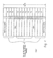
- the MCN 7000 is an advanced network element available from Marconi Communications. As illustrated in figure 2 , the MCN 7000 20 is a platform comprising many CPU-based elements. Each element is identifiable by a unique serial number. Each element is also housed inside the upper deck 21 or the lower deck 23 in the MCN 7000 enclosure 22.
- the top deck 21 comprises fourteen slots, six reserved for the common modules (System and Network processors, Cross-Connect matrix, etc%) and eight slots for optical modules (OC-3/12/48/192).
- the bottom deck 33 comprises sixteen slots that can be used either for electrical (DS1, E1, DS3, EC-1) or for optical modules (OC3/12/48). Of these sixteen traffic-carrying slots, two can be used to protect electrical signal mappers in any mix (DS1, E1, DS3, EC-1), with a 1:6 protection ratio. Twelve slots have electrical interfacing capabilities in two groups of six and the two remaining slots are used to relay traffic to the appropriate protection mappers. More details on the MCN 7000 are described later in this disclosure.
- the hardware provider is the entity that owns the network element and that sells all or portions of the functionality of the network element to a service provider.
- the service provider is an entity that purchases all or substantial portions of the functionality of the network element from the hardware provider and that in turn resells smaller portions of the functionality to end users.
- the end users are the entities that actually use the functionality and services provided by the network element.
- the exemplary embodiment will also be presented with reference to an optical mapper within the MCN 7000 for use with SONET/SDH digital data streams.
- the optical mapper comprises a dual rate, four-port OC-3/OC-12 module.
- the module has up to four ports that can be operated, independently of each other, either as OC-3 or OC-12.
- SP system processor
- SMCU System Control Unit
- a service provider may initially desire to purchase network equipment and software that has one level of functionality but with the capability of being upgraded in the future to different capabilities as the demand for the service provider's network services change.
- the present invention provides a mechanism and method whereby a hardware provider can provide to a service provider network elements having high levels of functionality but with the use of that functionality controllable via the softkey concept of the present invention.
- a service provider may purchase six network elements to establish the communication network shown in figure 5 .
- the interconnection shown is preferably based on optical links, such as OC-3 (155 Mb/s) SONET links.
- optical links such as OC-3 (155 Mb/s) SONET links.
- OC-3 155 Mb/s
- network element #4 and network element #6 are each equipped with optical mappers, each optical mapper being capable of servicing four communication channels at an OC-3 or OC-12 data rate.
- the service provider may have initially purchased the right to use less than all of the available channels of these optical mappers and purchased the right to operate the channels at OC-3 data rate.
- the softkeys concept of the present invention provides the hardware provider a mechanism and method for upgrading the service provider's purchased equipment to include all of the available channels and the right to operate the channels at OC-12 without having to physically go to the equipment room where the network elements are located to either install hardware or software or to manually enter hardware or software keys. This is advantageous because, among other things, the network elements may be housed remotely and they may not be readily accessible.
- the softkeys concept of the present invention allows the hardware provider to remotely control the features and functions of the network element as the service provider's needs change. This can add up to great operational savings in dispatching personnel as well as providing efficient and quick service deployment.
- network elements #4 and #6 could have been initially sold by the hardware provider to the software provider having a configuration that is limited to one mapper working with two channels at OC-3 rates.
- the service provider would purchase two softkeys to obtain the authorization to use two channels at OC-3 rates on the mapper. Later, when the service provider wishes to add more channels or to change the bit-rate, the service provider can purchase additional softkeys to enable the use of the desired features.
- the EMS 32 is a device used by the service provider to manage the network. It preferably is a PC with software for communicating with the NE via a LAN 34. In the exemplary embodiment, the EMS also communicates with the other network elements (NEs) through the existing network communication path 30. Alternatively, however, a LAN network could be used to interconnect each NE to the EMS workstation 32.
- the service provider can install the softkeys purchased from the hardware supplier and use the EMS to activate the link between NE#4 and NE#6.
- the EMS 32 as shown in figure 5 , also preferably includes the capability to graphically represent the state of the network.
- Figure 6 is a state diagram illustrating the preferred method for installing, removing and upgrading softkeys for enabling the link between Nodes #4 and #6.
- the figure depicts the process through a series of steps (Steps 1 through Steps 27) in the state diagram table. Included in the process are interactions between the service provider, the hardware supplier softkey database, the EMS and its associated database, the SP in the NE and its associated database, and the port of the circuit module being activated.
- step 1 the service provider issues a command to the EMS attempting to provision port #2, on circuit pack #5 on NE#4.
- Circuit pack #5 in this example is the circuit module having functions that will be activated.
- step 2 because the service provider does not provide a softkey with the command for provisioning that circuit pack/port number, the EMS responds to the service provider with a request denied indication.
- step 3 the service provider requests an unassigned softkey from the hardware supplier database.
- an unassigned OC-3 key is available because the service provider has already purchased it.
- step 4 the hardware supplier database will search its content to verify that no previous keys had been assigned for that circuit pack/port number. Because no previous keys for that circuit pack/port number had been issued, the hardware supplier database system will take the unassigned key, assign it to circuit pack #5, port #2, generate a key value for the key, encrypt the key value, and return an encrypted key value (e.g., K3-452-V1). If the supplier database had found that a previous key had been issued for that service pack, it would have returned a message indicating that a softkey had already been assigned to that circuit pack/port.
- an encrypted key value e.g., K3-452-V1
- the extension "V1" in this exemplary key indicates that the key value was generated using a secure process that results in a key value that is valid once and not reusable for the same circuit pack/port at a different time.
- the secure process is employed to prevent the illegal use of keys once deactivated and returned to the hardware database.
- a service provider could purchase a softkey to enable a port, disable the port and return the softkey in exchange for a new softkey value to enable a different port on a different or same circuit pack, and then re-use the first softkey to enable the first port.
- two softkeys could have been deployed in a case where the service provider has only purchased one softkey.
- step 5 the service provider provides the softkey value K3-452-V1 to the EMS software with a command to the EMS to provision port #2, on circuit pack #5.
- the command is valid at this time because the EMS is supplied with a softkey.
- step 6 the EMS accepts the command and issues a complementary command with the softkey value to the SP to activate the requested port.
- the SP issues a complementary command with the softkey value to circuit pack #5 to activate the port.
- the circuit pack runs a decryption algorithm to decode the key value and checks the value of an internal counter. The circuit pack then validates the key value using the counter value. Because the key value is valid, the circuit pack installs at least a portion of the key value in a special key receptacle on board the circuit pack which unlocks the feature.
- the circuit pack returns a message when the port has been activated. The SP forwards this message to the EMS which in turn returns a confirmation message to the service provider. This is the end of this sequence.
- the hardware provider softkey database contains an assigned OC-3 key K3-452-V1. The same process is repeated to activate the corresponding port on NE#6.
- FIG. 6 An exemplary method for upgrading the same link from OC-3 to OC-12 is shown in figure 6 beginning at step 13. For the purposes of this example, it is assumed that the service provider is starting with the part of the link NE#4 to NE#6, and will continue with the conversion of the remainder of the ring afterward.
- the service provider issues a command to the EMS to deactivate port #2, on circuit pack #5 of NE#4.
- the EMS issues a command to NE#4 to deactivate the port.
- the SP issues a complementary command to the circuit pack to deactivate the port.
- the circuit pack deactivates the port, removes the key value from the key receptacle, increments the internal counter, generates a removed key value DK3-452-V1 and returns the removed key value DK3-452-V1 to the SP.
- the removed key value is also encrypted.
- the SP returns a confirmation message to the EMS with the removed key value.
- the EMS stores the removed key value in a database.
- the removed key value is calculated using an algorithm that corresponds to a removed key algorithm running in the hardware supplier database.
- At least a portion of the prior key value K3-452-V1, in particular the interval counter value, "V1" is "remembered” by the circuit pack, i.e., it is stored in a non-volatile, non-destructible and non-user-accessible part of the circuit pack's memory.
- the prior key value is used by the key generation algorithm to calculate a new key value the next time it has to validate a key when the EMS attempts to install a key value.
- the EMS use in this example is one variant of the present invention. The invention can be carried out without using an EMS.
- the EMS returns the confirmation to the service provider that the port has been deactivated.
- the removed key value is returned to the service provider.
- the service provider sends a command to the hardware provider softkey database to unassign the OC-3 key and returns the removed key value DK3-452-V1.
- the hardware provider softkey database remembers at least a portion of the unassigned key value K3-452-V1, in particular the interval counter value, to use in its key generation algorithm the next time it has to generate a key for activating port #2, on circuit pack #5.
- the hardware provider softkey database returns a confirmation message.
- the hardware provider softkey database contains an unassigned OC-3 key ⁇ K3 ⁇ with internal counter value K3-452-V1 remembered.
- the service provider requests a new softkey to reflect an upgrade in service from OC-3 to OC-12.
- the hardware provider can provide keys in a number of ways.
- the service provider sends the hardware provider a purchase order, and the hardware provider after receiving it, generates an unassigned OC-12 softkey.
- the hardware provider's database reflects the change: a new key ⁇ K12 ⁇ is available. Whether the old key ⁇ K3 ⁇ is retained by the service provider or returned to the hardware provider for some type of credit is an implementation feature of the database that reflects business operations. Another option is to buy a new key ⁇ K12 ⁇ without removing the ⁇ K3 ⁇ key.
- Various means could be used to inform the service provider. In this example, no message is sent back, but when the service provider checks his service provider area, it will notice the appearance of the new softkey. At this point the hardware provider softkey database contains an unassigned OC-12 key ⁇ K12 ⁇ and at least a portion of the value K3-452-V1, the interval counter in particular, is remembered.
- step 21 the process for activating the OC-12 port is similar to the steps taken in steps 3 through 7 to activate the OC-3 port.
- the service provider requests that an OC-12 key be assigned for circuit pack#5, port#2.
- the hardware provider database searches its content for an assignment based on circuit pack#5, port#2. If it finds one, it returns a negative message. If it finds none, then using an algorithm, it generates an encrypted key value which is shown as K12-452-V33.
- the hardware provider uses an algorithm to generate a new key value much in the same manner as described above with respect to the OC-3 key generation.
- the OC-12 algorithm can be adapted so that the first OC-12 key value will be different from the first key value of the OC-3 key or any other key.
- the service provider provides the softkey value K12-452-V33 to the EMS software with a command to the EMS to provision port #2, on circuit pack #5.
- the EMS accepts the command and issues a complementary command with the softkey value to the SP to activate the requested port.
- the SP issues a complementary command with the softkey value to circuit pack #5 to activate the port.
- the circuit pack runs a decryption algorithm to decode the key value and checks the value of an internal counter. The circuit pack then validates the key value using the counter value. Because the key value is valid, the circuit pack installs at least a portion of the key value in a special key receptacle on board the circuit pack which unlocks the feature.
- the circuit pack returns a message when the port has been activated. The SP forwards this message to the EMS which in turn returns a confirmation message to the service provider. This is the end of this sequence.
- the hardware provider softkey database contains an assigned OC-12 key K12-452-V33 and the internal counter value of K3-452-V1, in particular the value "V1 ", is remembered on the same port for future use if an OC-3 softkey were to be installed. The same process is repeated to activate the corresponding port on NE#6.
- the softkey is, therefore, an entity that can be assigned a value for use in locking or unlocking features in a network.
- a hardware provider can sell a key to a service provider and when the service provider is ready to use the softkey, it can request that the hardware provider database system assign a value to the key.
- the softkey can be reused in the system once the used service is deactivated and an unassigned key value is returned.
- Another function of one embodiment of the present invention is the system's ability to allow a user to begin using a feature without it being authorized and then later obtaining authorization to continue to use the feature. For example, if a service provider had the need for a network service at a time when the hardware provider was not available to provide a softkey to authorize the use, such as over a weekend, the system allows the service provider to use the service over the weekend and to obtain the softkey to authorize the use on Monday when the hardware provider was available.
- the software provider could issue a command to begin using the network service provided by the network element.
- the network element could allow the use of the service but issue a major alarm that could not be masked.
- the service provider could use the service but would be inconvenienced by having an on-going major alarm condition.
- the service provider would only be able to turn off the major alarm once it purchases a softkey and uses the softkey to authorize the use of the network service.
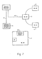
- the system comprises a hardware provider database 40 and a plurality of NEs 42.
- the service provider has a means for communicating with both the hardware provider database 40 and the NEs 42.
- the hardware provider database 40 is accessible via the Internet, and the service provider using a PC and Internet access path 44, such as modem, DSL line, LAN connection, and others, can securely exchange softkey information with the database 40.
- the service provider also can communicate with the NEs 42 using a conventional communication path 46 such as a dial-up, LAN or direct connection.
- the service provider can obtain key values for its purchased keys and transmit those key values to the NEs 42 to command service modules 48 contained within the NEs 42 to activate their service module functions.
- the service modules 48 could optionally be hardware modules, software modules, or combinations of hardware and software.
- a preferred design and implementation of the softkey concept of the present invention will be described next. Described below is an example of: (A) how a softkey value could be defined; (B) how softkeys can be processed; and (C) the user interface (or commands) to deal with the softkeys. Sections (D) through (G) then describe further implementation details for using the invention with a Quad OC-3/OC-12 optical mapper card that may be included in an ADM such as the MCN 7000.
- This implementation of a softkey includes two unique attributes: (1) a key activation value that is good for one use only; and (2) when a key is retracted (or de-activated), the value displayed for the key serves as proof of the return since it can be checked with a validation algorithm.
- the softkey value have the following parameters: (i) a card serial number; (ii) a given facility type (OC-3 or OC-12); (iii) a given port number (from 1 to the maximum of the card: 4 for the Quad OC-3/OC-12 card); (iv) a sequence number (internal counter); and (v) lock status.
- a card serial number in the case of the Quad OC-3/12 card, one variant defines up to eight softkeys based on facility plus port number which yields eight keys. Another variant defines up to four softkeys based on facility and two ports at a time. The serial number is used to identify the specific card interface while the internal sequence number is used for security as described above.
- a softkey is linked to a card, not to a shelf. Hence, if a card is moved from one slot to another or even from one shelf to another, its keys move with it. No additional provisioning is required.
- the softkey have two additional attributes that are hidden from a user: lock status and sequence number.
- the lock status indicates if the key has been activated (facility unlocked) or not activated (facility locked).
- the sequence number represents a counter value for the number of times that the key has been activated and deactivated.
- the internal sequence number is preferably stored on the card or service module with no user access and also stored with the hardware provider database system.
- each key needs to be activated to be effective.
- the facility corresponding to the key cannot be used until the key is activated.
- the facility can be used before the key is activated but, if the key is not activated and the corresponding facility within the network element is used, the network element will consider the traffic that is being passed as illegal. The network element will then generate a major alarm. This alarm will not be cancelable and will mask all other alarms that relate to the facility. The alarm can only be cleared when they proper key is entered (or the facility is not used anymore).
- a key may be de-activated if the facility is not needed anymore and the service provider wants to return the key to the hardware provider database system.
- a key may be activated/ de-activated as many times as needed.
- the Basic User Interface for softkeys is based on TL1 commands as an example. Three commands are defined to deal with the softkeys: (i) one to activate a key, (ii) one to de-activate a key, and (iii) last one to show the current key lock value.
- the 'softkey' alarm is raised when a facility is provisioned and the corresponding key has not been activated previously.
- the 'softkey' alarm is cleared when the corresponding key is activated or the facility is de-provisioned.
- the raised 'softkey' alarm will mask all alarms for the related facility.
- the name of the alarm preferably is "Feature not authorized”.
- the alarm preferably is not programmable and it can not be masked or canceled.
- the recommended severity is MJ (major).
- the QUAD OC-3/OC-12 keys attributes are stored into the card's EEPROM.
- An exemplary memory map of the softkey area is as follows: Offset Data item 0010 Port 1, OC-3, Key sequence number 0020 Port 1, OC-3, Key lock status 0030 Port 1, OC-12 Key sequence number 0040 Port 1, OC-12, Key lock status 0050 Port 2, OC-3, Key sequence number 0060 Port 2, OC-3, Key lock status 0070 Port 2, OC-12, Key sequence number 0080 Port 2, OC-12, Key lock status 0090 Port 3, OC-3, Key sequence number 00A0 Port 3, OC-3, Key lock status 00B0 Port 3, OC-12, Key sequence number 00C0 Port 3, OC-12, Key lock status 00D0 Port 4, OC-3, Key sequence number 00E0 Port 4, OC-3, Key lock status 00F0 Port 4, OC-12, Key sequence number 0100 Port 4, OC-12, Key lock status
- the proposed implementation provides flexibility to a user of the system.
- the user may purchase at any time, any channel, bit rate combination needed. But even more, the implementation offers the capability to return a previously purchased key.
- a key may be activated, de-activated any number of times.
- the system is secure since a key value is only valid once. Using the de-activated key value as proof of return is also a secure/easy way to guarantee that the de-activation as been performed.
- the exemplary MCN 7000 20 may be equipped with the following components: an ACIU module 50, an NMCU module 52, a SMCU module 24, one cross connect such as an XCON 20G module, an XCON 40G module, or an XCON 60G module, an OC-192 module, an OC-48 module, a Quad OC-3/12 module, a DS3 module, a DS3/EC-1 module, a DS-1 module, an Ethernet module, a fast Ethernet module, a Gigabit Ethernet Module, a multi-link data module, a VPP module, a PSCU module, and/or a TIU module.
- an ACIU module 50 an NMCU module 52
- a SMCU module 24 one cross connect such as an XCON 20G module, an XCON 40G module, or an XCON 60G module, an OC-192 module, an OC-48 module, a Quad OC-3/12 module, a DS3 module, a DS3/EC-1 module, a
- the ACIU module 50 is the Alarm and Craft interface Unit (ACIU). This module controls system alarms.
- the NMCU module 52 is the Network Management and Control Unit. This module manages all system communications (TL1, Ethernet, DCC, etc%) with the outside world.
- SMCU module 24 is the System Management and Control Unit. This module manages all system provisioning, maintenance and alarm reporting.
- the XCON 20G module provides the traffic connections for all traffic-carrying and protection slots of the MCN 7000 system.
- This module is capable of cross-connecting an aggregated traffic density of 20 Gb/s (non-blocking). On the top deck, it provides 4 slots with STS-48 connections and 2 slots with STS-12 connections. On the bottom deck, it provides 14 slots with STS-12 connections.
- the XCON 40G module provides the traffic connections for all traffic-carrying and protection slots of the MCN 7000 system.
- This module is capable of cross-connecting an aggregated traffic density of 40 Gb/s (non-blocking). On the top deck, it provides 8 slots with STS-48 connections. On the bottom deck, it provides 6 slots with STS-48 connections and 8 slots with STS-12 connections.
- the XCON 60G module provides the traffic connections for all traffic-carrying and protection slots of the MCN 7000 system.
- This module is capable of cross-connecting an aggregated traffic density of 60 Gb/s (non-blocking).
- On the top deck it provides 4 slots with STS-192 connections and 4 slots with STS-48 connections (not available with double-width OC-192 modules).
- On the bottom deck it provides 6 slots with STS-48 connections and 8 slots with STS-12 connections.
- the OC-192 module supports one OC-192 channel with pointer processing to STS-1 level.
- the OC-192 module can be installed in any of the four OC-192 slots. Up to four (4) OC-192 modules can be installed in an MCN 7000 system.
- the OC-48 module supports one OC-48 channel with pointer processing to STS-1 level.
- the OC-48 module can be installed in any traffic-carrying slots (slots U1-U8 and L1-L14). Up to twenty-two (22) OC-48 modules can be installed in an MCN 7000 system.
- the Quad OC-3/12 module supports four channels that can be operated at OC-3 or OC-12 rates with pointer processing to STS-1 level.
- the Quad OC-3/12 module can be installed in any traffic-carrying slots (slots U1-U8 and L1-L14). Up to twenty-two (22) Quad OC-3/12 modules can be installed in an MCN 7000 system.
- the DS3 module supports eight (8) ITU-T compliant G.703/G.704 DS3 channels.
- the DS3 module can be installed in any of the traffic-carrying and protection slots of the bottom deck. Up to twelve (12) DS3 working modules and two (2) DS3 protection module can be installed in an MCN 7000 system.
- the DS3/EC-1 module provides eight (8) Telcordia compliant GR-499 (D53) and GR-253 (EC-1) DS3/EC-1 channels.
- the DS3/EC-1 module can be installed in any of the traffic-carrying and protections slots of the bottom deck. Up to twelve (12) DS3/EC-1 working modules and two (2) DS3/EC-1 protection modules can be installed in a MCN 7000 system.
- the DS1 module supports twenty-eight (28) ITU-T compliant G.703/G.704 DS1 channels.
- the DS1 module can be installed in any of the traffic carrying and protections slots of the bottom deck. Up to twelve (12) DS1 working modules and two (2) DS1 protection module can be installed in a MCN 7000 system.
- This Packet over SONET (POS) module is used to provide Transparent LAN services (TLS) and Router Port Extension (RPE).
- the Ethernet module can be installed in any of the traffic carrying and protections slots of the bottom deck. Up to twelve (12) Ethernet modules can be installed in a MCN 7000 system and can be protected using a 1+1 scheme.
- the Fast Ethernet Module supports eight 100BaseTx RJ45 Fast Ethernet ports and maps them into STS-1 or STS-3c.
- This Packet over SONET (POS) module is used to provide Transparent LAN services (TLS) and Router Fort Extension (RPE).
- the Fast Ethernet module can be installed in any of the traffic carrying and protections slots of the bottom deck. Up to twelve (12) Fast Ethernet modules can be installed in a MCN 7000 system and can be protected using a 1+1 scheme.
- This Packet over SONET (POS) module is used to provide Transparent LAN services (TLS) and Router Port Extension (RPE).
- the Gigabit Ethernet module can be installed in any traffic-carrying slots. Up to twenty (20) Gigabit Ethernet modules can be installed in a MCN 7000 system and can be protected using a 1+1 scheme.
- the Multi-link Data module provides 126 MLPPP/Frame Relay DS1/E1 mapped into 120 VT1.5 (VC-11) VT2 (VC-12) termination to Packet Over SONET (POS) over an STS-3c frame.
- POS Packet Over SONET
- Up to ten (10) 1+1 protected or twenty (20) unprotected Multi-link Data modules can be installed, each fitting in any of the traffic-carrying slots of the MCN 7000 system.
- the VPP module provides the capability of terminating and pre-grooming 4 PacketPath Virtual Rings of variable speed in order to send the packets to the data switch. It is used in hubbing applications where the MCN 7000 terminates a large number of rings. A1+1 protection scheme is available.
- the Protection Switching and Control Unit (PSCU) module supports protection switching for up to six (6) working modules.
- PSCU One type of PSCU module, the PSCU DS1/E1, offers 1:6 protection for up to six DS1/E1 modules.
- PSCU DS3/EC-1 Another type of PSCU module, the PSCU DS3/EC-1, offers 1:6 protection for up to six DS3/EC-1 modules.
- the Tributary Interface Unit (TIU) module is passive and provides the connection points for the electrical signals such as DS1, E1, DS3, and Ethernet at the rear of the shelf. Twelve TIU modules can be installed in TIU slots of the MCN 7000 system. The five variants of the TIU are: (1) TIU DS1 provides the connection points for 28 DS1 interfaces; (2) TIU E1 provides the connection points for 28 E1 interfaces; (3) TIU D53/EC-1 provides the connection points for 8 D53/EC-1 interfaces; (4) TIU Ethernet provides the connections points for 24 Ethernet interfaces; and (5) TIU Fast Ethernet provides the connections points for 8 Fast Ethernet interfaces.
Landscapes
- Engineering & Computer Science (AREA)
- Computer Security & Cryptography (AREA)
- Computer Networks & Wireless Communication (AREA)
- Signal Processing (AREA)
- Computer Hardware Design (AREA)
- Computing Systems (AREA)
- General Engineering & Computer Science (AREA)
- Data Exchanges In Wide-Area Networks (AREA)
- Small-Scale Networks (AREA)
- Mobile Radio Communication Systems (AREA)
- Selective Calling Equipment (AREA)
Claims (34)
- Netzelement (42) mit einer Mehrzahl von Merkmalen, wobei wenigstens eines der Merkmale optional aktiviert oder deaktiviert werden kann, und das Netzelement (42) umfasst:ein Servicemodul (48), das ein erstes Netzmerkmal bereitstellt, das optional aktiviert oder deaktiviert werden kann;einen Systemprozessor (SP), der so betrieben werden kann, dass er einen Softkey-Wert empfängt, der von außerhalb des Netzelements eingegeben wird, wobei ein Softkey eine programmierbare Software-Taste ist, die verwendet wird, um ein bestimmtes Software-Element zu aktivieren, um es auszuführen; undein Softkey-Validierungssystem, das so betrieben werden kann, dass es die Verwendung des ersten Netzmerkmals aktiviert, wenn der empfangene Softkey-Wert derselbe wie ein erster gültiger Softkey-Wert ist, wobei das Softkey-Validierungssystem außerdem so betrieben werden kann, dass es die Verwendung des ersten Netzmerkmals ein zweites Mal aktiviert, nachdem das erste Netzmerkmal deaktiviert wurde, wenn der empfangene Softkey-Wert derselbe wie ein zweiter gültiger Softkey-Wert ist, wobei der erste gültige Softkey-Wert nicht derselbe wie der zweite gültige Softkey-Wert ist, und das Softkey-Validierungssystem umfasst:Speicher zum Speichern von Informationen bezüglich des Servicemoduls; undeinen Algorithmus zur Verwendung bei der Bestätigung, ob der empfangene Softkey-Wert ein gültiger Softkey-Wert ist;wobei bei Bestätigung, dass der empfangene Softkey-Wert gültig ist, das Softkey-Validierungssystem die Verwendung des Netzmerkmals aktiviert.
- Netzelement (42) nach Anspruch 1, wobei das Aktivieren der Verwendung des Netzmerkmals ein Aktivieren der Verwendung des Netzmerkmals ohne die Erzeugung von Alarmen umfasst.
- Netzelement (42) nach Anspruch 1, wobei das Aktivieren der Verwendung des Netzmerkmals ein Aktivieren der Verwendung des Netzmerkmals selbst in einem Alarmzustand umfasst, wenn das Netzmerkmal nicht verwendet werden könnte, ohne durch das Softkey-System aktiviert zu werden.
- Netzelement (42) nach Anspruch 1, wobei der Algorithmus zum Erzeugen eines Softkey-Deaktivierungswertes angewendet werden kann, wenn das erste Netzmerkmal deaktiviert wurde.
- Netzelement (42) nach Anspruch 1, wobei das Servicemodul ein Kommunikationsmodul ist.
- Netzelement (42) nach Anspruch 5, wobei das erste Netzmerkmal ein Kommunikationsanschluss ist.
- Netzelement (42) nach Anspruch 6, wobei das erste Netzmerkmal ein OC-3-Anschluss ist.
- Netzelement (42) nach Anspruch 6, wobei das erste Netzmerkmal ein OC-12-Anschluss ist.
- Netzelement (42) nach Anspruch 6, wobei das erste Netzmerkmal ein OC-48-Anschluss ist.
- Netzelement (42) nach Anspruch 6, wobei das erste Netzmerkmal ein OC-192-Anschluss ist.
- Netzelement (42) nach Anspruch 6, wobei das erste Netzmerkmal ein EC-1-Anschluss ist.
- Netzelement (42) nach Anspruch 6, wobei das erste Netzmerkmal ein DS3-Anschluss ist.
- Netzelement (42) nach Anspruch 6, wobei das erste Netzmerkmal ein DS1-Anschluss ist.
- Netzelement (42) nach Anspruch 6, wobei das erste Netzmerkmal ein E1-Anschluss ist.
- Netzelement (42) nach Anspruch 6, wobei das erste Netzmerkmal ein Ethernet-Anschluss ist.
- Netzelement (42) nach Anspruch 6, wobei das erste Netzmerkmal ein Fast Ethernet-Anschluss ist.
- Netzelement (42) nach Anspruch 6, wobei das erste Netzmerkmal ein Gigabit Ethernet-Anschluss ist.
- Netzelement (42) nach Anspruch 1, wobei das Servicemodul ein optischer Mapper ist.
- Netzelement (42) nach Anspruch 18, wobei das erste Netzmerkmal ein optischer Netzanschluss ist.
- Netzelement (42) nach Anspruch 1, wobei das Servicemodul ein Softwareprogramm ist.
- Netzelement (42) nach Anspruch 20, wobei das erste Netzmerkmal eine Ausgabe vom Softwareprogramm ist.
- Netzelement (42) nach Anspruch 1, umfassend:Softkey-Zuweisungssystem, das so betrieben werden kann, dass es Operationen in Bezug auf wenigstens einen Softkey durchführt, wobei das Softkey-Zuweisungssystem so betrieben werden kann, dass es dem Softkey einen Softkey-Wert zuweist und den Softkey-Status bei Zuweisung eines Softkey-Wertes zum Softkey auf einen zugewiesenen Zustand aktualisiert, und das Softkey-Zuweisungssystem außerdem so betrieben werden kann, dass es den Softkey-Status bei Empfang eines Softkey-Deaktivierungswertes für den Softkey auf einen nicht zugewiesenen Zustand aktualisiert.
- Netzelement (42) nach Anspruch 22, wobei das Netzelement ferner einen Standardprozessor (SP) umfasst, und wobei der Standprozessor das Softkey-Validierungssystem umfasst.
- Netzelement (42) nach Anspruch 42, wobei das Servicemodul einen internen Zähler umfasst und wobei der interne Zähler einen Wert speichert, der durch das Softkey-Validierungssystem beim Bestimmen verwendet wird, ob der empfangene Softkey-Wert gültig ist.
- Verfahren zum Aktivieren der Verwendung von Netzmerkmalen in einem Netzelement (42) innerhalb eines Netzes, wobei das Netzelement (42) ein Servicemodul (48) umfasst, das ein erstes Netzmerkmal bereitstellt, das optional aktiviert werden kann, und das Verfahren die folgenden Schritte umfasst:Empfangen eines verschlüsselten Softkey-Wertes von außerhalb des Netzelements, wobei ein Softkey eine programmierbare Software-Taste ist, die verwendet wird, um ein bestimmtes Software-Element zu aktivieren, um es auszuführen;Entschlüsseln des verschlüsselten Softkey-Wertes;Bestimmen innerhalb des Netzelements, ob der empfangene Softkey-Wert gleich einem ersten gültigen Softkey-Wert ist;Aktivieren des ersten Netzmerkmals, wenn der empfangene Softkey-Wert gleich dem ersten gültigen Softkey-Wert ist;Bereitstellen eines Mechanismus zum Ableiten eines zweiten gültigen Softkey-Wertes, wobei der zweite gültige Softkey-Wert nicht gleich dem ersten gültigen Softkey-Wert ist, wobei der zweite gültige Softkey-Wert angewendet werden kann, um zu ermöglichen, dass das erste Netzmerkmal aktiviert wird, wenn das erste Netzmerkmal deaktiviert wird, nachdem es unter Verwendung des ersten gültigen Softkey-Wertes aktiviert wurde, und wobei der erste gültige Softkey-Wert nicht angewendet werden kann, um zu ermöglichen, dass das erste Netzmerkmal wieder aktiviert wird, wenn das erste Netzmerkmal deaktiviert wird, nachdem es unter Verwendung des ersten gültigen Softkey-Wertes aktiviert wurde und wenn der empfangene Softkey-Wert derselbe wie der zweite gütige Softkey-Wert ist.
- Verfahren nach Anspruch 25, wobei das Netz ein Softkey-Zuweisungssystem umfasst, und das Verfahren die folgenden Schritte umfasst:Versorgen eines Teilnehmers mit einem wiederverwendbaren Softkey;Erzeugen mit dem Softkey-Zuweisungssystem eines Softkey-Wertes für den Softkey;Verschlüsseln des Softkey-Wertes;Zuweisen des verschlüsselten Softkey-Wertes zu dem Softkey;Liefern des verschlüsselten Softkey-Wertes an den Teilnehmer auf Anforderung des Teilnehmers, um den Softkey zu verwenden;Aktualisieren des Zustands des Softkeys auf einen zugewiesenen Zustand bei Zuweisen des verschlüsselten Softkey-Wertes zu dem Softkey;Bereitstellen eines Verfahrens, um es dem Teilnehmer zu ermöglichen, den Softkey in einen nicht zugewiesenen Zustand zurückzuversetzen; undErmöglichen, dass der Teilnehmer den Softkey zum Aktivieren eines zweiten Netzmerkmals wiederverwendet, indem es dem Softkey-Zuweisungssystem ermöglicht wird, den Teilnehmer auf Anforderung mit einem zweiten Softkey-Wert zu versehen, wenn der Softkey zum Zeitpunkt der Anforderung in einem nicht zugewiesenen Zustand ist.
- Verfahren nach Anspruch 26, wobei die Bereitstellung eines Verfahrens, um es einem Teilnehmer zu ermöglichen, den Softkey-Schritt zurückzusetzen, die folgenden Schritte umfasst:Bereitstellen innerhalb des Netzelements eines Systems zum Deaktivieren des Merkmals, das mit dem installierten Softkey assoziiert ist, und zum Zurückgeben an den Teilnehmer eines Tasten-Deaktivierungswertes bei Deaktivierung des Merkmals;Akzeptieren des Tasten-Deaktivierungswertes vom Teilnehmer; undAktualisieren des Zustands des Softkeys, um widerzuspiegeln, dass er in einem nicht zugewiesenen Zustand ist.
- Verfahren nach Anspruch 26, wobei das System zum Ableiten eines zweiten Softkey-Wertes einen Zähler innerhalb des Servicemoduls (48) umfasst, der die Anzahl von Malen beobachtet, die das Servicemodulmerkmal deaktiviert wurde.
- Verfahren nach Anspruch 26, wobei das System zum Ableiten eines zweiten Softkey-Wertes einen Zähler innerhalb des Servicemoduls (48) umfasst, der die Anzahl von Malen beobachtet, die das Servicemodulmerkmal aktiviert wurde.
- Verfahren nach Anspruch 26, wobei das Servicemodul einen Tastenhalteort umfasst und wobei das erste Netzmerkmal durch Laden wenigstens eines Teils des gültigen Tastenwertes in den Tastenhalteort aktiviert wird.
- Verfahren nach Anspruch 26, wobei das Servicemodul (48) einen Tastenhalteort umfasst und wobei das erste Netzmerkmal aktiviert wird, indem Daten, die von wenigstens einem Teil des gültigen Tastenwertes abgeleitet sind, in den Tastenhalteort geladen werden.
- Verfahren nach Anspruch 25, wobei das Netzelement (42) das Servicemodul (48) umfasst, welches das erste Netzmerkmal bereitstellt, das optional bewilligt werden kann, wobei das Verfahren die folgenden Schritte umfasst:Ermöglichen, dass ein Teilnehmer das erste Netzmerkmal verwendet;Erzeugen eines Alarmzustands, wenn der Teilnehmer das erste Netzmerkmal ohne Zuführen eines Softkey-Wertes verwendet;Versehen eines Teilnehmers mit einem Softkey auf Anforderung durch den Teilnehmer;Erzeugen des Softkey-Wertes für den Softkey;Liefern des Softkey-Wertes an den Teilnehmer auf Anforderung durch den Teilnehmer; undAufheben des Alarmzustands als Reaktion darauf, dass der Teilnehmer den Softkey-Wert dem Netzelement (42) zuführt.
- Verfahren nach Anspruch 32, wobei der Softkey-Wert verschlüsselt wird, und wobei das Netzelement (42) ein Validierungssystem umfasst, das betrieben werden kann, um: (a) den verschlüsselten Softkey-Wert von außerhalb des Netzelements zu empfangen, (b) den verschlüsselten Softkey-Wert zu entschlüsseln, (c) zu bestimmen, ob der empfangene Softkey-Wert gleich einem ersten gültigen Softkey-Wert ist, und (d) die Verwendung des ersten Netzmerkmals zu bewilligen, wenn der empfangene Softkey-Wert gleich dem ersten gültigen Softkey-Wert ist.
- Verfahren nach Anspruch 32, wobei das Servicemodul (48) ein System zum Ableiten eines zweiten gültigen Softkey-Wertes umfasst, wobei der zweite gültige Softkey-Wert nicht gleich dem ersten gültigen Softkey-Wert ist, wobei der zweite gültige Softkey-Wert angewendet werden kann, um zu ermöglichen, dass das erste Netzmerkmal bewilligt wird, wenn die Bewilligung für das erste Netzmerkmal aufgehoben wird, nachdem es unter Verwendung des ersten gültigen Softkey-Wertes bewilligt wurde, und wobei der erste gültige Softkey-Wert nicht angewendet werden kann, um zu ermöglichen, dass das erste Netzmerkmal wieder bewilligt wird, wenn die Bewilligung für das erste Netzmerkmal aufgehoben wird, nachdem es unter Verwendung des ersten gültigen Softkey-Wertes bewilligt wurde.
Applications Claiming Priority (5)
| Application Number | Priority Date | Filing Date | Title |
|---|---|---|---|
| US20982100P | 2000-06-06 | 2000-06-06 | |
| US209821P | 2000-06-06 | ||
| US22307800P | 2000-08-04 | 2000-08-04 | |
| US223078P | 2000-08-04 | ||
| PCT/US2001/018598 WO2001095568A2 (en) | 2000-06-06 | 2001-06-06 | System and method for controlling network elements using softkeys |
Publications (2)
| Publication Number | Publication Date |
|---|---|
| EP1287658A2 EP1287658A2 (de) | 2003-03-05 |
| EP1287658B1 true EP1287658B1 (de) | 2010-08-04 |
Family
ID=26904543
Family Applications (1)
| Application Number | Title | Priority Date | Filing Date |
|---|---|---|---|
| EP01942109A Expired - Lifetime EP1287658B1 (de) | 2000-06-06 | 2001-06-06 | System und verfahren zur steuerung von netzwerkelementen unter verwendung von programmierbaren tasten |
Country Status (7)
| Country | Link |
|---|---|
| US (1) | US7058972B2 (de) |
| EP (1) | EP1287658B1 (de) |
| AT (1) | ATE476819T1 (de) |
| AU (1) | AU2001275402A1 (de) |
| CA (1) | CA2412430C (de) |
| DE (1) | DE60142735D1 (de) |
| WO (1) | WO2001095568A2 (de) |
Cited By (1)
| Publication number | Priority date | Publication date | Assignee | Title |
|---|---|---|---|---|
| US20120102239A1 (en) * | 2009-06-30 | 2012-04-26 | Telefonaktiebolaget L M Ericsson (Publ) | Method and Arrangement Handling Pluggable Modules and Operating Modes in a Media Converter System |
Families Citing this family (9)
| Publication number | Priority date | Publication date | Assignee | Title |
|---|---|---|---|---|
| US20100042927A1 (en) * | 2000-07-03 | 2010-02-18 | Kim Steven D | Third Party Management of Computer System Control |
| US20020124168A1 (en) * | 2000-07-17 | 2002-09-05 | Mccown Steven H. | Method and system for upgrading a user environment |
| US7058649B2 (en) * | 2001-09-28 | 2006-06-06 | Intel Corporation | Automated presentation layer content management system |
| WO2003062842A1 (en) * | 2002-01-23 | 2003-07-31 | Appian Communications, Inc. | Managing virtual network architectures |
| US20040131072A1 (en) * | 2002-08-13 | 2004-07-08 | Starent Networks Corporation | Communicating in voice and data communications systems |
| WO2008006403A1 (en) * | 2006-07-12 | 2008-01-17 | Telefonaktiebolaget Lm Ericsson (Publ) | Method, apparatus and computer program product for controlling devices |
| US20080064388A1 (en) * | 2006-09-13 | 2008-03-13 | Helio, Llc. | Softkey access to network connections |
| US9049214B1 (en) * | 2013-11-21 | 2015-06-02 | International Business Machines Corporation | Sharing memory among mobile devices |
| US9992681B2 (en) * | 2015-08-07 | 2018-06-05 | Qualcomm Incorporated | Subsystem for authorization and activation of features |
Citations (1)
| Publication number | Priority date | Publication date | Assignee | Title |
|---|---|---|---|---|
| WO1993011480A1 (en) * | 1991-11-27 | 1993-06-10 | Intergraph Corporation | System and method for network license administration |
Family Cites Families (9)
| Publication number | Priority date | Publication date | Assignee | Title |
|---|---|---|---|---|
| DE69415820T2 (de) * | 1993-09-22 | 1999-08-05 | At&T Corp., New York, N.Y. | Verfahren zum ermöglichen von änderungen der anrufmerkmale in echtzeit für teilnehmer |
| US5943423A (en) * | 1995-12-15 | 1999-08-24 | Entegrity Solutions Corporation | Smart token system for secure electronic transactions and identification |
| US5822415A (en) | 1996-12-02 | 1998-10-13 | Northern Telecom Limited | Method for counting pay per use feature activations in CPE |
| US5896499A (en) * | 1997-02-21 | 1999-04-20 | International Business Machines Corporation | Embedded security processor |
| US5978912A (en) * | 1997-03-20 | 1999-11-02 | Phoenix Technologies Limited | Network enhanced BIOS enabling remote management of a computer without a functioning operating system |
| US6157955A (en) * | 1998-06-15 | 2000-12-05 | Intel Corporation | Packet processing system including a policy engine having a classification unit |
| US6684330B1 (en) * | 1998-10-16 | 2004-01-27 | Tecsec, Inc. | Cryptographic information and flow control |
| US6609207B1 (en) * | 1999-03-02 | 2003-08-19 | International Business Machines Corporation | Data processing system and method for securing a docking station and its portable PC |
| US6587874B1 (en) * | 1999-06-29 | 2003-07-01 | Cisco Technology, Inc. | Directory assisted autoinstall of network devices |
-
2001
- 2001-06-06 EP EP01942109A patent/EP1287658B1/de not_active Expired - Lifetime
- 2001-06-06 AU AU2001275402A patent/AU2001275402A1/en not_active Abandoned
- 2001-06-06 WO PCT/US2001/018598 patent/WO2001095568A2/en not_active Ceased
- 2001-06-06 US US09/875,723 patent/US7058972B2/en not_active Expired - Lifetime
- 2001-06-06 AT AT01942109T patent/ATE476819T1/de not_active IP Right Cessation
- 2001-06-06 DE DE60142735T patent/DE60142735D1/de not_active Expired - Lifetime
- 2001-06-06 CA CA002412430A patent/CA2412430C/en not_active Expired - Lifetime
Patent Citations (1)
| Publication number | Priority date | Publication date | Assignee | Title |
|---|---|---|---|---|
| WO1993011480A1 (en) * | 1991-11-27 | 1993-06-10 | Intergraph Corporation | System and method for network license administration |
Cited By (2)
| Publication number | Priority date | Publication date | Assignee | Title |
|---|---|---|---|---|
| US20120102239A1 (en) * | 2009-06-30 | 2012-04-26 | Telefonaktiebolaget L M Ericsson (Publ) | Method and Arrangement Handling Pluggable Modules and Operating Modes in a Media Converter System |
| US8788722B2 (en) * | 2009-06-30 | 2014-07-22 | Telefonaktiebolaget Lm Ericsson (Publ) | Method and arrangement handling pluggable modules and operating modes in a media converter system |
Also Published As
| Publication number | Publication date |
|---|---|
| WO2001095568A2 (en) | 2001-12-13 |
| DE60142735D1 (de) | 2010-09-16 |
| CA2412430C (en) | 2008-02-26 |
| AU2001275402A1 (en) | 2001-12-17 |
| US7058972B2 (en) | 2006-06-06 |
| EP1287658A2 (de) | 2003-03-05 |
| WO2001095568A3 (en) | 2002-10-24 |
| CA2412430A1 (en) | 2001-12-13 |
| US20020032872A1 (en) | 2002-03-14 |
| ATE476819T1 (de) | 2010-08-15 |
Similar Documents
| Publication | Publication Date | Title |
|---|---|---|
| CA2127080C (en) | Sonet ring subnetwork management method | |
| Maeda | Management and control of transparent optical networks | |
| EP0985298B1 (de) | Verfahren und system zum sichern einer sternnetzverbindung unter verwendung von public key kryptographie | |
| US5996077A (en) | Access control system and method using hierarchical arrangement of security devices | |
| US20050004999A1 (en) | Provisioning a network element using custom defaults | |
| US7058972B2 (en) | System and method for controlling network elements using softkeys | |
| US6959000B1 (en) | Configuration management of a hybrid DCS-SONET ring network | |
| US7170851B1 (en) | Systems and methods for automatic topology provisioning for SONET networks | |
| JP2013501389A (ja) | 光ネットワーク終端装置管理制御インターフェースベースの受動光ネットワークセキュリティ強化 | |
| US6934262B1 (en) | Method and apparatus for restricting the assignment of VLANs | |
| US7002907B1 (en) | System and methods for automatic equipment provisioning for SONET networks | |
| US7058012B1 (en) | Systems and methods for automatic end-to-end path provisioning for SONET networks | |
| US7124368B1 (en) | System and method for displaying usage information in a data network | |
| WO2011046752A1 (en) | Systems and methods for license entitlement key distribution | |
| US20030035173A1 (en) | Interconnecting processing units of a stored program controlled system using time division muliplexed free space optics | |
| US6738825B1 (en) | Method and apparatus for automatically provisioning data circuits | |
| US7734759B2 (en) | Cross-connect protection method, network management terminal, and network element | |
| US7054277B1 (en) | Method and apparatus for preventing loops within a data stitching network element | |
| CN120224197A (zh) | 一种可一键无线配对的同步系统及同步方法 | |
| EP2002620A2 (de) | Multifunktionale linienkarte für metro-optische anwendungen | |
| CN117040846B (zh) | 一种接入型otn设备及其数据传输加密和解密方法 | |
| WO2011046750A1 (en) | Systems and methods for a configurable communication device | |
| US7430166B2 (en) | Provisioning Ethernet dual working mode | |
| EP1833184A2 (de) | SONET-Verwaltung und Steuerkanalverbesserung | |
| Rahouma et al. | Applying Smart Security Model to Protect Client Services From the Threats of the Optical Network |
Legal Events
| Date | Code | Title | Description |
|---|---|---|---|
| PUAI | Public reference made under article 153(3) epc to a published international application that has entered the european phase |
Free format text: ORIGINAL CODE: 0009012 |
|
| 17P | Request for examination filed |
Effective date: 20021218 |
|
| AK | Designated contracting states |
Kind code of ref document: A2 Designated state(s): AT BE CH CY DE DK ES FI FR GB GR IE IT LI LU MC NL PT SE TR |
|
| AX | Request for extension of the european patent |
Extension state: AL LT LV MK RO SI |
|
| RAP1 | Party data changed (applicant data changed or rights of an application transferred) |
Owner name: MARCONI INTELLECTUAL PROPERTY (RINGFENCE) INC. |
|
| RAP1 | Party data changed (applicant data changed or rights of an application transferred) |
Owner name: ERICSSON AB |
|
| RAP1 | Party data changed (applicant data changed or rights of an application transferred) |
Owner name: ERICSSON AB |
|
| 17Q | First examination report despatched |
Effective date: 20071220 |
|
| GRAP | Despatch of communication of intention to grant a patent |
Free format text: ORIGINAL CODE: EPIDOSNIGR1 |
|
| RAP1 | Party data changed (applicant data changed or rights of an application transferred) |
Owner name: ERICSSON AB |
|
| GRAS | Grant fee paid |
Free format text: ORIGINAL CODE: EPIDOSNIGR3 |
|
| GRAA | (expected) grant |
Free format text: ORIGINAL CODE: 0009210 |
|
| AK | Designated contracting states |
Kind code of ref document: B1 Designated state(s): AT BE CH CY DE DK ES FI FR GB GR IE IT LI LU MC NL PT SE TR |
|
| REG | Reference to a national code |
Ref country code: GB Ref legal event code: FG4D |
|
| REG | Reference to a national code |
Ref country code: CH Ref legal event code: EP |
|
| REG | Reference to a national code |
Ref country code: IE Ref legal event code: FG4D |
|
| REF | Corresponds to: |
Ref document number: 60142735 Country of ref document: DE Date of ref document: 20100916 Kind code of ref document: P |
|
| REG | Reference to a national code |
Ref country code: NL Ref legal event code: VDEP Effective date: 20100804 |
|
| PG25 | Lapsed in a contracting state [announced via postgrant information from national office to epo] |
Ref country code: NL Free format text: LAPSE BECAUSE OF FAILURE TO SUBMIT A TRANSLATION OF THE DESCRIPTION OR TO PAY THE FEE WITHIN THE PRESCRIBED TIME-LIMIT Effective date: 20100804 Ref country code: FI Free format text: LAPSE BECAUSE OF FAILURE TO SUBMIT A TRANSLATION OF THE DESCRIPTION OR TO PAY THE FEE WITHIN THE PRESCRIBED TIME-LIMIT Effective date: 20100804 Ref country code: AT Free format text: LAPSE BECAUSE OF FAILURE TO SUBMIT A TRANSLATION OF THE DESCRIPTION OR TO PAY THE FEE WITHIN THE PRESCRIBED TIME-LIMIT Effective date: 20100804 |
|
| PG25 | Lapsed in a contracting state [announced via postgrant information from national office to epo] |
Ref country code: CY Free format text: LAPSE BECAUSE OF FAILURE TO SUBMIT A TRANSLATION OF THE DESCRIPTION OR TO PAY THE FEE WITHIN THE PRESCRIBED TIME-LIMIT Effective date: 20100804 Ref country code: PT Free format text: LAPSE BECAUSE OF FAILURE TO SUBMIT A TRANSLATION OF THE DESCRIPTION OR TO PAY THE FEE WITHIN THE PRESCRIBED TIME-LIMIT Effective date: 20101206 |
|
| PG25 | Lapsed in a contracting state [announced via postgrant information from national office to epo] |
Ref country code: BE Free format text: LAPSE BECAUSE OF FAILURE TO SUBMIT A TRANSLATION OF THE DESCRIPTION OR TO PAY THE FEE WITHIN THE PRESCRIBED TIME-LIMIT Effective date: 20100804 Ref country code: SE Free format text: LAPSE BECAUSE OF FAILURE TO SUBMIT A TRANSLATION OF THE DESCRIPTION OR TO PAY THE FEE WITHIN THE PRESCRIBED TIME-LIMIT Effective date: 20100804 Ref country code: GR Free format text: LAPSE BECAUSE OF FAILURE TO SUBMIT A TRANSLATION OF THE DESCRIPTION OR TO PAY THE FEE WITHIN THE PRESCRIBED TIME-LIMIT Effective date: 20101105 |
|
| PG25 | Lapsed in a contracting state [announced via postgrant information from national office to epo] |
Ref country code: DK Free format text: LAPSE BECAUSE OF FAILURE TO SUBMIT A TRANSLATION OF THE DESCRIPTION OR TO PAY THE FEE WITHIN THE PRESCRIBED TIME-LIMIT Effective date: 20100804 |
|
| PG25 | Lapsed in a contracting state [announced via postgrant information from national office to epo] |
Ref country code: IT Free format text: LAPSE BECAUSE OF FAILURE TO SUBMIT A TRANSLATION OF THE DESCRIPTION OR TO PAY THE FEE WITHIN THE PRESCRIBED TIME-LIMIT Effective date: 20100804 |
|
| PLBE | No opposition filed within time limit |
Free format text: ORIGINAL CODE: 0009261 |
|
| STAA | Information on the status of an ep patent application or granted ep patent |
Free format text: STATUS: NO OPPOSITION FILED WITHIN TIME LIMIT |
|
| PG25 | Lapsed in a contracting state [announced via postgrant information from national office to epo] |
Ref country code: ES Free format text: LAPSE BECAUSE OF FAILURE TO SUBMIT A TRANSLATION OF THE DESCRIPTION OR TO PAY THE FEE WITHIN THE PRESCRIBED TIME-LIMIT Effective date: 20101115 |
|
| 26N | No opposition filed |
Effective date: 20110506 |
|
| REG | Reference to a national code |
Ref country code: DE Ref legal event code: R097 Ref document number: 60142735 Country of ref document: DE Effective date: 20110506 |
|
| REG | Reference to a national code |
Ref country code: CH Ref legal event code: PL |
|
| REG | Reference to a national code |
Ref country code: IE Ref legal event code: MM4A |
|
| PG25 | Lapsed in a contracting state [announced via postgrant information from national office to epo] |
Ref country code: LI Free format text: LAPSE BECAUSE OF NON-PAYMENT OF DUE FEES Effective date: 20110630 Ref country code: CH Free format text: LAPSE BECAUSE OF NON-PAYMENT OF DUE FEES Effective date: 20110630 Ref country code: IE Free format text: LAPSE BECAUSE OF NON-PAYMENT OF DUE FEES Effective date: 20110606 |
|
| PG25 | Lapsed in a contracting state [announced via postgrant information from national office to epo] |
Ref country code: MC Free format text: LAPSE BECAUSE OF NON-PAYMENT OF DUE FEES Effective date: 20110630 |
|
| PG25 | Lapsed in a contracting state [announced via postgrant information from national office to epo] |
Ref country code: LU Free format text: LAPSE BECAUSE OF NON-PAYMENT OF DUE FEES Effective date: 20110606 |
|
| PG25 | Lapsed in a contracting state [announced via postgrant information from national office to epo] |
Ref country code: TR Free format text: LAPSE BECAUSE OF FAILURE TO SUBMIT A TRANSLATION OF THE DESCRIPTION OR TO PAY THE FEE WITHIN THE PRESCRIBED TIME-LIMIT Effective date: 20100804 |
|
| REG | Reference to a national code |
Ref country code: FR Ref legal event code: PLFP Year of fee payment: 16 |
|
| REG | Reference to a national code |
Ref country code: FR Ref legal event code: PLFP Year of fee payment: 17 |
|
| REG | Reference to a national code |
Ref country code: FR Ref legal event code: PLFP Year of fee payment: 18 |
|
| PGFP | Annual fee paid to national office [announced via postgrant information from national office to epo] |
Ref country code: FR Payment date: 20190625 Year of fee payment: 19 |
|
| PGFP | Annual fee paid to national office [announced via postgrant information from national office to epo] |
Ref country code: DE Payment date: 20200629 Year of fee payment: 20 |
|
| PGFP | Annual fee paid to national office [announced via postgrant information from national office to epo] |
Ref country code: GB Payment date: 20200629 Year of fee payment: 20 |
|
| PG25 | Lapsed in a contracting state [announced via postgrant information from national office to epo] |
Ref country code: FR Free format text: LAPSE BECAUSE OF NON-PAYMENT OF DUE FEES Effective date: 20200630 |
|
| REG | Reference to a national code |
Ref country code: DE Ref legal event code: R071 Ref document number: 60142735 Country of ref document: DE |
|
| REG | Reference to a national code |
Ref country code: GB Ref legal event code: PE20 Expiry date: 20210605 |
|
| PG25 | Lapsed in a contracting state [announced via postgrant information from national office to epo] |
Ref country code: GB Free format text: LAPSE BECAUSE OF EXPIRATION OF PROTECTION Effective date: 20210605 |