EP1287262B1 - Vortex shedding and drag force reduction - Google Patents
Vortex shedding and drag force reduction Download PDFInfo
- Publication number
- EP1287262B1 EP1287262B1 EP01934191A EP01934191A EP1287262B1 EP 1287262 B1 EP1287262 B1 EP 1287262B1 EP 01934191 A EP01934191 A EP 01934191A EP 01934191 A EP01934191 A EP 01934191A EP 1287262 B1 EP1287262 B1 EP 1287262B1
- Authority
- EP
- European Patent Office
- Prior art keywords
- elongate body
- protuberances
- fluid flow
- drag
- smoothly curved
- Prior art date
- Legal status (The legal status is an assumption and is not a legal conclusion. Google has not performed a legal analysis and makes no representation as to the accuracy of the status listed.)
- Expired - Lifetime
Links
- 239000012530 fluid Substances 0.000 claims abstract description 41
- 238000000034 method Methods 0.000 claims description 10
- 239000007788 liquid Substances 0.000 claims description 2
- 230000000694 effects Effects 0.000 description 3
- 238000005553 drilling Methods 0.000 description 2
- 230000001939 inductive effect Effects 0.000 description 2
- 229910000831 Steel Inorganic materials 0.000 description 1
- 239000000853 adhesive Substances 0.000 description 1
- 230000001070 adhesive effect Effects 0.000 description 1
- 238000010276 construction Methods 0.000 description 1
- 230000001066 destructive effect Effects 0.000 description 1
- 239000000203 mixture Substances 0.000 description 1
- 230000000737 periodic effect Effects 0.000 description 1
- 238000009420 retrofitting Methods 0.000 description 1
- 239000010959 steel Substances 0.000 description 1
- 238000005728 strengthening Methods 0.000 description 1
- XLYOFNOQVPJJNP-UHFFFAOYSA-N water Substances O XLYOFNOQVPJJNP-UHFFFAOYSA-N 0.000 description 1
Images



Classifications
-
- F—MECHANICAL ENGINEERING; LIGHTING; HEATING; WEAPONS; BLASTING
- F15—FLUID-PRESSURE ACTUATORS; HYDRAULICS OR PNEUMATICS IN GENERAL
- F15D—FLUID DYNAMICS, i.e. METHODS OR MEANS FOR INFLUENCING THE FLOW OF GASES OR LIQUIDS
- F15D1/00—Influencing flow of fluids
- F15D1/10—Influencing flow of fluids around bodies of solid material
- F15D1/12—Influencing flow of fluids around bodies of solid material by influencing the boundary layer
-
- B—PERFORMING OPERATIONS; TRANSPORTING
- B63—SHIPS OR OTHER WATERBORNE VESSELS; RELATED EQUIPMENT
- B63B—SHIPS OR OTHER WATERBORNE VESSELS; EQUIPMENT FOR SHIPPING
- B63B21/00—Tying-up; Shifting, towing, or pushing equipment; Anchoring
- B63B21/50—Anchoring arrangements or methods for special vessels, e.g. for floating drilling platforms or dredgers
- B63B21/502—Anchoring arrangements or methods for special vessels, e.g. for floating drilling platforms or dredgers by means of tension legs
- B63B2021/504—Anchoring arrangements or methods for special vessels, e.g. for floating drilling platforms or dredgers by means of tension legs comprising suppressors for vortex induced vibrations
Definitions
- This invention relates to techniques for modifying fluid flow so as to reduce the effects of drag and vortex shedding. More particularly, this invention relates to such techniques that may be applied to elongate bodies.
- a drag force is exerted on the elongate body and vortex shedding can occur inducing forces that can lead to undesirable vibration.
- the drag force of passing fluid flow often means that the elongate body has to be produced with a strengthened structure to resist such a drag force.
- the cost of strengthening the structure in this way can be significant.
- the forces this exerts vary with time in a manner that can establish highly damaging undesirable vibrations within an elongate body. It may be that these vibrations will stimulate a resonance with potentially destructive consequences.
- fairings It is known to fit fairings to structures in order to modify fluid flow around those structures to reduce drag.
- a problem with such fairings is that they are usually only able to cope with fluid flow from a single direction and if the fluid flow direction changes, then they may be ineffective, or in fact increase drag.
- the fairings may be made movable to accommodate different flow directions, but this disadvantageously increases their cost and complexity.
- US-A-4,059,129 discloses a cylindrical body with a plurality of small planes extending from its outer surface acting as vortex generators to reduce vibrations due to transverse flow against the body.
- the present invention provides an elongate body having a plurality of longitudinally spaced apart smoothly curved protuberances extending therefrom, said protuberances having a surface which is smoothly curved in two orthogonal directions, said elongate body having a maximum cross-section excluding said protuberances of D, said protuberances extending from an outer surface of said elongate body excluding said protuberances by a distance within the range 0.1D to 0.75D inclusive, and said protuberances being shaped and dimensioned to modify fluid flow substantially transverse against the outside of said elongate body around said elongate body in a manner that reduces forces upon said elongate body produced by drag substantially in the flow direction and by vortex shedding substantially normal to the flow direction.
- the invention recognises and exploits the phenomenon whereby a smoothly curved protuberance (smooth at least in the sense of how it modifies the fluid flow) from an elongate body can be made to modify the fluid flow around that body in a manner that reduces the forces exerted on the body by drag and vortex shedding.
- the protuberance is advantageously simple and inexpensive to provide with or add to an elongate body.
- said protuberances extend in a plurality of different radial directions from a longitudinal axis of said elongate body.
- This feature of the invention allows fixed protuberances that are inexpensive and simple to reduce drag and vortex shedding that can occur from fluid flow incident from any radial direction around the elongate body. This is strongly advantageous since, for example, a chimney or a drilling platform leg may be subject to fluid flow from any radial direction.
- the differences between the radial direction of adj acent protuberances may vary over a range of values. It has been found that a preferred range of values for the differences between radial directions is 30 degrees to 90 degrees inclusive. A particularly preferred arrangement that works well in many cases is when the difference in radial direction between adjacent protuberances is substantially 45 degrees.
- the protuberances could be applied to a single side of the elongate body. However, in preferred embodiments the protuberances are arranged in pairs at the same longitudinal position along the elongate body and with opposite radial directions. This has been found to be constructionally convenient and provide good omni-directional performance.
- protuberances can vary significantly depending upon the circumstances. Generally speaking, more dense fluids may require more pronounced protuberances than less dense fluids. It will also be appreciated that the protuberances should not be too large or they may result in an undesirably large increase in drag when the fluid flow is not favourably aligned with them.
- a range of protuberance sizes has been found to be one in which the protuberances extend from an outer surface of the elongate body by a distance within the range 0.1D to 0.75D.
- a more preferred range is 0.25D to 0.5D.
- the longitudinal spacing of the protuberances can also vary. Placing the protuberances too close together will increase cost and weight whilst it may also reduce the effectiveness of the protuberances in modifying the fluid flow in the desired manner. Similarly, placing the protuberances too far apart will make them ineffective.
- the longitudinal spacing of the protuberances is such that said radial directions of said protuberances vary along said longitudinal axis in a repeating pattern with a repeat distance within the range 3D to 9D inclusive.
- the smoothly curved protuberances could have a wide variety of cross-sectional shapes.
- the protuberances should be smoothly curved and blend well into the shape of the rest of the elongate body so as to reduce drag.
- the shape may vary widely.
- a preferred shape that has been found to produce good results is when the cross-sectional shape of the protuberances is at least a portion of an ellipse.
- the protuberances When the protuberances are paired together, they may be arranged in a fashion in which the back-to-back protuberances have a combined cross-sectional shape that is a full ellipse.
- the elongate body to which the protuberances are attached could similarly have a range of cross-sectional shapes, However, a circular cross-sectional shape is common in bodies that are subject to the drag and vortex shedding forces which the invention seeks to reduce and this shape has been found to benefit well from the technique of the present invention.
- the elongate body around which the fluid flow is modified by the technique of the present invention could be part of a wide variety of different structures.
- structures that may particularly benefit from the technique of the invention are an offshore riser, a support member of an offshore platform, a pipe, an underwater cable, chimney and a support tower for a wind turbine.
- the fluid which gives rise to the drag and vortex shedding may be either a liquid or a gas.
- the protuberances could be integrally formed with the elongate body with which they are associated.
- the protuberances may take the form of fairings (e.g. an element added to modify fluid flow) that are attached to an elongate body.
- fairings e.g. an element added to modify fluid flow
- the present invention provides a method of reducing fluid flow induced forces upon an elongate body produced by drag and vortex shedding said fluid flow being substantially transverse to the outside of said elongate body, the force due to drag being substantially in the flow direction and the force due to vortex shedding being substantially normal to the flow direction, said method comprising the step of providing a plurality of fluid flow modifying longitudinally spaced apart smoothly curved protuberances extending from said elongate body, said protuberances having a surface which is smoothly curved in two orthogonal directions, said elongate body having a maximum cross-section excluding said protuberances of D, said protuberances extending from an outer surface of said elongate body excluding said protuberances by a distance within the range 0.1D to 0.75D inclusive.
- the present invention provides a kit for modifying fluid flow around an elongate body, said kit comprising a plurality of smoothly curved fairings for fixing to said elongate body and a plurality of fairing fasteners for fixing said fairings to said elongate body to form a plurality of longitudinally spaced apart smoothly curved protuberances extending therefrom, said protuberances having a surface which is smoothly curved in two orthogonal directions, said elongate body having a maximum cross-section excluding said protuberances of D, said protuberances extending from an outer surface of said elongate body excluding said protuberances by a distance within the range 0.1D to 0.75D inclusive, and said protuberances being shaped and dimensioned to modify fluid flow substantially transverse against the outside of said elongate body around said elongate body in a manner that reduces forces upon said elongate body produced by drag substantially in the flow direction and by vortex shedding substantially normal to the
- FIG. 1 schematically illustrates a cylindrical body 2 positioned within a fluid flow 4.
- the fluid flow 4 gives rise to a drag force F drag acting in the same direction as the fluid flow 4.
- Vortices 6 are shed from alternating sides of the cylinder 2 and moved downstream within the fluid flow 4. As these vortices 6 are shed, they subject the cylinder 2 to a varying vortex shedding force F vortex that is of a generally periodic nature.
- the vortex shedding force F vortex can vary in magnitude, direction and timing.
- the drag force F drag can necessitate an undesirable need to increase the structural strength of the cylinder 2.
- the vortex shedding force F vortex can similarly require the structure of the cylinder to be strengthened as well as raising the possibility of inducing undesirable vibrations, or even resonance, within the cylinder 2.
- Figure 2 illustrates an elongate body in the form of a cylinder to which smoothly curved protuberances have been added. These protuberances are arranged in diametrically opposed pairs with the radial direction of the protuberances varying by substantially 45 degrees between adjacent pairs of protuberances. In a test the arrangement illustrated in Figure 2 produced a 24% drag reduction compared with the plain cylinder and also led to significantly less vortex-induced vibration.
- the protuberances have an elliptical cross-section and protrude by 0.5D from the surface of the cylinder where D is the diameter of the cylinder.
- the protuberances are spaced at an interval of 1.75D along the length of the cylinder in an arrangement where the orientation of the protuberances repeats at a distance of 7D.
- Figure 3 schematically illustrates cross-sectional views through a pair of protuberances as illustrated in Figure 2.
- the end view shows the elliptical form of the protuberances.
- the major axis of the ellipse is W in length and the minor axis of the ellipse is D in length corresponding to the diameter of the cylinder D on which the protuberance is mounted.
- the plan view shows the protuberances to have a plan cross-section that is part of a circle of diameter W.
- Figure 4 illustrates three example cylinders with attached protuberance pairs of differing sizes. In each case, adjacent protuberance pairs are rotated by 45 degrees with respect to one another.
- the lower example shows relatively less pronounced protuberances that might be suitable for use within a less dense fluid (e.g.air) whereas the top most example shows relatively pronounced protuberances that may be more suitable for use in a more dense fluid (e.g. water).
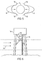
- FIG. 5 illustrates two fairings 8 that may be fixed to a cylinder 2 to form the protuberances for drag and vortex shedding reduction. These fairings 8 may be retrofitted to an existing cylinder 2.
- the fairings 8 have fasteners 10 by which they may be fixed together and to hold the fairings 8 in place upon the cylinder 2.
- the fasteners 10 could take a wide variety of forms, e.g. in one form the fastener could simply be an adhesive for sticking the fairings 8 to the cylinder 2.
- Many alternative mechanical fasteners such as straps, screws, bolts etc, could also be utilised.
- the invention could be embodied as the fairings 8 and the associated fasteners 10 to be applied to an existing elongate body, such as the cylinder 2.
- FIG. 6 illustrates one example environment in which the present invention may be used.
- a sea current 12 impinges upon an offshore platform 14.
- the sea current 12 may come from any direction making uni-directional fairings ineffective.
- the support legs 16, tension legs 18 and risers 20 are all fitted with appropriately dimensioned protuberances having differing radial directions to cope with the different directions of the sea current 12.
- the effect of the technique reduces the structural stresses upon the support legs 16 and the tension legs 18.
- the reduction in the forces on the risers 20 may mean that they can be more closely packed without risk of them banging together, which in turn means that a smaller platform 14 may be practical.
- Figure 7 illustrates another use of the invention.
- a steel chimney 22 is subject to a wind 24 that can impinge from any direction.
- Protuberances 26 are attached to the chimney 22 and reduce the wind drag and vortex induced vibrations.
- FIG 8 illustrates a further example of the use of the present invention.
- a wind turbine 28 is of the type in which the turbine blade 30 is downwind of the support tower 32 in the direction in which the turbine 30 will try to self-align.
- Wind flow disturbance produced by the support tower 32 reduces the efficiency of the turbine 30 in extracting energy from the wind flow.
- the protuberances 34 attached to the support tower 32 reduce the vortex shedding from the support tower 32 in a manner in which enables the turbine 30 to more efficiently extract energy from the wind flow.
- less wind drag is exerted on the support tower 32 which means that its construction can be less expensive.
Landscapes
- Engineering & Computer Science (AREA)
- Physics & Mathematics (AREA)
- Fluid Mechanics (AREA)
- Mechanical Engineering (AREA)
- General Engineering & Computer Science (AREA)
- Wind Motors (AREA)
- Cyclones (AREA)
- Rigid Pipes And Flexible Pipes (AREA)
- Saccharide Compounds (AREA)
- Earth Drilling (AREA)
- Gas Separation By Absorption (AREA)
- Structures Of Non-Positive Displacement Pumps (AREA)
Abstract
Description
- This invention relates to techniques for modifying fluid flow so as to reduce the effects of drag and vortex shedding. More particularly, this invention relates to such techniques that may be applied to elongate bodies.
- When an elongate body, such as a chimney, is positioned within an environment where it is subject to fluid flow, in the case of a chimney airflow, then a drag force is exerted on the elongate body and vortex shedding can occur inducing forces that can lead to undesirable vibration. The drag force of passing fluid flow often means that the elongate body has to be produced with a strengthened structure to resist such a drag force. The cost of strengthening the structure in this way can be significant. In the case of vortex shedding, the forces this exerts vary with time in a manner that can establish highly damaging undesirable vibrations within an elongate body. It may be that these vibrations will stimulate a resonance with potentially destructive consequences.
- It is known to fit fairings to structures in order to modify fluid flow around those structures to reduce drag. A problem with such fairings is that they are usually only able to cope with fluid flow from a single direction and if the fluid flow direction changes, then they may be ineffective, or in fact increase drag. The fairings may be made movable to accommodate different flow directions, but this disadvantageously increases their cost and complexity.
- It is also known to attach structures to elongate bodies in an attempt to reduce vortex shedding. An example of this is a helical strake that can be applied to the outside of a chimney. Whilst such a helical strake may reduce vortex shedding, it often has the effect of increasing drag with a disadvantageous need to increase the strength of the chimney. An alternative is the use of a perforated shroud over a chimney. Such perforated shrouds have been found to be too expensive to be practical.
- US-A-4,059,129 discloses a cylindrical body with a plurality of small planes extending from its outer surface acting as vortex generators to reduce vibrations due to transverse flow against the body.
- Discussions of vortex shedding may be found in E. Naudascher, D. Rockwell "FLOW-INDUCED VIBRATIONS an Engineering Guide", IAHR-AIRH, Hydraulic structures design manual, A. A. Balkema/Rotterdam/Brookfield/1994, 160-176 and M. M. Zdravkovich, "Review and Classification of Various Aerodynamic and Hydrodynamic Means for Suppressing Vortex Shedding," Journal of Wind Engineering and Industrial Aerodynamics, 7 (1981) 145-189.
- A description of a unidirectional fairing for use on a drilling riser to reduce vortex induced vibration is described in United States Patent US-A-6,048,136.
- Viewed from one aspect the present invention provides an elongate body having a plurality of longitudinally spaced apart smoothly curved protuberances extending therefrom, said protuberances having a surface which is smoothly curved in two orthogonal directions, said elongate body having a maximum cross-section excluding said protuberances of D, said protuberances extending from an outer surface of said elongate body excluding said protuberances by a distance within the range 0.1D to 0.75D inclusive, and said protuberances being shaped and dimensioned to modify fluid flow substantially transverse against the outside of said elongate body around said elongate body in a manner that reduces forces upon said elongate body produced by drag substantially in the flow direction and by vortex shedding substantially normal to the flow direction.
- The invention recognises and exploits the phenomenon whereby a smoothly curved protuberance (smooth at least in the sense of how it modifies the fluid flow) from an elongate body can be made to modify the fluid flow around that body in a manner that reduces the forces exerted on the body by drag and vortex shedding. The protuberance is advantageously simple and inexpensive to provide with or add to an elongate body.
- Whilst the invention could be used in situations where the fluid flow was unidirectional, in preferred embodiments of the invention said protuberances extend in a plurality of different radial directions from a longitudinal axis of said elongate body.
- This feature of the invention allows fixed protuberances that are inexpensive and simple to reduce drag and vortex shedding that can occur from fluid flow incident from any radial direction around the elongate body. This is strongly advantageous since, for example, a chimney or a drilling platform leg may be subject to fluid flow from any radial direction.
- It will be appreciated that the differences between the radial direction of adj acent protuberances may vary over a range of values. It has been found that a preferred range of values for the differences between radial directions is 30 degrees to 90 degrees inclusive. A particularly preferred arrangement that works well in many cases is when the difference in radial direction between adjacent protuberances is substantially 45 degrees.
- The protuberances could be applied to a single side of the elongate body. However, in preferred embodiments the protuberances are arranged in pairs at the same longitudinal position along the elongate body and with opposite radial directions. This has been found to be constructionally convenient and provide good omni-directional performance.
- The size of the protuberances can vary significantly depending upon the circumstances. Generally speaking, more dense fluids may require more pronounced protuberances than less dense fluids. It will also be appreciated that the protuberances should not be too large or they may result in an undesirably large increase in drag when the fluid flow is not favourably aligned with them.
- Compared with the maximum diameter D of the cross-section of the elongate body, a range of protuberance sizes has been found to be one in which the protuberances extend from an outer surface of the elongate body by a distance within the range 0.1D to 0.75D. A more preferred range is 0.25D to 0.5D.
- The longitudinal spacing of the protuberances can also vary. Placing the protuberances too close together will increase cost and weight whilst it may also reduce the effectiveness of the protuberances in modifying the fluid flow in the desired manner. Similarly, placing the protuberances too far apart will make them ineffective. In preferred embodiments of the invention the longitudinal spacing of the protuberances is such that said radial directions of said protuberances vary along said longitudinal axis in a repeating pattern with a repeat distance within the range 3D to 9D inclusive.
- It will be appreciated that the smoothly curved protuberances could have a wide variety of cross-sectional shapes. The protuberances should be smoothly curved and blend well into the shape of the rest of the elongate body so as to reduce drag. However, within this constraint, the shape may vary widely. A preferred shape that has been found to produce good results is when the cross-sectional shape of the protuberances is at least a portion of an ellipse. When the protuberances are paired together, they may be arranged in a fashion in which the back-to-back protuberances have a combined cross-sectional shape that is a full ellipse.
- The elongate body to which the protuberances are attached could similarly have a range of cross-sectional shapes, However, a circular cross-sectional shape is common in bodies that are subject to the drag and vortex shedding forces which the invention seeks to reduce and this shape has been found to benefit well from the technique of the present invention.
- The elongate body around which the fluid flow is modified by the technique of the present invention could be part of a wide variety of different structures. Examples of structures that may particularly benefit from the technique of the invention are an offshore riser, a support member of an offshore platform, a pipe, an underwater cable, chimney and a support tower for a wind turbine.
- It will be appreciated that the fluid which gives rise to the drag and vortex shedding may be either a liquid or a gas.
- The protuberances could be integrally formed with the elongate body with which they are associated. However, in preferred embodiments of the invention the protuberances may take the form of fairings (e.g. an element added to modify fluid flow) that are attached to an elongate body. The engineering of many elongate bodies is in many cases already fixed and the form of the invention as add-on fairings is particularly convenient and simple together with allowing the possibility for retrofitting.
- Viewed from another aspect the present invention provides a method of reducing fluid flow induced forces upon an elongate body produced by drag and vortex shedding said fluid flow being substantially transverse to the outside of said elongate body, the force due to drag being substantially in the flow direction and the force due to vortex shedding being substantially normal to the flow direction, said method comprising the step of providing a plurality of fluid flow modifying longitudinally spaced apart smoothly curved protuberances extending from said elongate body, said protuberances having a surface which is smoothly curved in two orthogonal directions, said elongate body having a maximum cross-section excluding said protuberances of D, said protuberances extending from an outer surface of said elongate body excluding said protuberances by a distance within the range 0.1D to 0.75D inclusive.
- Viewed from a further aspect the present invention provides a kit for modifying fluid flow around an elongate body, said kit comprising a plurality of smoothly curved fairings for fixing to said elongate body and a plurality of fairing fasteners for fixing said fairings to said elongate body to form a plurality of longitudinally spaced apart smoothly curved protuberances extending therefrom, said protuberances having a surface which is smoothly curved in two orthogonal directions, said elongate body having a maximum cross-section excluding said protuberances of D, said protuberances extending from an outer surface of said elongate body excluding said protuberances by a distance within the range 0.1D to 0.75D inclusive, and said protuberances being shaped and dimensioned to modify fluid flow substantially transverse against the outside of said elongate body around said elongate body in a manner that reduces forces upon said elongate body produced by drag substantially in the flow direction and by vortex shedding substantially normal to the flow direction.
- Supplying the fairings and associated fasteners as a kit is a likely way in which the invention may be embodied in circumstances when it is desired to retro-fit existing structures.
- Embodiments of the invention will now be described, by way of example only, with reference to the accompanying drawings in which:
- Figure 1 schematically illustrates fluid flow past a circular cross-section body with associated drag and vortex shedding;
- Figure 2 illustrates a cylindrical elongate body having flow modifying protuberances attached thereto;
- Figure 3 illustrates cross-sectional views of a pair of flow modifying protuberances;
- Figure 4 illustrates a range of protuberances sizes applied to a cylindrical body;
- Figure 5 illustrates a kit form of the protuberances; and
- Figures 6, 7 and 8 illustrate possible uses of the invention.
- Figure 1 schematically illustrates a cylindrical body 2 positioned within a fluid flow 4. The fluid flow 4 gives rise to a drag force Fdrag acting in the same direction as the fluid flow 4.
Vortices 6 are shed from alternating sides of the cylinder 2 and moved downstream within the fluid flow 4. As thesevortices 6 are shed, they subject the cylinder 2 to a varying vortex shedding force Fvortex that is of a generally periodic nature. The vortex shedding force Fvortex can vary in magnitude, direction and timing. - The drag force Fdrag can necessitate an undesirable need to increase the structural strength of the cylinder 2. The vortex shedding force Fvortex can similarly require the structure of the cylinder to be strengthened as well as raising the possibility of inducing undesirable vibrations, or even resonance, within the cylinder 2.
- Figure 2 illustrates an elongate body in the form of a cylinder to which smoothly curved protuberances have been added. These protuberances are arranged in diametrically opposed pairs with the radial direction of the protuberances varying by substantially 45 degrees between adjacent pairs of protuberances. In a test the arrangement illustrated in Figure 2 produced a 24% drag reduction compared with the plain cylinder and also led to significantly less vortex-induced vibration.
- In the specific example illustrated in Figure 2, the protuberances have an elliptical cross-section and protrude by 0.5D from the surface of the cylinder where D is the diameter of the cylinder. The protuberances are spaced at an interval of 1.75D along the length of the cylinder in an arrangement where the orientation of the protuberances repeats at a distance of 7D.
- Figure 3 schematically illustrates cross-sectional views through a pair of protuberances as illustrated in Figure 2. The end view shows the elliptical form of the protuberances. In the illustrated example, the major axis of the ellipse is W in length and the minor axis of the ellipse is D in length corresponding to the diameter of the cylinder D on which the protuberance is mounted. The plan view shows the protuberances to have a plan cross-section that is part of a circle of diameter W.
- Figure 4 illustrates three example cylinders with attached protuberance pairs of differing sizes. In each case, adjacent protuberance pairs are rotated by 45 degrees with respect to one another. The lower example shows relatively less pronounced protuberances that might be suitable for use within a less dense fluid (e.g.air) whereas the top most example shows relatively pronounced protuberances that may be more suitable for use in a more dense fluid (e.g. water).
- Figure 5 illustrates two
fairings 8 that may be fixed to a cylinder 2 to form the protuberances for drag and vortex shedding reduction. Thesefairings 8 may be retrofitted to an existing cylinder 2. Thefairings 8 havefasteners 10 by which they may be fixed together and to hold thefairings 8 in place upon the cylinder 2. Thefasteners 10 could take a wide variety of forms, e.g. in one form the fastener could simply be an adhesive for sticking thefairings 8 to the cylinder 2. Many alternative mechanical fasteners such as straps, screws, bolts etc, could also be utilised. - In the form of a kit, the invention could be embodied as the
fairings 8 and the associatedfasteners 10 to be applied to an existing elongate body, such as the cylinder 2. - Figure 6 illustrates one example environment in which the present invention may be used. A sea current 12 impinges upon an offshore platform 14. The sea current 12 may come from any direction making uni-directional fairings ineffective. The
support legs 16,tension legs 18 andrisers 20 are all fitted with appropriately dimensioned protuberances having differing radial directions to cope with the different directions of the sea current 12. The effect of the technique reduces the structural stresses upon thesupport legs 16 and thetension legs 18. The reduction in the forces on therisers 20 may mean that they can be more closely packed without risk of them banging together, which in turn means that a smaller platform 14 may be practical. - Figure 7 illustrates another use of the invention. In this example, a
steel chimney 22 is subject to awind 24 that can impinge from any direction.Protuberances 26 are attached to thechimney 22 and reduce the wind drag and vortex induced vibrations. - Figure 8 illustrates a further example of the use of the present invention. In this case a
wind turbine 28 is of the type in which theturbine blade 30 is downwind of thesupport tower 32 in the direction in which theturbine 30 will try to self-align. Wind flow disturbance produced by thesupport tower 32 reduces the efficiency of theturbine 30 in extracting energy from the wind flow. Accordingly, theprotuberances 34 attached to thesupport tower 32 reduce the vortex shedding from thesupport tower 32 in a manner in which enables theturbine 30 to more efficiently extract energy from the wind flow. Furthermore, less wind drag is exerted on thesupport tower 32 which means that its construction can be less expensive.
Claims (16)
- An elongate body (2) having a plurality of longitudinally spaced apart smoothly curved protuberances (8) extending therefrom, said protuberances having a surface which is smoothly curved in two orthogonal directions, said elongate body having a maximum cross-section excluding said protuberances of D, said protuberances extending from an outer surface of said elongate body excluding said protuberances by a distance within the range 0.1D to 0.75D inclusive, and said protuberances being shaped and dimensioned to modify fluid flow substantially transverse against the outside of said elongate body around said elongate body in a manner that reduces forces upon said elongate body produced by drag substantially in the flow direction and by vortex shedding substantially normal to the flow direction.
- An elongate body as claimed in claim 1, wherein said protuberances extend in a plurality of different radial directions from a longitudinal axis of said elongate body.
- An elongate body as claimed in claim 2, wherein longitudinally adjacent protuberances have radial directions differing by an angle within the range 30 to 90 degrees inclusive.
- An elongate body as claimed in claim 3, wherein longitudinally adjacent protuberances have radial directions differing by an angle of substantially 45 degrees.
- An elongate body as claimed in any one of the preceding claims, wherein at least two of said protuberances are arranged as a pair of protuberances having a common longitudinal position along said elongate boby and extending in opposite radial directions from said elongate body.
- An elongate body as claimed in claim 5, wherein all of said protuberances are arranged as pairs of protuberances.
- An elongate body as claimed in claim 1, wherein said protuberances extend from an outer surface of said elongate body excluding said protuberances by a distance within the range 0.25D to 0.5D inclusive.
- An elongate body as claimed in claim 3, wherein said radial directions of said protuberances vary along said longitudinal axis in a repeating pattern with a repeat distance within the range 3D to 9D inclusive.
- An elongate body as claimed in any one of the preceding claims, wherein said protuberances have a cross-sectional shape substantially corresponding to at least a portion of an ellipse.
- An elongate body as claimed in any one of the preceding claims, wherein said elongate body has a cross-sectional shape substantially corresponding to a circle.
- An elongate body as claimed in any one of the preceding claims, wherein said elongate body is one of:an offshore riser (20);a support member of an offshore platform (16);a pipean underwater cable;a chimney (22); anda support tower (32) for a wind turbine.
- An elongate body as claimed in any one of claims 1 to 10, wherein said fluid flow is liquid flow.
- An elongate body as claimed in any one of claims 1 to 10, wherein said fluid flow is gas flow.
- An elongate body as claimed in any one of the preceding claims, wherein said protuberances are formed as fairings fixed to said elongate body.
- A method of reducing fluid flow induced forces upon an elongate body produced by drag and vortex shedding said fluid flow being substantially transverse to the outside of said elongate body, the force due to drag being substantially in the flow direction and the force due to vortex shedding being substantially normal to the flow direction, said method comprising the step of providing a plurality of fluid flow modifying longitudinally spaced apart smoothly curved protuberances extending from said elongate body, said protuberances having a surface which is smoothly curved in two orthogonal directions, said elongate body having a maximum cross-section excluding said protuberances of D, said protuberances extending from an outer surface of said elongate body excluding said protuberances by a distance within the range 0.1D to 0.75D inclusive.
- A kit for modifying fluid flow around an elongate body, said kit comprising a plurality of smoothly curved fairings for fixing to said elongate body and a plurality of fairing fasteners for fixing said fairings to said elongate body to form a plurality of longitudinally spaced apart smoothly curved protuberances extending therefrom, said protuberances having a surface which is smoothly curved in two orthogonal directions, said elongate body having a maximum cross-section excluding said protuberances of D, said protuberances extending from an outer surface of said elongate body excluding said protuberances by a distance within the range 0.1D to 0.75D inclusive, and said protuberances being shaped and dimensioned to modify fluid flow substantially transverse against the outside of said elongate body around said elongate body in a manner that reduces forces upon said elongate body produced by drag substantially in the flow direction and by vortex shedding substantially normal to the flow direction.
Applications Claiming Priority (3)
| Application Number | Priority Date | Filing Date | Title |
|---|---|---|---|
| GB0013334 | 2000-06-01 | ||
| GB0013334A GB2362938A (en) | 2000-06-01 | 2000-06-01 | Reduction of vortex shedding and drag |
| PCT/GB2001/002447 WO2001092733A1 (en) | 2000-06-01 | 2001-05-31 | Vortex shedding and drag force reduction |
Publications (2)
| Publication Number | Publication Date |
|---|---|
| EP1287262A1 EP1287262A1 (en) | 2003-03-05 |
| EP1287262B1 true EP1287262B1 (en) | 2006-05-17 |
Family
ID=9892794
Family Applications (1)
| Application Number | Title | Priority Date | Filing Date |
|---|---|---|---|
| EP01934191A Expired - Lifetime EP1287262B1 (en) | 2000-06-01 | 2001-05-31 | Vortex shedding and drag force reduction |
Country Status (9)
| Country | Link |
|---|---|
| US (1) | US6908063B2 (en) |
| EP (1) | EP1287262B1 (en) |
| AT (1) | ATE326640T1 (en) |
| AU (1) | AU2001260495A1 (en) |
| DE (1) | DE60119727T2 (en) |
| DK (1) | DK1287262T3 (en) |
| ES (1) | ES2262651T3 (en) |
| GB (1) | GB2362938A (en) |
| WO (1) | WO2001092733A1 (en) |
Cited By (1)
| Publication number | Priority date | Publication date | Assignee | Title |
|---|---|---|---|---|
| WO2020057706A1 (en) * | 2018-09-19 | 2020-03-26 | Envision Energy (Denmark) Aps | Wind turbine having a circular or conical tower structure with passive flow control means and use of such circular tower structure |
Families Citing this family (25)
| Publication number | Priority date | Publication date | Assignee | Title |
|---|---|---|---|---|
| DE10301080A1 (en) * | 2002-10-22 | 2004-05-13 | Siemens Ag | Wind turbine |
| US20090114001A1 (en) * | 2007-05-25 | 2009-05-07 | Bernitsas Michael M | Enhancement of vortex induced forces and motion through surface roughness control |
| US20070018055A1 (en) | 2005-07-11 | 2007-01-25 | Schmidt Eric T | Aerodynamically efficient surface |
| EP1921329A1 (en) * | 2005-08-04 | 2008-05-14 | Federal State Unitary Enterprise "Central Aerohydrodynamic Institute named by Prof. N.E. Zhukovsky", TSAGI | Aerodynamic noise reducing method (variants) and low-noise structural element for operating in a fluid medium flow |
| FR2895901B1 (en) * | 2006-01-11 | 2008-04-18 | Ass Rene Leriche Ass Loi De 19 | ARTERIAL ENDOPROTHESIS |
| US8523492B2 (en) * | 2007-01-05 | 2013-09-03 | Benton Frederick Baugh | Method of installing fairings around vertical pipes |
| US8684040B2 (en) * | 2007-05-25 | 2014-04-01 | The Regents Of The University Of Michigan | Reduction of vortex induced forces and motion through surface roughness control |
| US20080302537A1 (en) * | 2007-06-07 | 2008-12-11 | Mcmiles Barry James | Dimpled riser floatation module |
| US8579546B2 (en) * | 2008-01-18 | 2013-11-12 | VIV Supression, Inc. | Apparatus and method for inhibiting vortex-induced vibration |
| GB2462602B (en) | 2008-08-11 | 2012-09-19 | Statoilhydro Asa | Method and apparatus for towing offshore wind turbines |
| CN103423098A (en) * | 2012-05-17 | 2013-12-04 | 华锐风电科技(集团)股份有限公司 | Tower drum and wind generating set |
| TWM448412U (en) * | 2012-11-14 | 2013-03-11 | Chen-Quan Hu | Current guiding structure |
| CN103321593B (en) * | 2013-06-25 | 2015-02-04 | 西南石油大学 | Device and method for actively eliminating vortex-induced vibration of stand pipe |
| DK3085956T3 (en) | 2015-04-21 | 2018-02-26 | Nordex Energy Gmbh | Tower for a wind power plant as well as methods for erecting a wind power plant |
| EP3184980B1 (en) | 2015-12-21 | 2019-04-03 | ENDRESS + HAUSER WETZER GmbH + Co. KG | Temperature sensor for measuring the temperature of a medium in a vessel or a pipe |
| EP3565967B1 (en) * | 2017-02-15 | 2021-03-17 | Siemens Gamesa Renewable Energy A/S | Building structure comprising a vortex generator to reduce induced vibrations |
| CN107461302B (en) | 2017-09-11 | 2018-10-02 | 北京金风科创风电设备有限公司 | Envelope structure with external surface having function of inhibiting vortex excitation vibration |
| DK3698006T3 (en) * | 2017-10-20 | 2022-10-31 | Balmoral Comtec Ltd | A cylindrical element profiled to reduce vortex induced vibration (VIV) and/or drag |
| EP3553482A1 (en) | 2018-04-10 | 2019-10-16 | Endress+Hauser Wetzer GmbH+CO. KG | Thermowell with reduced sensitivity to vortex induced vibrations |
| US10900296B2 (en) * | 2018-04-11 | 2021-01-26 | CBM International, Inc. | Methods and systems for VIV suppression utilizing retractable fins |
| CN108799010B (en) * | 2018-06-21 | 2020-10-09 | 北京金风科创风电设备有限公司 | Enclosure with mixing absorber on outer surface |
| CN110671059A (en) * | 2019-09-09 | 2020-01-10 | 建湖县永维阀门钻件有限公司 | Device for restraining vortex-induced vibration of marine drilling riser and preparation method thereof |
| EP4056974B1 (en) | 2021-03-08 | 2024-05-22 | Endress+Hauser Wetzer GmbH+CO. KG | Measuring apparatus with thermowell with reduced sensitivity to vortex induced vibrations |
| EP4095500A1 (en) | 2021-05-28 | 2022-11-30 | Endress+Hauser Wetzer GmbH+CO. KG | Thermometer with vibration detection |
| EP4321749A1 (en) * | 2022-08-12 | 2024-02-14 | Wobben Properties GmbH | Wind power plant and vortex generator therefor |
Family Cites Families (13)
| Publication number | Priority date | Publication date | Assignee | Title |
|---|---|---|---|---|
| GB244520A (en) * | 1924-09-17 | 1925-12-17 | Samuel Edgar Saunders | Improvements in or relating to flying and other boats or vessels |
| US3463418A (en) * | 1968-03-20 | 1969-08-26 | Edmond S Miksch | Vortex generator for airplane wing |
| US3578264A (en) * | 1968-07-09 | 1971-05-11 | Battelle Development Corp | Boundary layer control of flow separation and heat exchange |
| NL7501866A (en) * | 1975-02-18 | 1976-08-20 | Tno | CYLINDER-SHAPED BODY PROVIDED WITH MEANS TO AVOID VIBRATIONS DUE TO CROSS FLOW THROUGH A FLUIDUM. |
| GB2162610B (en) * | 1984-08-02 | 1987-12-16 | Thomas Henderson | Regulation of response of bodies to a fluid flow |
| US5114099A (en) * | 1990-06-04 | 1992-05-19 | W. L. Chow | Surface for low drag in turbulent flow |
| WO1994002744A1 (en) * | 1991-07-18 | 1994-02-03 | Velke Willi H | A device to reduce drag over the surface of mast and boom of a sailcraft |
| US5205519A (en) * | 1992-01-07 | 1993-04-27 | The United States Of America As Represented By The United States National Aeronautics And Space Administration | Boundary layer relaminarization device |
| DE9316009U1 (en) * | 1993-10-20 | 1994-01-13 | Moser, Josef, 85435 Erding | Surface of a fluid-flowed body |
| US5803409A (en) * | 1996-06-06 | 1998-09-08 | Nielsen Engineering & Research, Inc. | Method and apparatus for reducing the drag of flows over surfaces |
| US6048136A (en) | 1996-07-19 | 2000-04-11 | Shell Oil Company | Vortex induced vibration protection for deepwater drilling risers |
| US5988568A (en) * | 1997-09-22 | 1999-11-23 | Drews; Hilbert F. P. | Surface modification apparatus and method for decreasing the drag or retarding forces created by fluids flowing across a moving surface |
| GB2378493B (en) * | 1998-03-07 | 2003-04-09 | Crp Group Ltd | Protection of underwater elongate members |
-
2000
- 2000-06-01 GB GB0013334A patent/GB2362938A/en not_active Withdrawn
-
2001
- 2001-05-31 AT AT01934191T patent/ATE326640T1/en not_active IP Right Cessation
- 2001-05-31 DE DE60119727T patent/DE60119727T2/en not_active Expired - Fee Related
- 2001-05-31 US US10/296,969 patent/US6908063B2/en not_active Expired - Fee Related
- 2001-05-31 DK DK01934191T patent/DK1287262T3/en active
- 2001-05-31 AU AU2001260495A patent/AU2001260495A1/en not_active Abandoned
- 2001-05-31 WO PCT/GB2001/002447 patent/WO2001092733A1/en not_active Ceased
- 2001-05-31 EP EP01934191A patent/EP1287262B1/en not_active Expired - Lifetime
- 2001-05-31 ES ES01934191T patent/ES2262651T3/en not_active Expired - Lifetime
Cited By (1)
| Publication number | Priority date | Publication date | Assignee | Title |
|---|---|---|---|---|
| WO2020057706A1 (en) * | 2018-09-19 | 2020-03-26 | Envision Energy (Denmark) Aps | Wind turbine having a circular or conical tower structure with passive flow control means and use of such circular tower structure |
Also Published As
| Publication number | Publication date |
|---|---|
| ATE326640T1 (en) | 2006-06-15 |
| WO2001092733A1 (en) | 2001-12-06 |
| DE60119727T2 (en) | 2007-01-04 |
| ES2262651T3 (en) | 2006-12-01 |
| EP1287262A1 (en) | 2003-03-05 |
| US20040051004A1 (en) | 2004-03-18 |
| GB2362938A (en) | 2001-12-05 |
| DE60119727D1 (en) | 2006-06-22 |
| AU2001260495A1 (en) | 2001-12-11 |
| US6908063B2 (en) | 2005-06-21 |
| DK1287262T3 (en) | 2006-06-12 |
| GB0013334D0 (en) | 2000-07-26 |
Similar Documents
| Publication | Publication Date | Title |
|---|---|---|
| EP1287262A1 (en) | Vortex shedding and drag force reduction | |
| Kumar et al. | Passive control of vortex-induced vibrations: an overview | |
| US5410979A (en) | Small fixed teardrop fairings for vortex induced vibration suppression | |
| Zdravkovich | Review and classification of various aerodynamic and hydrodynamic means for suppressing vortex shedding | |
| EP2049805B1 (en) | Twin fin fairing | |
| US20070215028A1 (en) | Fairing for reducing watercurrent-induced stresses on a marine riser | |
| US9725961B2 (en) | Fairing | |
| US6619887B1 (en) | Method and apparatus for reducing drag and suppressing vortex-induced vibration | |
| KR102616097B1 (en) | Apparatus for reducing vortex induced vibration | |
| CN110145254A (en) | A standpipe vortex-induced vibration suppression device | |
| CN108194035B (en) | Device and method for suppressing vortex-induced vibration of marine riser | |
| KR102455878B1 (en) | Vortex induced vibration reducing apparatus | |
| EP3314082B1 (en) | A cylindrical element adapted to reduce vortex-induced vibration and/or drag | |
| US10400518B2 (en) | Paired helically indented methods and systems for VIV suppression of drilling riser buoyancy module for fluid submerged cylinders | |
| EP3314083B1 (en) | A flow modification device, system, and method | |
| US20060054073A1 (en) | Apparatus and method for reducing vortices in the wake of a marine member | |
| CN108301325B (en) | Non-uniform surface wind-resistant cable | |
| AU2020101950A4 (en) | A method to protect marine drilling riser from vortex-induced vibration | |
| EP3393900B1 (en) | A flow modification device having helical strakes and a system and method for modifying flow | |
| AU2007323831B2 (en) | Systems and methods for reducing drag and/or vortex induced vibration | |
| CN116398511A (en) | A vortex-induced vibration suppression device | |
| Gonçalves et al. | Experimental Study on Flow-Induced Motions of Floating Square Cylinders with Twisted Surfaces | |
| WO2009046166A1 (en) | Systems and methods for reducing drag and/or vortex induced vibration | |
| KR20190091955A (en) | Vortex induced vibration reduction device of offshore structure | |
| BR112018069175B1 (en) | FLOW MODIFICATION DEVICE AND SYSTEM AND METHOD FOR REDUCING VIBRATION |
Legal Events
| Date | Code | Title | Description |
|---|---|---|---|
| PUAI | Public reference made under article 153(3) epc to a published international application that has entered the european phase |
Free format text: ORIGINAL CODE: 0009012 |
|
| 17P | Request for examination filed |
Effective date: 20021204 |
|
| AK | Designated contracting states |
Kind code of ref document: A1 Designated state(s): AT BE CH CY DE DK ES FI FR GB GR IE IT LI LU MC NL PT SE TR |
|
| AX | Request for extension of the european patent |
Extension state: AL LT LV MK RO SI |
|
| 17Q | First examination report despatched |
Effective date: 20041229 |
|
| GRAP | Despatch of communication of intention to grant a patent |
Free format text: ORIGINAL CODE: EPIDOSNIGR1 |
|
| GRAS | Grant fee paid |
Free format text: ORIGINAL CODE: EPIDOSNIGR3 |
|
| GRAA | (expected) grant |
Free format text: ORIGINAL CODE: 0009210 |
|
| RAP1 | Party data changed (applicant data changed or rights of an application transferred) |
Owner name: IMPERIAL COLLEGE INNOVATIONS LIMITED |
|
| RAP1 | Party data changed (applicant data changed or rights of an application transferred) |
Owner name: IMPERIAL INNOVATIONS LIMITED |
|
| AK | Designated contracting states |
Kind code of ref document: B1 Designated state(s): AT BE CH CY DE DK ES FI FR GB GR IE IT LI LU MC NL PT SE TR |
|
| PG25 | Lapsed in a contracting state [announced via postgrant information from national office to epo] |
Ref country code: CH Free format text: LAPSE BECAUSE OF FAILURE TO SUBMIT A TRANSLATION OF THE DESCRIPTION OR TO PAY THE FEE WITHIN THE PRESCRIBED TIME-LIMIT Effective date: 20060517 Ref country code: FI Free format text: LAPSE BECAUSE OF FAILURE TO SUBMIT A TRANSLATION OF THE DESCRIPTION OR TO PAY THE FEE WITHIN THE PRESCRIBED TIME-LIMIT Effective date: 20060517 Ref country code: AT Free format text: LAPSE BECAUSE OF FAILURE TO SUBMIT A TRANSLATION OF THE DESCRIPTION OR TO PAY THE FEE WITHIN THE PRESCRIBED TIME-LIMIT Effective date: 20060517 Ref country code: BE Free format text: LAPSE BECAUSE OF FAILURE TO SUBMIT A TRANSLATION OF THE DESCRIPTION OR TO PAY THE FEE WITHIN THE PRESCRIBED TIME-LIMIT Effective date: 20060517 Ref country code: LI Free format text: LAPSE BECAUSE OF FAILURE TO SUBMIT A TRANSLATION OF THE DESCRIPTION OR TO PAY THE FEE WITHIN THE PRESCRIBED TIME-LIMIT Effective date: 20060517 |
|
| REG | Reference to a national code |
Ref country code: GB Ref legal event code: FG4D |
|
| PG25 | Lapsed in a contracting state [announced via postgrant information from national office to epo] |
Ref country code: IE Free format text: LAPSE BECAUSE OF NON-PAYMENT OF DUE FEES Effective date: 20060531 Ref country code: MC Free format text: LAPSE BECAUSE OF NON-PAYMENT OF DUE FEES Effective date: 20060531 |
|
| REG | Reference to a national code |
Ref country code: CH Ref legal event code: EP |
|
| REG | Reference to a national code |
Ref country code: DK Ref legal event code: T3 |
|
| REG | Reference to a national code |
Ref country code: IE Ref legal event code: FG4D |
|
| REF | Corresponds to: |
Ref document number: 60119727 Country of ref document: DE Date of ref document: 20060622 Kind code of ref document: P |
|
| PG25 | Lapsed in a contracting state [announced via postgrant information from national office to epo] |
Ref country code: SE Free format text: LAPSE BECAUSE OF FAILURE TO SUBMIT A TRANSLATION OF THE DESCRIPTION OR TO PAY THE FEE WITHIN THE PRESCRIBED TIME-LIMIT Effective date: 20060817 |
|
| PG25 | Lapsed in a contracting state [announced via postgrant information from national office to epo] |
Ref country code: PT Free format text: LAPSE BECAUSE OF FAILURE TO SUBMIT A TRANSLATION OF THE DESCRIPTION OR TO PAY THE FEE WITHIN THE PRESCRIBED TIME-LIMIT Effective date: 20061017 |
|
| ET | Fr: translation filed | ||
| REG | Reference to a national code |
Ref country code: CH Ref legal event code: PL |
|
| REG | Reference to a national code |
Ref country code: ES Ref legal event code: FG2A Ref document number: 2262651 Country of ref document: ES Kind code of ref document: T3 |
|
| PLBE | No opposition filed within time limit |
Free format text: ORIGINAL CODE: 0009261 |
|
| STAA | Information on the status of an ep patent application or granted ep patent |
Free format text: STATUS: NO OPPOSITION FILED WITHIN TIME LIMIT |
|
| 26N | No opposition filed |
Effective date: 20070220 |
|
| PG25 | Lapsed in a contracting state [announced via postgrant information from national office to epo] |
Ref country code: GR Free format text: LAPSE BECAUSE OF FAILURE TO SUBMIT A TRANSLATION OF THE DESCRIPTION OR TO PAY THE FEE WITHIN THE PRESCRIBED TIME-LIMIT Effective date: 20060818 |
|
| PG25 | Lapsed in a contracting state [announced via postgrant information from national office to epo] |
Ref country code: LU Free format text: LAPSE BECAUSE OF NON-PAYMENT OF DUE FEES Effective date: 20060531 Ref country code: TR Free format text: LAPSE BECAUSE OF FAILURE TO SUBMIT A TRANSLATION OF THE DESCRIPTION OR TO PAY THE FEE WITHIN THE PRESCRIBED TIME-LIMIT Effective date: 20060517 |
|
| PGFP | Annual fee paid to national office [announced via postgrant information from national office to epo] |
Ref country code: DE Payment date: 20080605 Year of fee payment: 8 Ref country code: DK Payment date: 20080515 Year of fee payment: 8 Ref country code: ES Payment date: 20080619 Year of fee payment: 8 |
|
| PGFP | Annual fee paid to national office [announced via postgrant information from national office to epo] |
Ref country code: IT Payment date: 20080527 Year of fee payment: 8 |
|
| PGFP | Annual fee paid to national office [announced via postgrant information from national office to epo] |
Ref country code: NL Payment date: 20080501 Year of fee payment: 8 |
|
| PG25 | Lapsed in a contracting state [announced via postgrant information from national office to epo] |
Ref country code: CY Free format text: LAPSE BECAUSE OF FAILURE TO SUBMIT A TRANSLATION OF THE DESCRIPTION OR TO PAY THE FEE WITHIN THE PRESCRIBED TIME-LIMIT Effective date: 20060517 |
|
| PGFP | Annual fee paid to national office [announced via postgrant information from national office to epo] |
Ref country code: GB Payment date: 20080604 Year of fee payment: 8 |
|
| REG | Reference to a national code |
Ref country code: DK Ref legal event code: EBP |
|
| GBPC | Gb: european patent ceased through non-payment of renewal fee |
Effective date: 20090531 |
|
| NLV4 | Nl: lapsed or anulled due to non-payment of the annual fee |
Effective date: 20091201 |
|
| PG25 | Lapsed in a contracting state [announced via postgrant information from national office to epo] |
Ref country code: NL Free format text: LAPSE BECAUSE OF NON-PAYMENT OF DUE FEES Effective date: 20091201 |
|
| REG | Reference to a national code |
Ref country code: FR Ref legal event code: ST Effective date: 20100129 |
|
| PG25 | Lapsed in a contracting state [announced via postgrant information from national office to epo] |
Ref country code: FR Free format text: LAPSE BECAUSE OF NON-PAYMENT OF DUE FEES Effective date: 20090602 Ref country code: DK Free format text: LAPSE BECAUSE OF NON-PAYMENT OF DUE FEES Effective date: 20090531 |
|
| PGFP | Annual fee paid to national office [announced via postgrant information from national office to epo] |
Ref country code: FR Payment date: 20080514 Year of fee payment: 8 |
|
| PG25 | Lapsed in a contracting state [announced via postgrant information from national office to epo] |
Ref country code: GB Free format text: LAPSE BECAUSE OF NON-PAYMENT OF DUE FEES Effective date: 20090531 |
|
| PG25 | Lapsed in a contracting state [announced via postgrant information from national office to epo] |
Ref country code: DE Free format text: LAPSE BECAUSE OF NON-PAYMENT OF DUE FEES Effective date: 20091201 |
|
| REG | Reference to a national code |
Ref country code: ES Ref legal event code: FD2A Effective date: 20090601 |
|
| PG25 | Lapsed in a contracting state [announced via postgrant information from national office to epo] |
Ref country code: ES Free format text: LAPSE BECAUSE OF NON-PAYMENT OF DUE FEES Effective date: 20090601 |
|
| PG25 | Lapsed in a contracting state [announced via postgrant information from national office to epo] |
Ref country code: IT Free format text: LAPSE BECAUSE OF NON-PAYMENT OF DUE FEES Effective date: 20090531 |