EP1286497B1 - Method for graphically representing the status of network elements of a monitored network, and corresponding monitoring system and program module - Google Patents
Method for graphically representing the status of network elements of a monitored network, and corresponding monitoring system and program module Download PDFInfo
- Publication number
- EP1286497B1 EP1286497B1 EP01440243A EP01440243A EP1286497B1 EP 1286497 B1 EP1286497 B1 EP 1286497B1 EP 01440243 A EP01440243 A EP 01440243A EP 01440243 A EP01440243 A EP 01440243A EP 1286497 B1 EP1286497 B1 EP 1286497B1
- Authority
- EP
- European Patent Office
- Prior art keywords
- network
- reports
- network element
- trend
- network elements
- Prior art date
- Legal status (The legal status is an assumption and is not a legal conclusion. Google has not performed a legal analysis and makes no representation as to the accuracy of the status listed.)
- Expired - Lifetime
Links
Images
Classifications
-
- H—ELECTRICITY
- H04—ELECTRIC COMMUNICATION TECHNIQUE
- H04L—TRANSMISSION OF DIGITAL INFORMATION, e.g. TELEGRAPHIC COMMUNICATION
- H04L41/00—Arrangements for maintenance, administration or management of data switching networks, e.g. of packet switching networks
- H04L41/22—Arrangements for maintenance, administration or management of data switching networks, e.g. of packet switching networks comprising specially adapted graphical user interfaces [GUI]
-
- H—ELECTRICITY
- H04—ELECTRIC COMMUNICATION TECHNIQUE
- H04L—TRANSMISSION OF DIGITAL INFORMATION, e.g. TELEGRAPHIC COMMUNICATION
- H04L41/00—Arrangements for maintenance, administration or management of data switching networks, e.g. of packet switching networks
- H04L41/06—Management of faults, events, alarms or notifications
- H04L41/0604—Management of faults, events, alarms or notifications using filtering, e.g. reduction of information by using priority, element types, position or time
- H04L41/0609—Management of faults, events, alarms or notifications using filtering, e.g. reduction of information by using priority, element types, position or time based on severity or priority
-
- H—ELECTRICITY
- H04—ELECTRIC COMMUNICATION TECHNIQUE
- H04L—TRANSMISSION OF DIGITAL INFORMATION, e.g. TELEGRAPHIC COMMUNICATION
- H04L41/00—Arrangements for maintenance, administration or management of data switching networks, e.g. of packet switching networks
- H04L41/06—Management of faults, events, alarms or notifications
- H04L41/0604—Management of faults, events, alarms or notifications using filtering, e.g. reduction of information by using priority, element types, position or time
- H04L41/0622—Management of faults, events, alarms or notifications using filtering, e.g. reduction of information by using priority, element types, position or time based on time
-
- H—ELECTRICITY
- H04—ELECTRIC COMMUNICATION TECHNIQUE
- H04Q—SELECTING
- H04Q3/00—Selecting arrangements
- H04Q3/0016—Arrangements providing connection between exchanges
- H04Q3/0062—Provisions for network management
Definitions
- the invention relates to a method for the visual representation of states of network elements of a network to be monitored in one Monitoring device according to the preamble of claim 1, and a monitoring device and program module for this.
- Alarm management For monitoring and controlling a communication network with a A large number of network elements are now central monitoring procedures used with standardized messages. An essential part of this Monitoring procedures concern alarm management. To the Alarm management is part of the collection of all alarm messages Objects of the monitored network or subnetwork, the determination of Alarm conditions and the visual representation of the messages and Alarm conditions.
- the alarm messages and are from the International Telecommunication Unit (ITU) entitled Recommendation X.733 "Information Technology - Open System Interconnection - System Management: Alarm Reporting Function "standardized, in the following briefly ITU guideline X.733 called.
- ITU International Telecommunication Unit
- Alarm types, Alarm causes, alarm severity levels or Urgency levels and various alarm displays, for example a trend display and a threshold value display (English: threshold information) defined. To display the trend, it is determined whether the urgency of a currently detected alarm is higher or lower is the urgency of all alarms that have been determined (and still current) so far.
- a communication network is monitored depending on its size this network from one or more central monitoring stations. Efficient monitoring with the lowest possible personnel expenditure requires the monitoring device to be concentrated as much as possible few monitoring points. This means that a monitoring body for monitoring a variety of network devices, for example is responsible for more than 50 exchanges.
- the efficiency a surveillance agency depends to a large extent on the User interface, i.e. the visual representation of alarm messages and alarm states and the trend display of alarm states.
- Network elements are represented by connecting lines. Due to the complex network of relationships, only a very limited one Number of network elements can be displayed in one screen window. In order to be able to represent each of these network elements when required, this is Network divided into several sub-networks or sub-graphics, one in upper display level, these subnetworks each as an image object are displayed and only when you select or click on one Picture element a corresponding sub-graphic with the contained therein Network elements is shown.
- Another window shows, for example, in a scrollable (to scroll) List all incoming alarm messages in their chronological order.
- the alarm messages received can also be checked filter certain criteria. For example, it is possible only To display alarm messages from a certain severity.
- the operator must monitor the alarm status of the network elements frequently switch between the views described above. to Assessment of the dynamic development of alarm conditions, i.e. to Trend forecast, it is also necessary to update current alarm numbers with earlier compare the number of alarms shown.
- US 6,112,015 discloses this a method in which network objects of a network as so-called Icons are displayed on a screen. Different states or status information of these network objects can in each case by certain presentation methods or attributes of these icons (e.g. by a dashed, bold or three-dimensional modeled border) being represented.
- the invention has for its object a method for compact Representation of a network and its dynamic development from Alarm conditions and the means necessary for its execution create.
- this object is achieved by a method according to the teaching of claim 1, a monitoring device according to the teaching of Claim 7 and a program module according to the teaching of claim 8 solved.
- the basic idea of the invention is based on incoming messages Network element or for a network element a current state from a Set of possible states for the network elements of a monitored Network to determine the number of pending messages a Determine network element at certain times, and a to determine current state trend, all network elements or selected Represent network elements as image objects on a screen, where each image object at least that for the corresponding network element shows the determined current status and status trend.
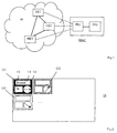
- FIG. 1 shows a communication network N with three interconnected Network elements NE1, NE2 and NE3 and a network monitoring device NMC, which a processing unit PRU and an associated Representation unit DIU.
- the network elements NE1, NE2 and NE3 are each represented by dashed lines with the Processing unit PRU connected. These dashed lines symbolize a management network or Administrative connections through which alarm messages and messages the network elements NE1, NE2 and NE3 to the network monitoring device NMC are transmitted.
- the network elements NE1, NE2 and NE3 represent communication nodes of the Communication network N, in particular switching centers.
- the ITU guideline X.733 mentioned above defines this for everyone Alarm message including the parameters event time, event type and Event information.
- the event time is the time of the alarm occurrence or the Alarm generation in the network element.
- the event type categorizes the alarm occurred. It can be, for example Communication alarm, a quality of service alarm Service), device error alarm, processing error alarm or Act environmental alarm.
- the event information includes a detailed predefined information about the possible cause of the Alarm. Possible causes of a communication alarm can be for example, a call establishment error error) or a loss of signal. to Event information also includes urgency information. Doing so evaluates how big the effects on the respective network element are.
- Monitoring device NMC received alarm messages in different forms and, if necessary, by means of hierarchical Display levels as a (screen) window on a screen visualized on the display unit DIU.
- a window with a network graphic for an overview is offered, in which the individual network elements NE1, NE2 and NE3 of the to be monitored Communication network N as small picture objects or so-called "icons" being represented.
- the picture objects have a name, for example Symbol for the type of network element, a numeric Display of incoming pending alarms and depending on the current one Urgency, i.e. after the most urgent alarm still pending can take defined alarm colors.
- the relationships of Network elements are represented by connecting lines.
- Another window shows, for example, in a scrollable (to scroll) List all incoming alarm messages in their chronological order on.
- the alarm messages received can be displayed filtered by the operator according to different defined criteria. That's the way it is for example possible, only alarm messages from a certain one Display severity or certain alarm messages only then display when a certain number of similar alarm messages has been received.
- Such alarm messages can also optionally be used suppressed which have already been completed, i.e. which by the operator were acknowledged as done or for which in the corresponding network element it was determined that the cause of the alarm no longer exists and a corresponding alarm message in the monitoring device NMC received.
- the ITU guideline X.733 defined above a trend indication for the development of the Urgency of alarms.
- many network elements represent complex ones Devices with multiple sub-elements or objects, where each of these objects sends out alarm messages independently. Since the Determination of the trend display mentioned in the network element NE1, NE2 or NE3 takes place and as a parameter to the network monitoring device NMC such a trend display can therefore only ever be transmitted get the respective object.
- the Trend display takes three possible states: depending on whether the highest reported urgency level of a current time interval compared to the highest level of urgency reported earlier interval is higher, equal or lower, the Trend display the status "increasing urgency", "no change” or "decreasing urgency”.
- this trend display has the disadvantage that it makes no statement about contains the trend of the number of pending pending alarm messages and only on an object of a network element NE1, NE2 or NE3 refers.
- NE1, NE2 or NE3 refers.
- Often all incoming alarm messages indicate an object the same level of urgency. For example, an object becomes a Exchange, which is close to its capacity limit, increased Report alarm messages about failed connection attempts. With increasing utilization of the exchange come in increasingly Similar messages of shorter intervals.
- the state of the art according to such alarm messages solve, despite increasing frequency a neutral trend display.
- a state trend is formed which shows how the number of pending alarm messages and thus the status of one Network element NE1, NE2 or NE3 developed.
- a Status trend only for alarm messages with certain criteria, for example for pending alarm messages for a specific Urgency level or from a certain urgency level.
- On unfinished alarm message is an alarm message whose the cause of the alarm has not yet been remedied and therefore not yet Completion notification, i.e. one complementary to the alarm message Message that has been received.
- the completion message can be from corresponding network element NE1, NE2 or NE3 come or through Input of the operating personnel in the network monitoring device NMC (not all network elements can carry out notification themselves initiate). It is also conceivable that if there is no completion report the completion of an alarm after a certain period of time Is accepted.
- Time intervals This is done at certain times, preferably in the same length Time intervals, entered in the network monitoring device and alarms not yet resolved.
- This length of the time intervals can be predefined or configurable. In the simplest case, it shows State trend 3 states on: increasing number, constant number and decreasing number. Alternatively, the state trend can be more than three Accept values, for example between a slight increase and sharp increase or slight decrease and sharp decrease further is distinguished.
- FIG. 2 shows a screen surface or image display DI on a Screen of the display unit DIU of an inventive Monitoring device with three image objects O1, O2 and O3, which the network elements NE1, NE2 and NE3 of Represent communication network N from Fig.1.
- the picture objects are in Formed a tightly packed matrix.
- Each picture object shows a certain color, here hatched as black, white or black symbolizes, and three display fields 11, 12 and 13.
- the first Display field 11 labeled NAME provides a name field Identification of the respective network element.
- the second display field 12 with the inscription N represents a number field. In this number field you can for example the sum of all current or not completed critical or urgent alarm messages of the respective network element are displayed.
- the third display field shows an arrow in a circle, which is a trend depending on the direction.
- the exemplary in The first image object O1 horizontally represented arrow represents a neutral one Trend for the first network element NE1
- the example in the second Image object O2 from bottom left to top right represents an arrow positive trend for the second network element NE2
- the example in the third image object O3 from top left to bottom right arrow represents a negative trend.
- one image object O1, O2 or O3 exactly one network element NE1, NE2 or NE3, for example one Switching center, a so-called gateway, a so-called router or represents a service computer.
- network elements for example the network elements of one regional subnet can be represented as an image object.
- the color of this The picture object then corresponds to the color of each of its network elements, which one has the most critical condition.
- the state trend then shows the trend exactly the sum of the alarms and thus the overall condition of all affected network elements.
- the method according to the invention allows due to the dense arrangement of network elements NE1, NE2 and NE3, each with integrated Trend state a highly compressed and at the same time meaningful information about states and dynamic Condition development of an extensive network. An operator can thus largely dispense with other images as long as it is in Development discovered no abnormalities here. Only when, for example a network element in a critical state also a positive one Trend condition, the operator needs to get more detailed Information on a view with complete alarm messages about this Change network element.
- the display can be set to selected network elements are restricted according to certain criteria. So can be defined as a selection criterion, for example, that only Elements from a certain urgency level and with neutral or positive status trend are displayed.
- the content of at least one current message especially the content of the last message received, one Network element NE1, NE2 or NE3 displayed on request.
- This Information can also be in a speech bubble Message windows (a so-called "bubble aid") appear when the screen cursor is moved to a corresponding image object.
- a summary trend information of each Network elements NE1, NE2 and NE3 represents a detailed Trend information, e.g. the number of alarms per severity, the number new / deleted alarms in the last interval or the status trend each Object of a network element, displayed on the DI screen when requested become.
- the request can be just as in the previous sections for a (detailed) representation of messages described by means of a Message window take place.
Abstract
Description
Die Erfindung betrifft ein Verfahren zur visuellen Darstellung von Zuständen von Netzelementen eines zu überwachenden Netzwerks in einer Überwachungseinrichtung nach dem Oberbegriff des Anspruch 1, sowie eine Überwachungseinrichtung und Programmmodul hierfür.The invention relates to a method for the visual representation of states of network elements of a network to be monitored in one Monitoring device according to the preamble of claim 1, and a monitoring device and program module for this.
Zur Überwachung und Steuerung eines Kommunikationsnetzes mit einer Vielzahl von Netzelementen werden heute zentrale Überwachungsverfahren mit standardisierten Meldungen eingesetzt. Einen wesentlichen Teil dieser Überwachungsverfahren betrifft die Alarmverwaltung. Zu der Alarmverwaltung gehört die Sammlung aller Alarmmeldungen von Objekten des überwachten Netzes oder Teilnetzes, die Ermittlung von Alarmzuständen und die visuelle Darstellung der Meldungen und Alarmzustände. Die Alarmmeldungen und sind von der International Telecommunication Unit (ITU) als Recommendation X.733 mit dem Titel "Information Technology - Open System Interconnection - System Management: Alarm Reporting Function" normiert, im folgenden kurz ITU-Richtlinie X.733 genannt. Dabei werden insbesondere Alarmtypen, Alarmursachen, Alarm-Schweregrade (engl.: alarm severity levels) oder Dringlichkeitsstufen und verschiedene Alarmdarstellungen, beispielsweise eine Trendanzeige (engl.: trend indication) und eine Schwellwertanzeige (engl.: threshold information) definiert. Zur Trendanzeige wird ermittelt, ob die Dringlichkeit eines aktuell ermittelten Alarms höher gleich oder geringer ist, als die Dringlichkeit aller bisher ermittelten (und noch aktuellen) Alarme.For monitoring and controlling a communication network with a A large number of network elements are now central monitoring procedures used with standardized messages. An essential part of this Monitoring procedures concern alarm management. To the Alarm management is part of the collection of all alarm messages Objects of the monitored network or subnetwork, the determination of Alarm conditions and the visual representation of the messages and Alarm conditions. The alarm messages and are from the International Telecommunication Unit (ITU) entitled Recommendation X.733 "Information Technology - Open System Interconnection - System Management: Alarm Reporting Function "standardized, in the following briefly ITU guideline X.733 called. In particular, alarm types, Alarm causes, alarm severity levels or Urgency levels and various alarm displays, for example a trend display and a threshold value display (English: threshold information) defined. To display the trend, it is determined whether the urgency of a currently detected alarm is higher or lower is the urgency of all alarms that have been determined (and still current) so far.
Die Überwachung eines Kommunikationsnetzes erfolgt je nach Größe dieses Netzes von einer oder mehreren zentralen Überwachungsstellen aus. Eine effiziente Überwachung mit möglichst geringem Personalaufwand erfordert die Konzentration der Überwachungseinrichtung auf möglichst wenige Überwachungsstellen. Dies bedeutet, dass eine Überwachungsstelle für die Überwachung einer Vielzahl von Netzeinrichtungen, beispielsweise für mehr als 50 Vermittlungsstellen zuständig ist. Die Leistungsfähigkeit einer Überwachungsstelle hängt in hohem Maße von der Benutzeroberfläche, d.h. der visuellen Darstellung von Alarmmeldungen und Alarmzuständen und der Trendanzeige von Alarmzuständen ab.A communication network is monitored depending on its size this network from one or more central monitoring stations. Efficient monitoring with the lowest possible personnel expenditure requires the monitoring device to be concentrated as much as possible few monitoring points. This means that a monitoring body for monitoring a variety of network devices, for example is responsible for more than 50 exchanges. The efficiency a surveillance agency depends to a large extent on the User interface, i.e. the visual representation of alarm messages and alarm states and the trend display of alarm states.
Ein wesentliches Problem der visuellen Darstellung der Überwachungseinrichtungen heutiger Kommunikationsnetze, beispielsweise der sogenannten "Switch Management Centers" für Netzbetreiber, besteht darin, dass die Information über Alarmmeldungen und Alarmzustände nicht optimal aufbereitet ist. Ein Bediener muss auch im Normalfall, d.h. ohne Anliegen besonderer Ereignisse oder Zustände, häufig zwischen verschiedenen Bildschirmfenstern wechseln, um die notwendige Information zur Überwachung des Netzes oder eines Teilnetzes zu erhalten. So wird zur Übersicht beispielsweise ein Fenster mit einer Netzgrafik (engl.: network map) angeboten, bei der die einzelnen Netzelemente des zu überwachenden Kommunikationsnetzes mit ihren Beziehungen zueinander dargestellt wird. Die Netzelemente werden als Bildobjekte dargestellt, welche beispielsweise einen Namen, ein Symbol, beispielsweise ein Symbol für eine Vermittlungsstelle enthalten, eine numerische Darstellung eingegangener, noch anhängiger Alarme und je nach aktueller Dringlichkeit eine definierte Farben annehmen kann. Die Beziehungen der Netzelemente untereinander werden durch Verbindungslinien dargestellt. Aufgrund des komplexen Beziehungsgeflechts kann nur eine sehr begrenzte Anzahl von Netzelementen in einem Bildschirmfenster dargestellt werden. Um jedes dieser Netzelemente bei Bedarf darstellen zu können, wird das Netz in mehrere Teilnetze oder Untergrafiken aufgeteilt, wobei in einer oberen Darstellungsebene diese Teilnetze jeweils als ein Bildobjekt angezeigt werden und erst bei anwählen oder anklicken eines solchen Bildelements eine entsprechende Untergrafik mit den darin enthaltenen Netzelementen gezeigt wird.A major problem of the visual representation of the Monitoring devices of today's communication networks, for example the so-called "Switch Management Centers" for network operators in that the information about alarm messages and alarm conditions is not is optimally prepared. An operator must also normally, i.e. without Concerns of special events or conditions, often between different screen windows switch to the necessary information to monitor the network or a subnetwork. So it becomes For example, an overview of a window with a network graphic map), in which the individual network elements of the monitoring communication network with their relationships to each other is pictured. The network elements are displayed as picture objects, which, for example, a name, a symbol, for example a symbol for a switching center, a numerical representation received pending alarms and depending on the current one Urgency can take on a defined color. The relationships of Network elements are represented by connecting lines. Due to the complex network of relationships, only a very limited one Number of network elements can be displayed in one screen window. In order to be able to represent each of these network elements when required, this is Network divided into several sub-networks or sub-graphics, one in upper display level, these subnetworks each as an image object are displayed and only when you select or click on one Picture element a corresponding sub-graphic with the contained therein Network elements is shown.
Ein weiteres Fenster zeigt beispielsweise in einer rollbaren (engl.: to scroll) Liste alle eingegangene Alarmmeldungen in ihrer zeitlichen Reihenfolge an. Die eingegangenen Alarmmeldungen lassen sich dabei auch nach bestimmten Kriterien filtern. So ist es beispielsweise möglich, nur Alarmmeldungen ab einem bestimmten Schweregrad anzeigen zu lassen.Another window shows, for example, in a scrollable (to scroll) List all incoming alarm messages in their chronological order. The alarm messages received can also be checked filter certain criteria. For example, it is possible only To display alarm messages from a certain severity.
Zur Verfolgung der Alarmzustände der Netzelemente muss der Bediener häufig zwischen den oben beschriebenen Ansichten wechseln. Zur Einschätzung der dynamischen Entwicklung von Alarmzuständen, d.h. zur Trendprognose ist es zudem notwendig, aktuelle Alarmzahlen mit früher gezeigten Alarmzahlen zu vergleichen.The operator must monitor the alarm status of the network elements frequently switch between the views described above. to Assessment of the dynamic development of alarm conditions, i.e. to Trend forecast, it is also necessary to update current alarm numbers with earlier compare the number of alarms shown.
Darüber hinaus ist es oft schwierig, komplexe Netze mit einer Vielzahl von Netzelementen umfassend darzustellen. Die US 6,112,015 offenbart dazu ein Verfahren, bei welchem Netzobjekte eines Netzwerkes als sogenannte Icons auf einem Bildschirm dargestellt werden. Verschiedene Zustände oder Statusinformationen dieser Netzobjekte können jeweils durch bestimmte Darstellungsweisen oder Attribute dieser Icons (z.B. durch eine gestrichelte, fette oder dreidimensional nachempfundene Umrandung) dargestellt werden.In addition, it is often difficult to create complex networks with a variety of To represent network elements comprehensively. US 6,112,015 discloses this a method in which network objects of a network as so-called Icons are displayed on a screen. Different states or status information of these network objects can in each case by certain presentation methods or attributes of these icons (e.g. by a dashed, bold or three-dimensional modeled border) being represented.
Der Erfindung liegt die Aufgabe zugrunde, ein Verfahren zur kompakten Darstellung eines Netzwerks und seiner dynamischen Entwicklung von Alarmzuständen und die zu seiner Ausführung erforderlichen Mittel zu schaffen.The invention has for its object a method for compact Representation of a network and its dynamic development from Alarm conditions and the means necessary for its execution create.
Erfindungsgemäß wird diese Aufgabe durch ein Verfahren nach der Lehre des Anspruchs 1, eine Überwachungseinrichtung nach der Lehre des Anspruchs 7 und ein Programmmodul nach der Lehre des Anspruchs 8 gelöst. According to the invention, this object is achieved by a method according to the teaching of claim 1, a monitoring device according to the teaching of Claim 7 and a program module according to the teaching of claim 8 solved.
Grundgedanke der Erfindung ist es, aus eingehenden Meldungen eines Netzelements oder für ein Netzelement einen aktueller Zustand aus einer Menge mögliche Zustände für die Netzelemente eines zu überwachenden Netzwerkes zu ermitteln, die Anzahl unerledigter Meldungen eines Netzelementes zu bestimmten Zeitpunkten zu ermitteln, und daraus einen aktuellen Zustandstrend zu ermitteln, alle Netzelemente oder ausgewählte Netzelemente als Bildobjekte auf einem Bildschirm darzustellen, wobei jedes Bildobjekt mindestens den für das entsprechende Netzelement ermittelten aktuellen Zustand und Zustandstrend anzeigt.The basic idea of the invention is based on incoming messages Network element or for a network element a current state from a Set of possible states for the network elements of a monitored Network to determine the number of pending messages a Determine network element at certain times, and a to determine current state trend, all network elements or selected Represent network elements as image objects on a screen, where each image object at least that for the corresponding network element shows the determined current status and status trend.
Im folgenden wird stets von der Überwachung von Kommunikationsnetzen ausgegangen, da die Anwendung der Erfindung wegen der Komplexität dieser Netzwerke, d.h. der hohen Anzahl von Netzelementen und der Komplexität dieser Netzelemente besonders geeignet ist. Es ist aber auch die Überwachung anders gearteter Netze denkbar. So kann das erfindungsgemäße Verfahren auch auf ein Eisenbahnnetz mit Weichen, Gleisfreimelde-Einrichtungen und Signalen als Netzelemente oder auf ein Stromversorgungsnetz mit Sicherungen, Spannungswandlern etc. als Netzelemente angewandt werden.The following is always the monitoring of communication networks assumed because of the complexity of the application of the invention of these networks, i.e. the high number of network elements and the Complexity of these network elements is particularly suitable. It is also the monitoring of other types of networks is conceivable. So it can inventive method also on a railway network with switches, Track vacancy detection devices and signals as network elements or on a Power supply network with fuses, voltage converters etc. as Network elements are applied.
Wegen der großen Bedeutung des Alarmmanagements in Kommunikationsnetzen werden im folgenden nur Alarmmeldungen und ihre Behandlung beschrieben. In gleicher Weise lässt sich die Erfindung auch auf andere Meldungen, beispielsweise sogenannte freilaufende Meldungen in diesen Netzen anwenden.Because of the great importance of alarm management in Communication networks are only alarm messages and described their treatment. The invention can be carried out in the same way also on other messages, for example so-called free running Apply messages in these networks.
Weitere vorteilhafte Ausgestaltungen der Erfindung sind den abhängigen Ansprüchen und der Beschreibung zu entnehmen.Further advantageous configurations of the invention are the dependent ones Claims and the description can be found.
Im folgenden wird die Erfindung unter Zuhilfenahme der Zeichnung weiter erläutert:
- Fig.1
- zeigt schematisch ein zu überwachendes Netzwerk mit einer erfindungsgemäßen Überwachungseinrichtung und
- Fig.2
- zeigt einen Ausschnitt einer visuellen Darstellung von aktuellen Zuständen von Netzelementen.
- Fig.1
- shows schematically a network to be monitored with a monitoring device according to the invention and
- Fig.2
- shows a section of a visual representation of current states of network elements.
Fig.1 zeigt ein Kommunikationsnetz N mit drei untereinander verbundenen Netzelementen NE1, NE2 und NE3 und eine Netzüberwachungseinrichtung NMC, welche eine Verarbeitungseinheit PRU und eine damit verbundene Darstellungseinheit DIU aufweist. Die Netzelemente NE1, NE2 und NE3 sind jeweils, durch gestrichelte Linien dargestellt, mit der Verarbeitungseinheit PRU verbunden. Diese gestrichelte Linien symbolisieren ein Verwaltungsnetz (engl.: management network) oder Verwaltungsverbindungen, über welche Alarmmeldungen und Nachrichten der Netzelemente NE1, NE2 und NE3 an die Netzüberwachungseinrichtung NMC übermittelt werden.1 shows a communication network N with three interconnected Network elements NE1, NE2 and NE3 and a network monitoring device NMC, which a processing unit PRU and an associated Representation unit DIU. The network elements NE1, NE2 and NE3 are each represented by dashed lines with the Processing unit PRU connected. These dashed lines symbolize a management network or Administrative connections through which alarm messages and messages the network elements NE1, NE2 and NE3 to the network monitoring device NMC are transmitted.
Die Netzelemente NE1, NE2 und NE3 stellen Kommunikationsknoten des Kommunikationsnetzes N, insbesondere Vermittlungsstellen dar. Dem Stand der Technik gemäß weisen diese Netzelemente häufig eine standardisierte Datenbank auf, welche es im Fehlerfall ermöglicht, unabhängig vom Hersteller des jeweiligen Netzknotens oder seiner speziellen Ausgestaltung, standardisierte Fehlermeldungen mittels eines Standardprotokolls an die Überwachungseinrichtung NMC zu senden. Alternativ dazu erfolgt die Wandlung von Fehlermeldungen in ein Standardformat in einer Zwischeneinrichtung (Mediator) oder erst im der Überwachungseinrichtung NMC.The network elements NE1, NE2 and NE3 represent communication nodes of the Communication network N, in particular switching centers. The state According to the technology, these network elements often have a standardized one Database, which makes it possible in the event of an error, regardless of Manufacturer of the respective network node or its special design, standardized error messages to the Monitor NMC to send. Alternatively, the Conversion of error messages into a standard format in one Intermediate device (mediator) or only in the monitoring device NMC.
Die oben genannte ITU-Richtlinie X.733 definiert dazu für jede Alarmmeldung unter anderem die Parameter Ereigniszeit, Ereignistyp und Ereignisinformation. Die Ereigniszeit ist die Zeit des Alarmauftritts oder der Alarmgenerierung im Netzelement. Der Ereignistyp kategorisiert den aufgetretenen Alarm. Es kann sich dabei beispielsweise um einen Kommunikationsalarm, einen Servicequalitätsalarm (engl.: Quality of Service), Gerätefehleralarm, Verarbeitungsfehleralarm oder Umgebungsalarm handeln. Die Ereignisinformation beinhaltet eine detaillierte vordefinierte Information über die mögliche Ursache des Alarms. Als mögliche Ursachen für einen Kommunikationsalarms können beispielsweise ein Verbindungsherstellungsfehler (engl.: call establishment error) oder ein Signalverlust (engl.: loss of signal) gemeldet werden. Zur Ereignisinformation gehört auch eine Dringlichkeitsinformation. Dabei wird bewertet, wie groß die Auswirkungen auf das jeweilige Netzelement sind. Dabei werden sechs mögliche Stufen definiert: "Kritisch", (engl.: critical), "Dringend" (engl.: major), "Nicht dringend" (engl.: minor), "Warnung" (engl.: warning) , "Erledigt" (engl.: cleared) und "Nicht definiert" (engl.: indeterminate). Diese Stufen können unmittelbar als mögliche Zustände angesehen werden, welche ein Netzelement annehmen kann. Dabei wird beispielsweise der Zustand "Kritisch" einem Netzelement zugeordnet, für welches mindestens noch eine Alarmmeldung dieser Dringlichkeitsstufe ansteht. Alternativ kann die Überwachungseinrichtung NMC von diesen Dringlichkeitsstufen abweichende Zustände zuweisen, beispielsweise durch zusammenfassen mehrerer Dringlichkeitsstufen.The ITU guideline X.733 mentioned above defines this for everyone Alarm message including the parameters event time, event type and Event information. The event time is the time of the alarm occurrence or the Alarm generation in the network element. The event type categorizes the alarm occurred. It can be, for example Communication alarm, a quality of service alarm Service), device error alarm, processing error alarm or Act environmental alarm. The event information includes a detailed predefined information about the possible cause of the Alarm. Possible causes of a communication alarm can be for example, a call establishment error error) or a loss of signal. to Event information also includes urgency information. Doing so evaluates how big the effects on the respective network element are. Six possible levels are defined: "Critical", (English: critical), "Urgent", "Not urgent", "Warning" (English: warning), "Done" (English: cleared) and "Not defined" (English: indeterminate). These stages can immediately be considered as possible states are considered which a network element can assume. Doing so for example, the status "critical" assigned to a network element for which has at least one alarm message of this urgency level pending. Alternatively, the monitoring device NMC can be used by them Assign different levels of urgency levels, for example by summarize several levels of urgency.
Dem Stand der Technik gemäß werden die von der Überwachungseinrichtung NMC empfangenen Alarmmeldungen in unterschiedlicher Form und gegebenenfalls mittels hierarchisch orientierter Darstellungsebenen jeweils als (Bildschirm-) Fenster auf einem Bildschirm der Darstellungseinheit DIU visualisiert. Wie einleitend beschrieben, wird ein Fenster mit einer Netzgrafik zur Übersicht angeboten, bei der die einzelnen Netzelemente NE1, NE2 und NE3 des zu überwachenden Kommunikationsnetzes N als kleine Bildobjekte oder sogenannte "Icons" dargestellt werden. Die Bildobjekte weisen beispielsweise einen Namen, ein Symbol für die Art des jeweiligen Netzelements, eine numerische Darstellung eingegangener, noch anhängiger Alarme und je nach aktueller Dringlichkeit, d.h. nach dem dringlichsten noch anstehenden Alarm eine definierte Alarmfarben annehmen kann. Die Beziehungen der Netzelemente untereinander werden durch Verbindungslinien dargestellt. Aufgrund des komplexen Beziehungsgeflechts kann nur eine sehr begrenzte Anzahl von Netzelementen in einem Fenster dargestellt werden. Um jedes Netzelement mit seinen Beziehungen bei Bedarf darstellen zu können, wird das Netz in mehrere Teilnetze oder Untergrafiken aufgeteilt, wobei in einer oberen Darstellungsebene diese Teilnetze jeweils als ein Bildobjekt angezeigt werden und erst bei anwählen oder anklicken eines solchen Bildelements eine entsprechende Untergrafik mit den darin enthaltenen Netzelementen gezeigt wird. Die Alarmfarbe eines als Bildschirmelement angezeigten Teilnetzes entspricht dabei der Alarmfarbe des dringlichsten aller in diesem Teilnetz anstehenden Alarme.According to the state of the art Monitoring device NMC received alarm messages in different forms and, if necessary, by means of hierarchical Display levels as a (screen) window on a screen visualized on the display unit DIU. As described in the introduction, a window with a network graphic for an overview is offered, in which the individual network elements NE1, NE2 and NE3 of the to be monitored Communication network N as small picture objects or so-called "icons" being represented. The picture objects have a name, for example Symbol for the type of network element, a numeric Display of incoming pending alarms and depending on the current one Urgency, i.e. after the most urgent alarm still pending can take defined alarm colors. The relationships of Network elements are represented by connecting lines. Due to the complex network of relationships, only a very limited one Number of network elements can be displayed in one window. To everyone To be able to represent network element with its relationships if necessary the network is divided into several subnetworks or subgraphs, one in upper display level, these subnetworks each as an image object are displayed and only when you select or click on one Picture element a corresponding sub-graphic with the contained therein Network elements is shown. The alarm color of one as a screen element the subnet displayed corresponds to the alarm color of the most urgent all alarms pending in this subnet.
Ein weiteres Fenster zeigt beispielsweise in einer rollbaren (engl.: to scroll) Liste alle eingegangenen Alarmmeldungen in ihrer zeitlichen Reihenfolge an. Die eingegangenen Alarmmeldungen lassen sich dabei zur Darstellung vom Bediener nach unterschiedlichen definierten Kriterien filtern. So ist es beispielsweise möglich, nur Alarmmeldungen ab einem bestimmten Schweregrad anzuzeigen oder bestimmte Alarmmeldungen erst dann anzuzeigen, wenn eine bestimmte Anzahl gleichartiger Alarmmeldungen eingegangen ist. Optional können auch solche Alarmmeldungen unterdrückt werden, welche bereits erledigt sind, d.h. welche vom Bediener als erledigt quittiert wurden oder für welche im entsprechende Netzelement festgestellt wurde, dass die Ursache des Alarms nicht mehr gegeben ist und eine entsprechende Alarmmeldung in der Überwachungseinrichtung NMC eingeht.Another window shows, for example, in a scrollable (to scroll) List all incoming alarm messages in their chronological order on. The alarm messages received can be displayed filtered by the operator according to different defined criteria. That's the way it is for example possible, only alarm messages from a certain one Display severity or certain alarm messages only then display when a certain number of similar alarm messages has been received. Such alarm messages can also optionally be used suppressed which have already been completed, i.e. which by the operator were acknowledged as done or for which in the corresponding network element it was determined that the cause of the alarm no longer exists and a corresponding alarm message in the monitoring device NMC received.
Zur vorausschauenden Netzverwaltung ist es notwendig, eine Aussage über die dynamische Entwicklung der Zustände der Netzelemente NE1, NE2 und NE3 zu erhalten. Dazu definiert die oben genannte ITU-Richtlinie X.733 eine Trendanzeige (engl.: trend indication) für die Entwicklung der Dringlichkeit von Alarmen. Viele Netzelemente stellen allerdings komplexe Einrichtungen mit mehreren Unterelementen oder Objekten dar, wobei jedes dieser Objekte unabhängig Alarmmeldungen aussendet. Da die Ermittlung der genannten Trendanzeige im Netzelement NE1, NE2 oder NE3 erfolgt und als Parameter an die Netzüberwachungseinrichtung NMC übermittelt wird, kann sich eine solche Trendanzeige folglich immer nur auf das jeweilige Objekt beziehen. Dazu werden die in definierten aufeinanderfolgenden Zeitintervallen gemeldeten Alarme betrachtet und jeweils die Dringlichkeitsstufe derjenigen Alarmmeldung betrachtet, welche in einem der Zeitintervalle die höchste Dringlichkeitsstufe aufwies. Die Trendanzeige nimmt drei mögliche Zustände an: je nach dem, ob die höchste gemeldete Dringlichkeitsstufe eines aktuellen Zeitintervalls gegenüber der höchsten gemeldeten Dringlichkeitsstufe des zeitlich davor liegenden Intervalls höher, gleich oder niedriger ist, nimmt die Trendanzeige den Zustand "zunehmende Dringlichkeit", "keine Änderung" bzw. "abnehmende Dringlichkeit" an.For predictive network management, it is necessary to make a statement about the dynamic development of the states of the network elements NE1, NE2 and Get NE3. To this end, the ITU guideline X.733 defined above a trend indication for the development of the Urgency of alarms. However, many network elements represent complex ones Devices with multiple sub-elements or objects, where each of these objects sends out alarm messages independently. Since the Determination of the trend display mentioned in the network element NE1, NE2 or NE3 takes place and as a parameter to the network monitoring device NMC such a trend display can therefore only ever be transmitted get the respective object. For this, the ones defined in consecutive alarm intervals reported alarms and each considers the urgency level of the alarm message which showed the highest level of urgency in one of the time intervals. The Trend display takes three possible states: depending on whether the highest reported urgency level of a current time interval compared to the highest level of urgency reported earlier interval is higher, equal or lower, the Trend display the status "increasing urgency", "no change" or "decreasing urgency".
Diese Trendanzeige hat jedoch den Nachteil, dass sie keine Aussage über die Trend der Anzahl anliegender unerledigter Alarmmeldungen enthält und sich nur auf ein Objekt eines Netzelements NE1, NE2 oder NE3 bezieht. Häufig weisen alle eingehenden Alarmmeldungen eines Objekts die selbe Dringlichkeitsstufe auf. Beispielsweise wird ein Objekt einer Vermittlungsstelle, welche nahe an seiner Kapazitätsgrenze liegt, vermehrt Alarmmeldungen wegen fehlgeschlagener Verbindungsversuche melden. Mit zunehmender Auslastung der Vermittlungsstelle kommen in zunehmend kürzeren Zeitabständen gleichartige Meldungen. Dem Stand der Technik gemäß lösen derartige Alarmmeldungen, trotz zunehmender Häufigkeit eine neutrale Trendanzeige aus.However, this trend display has the disadvantage that it makes no statement about contains the trend of the number of pending pending alarm messages and only on an object of a network element NE1, NE2 or NE3 refers. Often all incoming alarm messages indicate an object the same level of urgency. For example, an object becomes a Exchange, which is close to its capacity limit, increased Report alarm messages about failed connection attempts. With increasing utilization of the exchange come in increasingly Similar messages of shorter intervals. The state of the art according to such alarm messages solve, despite increasing frequency a neutral trend display.
Erfindungsgemäß wird ein Zustandstrend gebildet, welcher anzeigt, wie sich die Anzahl der unerledigten Alarmmeldungen und damit der Zustand eines Netzelements NE1, NE2 oder NE3 entwickelt. Alternativ dazu kann ein Zustandstrend nur für Alarmmeldungen mit bestimmten Kriterien erfolgen, beispielsweise für unerledigte Alarmmeldungen einer bestimmten Dringlichkeitsstufe oder ab einer bestimmten Dringlichkeitsstufe. Ein unerledigte Alarmmeldung ist dabei eine Alarmmeldung, dessen ursächlicher Alarmgrund noch nicht behoben ist und daher noch keine Erledigungsmeldung, d.h. eine zur Alarmmeldung komplementäre Meldung, eingegangen ist. Die Erledigungsmeldung kann dabei von dem entsprechenden Netzelement NE1, NE2 oder NE3 kommen oder durch Eingabe des Bedienpersonals in der Netzüberwachungseinrichtung NMC erfolgen (nicht alle Netzelemente können Erledingsmeldungen selber initiieren). Denkbar ist auch, dass bei Ausbleiben einer Erledigungsmeldung eine Erledigung eines Alarms nach einer bestimmten Zeitdauer angenommen wird.According to the invention, a state trend is formed which shows how the number of pending alarm messages and thus the status of one Network element NE1, NE2 or NE3 developed. Alternatively, a Status trend only for alarm messages with certain criteria, for example for pending alarm messages for a specific Urgency level or from a certain urgency level. On unfinished alarm message is an alarm message whose the cause of the alarm has not yet been remedied and therefore not yet Completion notification, i.e. one complementary to the alarm message Message that has been received. The completion message can be from corresponding network element NE1, NE2 or NE3 come or through Input of the operating personnel in the network monitoring device NMC (not all network elements can carry out notification themselves initiate). It is also conceivable that if there is no completion report the completion of an alarm after a certain period of time Is accepted.
Dazu wird zu bestimmten Zeitpunkten, vorzugsweise in gleichlangen Zeitabständen, in die Netzüberwachungseinrichtung eingegangenen und noch nicht erledigten Alarme ermittelt. Diese Länge der Zeitintervalle können vordefiniert oder konfigurierbar sein. Im einfachsten Fall zeigt der Zustandstrend 3 Zustände an: zunehmende Anzahl, gleichbleibende Anzahl und abnehmende Anzahl. Alternativ kann der Zustandstrend mehr als drei Werte annehmen, indem beispielsweise zwischen schwacher Zunahme und starker Zunahme oder schwacher Abnahme und starker Abnahme weiter unterschieden wird.This is done at certain times, preferably in the same length Time intervals, entered in the network monitoring device and alarms not yet resolved. This length of the time intervals can be predefined or configurable. In the simplest case, it shows State trend 3 states on: increasing number, constant number and decreasing number. Alternatively, the state trend can be more than three Accept values, for example between a slight increase and sharp increase or slight decrease and sharp decrease further is distinguished.
Es ist auch möglich, bestimmte Schwellwertbedingungen für die Anzeige einer Trendänderung einzuführen. So kann definiert werden, dass ein Trend solange als neutral ausgewiesen wird, solange sich die zugrundeliegende Häufigkeit im aktuellen Zeitintervall nur unwesentlich von der entsprechenden Häufigkeit des letzten Zeitintervalls unterscheidet. Dadurch kann erreicht werden, dass ein Bediener der Überwachungseinrichtung (NMC) sich auf die wesentlichen Zustandsänderungen konzentrieren kann.It is also possible to set certain threshold conditions for the display introduce a trend change. So that can be defined as a trend as long as it is shown as neutral, as long as the underlying Frequency in the current time interval is only marginally different from the the corresponding frequency of the last time interval. Thereby can be achieved by an operator of the monitoring device (NMC) can concentrate on the essential changes in state.
Alternativ ist es möglich, für jedes Zeitintervall die Anzahl der in diesem Zeitintervall eingehenden Alarmmeldungen oder Alarmmeldungen bestimmter Dringlichkeitsstufen für ein Netzelement NE1, NE2 oder NE3 zu ermitteln und die Entwicklung dieser Anzahl in einem Zustandstrend darzustellen. Ein solcher Zustandstrend zeigt dann die Häufigkeitsentwicklung des Eingangs von Alarmmeldungen an.Alternatively, it is possible to count the number of times in each time interval Time interval of incoming alarm messages or alarm messages certain urgency levels for a network element NE1, NE2 or NE3 identify and develop this number in a state trend display. Such a state trend then shows Frequency development of the receipt of alarm messages.
Fig.2 zeigt eine Bildschirmoberfläche oder Bilddarstellung DI auf einem
Bildschirm der Darstellungseinheit DIU einer erfindungsgemäßen
Überwachungseinrichtung beispielhaft mit drei Bildobjekten O1, O2 und
O3, welche die Netzelemente NE1, NE2 bzw. NE3 des
Kommunikationsnetzes N aus Fig.1 repräsentieren. Die Bildobjekte sind in
Form einer dicht gepackten Matrix angeordnet. Jedes Bildobjekt weist dabei
eine bestimmte Farbe, hier als Schwarz, Weis oder Schwarz schraffiert
symbolisiert, und drei Anzeigefelder 11, 12 und 13 auf. Das erste
Anzeigefeld 11 mit der Beschriftung NAME stellt ein Namensfeld zur
Identifizierung des jeweiligen Netzelements dar. Das zweite Anzeigefeld 12
mit der Beschriftung N stellt ein Zahlfeld dar. In diesem Zahlfeld kann
beispielsweise die Summe aller noch aktuellen oder nicht erledigter
kritischer oder dringender Alarmmeldungen des jeweiligen Netzelements
angezeigt werden. Das dritte Anzeigefeld zeigt einen Pfeil in einem Kreis,
welcher je nach Ausrichtung einen Trend darstellt. Der beispielhaft im
ersten Bildobjekt O1 waagerecht dargestellte Pfeil stellt einen neutralen
Trend für das erste Netzelement NE1 dar, der beispielhaft im zweiten
Bildobjekt O2 von links unten nach rechts oben dargestellte Pfeil stellt einen
positiven Trend für das zweite Netzelement NE2 dar und der beispielhaft im
dritten Bildobjekt O3 von links oben nach rechts unten dargestellte Pfeil
stellt einen negativen Trend dar.2 shows a screen surface or image display DI on a
Screen of the display unit DIU of an inventive
Monitoring device with three image objects O1, O2 and
O3, which the network elements NE1, NE2 and NE3 of
Represent communication network N from Fig.1. The picture objects are in
Formed a tightly packed matrix. Each picture object shows
a certain color, here hatched as black, white or black
symbolizes, and three
Den verschiedenen Zuständen der Netzelemente NE1, NE2 und NE3 wird, entsprechend ihres jeweiligen Alarmzustands, eine bestimmte Farbe zugeordnet, beispielsweise:
- Grün, solange keine aktuellen, d.h. keine oder nur erledigte Alarme vorliegen,
- Gelb, solange nur aktuelle Warnungen und nicht-dringende Alarme vorliegen,
- Orange, solange höchstens aktuelle dringende Alarme vorliegen und
- Rot für aktuelle Kritische Alarme.
- Green, as long as there are no current, ie no or only completed alarms,
- Yellow, as long as there are only current warnings and non-urgent alarms,
- Orange, as long as there are current urgent alarms and
- Red for current critical alarms.
Bisher ist davon ausgegangen worden, dass jeweils ein Bildobjekt O1, O2 oder O3 genau ein Netzelement NE1, NE2 oder NE3, beispielsweise eine Vermittlungsstelle, ein sogenanntes Gateway einen sogenannten Router oder einen Diensterechner repräsentiert. Wie einleitend erwähnt, können auch mehrere Netzelemente, beispielsweise die Netzelemente eines regionalen Teilnetzes als ein Bildobjekt dargestellt werden. Die Farbe dieses Bildobjekts entsprecht dann der Farbe jedes seiner Netzelemente, welches den kritischsten Zustand aufweist. Der Zustandstrend zeigt dann den Trend genau der Summe der Alarme und damit den Gesamtzustand aller betroffenen Netzelemente an.So far it has been assumed that one image object O1, O2 or O3 exactly one network element NE1, NE2 or NE3, for example one Switching center, a so-called gateway, a so-called router or represents a service computer. As mentioned in the introduction, also several network elements, for example the network elements of one regional subnet can be represented as an image object. The color of this The picture object then corresponds to the color of each of its network elements, which one has the most critical condition. The state trend then shows the trend exactly the sum of the alarms and thus the overall condition of all affected network elements.
Das erfindungsgemäße Verfahren erlaubt aufgrund der dichten Anordnung von Netzelementen NE1, NE2 und NE3 mit jeweils integriertem Trendzustand eine im hohen Grade komprimierte und gleichzeitig aussagekräftige Information über Zustände und dynamische Zustandsentwicklung eines umfangreichen Netzwerkes. Ein Bediener kann damit weitgehend auf andere Bilddarstellungen verzichten, solange er in Entwicklung hier keine Auffälligkeiten entdeckt. Erst, wenn beispielsweise ein Netzelement in einem kritischen Zustand zusätzlich einen positiven Trendzustand aufweist, muss der Bediener zum Erhalt detaillierter Information auf eine Ansicht mit vollständigen Alarmmeldungen zu diesem Netzelement wechseln.The method according to the invention allows due to the dense arrangement of network elements NE1, NE2 and NE3, each with integrated Trend state a highly compressed and at the same time meaningful information about states and dynamic Condition development of an extensive network. An operator can thus largely dispense with other images as long as it is in Development discovered no abnormalities here. Only when, for example a network element in a critical state also a positive one Trend condition, the operator needs to get more detailed Information on a view with complete alarm messages about this Change network element.
Falls die Anzahl der Netzelemente eines zu überwachenden Kommunikationsnetzes K sehr groß ist, kann die Anzeige auf nach bestimmten Kriterien ausgewählte Netzelemente beschränkt werden. So kann als Auswahlkriterium beispielsweise definiert werden, dass nur Elemente ab einer bestimmten Dringlichkeitsstufe und mit neutralem oder positivem Zustandstrend angezeigt werden.If the number of network elements to be monitored Communication network K is very large, the display can be set to selected network elements are restricted according to certain criteria. So can be defined as a selection criterion, for example, that only Elements from a certain urgency level and with neutral or positive status trend are displayed.
In einer Erweiterung der Erfindung wird bei Eingang bestimmter Meldungen oder Meldungen welche definierte Kriterien erfüllen, automatisch eine visuelle Darstellung eines Hinweis auf den Eingang dieser Meldung (z.B. durch Blinken entsprechender Bildobjekte) ausgelöst oder automatisch ein Dialog- oder Meldungsfenster mit einer entsprechenden Information auf dem Bildschirm Dl angezeigt (engl.: pop-up window).In an extension of the invention, when certain messages are received or messages which meet defined criteria, automatically one visual representation of an indication of the receipt of this message (e.g. triggered by flashing corresponding picture objects) or automatically on Dialog or message window with corresponding information the screen Dl (English: pop-up window).
Alternativ dazu wird der Inhalt mindestens einer aktuellen Meldung, insbesondere der Inhalt der letzten eingegangenen Meldung, eines Netzelements NE1, NE2 oder NE3 auf Anforderung angezeigt. So kann ein entsprechendes Dialog- oder Meldungsfenster generiert und angezeigt werden, wenn ein Bildobjekt O1, O2 oder O3 mittels eines Bildschirmzeigers (Bildschirmmaus) angewählt (angeklickt) wird. Diese Information kann auch in einem als Sprechblase ausgebildeten Meldungsfenster ( eine sogenannte "Blasenhilfe" ) angezeigt werden, wenn der Bildschirmkursor auf ein entsprechendes Bildobjekt geführt wird.Alternatively, the content of at least one current message, especially the content of the last message received, one Network element NE1, NE2 or NE3 displayed on request. So one can appropriate dialog or message window generated and displayed if an image object O1, O2 or O3 is created using a Screen pointer (screen mouse) is selected (clicked). This Information can also be in a speech bubble Message windows (a so-called "bubble aid") appear when the screen cursor is moved to a corresponding image object.
Während der in den Bildobjekten O1, O2 und O3 jeweils dargestellte Zustandstrend eine summarische Trendinformation jeweils der Netzelemente NE1, NE2 bzw. NE3 darstellt, kann eine detaillierte Trendinformation, z.B. die Anzahl der Alarme pro Schwere, die Anzahl neuer/gelöschter Alarme im letzten Intervall oder der Zustandstrend je Objekt eines Netzelements, auf Anforderung am Bildschirm DI angezeigt werden. Die Anforderung kann ebenso, wie in den letzten Abschnitten für eine (detaillierte) Darstellung von Meldungen beschrieben, mittels eines Meldefensters erfolgen.During that shown in the picture objects O1, O2 and O3 State trend a summary trend information of each Network elements NE1, NE2 and NE3 represents a detailed Trend information, e.g. the number of alarms per severity, the number new / deleted alarms in the last interval or the status trend each Object of a network element, displayed on the DI screen when requested become. The request can be just as in the previous sections for a (detailed) representation of messages described by means of a Message window take place.
Claims (8)
- Method for the visual representation of statuses of network elements (NE1, NE2, NE3) of a network (N) to be monitored in a monitoring facility (NMC),characterized in thatthe incoming reports concerning a network element (NE1, NE2, NE3) being assessed and a current status out of a multiplicity of possible statuses being assigned therefrom to this network element,the number of received and uncleared reports, or uncleared reports having certain criteria, concerning a network element (NE1, NE2, NE3) being determined at certain points of time,network elements (NE1, NE2, NE3) being represented as image objects (O1, O2, O3) on a display screen (DI),
a current status trend is determined which represents the development of the number of reports determined at certain points of time, andthe image objects (O1, O2, O3) respectively represent the current determined status trend of the corresponding network element (NN1, NE2, NE3). - Method according to claim 1, characterized in that the uncleared reports of certain criteria represent alarm reports of a certain urgency level or above a certain urgency level.
- Method according to claim 1, characterized in that only image objects (O1, O2, O3) of selected network elements (NE1, NE2, NE3) are represented, the selection criterion including the presence of a positive status trend of the corresponding network element.
- Method according to claim 1, characterized in that, upon receipt of certain reports or reports which fulfil defined criteria, a visual representation of an indication of the receipt of this report, or an information item corresponding to this report, is automatically triggered on the display screen (DI).
- Method according to claim 1, characterized in that the content of at least one current report, in particular, the content of the last report to be received of a network element (NE1, NE2, NE3) is displayed in a dialogue window on the display screen (DI) when the corresponding network element is selected by means of a display screen pointer.
- Method according to claim 1, characterized in that detailed trend information is displayed in a dialogue window on the display screen (DI) when the corresponding network element (NE1, NE2, NE3) is selected by means of a display screen pointer.
- Monitoring facility (NMC) for monitoring a network (N), comprising the following means:characterized in thatreceiving means for receiving reports from network elements or for network elements (NE1, NE2, NE3) of the network (N) to be monitored,assignment means for assigning respectively one current status from a multiplicity of possible statuses for individual network elements (NE1, NE2, NE3),determination means for determining the number of uncleared reports, or uncleared reports having certain criteria, of a network element (NE1,NE2, NE3) at certain points of time in each case,representation means for the representation of network elements (NE1, NE2, NE3) as image objects (O1, O2, O3) on a display screen (DIU),
the monitoring facility (NMC) comprises computation means for determining a current status trend which represents the development of the number of reports determined at certain points of time, and
the represented image objects respectively represent the current determined status trend of the corresponding network element (NE1, NE2, NE3). - Program module for executing, in a monitoring facility (NMC) for monitoring a network (N) and comprising control means, the following steps during operation on the monitoring facility:characterized in thatthe incoming reports concerning a network element (NE1, NE2, NE3) are assessed and a current status out of a multiplicity of possible statuses is assigned therefrom to this network element,the number of uncleared reports, or uncleared reports having certain criteria, of a network element (NE1, NE2, NE3) are respectively determined at certain points of time,network elements (NE1, NE2, NE3) are represented as image objects on a display screen (DI),
the program module includes means for controlling the following steps during operation on the monitoring facility:a current status trend is determined, this status trend representing the development of the number of reports determined at certain points of time, andthe corresponding image objects (O1, O2, O3) represent the current status trend of the corresponding network element (NE1, NE2, NE3).
Priority Applications (4)
| Application Number | Priority Date | Filing Date | Title |
|---|---|---|---|
| EP01440243A EP1286497B1 (en) | 2001-07-30 | 2001-07-30 | Method for graphically representing the status of network elements of a monitored network, and corresponding monitoring system and program module |
| DE50104402T DE50104402D1 (en) | 2001-07-30 | 2001-07-30 | Method for the visual representation of states of network elements of a network to be monitored, as well as a monitoring device and a program module therefor |
| AT01440243T ATE281725T1 (en) | 2001-07-30 | 2001-07-30 | METHOD FOR VISUALLY REPRESENTING STATES OF NETWORK ELEMENTS OF A NETWORK TO BE MONITORED, AND A MONITORING DEVICE AND A PROGRAM MODULE THEREFOR |
| US10/200,501 US7111241B2 (en) | 2001-07-30 | 2002-07-23 | Method for the visual display of states of network elements of a network to be monitored, and also a monitoring device and program module therefor |
Applications Claiming Priority (1)
| Application Number | Priority Date | Filing Date | Title |
|---|---|---|---|
| EP01440243A EP1286497B1 (en) | 2001-07-30 | 2001-07-30 | Method for graphically representing the status of network elements of a monitored network, and corresponding monitoring system and program module |
Publications (2)
| Publication Number | Publication Date |
|---|---|
| EP1286497A1 EP1286497A1 (en) | 2003-02-26 |
| EP1286497B1 true EP1286497B1 (en) | 2004-11-03 |
Family
ID=8183270
Family Applications (1)
| Application Number | Title | Priority Date | Filing Date |
|---|---|---|---|
| EP01440243A Expired - Lifetime EP1286497B1 (en) | 2001-07-30 | 2001-07-30 | Method for graphically representing the status of network elements of a monitored network, and corresponding monitoring system and program module |
Country Status (4)
| Country | Link |
|---|---|
| US (1) | US7111241B2 (en) |
| EP (1) | EP1286497B1 (en) |
| AT (1) | ATE281725T1 (en) |
| DE (1) | DE50104402D1 (en) |
Families Citing this family (11)
| Publication number | Priority date | Publication date | Assignee | Title |
|---|---|---|---|---|
| WO2004049173A1 (en) * | 2002-11-28 | 2004-06-10 | Allied Telesis K.K. | Apparatus management system and method thereof |
| US20060075503A1 (en) * | 2004-09-13 | 2006-04-06 | Achilles Guard, Inc. Dba Critical Watch | Method and system for applying security vulnerability management process to an organization |
| DE102004045023A1 (en) * | 2004-09-15 | 2006-03-30 | Siemens Ag | Operation of an automated production plant has a computer system that monitors status data and flags any fault conditions |
| CA2992198C (en) * | 2008-05-21 | 2023-09-26 | Dwight Tays | Linear assets inspection system |
| CN102273131B (en) * | 2008-12-23 | 2016-02-03 | 爱立信电话股份有限公司 | The method and system of dispensing failure information in large-scale communication network network system |
| CN102932173A (en) * | 2012-10-24 | 2013-02-13 | 华为技术有限公司 | Method and equipment for displaying network state |
| US9916068B1 (en) * | 2013-03-13 | 2018-03-13 | Ca, Inc. | Graphical user interface for displaying alarm security level of groups of elements |
| TWI502475B (en) * | 2014-05-26 | 2015-10-01 | Senao Networks Inc | Visual network debugging method |
| US9729386B2 (en) | 2014-12-17 | 2017-08-08 | Alcatel Lucent | System and method of visualizing most unhealthy network elements within a network or data center |
| US20160182274A1 (en) * | 2014-12-17 | 2016-06-23 | Alcatel-Lucent Canada Inc. | System and method of prioritizing alarms within a network or data center |
| CN113419483A (en) * | 2021-07-06 | 2021-09-21 | 乐聚(深圳)机器人技术有限公司 | Method and device for displaying equipment state, terminal and storage medium |
Family Cites Families (5)
| Publication number | Priority date | Publication date | Assignee | Title |
|---|---|---|---|---|
| US6112015A (en) * | 1996-12-06 | 2000-08-29 | Northern Telecom Limited | Network management graphical user interface |
| US6664978B1 (en) * | 1997-11-17 | 2003-12-16 | Fujitsu Limited | Client-server computer network management architecture |
| EP1212686A4 (en) * | 1999-05-26 | 2009-04-01 | Fujitsu Ltd | Network element management system |
| US20020046299A1 (en) * | 2000-02-09 | 2002-04-18 | Internet2Anywhere, Ltd. | Method and system for location independent and platform independent network signaling and action initiating |
| US7237243B2 (en) * | 2001-06-11 | 2007-06-26 | Microsoft Corporation | Multiple device management method and system |
-
2001
- 2001-07-30 AT AT01440243T patent/ATE281725T1/en not_active IP Right Cessation
- 2001-07-30 EP EP01440243A patent/EP1286497B1/en not_active Expired - Lifetime
- 2001-07-30 DE DE50104402T patent/DE50104402D1/en not_active Expired - Lifetime
-
2002
- 2002-07-23 US US10/200,501 patent/US7111241B2/en not_active Expired - Lifetime
Non-Patent Citations (1)
| Title |
|---|
| "X.733: INFORMATION TECHNOLOGY - OPEN SYSTEMS INTERCONNECTION - SYSTEMS MANAGEMENT: ALARM REPORTING FUNCTION. INTERNATIONAL STANDARD", INTERNATIONAL STANDARD ISO/IEC, vol. 24562, 1992, pages 1 - 18 * |
Also Published As
| Publication number | Publication date |
|---|---|
| DE50104402D1 (en) | 2004-12-09 |
| US7111241B2 (en) | 2006-09-19 |
| US20030046386A1 (en) | 2003-03-06 |
| ATE281725T1 (en) | 2004-11-15 |
| EP1286497A1 (en) | 2003-02-26 |
Similar Documents
| Publication | Publication Date | Title |
|---|---|---|
| EP0973342B1 (en) | Method and communication system for processing alarms in a network with several management layers | |
| EP1096348B1 (en) | Integration of a field guidance device in a plant guidance system | |
| EP1002395B1 (en) | Device for operating a network management system | |
| DE60213154T2 (en) | Method and system for generating geographic-visual displays of broadband network data | |
| EP1034639B1 (en) | Method and communication system for processing alarms in a management network with several management levels | |
| DE60207368T2 (en) | Method and device for automatic recognition of network elements with data transmission capabilities | |
| DE69726005T2 (en) | GRAPHIC USER INTERFACE FOR NETWORK MANAGEMENT | |
| EP1286497B1 (en) | Method for graphically representing the status of network elements of a monitored network, and corresponding monitoring system and program module | |
| EP0632617A2 (en) | Method and apparatus to support networkmanagement | |
| DE4118356C2 (en) | Method for controlling and monitoring a communications network | |
| EP0719061A2 (en) | Method and arrangement for the establishment of routing information in a communication network | |
| EP2430504A2 (en) | Alarm management system | |
| DE10251911A1 (en) | Procedures for configuration management, network and monitored component | |
| WO2004008784A1 (en) | Recognition of reduced service capacities in a communication network | |
| DE60224775T2 (en) | Network management system based on trend analysis | |
| EP1286498A1 (en) | Method, service - agent and network management system for operating a telecommunications network | |
| EP1437859A1 (en) | Method of handling alarms by a management network with different layers in a communications system | |
| EP0797330B1 (en) | Computer network and management method of same | |
| EP1582030B1 (en) | Method for handling alerts by means of a management network comprising several levels in a communication system | |
| WO1999022491A1 (en) | System for connecting network elements of communications installations to a telecommunications management network | |
| EP1371236B1 (en) | Method for the selective and collective transmission of messages in a tmn network | |
| DE19717112C2 (en) | Method and maintenance system for operating a telecommunications network | |
| EP1195946A2 (en) | Method for providing services in a network management system with open system architecture and with service objects, request objects and a request manager | |
| DE10337464A1 (en) | Alarm method for handling alarms in a communications system uses a management network and element managers for filtering and storing information | |
| EP1612993B1 (en) | Method and arrangement for changing the operation mode of an agent of a management network |
Legal Events
| Date | Code | Title | Description |
|---|---|---|---|
| PUAI | Public reference made under article 153(3) epc to a published international application that has entered the european phase |
Free format text: ORIGINAL CODE: 0009012 |
|
| 17P | Request for examination filed |
Effective date: 20020515 |
|
| AK | Designated contracting states |
Kind code of ref document: A1 Designated state(s): AT BE CH CY DE DK ES FI FR GB GR IE IT LI LU MC NL PT SE TR |
|
| AX | Request for extension of the european patent |
Extension state: AL LT LV MK RO SI |
|
| AKX | Designation fees paid |
Designated state(s): AT BE CH CY DE DK ES FI FR GB GR IE IT LI LU MC NL PT SE TR |
|
| GRAP | Despatch of communication of intention to grant a patent |
Free format text: ORIGINAL CODE: EPIDOSNIGR1 |
|
| GRAS | Grant fee paid |
Free format text: ORIGINAL CODE: EPIDOSNIGR3 |
|
| GRAA | (expected) grant |
Free format text: ORIGINAL CODE: 0009210 |
|
| AK | Designated contracting states |
Kind code of ref document: B1 Designated state(s): AT BE CH CY DE DK ES FI FR GB GR IE IT LI LU MC NL PT SE TR |
|
| PG25 | Lapsed in a contracting state [announced via postgrant information from national office to epo] |
Ref country code: TR Free format text: LAPSE BECAUSE OF FAILURE TO SUBMIT A TRANSLATION OF THE DESCRIPTION OR TO PAY THE FEE WITHIN THE PRESCRIBED TIME-LIMIT Effective date: 20041103 Ref country code: IE Free format text: LAPSE BECAUSE OF FAILURE TO SUBMIT A TRANSLATION OF THE DESCRIPTION OR TO PAY THE FEE WITHIN THE PRESCRIBED TIME-LIMIT Effective date: 20041103 Ref country code: NL Free format text: LAPSE BECAUSE OF FAILURE TO SUBMIT A TRANSLATION OF THE DESCRIPTION OR TO PAY THE FEE WITHIN THE PRESCRIBED TIME-LIMIT Effective date: 20041103 Ref country code: FI Free format text: LAPSE BECAUSE OF FAILURE TO SUBMIT A TRANSLATION OF THE DESCRIPTION OR TO PAY THE FEE WITHIN THE PRESCRIBED TIME-LIMIT Effective date: 20041103 |
|
| REG | Reference to a national code |
Ref country code: GB Ref legal event code: FG4D Free format text: NOT ENGLISH |
|
| REG | Reference to a national code |
Ref country code: CH Ref legal event code: EP |
|
| GBT | Gb: translation of ep patent filed (gb section 77(6)(a)/1977) | ||
| REF | Corresponds to: |
Ref document number: 50104402 Country of ref document: DE Date of ref document: 20041209 Kind code of ref document: P |
|
| REG | Reference to a national code |
Ref country code: IE Ref legal event code: FG4D Free format text: GERMAN |
|
| PG25 | Lapsed in a contracting state [announced via postgrant information from national office to epo] |
Ref country code: GR Free format text: LAPSE BECAUSE OF FAILURE TO SUBMIT A TRANSLATION OF THE DESCRIPTION OR TO PAY THE FEE WITHIN THE PRESCRIBED TIME-LIMIT Effective date: 20050203 Ref country code: DK Free format text: LAPSE BECAUSE OF FAILURE TO SUBMIT A TRANSLATION OF THE DESCRIPTION OR TO PAY THE FEE WITHIN THE PRESCRIBED TIME-LIMIT Effective date: 20050203 Ref country code: SE Free format text: LAPSE BECAUSE OF FAILURE TO SUBMIT A TRANSLATION OF THE DESCRIPTION OR TO PAY THE FEE WITHIN THE PRESCRIBED TIME-LIMIT Effective date: 20050203 |
|
| PG25 | Lapsed in a contracting state [announced via postgrant information from national office to epo] |
Ref country code: ES Free format text: LAPSE BECAUSE OF FAILURE TO SUBMIT A TRANSLATION OF THE DESCRIPTION OR TO PAY THE FEE WITHIN THE PRESCRIBED TIME-LIMIT Effective date: 20050214 |
|
| NLV1 | Nl: lapsed or annulled due to failure to fulfill the requirements of art. 29p and 29m of the patents act | ||
| REG | Reference to a national code |
Ref country code: IE Ref legal event code: FD4D |
|
| PG25 | Lapsed in a contracting state [announced via postgrant information from national office to epo] |
Ref country code: CY Free format text: LAPSE BECAUSE OF FAILURE TO SUBMIT A TRANSLATION OF THE DESCRIPTION OR TO PAY THE FEE WITHIN THE PRESCRIBED TIME-LIMIT Effective date: 20050730 Ref country code: AT Free format text: LAPSE BECAUSE OF NON-PAYMENT OF DUE FEES Effective date: 20050730 Ref country code: LU Free format text: LAPSE BECAUSE OF NON-PAYMENT OF DUE FEES Effective date: 20050730 |
|
| PG25 | Lapsed in a contracting state [announced via postgrant information from national office to epo] |
Ref country code: LI Free format text: LAPSE BECAUSE OF NON-PAYMENT OF DUE FEES Effective date: 20050731 Ref country code: BE Free format text: LAPSE BECAUSE OF NON-PAYMENT OF DUE FEES Effective date: 20050731 Ref country code: CH Free format text: LAPSE BECAUSE OF NON-PAYMENT OF DUE FEES Effective date: 20050731 Ref country code: MC Free format text: LAPSE BECAUSE OF NON-PAYMENT OF DUE FEES Effective date: 20050731 |
|
| PLBE | No opposition filed within time limit |
Free format text: ORIGINAL CODE: 0009261 |
|
| STAA | Information on the status of an ep patent application or granted ep patent |
Free format text: STATUS: NO OPPOSITION FILED WITHIN TIME LIMIT |
|
| ET | Fr: translation filed | ||
| 26N | No opposition filed |
Effective date: 20050804 |
|
| REG | Reference to a national code |
Ref country code: CH Ref legal event code: PL |
|
| BERE | Be: lapsed |
Owner name: *ALCATEL Effective date: 20050731 |
|
| PG25 | Lapsed in a contracting state [announced via postgrant information from national office to epo] |
Ref country code: PT Free format text: LAPSE BECAUSE OF NON-PAYMENT OF DUE FEES Effective date: 20050403 |
|
| REG | Reference to a national code |
Ref country code: GB Ref legal event code: 732E Free format text: REGISTERED BETWEEN 20131114 AND 20131120 |
|
| REG | Reference to a national code |
Ref country code: FR Ref legal event code: GC Effective date: 20140717 |
|
| REG | Reference to a national code |
Ref country code: FR Ref legal event code: RG Effective date: 20141016 |
|
| REG | Reference to a national code |
Ref country code: FR Ref legal event code: PLFP Year of fee payment: 15 |
|
| REG | Reference to a national code |
Ref country code: FR Ref legal event code: PLFP Year of fee payment: 16 |
|
| REG | Reference to a national code |
Ref country code: FR Ref legal event code: PLFP Year of fee payment: 17 |
|
| REG | Reference to a national code |
Ref country code: FR Ref legal event code: PLFP Year of fee payment: 18 |
|
| PGFP | Annual fee paid to national office [announced via postgrant information from national office to epo] |
Ref country code: DE Payment date: 20180723 Year of fee payment: 18 Ref country code: IT Payment date: 20180724 Year of fee payment: 18 Ref country code: FR Payment date: 20180725 Year of fee payment: 18 |
|
| PGFP | Annual fee paid to national office [announced via postgrant information from national office to epo] |
Ref country code: GB Payment date: 20180719 Year of fee payment: 18 |
|
| REG | Reference to a national code |
Ref country code: DE Ref legal event code: R119 Ref document number: 50104402 Country of ref document: DE |
|
| GBPC | Gb: european patent ceased through non-payment of renewal fee |
Effective date: 20190730 |
|
| PG25 | Lapsed in a contracting state [announced via postgrant information from national office to epo] |
Ref country code: GB Free format text: LAPSE BECAUSE OF NON-PAYMENT OF DUE FEES Effective date: 20190730 Ref country code: DE Free format text: LAPSE BECAUSE OF NON-PAYMENT OF DUE FEES Effective date: 20200201 |
|
| PG25 | Lapsed in a contracting state [announced via postgrant information from national office to epo] |
Ref country code: FR Free format text: LAPSE BECAUSE OF NON-PAYMENT OF DUE FEES Effective date: 20190731 |
|
| PG25 | Lapsed in a contracting state [announced via postgrant information from national office to epo] |
Ref country code: IT Free format text: LAPSE BECAUSE OF NON-PAYMENT OF DUE FEES Effective date: 20190730 |