EP1286459B1 - Drive device and control method, storing medium and program for the drive device - Google Patents
Drive device and control method, storing medium and program for the drive device Download PDFInfo
- Publication number
- EP1286459B1 EP1286459B1 EP01974686A EP01974686A EP1286459B1 EP 1286459 B1 EP1286459 B1 EP 1286459B1 EP 01974686 A EP01974686 A EP 01974686A EP 01974686 A EP01974686 A EP 01974686A EP 1286459 B1 EP1286459 B1 EP 1286459B1
- Authority
- EP
- European Patent Office
- Prior art keywords
- temperature
- power source
- switching
- direct
- converter
- Prior art date
- Legal status (The legal status is an assumption and is not a legal conclusion. Google has not performed a legal analysis and makes no representation as to the accuracy of the status listed.)
- Expired - Lifetime
Links
Images


Classifications
-
- H—ELECTRICITY
- H02—GENERATION; CONVERSION OR DISTRIBUTION OF ELECTRIC POWER
- H02P—CONTROL OR REGULATION OF ELECTRIC MOTORS, ELECTRIC GENERATORS OR DYNAMO-ELECTRIC CONVERTERS; CONTROLLING TRANSFORMERS, REACTORS OR CHOKE COILS
- H02P27/00—Arrangements or methods for the control of AC motors characterised by the kind of supply voltage
- H02P27/04—Arrangements or methods for the control of AC motors characterised by the kind of supply voltage using variable-frequency supply voltage, e.g. inverter or converter supply voltage
- H02P27/06—Arrangements or methods for the control of AC motors characterised by the kind of supply voltage using variable-frequency supply voltage, e.g. inverter or converter supply voltage using dc to ac converters or inverters
-
- B—PERFORMING OPERATIONS; TRANSPORTING
- B60—VEHICLES IN GENERAL
- B60L—PROPULSION OF ELECTRICALLY-PROPELLED VEHICLES; SUPPLYING ELECTRIC POWER FOR AUXILIARY EQUIPMENT OF ELECTRICALLY-PROPELLED VEHICLES; ELECTRODYNAMIC BRAKE SYSTEMS FOR VEHICLES IN GENERAL; MAGNETIC SUSPENSION OR LEVITATION FOR VEHICLES; MONITORING OPERATING VARIABLES OF ELECTRICALLY-PROPELLED VEHICLES; ELECTRIC SAFETY DEVICES FOR ELECTRICALLY-PROPELLED VEHICLES
- B60L15/00—Methods, circuits, or devices for controlling the traction-motor speed of electrically-propelled vehicles
- B60L15/007—Physical arrangements or structures of drive train converters specially adapted for the propulsion motors of electric vehicles
-
- B—PERFORMING OPERATIONS; TRANSPORTING
- B60—VEHICLES IN GENERAL
- B60L—PROPULSION OF ELECTRICALLY-PROPELLED VEHICLES; SUPPLYING ELECTRIC POWER FOR AUXILIARY EQUIPMENT OF ELECTRICALLY-PROPELLED VEHICLES; ELECTRODYNAMIC BRAKE SYSTEMS FOR VEHICLES IN GENERAL; MAGNETIC SUSPENSION OR LEVITATION FOR VEHICLES; MONITORING OPERATING VARIABLES OF ELECTRICALLY-PROPELLED VEHICLES; ELECTRIC SAFETY DEVICES FOR ELECTRICALLY-PROPELLED VEHICLES
- B60L50/00—Electric propulsion with power supplied within the vehicle
- B60L50/50—Electric propulsion with power supplied within the vehicle using propulsion power supplied by batteries or fuel cells
- B60L50/51—Electric propulsion with power supplied within the vehicle using propulsion power supplied by batteries or fuel cells characterised by AC-motors
-
- B—PERFORMING OPERATIONS; TRANSPORTING
- B60—VEHICLES IN GENERAL
- B60L—PROPULSION OF ELECTRICALLY-PROPELLED VEHICLES; SUPPLYING ELECTRIC POWER FOR AUXILIARY EQUIPMENT OF ELECTRICALLY-PROPELLED VEHICLES; ELECTRODYNAMIC BRAKE SYSTEMS FOR VEHICLES IN GENERAL; MAGNETIC SUSPENSION OR LEVITATION FOR VEHICLES; MONITORING OPERATING VARIABLES OF ELECTRICALLY-PROPELLED VEHICLES; ELECTRIC SAFETY DEVICES FOR ELECTRICALLY-PROPELLED VEHICLES
- B60L58/00—Methods or circuit arrangements for monitoring or controlling batteries or fuel cells, specially adapted for electric vehicles
- B60L58/10—Methods or circuit arrangements for monitoring or controlling batteries or fuel cells, specially adapted for electric vehicles for monitoring or controlling batteries
- B60L58/24—Methods or circuit arrangements for monitoring or controlling batteries or fuel cells, specially adapted for electric vehicles for monitoring or controlling batteries for controlling the temperature of batteries
- B60L58/27—Methods or circuit arrangements for monitoring or controlling batteries or fuel cells, specially adapted for electric vehicles for monitoring or controlling batteries for controlling the temperature of batteries by heating
-
- H—ELECTRICITY
- H01—ELECTRIC ELEMENTS
- H01M—PROCESSES OR MEANS, e.g. BATTERIES, FOR THE DIRECT CONVERSION OF CHEMICAL ENERGY INTO ELECTRICAL ENERGY
- H01M10/00—Secondary cells; Manufacture thereof
- H01M10/60—Heating or cooling; Temperature control
- H01M10/61—Types of temperature control
- H01M10/615—Heating or keeping warm
-
- H—ELECTRICITY
- H01—ELECTRIC ELEMENTS
- H01M—PROCESSES OR MEANS, e.g. BATTERIES, FOR THE DIRECT CONVERSION OF CHEMICAL ENERGY INTO ELECTRICAL ENERGY
- H01M10/00—Secondary cells; Manufacture thereof
- H01M10/60—Heating or cooling; Temperature control
- H01M10/63—Control systems
- H01M10/637—Control systems characterised by the use of reversible temperature-sensitive devices, e.g. NTC, PTC or bimetal devices; characterised by control of the internal current flowing through the cells, e.g. by switching
-
- H—ELECTRICITY
- H02—GENERATION; CONVERSION OR DISTRIBUTION OF ELECTRIC POWER
- H02P—CONTROL OR REGULATION OF ELECTRIC MOTORS, ELECTRIC GENERATORS OR DYNAMO-ELECTRIC CONVERTERS; CONTROLLING TRANSFORMERS, REACTORS OR CHOKE COILS
- H02P27/00—Arrangements or methods for the control of AC motors characterised by the kind of supply voltage
- H02P27/04—Arrangements or methods for the control of AC motors characterised by the kind of supply voltage using variable-frequency supply voltage, e.g. inverter or converter supply voltage
- H02P27/06—Arrangements or methods for the control of AC motors characterised by the kind of supply voltage using variable-frequency supply voltage, e.g. inverter or converter supply voltage using dc to ac converters or inverters
- H02P27/08—Arrangements or methods for the control of AC motors characterised by the kind of supply voltage using variable-frequency supply voltage, e.g. inverter or converter supply voltage using dc to ac converters or inverters with pulse width modulation
-
- H—ELECTRICITY
- H02—GENERATION; CONVERSION OR DISTRIBUTION OF ELECTRIC POWER
- H02P—CONTROL OR REGULATION OF ELECTRIC MOTORS, ELECTRIC GENERATORS OR DYNAMO-ELECTRIC CONVERTERS; CONTROLLING TRANSFORMERS, REACTORS OR CHOKE COILS
- H02P29/00—Arrangements for regulating or controlling electric motors, appropriate for both AC and DC motors
- H02P29/60—Controlling or determining the temperature of the motor or of the drive
-
- H—ELECTRICITY
- H02—GENERATION; CONVERSION OR DISTRIBUTION OF ELECTRIC POWER
- H02P—CONTROL OR REGULATION OF ELECTRIC MOTORS, ELECTRIC GENERATORS OR DYNAMO-ELECTRIC CONVERTERS; CONTROLLING TRANSFORMERS, REACTORS OR CHOKE COILS
- H02P6/00—Arrangements for controlling synchronous motors or other dynamo-electric motors using electronic commutation dependent on the rotor position; Electronic commutators therefor
- H02P6/08—Arrangements for controlling the speed or torque of a single motor
-
- H—ELECTRICITY
- H02—GENERATION; CONVERSION OR DISTRIBUTION OF ELECTRIC POWER
- H02P—CONTROL OR REGULATION OF ELECTRIC MOTORS, ELECTRIC GENERATORS OR DYNAMO-ELECTRIC CONVERTERS; CONTROLLING TRANSFORMERS, REACTORS OR CHOKE COILS
- H02P6/00—Arrangements for controlling synchronous motors or other dynamo-electric motors using electronic commutation dependent on the rotor position; Electronic commutators therefor
- H02P6/10—Arrangements for controlling torque ripple, e.g. providing reduced torque ripple
-
- B—PERFORMING OPERATIONS; TRANSPORTING
- B60—VEHICLES IN GENERAL
- B60L—PROPULSION OF ELECTRICALLY-PROPELLED VEHICLES; SUPPLYING ELECTRIC POWER FOR AUXILIARY EQUIPMENT OF ELECTRICALLY-PROPELLED VEHICLES; ELECTRODYNAMIC BRAKE SYSTEMS FOR VEHICLES IN GENERAL; MAGNETIC SUSPENSION OR LEVITATION FOR VEHICLES; MONITORING OPERATING VARIABLES OF ELECTRICALLY-PROPELLED VEHICLES; ELECTRIC SAFETY DEVICES FOR ELECTRICALLY-PROPELLED VEHICLES
- B60L2210/00—Converter types
- B60L2210/10—DC to DC converters
-
- B—PERFORMING OPERATIONS; TRANSPORTING
- B60—VEHICLES IN GENERAL
- B60L—PROPULSION OF ELECTRICALLY-PROPELLED VEHICLES; SUPPLYING ELECTRIC POWER FOR AUXILIARY EQUIPMENT OF ELECTRICALLY-PROPELLED VEHICLES; ELECTRODYNAMIC BRAKE SYSTEMS FOR VEHICLES IN GENERAL; MAGNETIC SUSPENSION OR LEVITATION FOR VEHICLES; MONITORING OPERATING VARIABLES OF ELECTRICALLY-PROPELLED VEHICLES; ELECTRIC SAFETY DEVICES FOR ELECTRICALLY-PROPELLED VEHICLES
- B60L2240/00—Control parameters of input or output; Target parameters
- B60L2240/10—Vehicle control parameters
- B60L2240/36—Temperature of vehicle components or parts
-
- B—PERFORMING OPERATIONS; TRANSPORTING
- B60—VEHICLES IN GENERAL
- B60L—PROPULSION OF ELECTRICALLY-PROPELLED VEHICLES; SUPPLYING ELECTRIC POWER FOR AUXILIARY EQUIPMENT OF ELECTRICALLY-PROPELLED VEHICLES; ELECTRODYNAMIC BRAKE SYSTEMS FOR VEHICLES IN GENERAL; MAGNETIC SUSPENSION OR LEVITATION FOR VEHICLES; MONITORING OPERATING VARIABLES OF ELECTRICALLY-PROPELLED VEHICLES; ELECTRIC SAFETY DEVICES FOR ELECTRICALLY-PROPELLED VEHICLES
- B60L2240/00—Control parameters of input or output; Target parameters
- B60L2240/40—Drive Train control parameters
- B60L2240/42—Drive Train control parameters related to electric machines
- B60L2240/425—Temperature
-
- B—PERFORMING OPERATIONS; TRANSPORTING
- B60—VEHICLES IN GENERAL
- B60L—PROPULSION OF ELECTRICALLY-PROPELLED VEHICLES; SUPPLYING ELECTRIC POWER FOR AUXILIARY EQUIPMENT OF ELECTRICALLY-PROPELLED VEHICLES; ELECTRODYNAMIC BRAKE SYSTEMS FOR VEHICLES IN GENERAL; MAGNETIC SUSPENSION OR LEVITATION FOR VEHICLES; MONITORING OPERATING VARIABLES OF ELECTRICALLY-PROPELLED VEHICLES; ELECTRIC SAFETY DEVICES FOR ELECTRICALLY-PROPELLED VEHICLES
- B60L2240/00—Control parameters of input or output; Target parameters
- B60L2240/40—Drive Train control parameters
- B60L2240/52—Drive Train control parameters related to converters
- B60L2240/525—Temperature of converter or components thereof
-
- B—PERFORMING OPERATIONS; TRANSPORTING
- B60—VEHICLES IN GENERAL
- B60L—PROPULSION OF ELECTRICALLY-PROPELLED VEHICLES; SUPPLYING ELECTRIC POWER FOR AUXILIARY EQUIPMENT OF ELECTRICALLY-PROPELLED VEHICLES; ELECTRODYNAMIC BRAKE SYSTEMS FOR VEHICLES IN GENERAL; MAGNETIC SUSPENSION OR LEVITATION FOR VEHICLES; MONITORING OPERATING VARIABLES OF ELECTRICALLY-PROPELLED VEHICLES; ELECTRIC SAFETY DEVICES FOR ELECTRICALLY-PROPELLED VEHICLES
- B60L2240/00—Control parameters of input or output; Target parameters
- B60L2240/40—Drive Train control parameters
- B60L2240/54—Drive Train control parameters related to batteries
- B60L2240/545—Temperature
-
- B—PERFORMING OPERATIONS; TRANSPORTING
- B60—VEHICLES IN GENERAL
- B60L—PROPULSION OF ELECTRICALLY-PROPELLED VEHICLES; SUPPLYING ELECTRIC POWER FOR AUXILIARY EQUIPMENT OF ELECTRICALLY-PROPELLED VEHICLES; ELECTRODYNAMIC BRAKE SYSTEMS FOR VEHICLES IN GENERAL; MAGNETIC SUSPENSION OR LEVITATION FOR VEHICLES; MONITORING OPERATING VARIABLES OF ELECTRICALLY-PROPELLED VEHICLES; ELECTRIC SAFETY DEVICES FOR ELECTRICALLY-PROPELLED VEHICLES
- B60L2270/00—Problem solutions or means not otherwise provided for
- B60L2270/10—Emission reduction
- B60L2270/14—Emission reduction of noise
- B60L2270/145—Structure borne vibrations
-
- H—ELECTRICITY
- H01—ELECTRIC ELEMENTS
- H01M—PROCESSES OR MEANS, e.g. BATTERIES, FOR THE DIRECT CONVERSION OF CHEMICAL ENERGY INTO ELECTRICAL ENERGY
- H01M10/00—Secondary cells; Manufacture thereof
- H01M10/60—Heating or cooling; Temperature control
- H01M10/62—Heating or cooling; Temperature control specially adapted for specific applications
- H01M10/625—Vehicles
-
- Y—GENERAL TAGGING OF NEW TECHNOLOGICAL DEVELOPMENTS; GENERAL TAGGING OF CROSS-SECTIONAL TECHNOLOGIES SPANNING OVER SEVERAL SECTIONS OF THE IPC; TECHNICAL SUBJECTS COVERED BY FORMER USPC CROSS-REFERENCE ART COLLECTIONS [XRACs] AND DIGESTS
- Y02—TECHNOLOGIES OR APPLICATIONS FOR MITIGATION OR ADAPTATION AGAINST CLIMATE CHANGE
- Y02E—REDUCTION OF GREENHOUSE GAS [GHG] EMISSIONS, RELATED TO ENERGY GENERATION, TRANSMISSION OR DISTRIBUTION
- Y02E60/00—Enabling technologies; Technologies with a potential or indirect contribution to GHG emissions mitigation
- Y02E60/10—Energy storage using batteries
-
- Y—GENERAL TAGGING OF NEW TECHNOLOGICAL DEVELOPMENTS; GENERAL TAGGING OF CROSS-SECTIONAL TECHNOLOGIES SPANNING OVER SEVERAL SECTIONS OF THE IPC; TECHNICAL SUBJECTS COVERED BY FORMER USPC CROSS-REFERENCE ART COLLECTIONS [XRACs] AND DIGESTS
- Y02—TECHNOLOGIES OR APPLICATIONS FOR MITIGATION OR ADAPTATION AGAINST CLIMATE CHANGE
- Y02T—CLIMATE CHANGE MITIGATION TECHNOLOGIES RELATED TO TRANSPORTATION
- Y02T10/00—Road transport of goods or passengers
- Y02T10/60—Other road transportation technologies with climate change mitigation effect
- Y02T10/64—Electric machine technologies in electromobility
-
- Y—GENERAL TAGGING OF NEW TECHNOLOGICAL DEVELOPMENTS; GENERAL TAGGING OF CROSS-SECTIONAL TECHNOLOGIES SPANNING OVER SEVERAL SECTIONS OF THE IPC; TECHNICAL SUBJECTS COVERED BY FORMER USPC CROSS-REFERENCE ART COLLECTIONS [XRACs] AND DIGESTS
- Y02—TECHNOLOGIES OR APPLICATIONS FOR MITIGATION OR ADAPTATION AGAINST CLIMATE CHANGE
- Y02T—CLIMATE CHANGE MITIGATION TECHNOLOGIES RELATED TO TRANSPORTATION
- Y02T10/00—Road transport of goods or passengers
- Y02T10/60—Other road transportation technologies with climate change mitigation effect
- Y02T10/70—Energy storage systems for electromobility, e.g. batteries
-
- Y—GENERAL TAGGING OF NEW TECHNOLOGICAL DEVELOPMENTS; GENERAL TAGGING OF CROSS-SECTIONAL TECHNOLOGIES SPANNING OVER SEVERAL SECTIONS OF THE IPC; TECHNICAL SUBJECTS COVERED BY FORMER USPC CROSS-REFERENCE ART COLLECTIONS [XRACs] AND DIGESTS
- Y02—TECHNOLOGIES OR APPLICATIONS FOR MITIGATION OR ADAPTATION AGAINST CLIMATE CHANGE
- Y02T—CLIMATE CHANGE MITIGATION TECHNOLOGIES RELATED TO TRANSPORTATION
- Y02T10/00—Road transport of goods or passengers
- Y02T10/60—Other road transportation technologies with climate change mitigation effect
- Y02T10/72—Electric energy management in electromobility
Definitions
- a circuit comprising a coil of each phase of the electric motor and a switching element of each phase of the inverter circuit is caused to function as a booster chopper circuit for accumulating electric charge in the capacitor by increasing a voltage of the direct-current power source, and the electric motor is driven assuming that the capacitor in which electric charge is accumulated can be considered to be a direct-current power source.
- Switching operation of the switching elements of the inverter circuit which is executed at the time of applying the three-phase alternating current to the electric motor causes simultaneous control of driving of the electric motor and control of the accumulation of electric charges in the capacitor.
- the temperature control means may be means for setting the switching frequency lower than normal and performing switching control when temperatures of the switching elements are a sixth threshold or above, and the temperature control means may also be means for setting the switching frequency of the switching elements higher than normal and performing switching control when a temperature of the energy accumulating means is a seventh threshold or above.
- the temperature control means may be means for setting the switching frequency lower than normal and performing switching control when temperatures of the switching elements are a sixth threshold or above, and the temperature control means may also be means for setting the switching frequency of the switching elements higher than normal and performing switching control when a temperature of the energy accumulating means is a seventh threshold or above.
- a program according to the present invention is, in a drive unit comprising:
- the capacitor 30 is constituted to function as a direct-current power source for driving the motor 22.
- the function of the capacitor 30 will be described in detail below.
- the direct-current power source 32 is, for example, a secondary battery of nickel metal hydride type or lithium ion type.
- the direct-current power source 32 has, for example, an accumulation capacity larger than the capacity of the capacitor 30 at an identical voltage.
Landscapes
- Engineering & Computer Science (AREA)
- Power Engineering (AREA)
- Mechanical Engineering (AREA)
- Transportation (AREA)
- Sustainable Development (AREA)
- Life Sciences & Earth Sciences (AREA)
- Sustainable Energy (AREA)
- General Chemical & Material Sciences (AREA)
- Electrochemistry (AREA)
- Chemical Kinetics & Catalysis (AREA)
- Chemical & Material Sciences (AREA)
- Manufacturing & Machinery (AREA)
- Automation & Control Theory (AREA)
- Inverter Devices (AREA)
- Electric Propulsion And Braking For Vehicles (AREA)
- Dc-Dc Converters (AREA)
Abstract
Description
- The present invention relates to a power plant which is capable of outputting motive power by driving an electric motor and a vehicle to mount the power plant, a control method, a storage medium, and a program of the power plant, a drive unit which is capable of driving a load and a vehicle to carry the drive unit, and a control method, a storage medium, and a program of the drive unit.
- Heretofore, a conventional power plant which comprises a capacitor connected with a positive electrode bus and a negative electrode bus of an inverter circuit for supplying three-phase alternating current power to an electric motor and a direct-current power source connected with the positive electrode bus or the negative electrode bus of the inverter circuit and a neutral point of the electric motor has been proposed (for example, Japanese Patent Laid-Open Publication No. Hei 10-337047, Japanese patent Laid-Open Publication No. Hei 11-178114, and the like). In this device, a circuit comprising a coil of each phase of the electric motor and a switching element of each phase of the inverter circuit is caused to function as a booster chopper circuit for accumulating electric charge in the capacitor by increasing a voltage of the direct-current power source, and the electric motor is driven assuming that the capacitor in which electric charge is accumulated can be considered to be a direct-current power source. Switching operation of the switching elements of the inverter circuit which is executed at the time of applying the three-phase alternating current to the electric motor causes simultaneous control of driving of the electric motor and control of the accumulation of electric charges in the capacitor.
- However, in such a power plant, there are situations where the electric motor cannot be driven with a desired output because, although the power plant can operate at full performance when the direct-current power source has a normal temperature, when the temperature of the direct-current power source is low, such as at a start-up time of the electric motor, the rate of chemical reaction inside the direct-current power source slow down then internal resistance of the direct-current power source increases. Under such conditions, therefore, the performance of a battery is sometimes less than optimal.
- Further, because an output of the direct-current power source decreases even when the direct-current power source has a high temperature, it is preferable to maintain the temperature of the direct-current power source within an appropriate range in order for the power plant to perform at its maximum potential. Still further, in order to carry out stable boosting operation of a power conversion section which functions as the booster chopper circuit in the power plant described above, it is preferable to maintain the temperature of that section within an appropriate range.
- Such circumstances are similarly applicable to the temperature of a direct-current power source and a temperature of a DC-DC converter in a device in which boosting operation of a circuit comprising a coil of each phase of an electric motor and switching elements of an inverter circuit is executed by the DC-DC converter as a substitute, namely a power plant in which DC-DC conversion of a direct-current voltage coming from the direct-current power source flows into the DC-DC converter, direct-current power is accumulated in a capacitor, the direct current power accumulated in the capacitor is converted into three-phase alternating-current power by switching operation of the switching elements of the inverter circuit, and the three-phase alternating-current power is supplied to the electric motor. The situation is comparable for temperatures in a drive unit in which DC-DC conversion of a direct-current voltage from the direct-current power source is performed by a DC-DC converter, direct current power is accumulated in a capacitor, and the directcurrent power accumulated in the capacitor is supplied to an electrical appliance (a load)
- It is also known from US-A-6 066 928 an electric system for an electric vehicle including a voltage type inverter that receives dc input voltage from a dc input circuit and generates variable ac volatage of a variable freqency. This system includes no means to maintain appropriate temperature conditions.
- An object of the drive unit and the control method according to the present invention is directed to maximizing performance by maintaining more appropriate temperature conditions for the power source or the DC-DC converter. Further, the drive unit according to the present invention is directed to maximizing performance by rapidly heating up the power source when the temperature of the power source is low. Further, the drive unit according to the present invention is directed to maximizing performance by restraining the temperature of the DC-DC converter. Further, the present invention is directed to providing a vehicle which maintains a more appropriate temperature in the drive unit so as to maximize the performance of the drive unit. The storage medium and the program according to the present invention are directed to causing a computer to function as a control device for maintaining more appropriate temperatures for the power source or the DC-DC converter.
- It is also known from US-A-5 710 699, an apparatus for load leveling of a battery in an electrical power system. The apparatus includes a first DC to DC converter and an auxiliary passive energy storage device coupled to a DC link through a second DC to Dc converter. This apparatus includes no means to maintain appropriate temperature conditions.
- A drive unit according to the present invention comprises:
- a DC-DC converter which has energy accumulating means capable of temporarily accumulating a DC current as energy and is capable of performing, by switching switching elements, DC-DC conversion of a direct-current voltage inputted by utilizing the energy accumulated in the energy accumulating means and providing a load with the direct-current voltage converted;
- a power source capable of supplying DC power to the DC-DC converter; and
- temperature control means for performing, based on a temperature of the power source or a temperature of the DC-DC converter, switching control of the switching element so as to control the temperature.
-
- In the drive unit according to the present invention, because the temperature control means carry out, based on a temperature of the power source or a temperature of the DC-DC converter, switching control of the switching elements so as to control the temperature of the corresponding member, the temperature of the power source or the temperature of the DC-DC converter can be more appropriately maintained such that full performance potential can be realized, even in a device with simple constitution. Here, the "power source" includes a power source which can charge and discharge. Hereinafter, the "power source" includes the above unless otherwise described.
- In such a drive unit according to the present invention, it can be arranged such that an electric storage device which can be charged with power outputted from the DC-DC converter will be provided and the temperature control means will be means for controlling a charged voltage of the electric storage device by switching control based on a temperature of the power source or a temperature of the DC-DC converter. In the first drive unit in such an aspect of the present invention, the temperature control means may be means for performing switching control so as to make a charged voltage of the electric storage device higher than normal when a temperature of the power source is a first threshold or below, and the temperature control means may also be means for performing the switching control so as to make a charged voltage of the electric storage device lower than normal when a temperature of the power source is a second threshold or above. Further, in the drive unit in such an aspect of the present invention that the electric storage device is provided, the temperature control means may be means for imposing restrictions on the charged voltage of the electric storage device and performing the switching control when a temperature of the DC-DC converter is a third threshold or above. By thus controlling the charged voltage of the electric storage device, it is possible to maintain a more appropriate temperature for the power source or the DC-DC converter.
- Further, in the drive unit according to the present invention, the temperature control means may be means for setting a switching frequency of the switching elements based on a temperature of the power source or a temperature of the DC-DC converter and performing switching control with the switching frequency set. In the drive unit in such an aspect of the present invention, the temperature control means may be means for setting the switching frequency lower than normal and performing switching control when a temperature of the power source is a fourth threshold or below, and the temperature control means may also be means for setting the switching frequency higher than normal and performing switching control when a temperature of the power source is a fifth threshold or above. Further, in the drive unit in an aspect of the present invention that the switching frequency of the switching elements of the DC-DC converter is set, the temperature control means may be means for setting the switching frequency lower than normal and performing switching control when temperatures of the switching elements are a sixth threshold or above, and the temperature control means may also be means for setting the switching frequency of the switching elements higher than normal and performing switching control when a temperature of the energy accumulating means is a seventh threshold or above. As described above, by controlling the setting of the switching frequency of the switching elements of the DC-DC converter, it is possible to maintain more appropriate temperatures in the power source or the DC-DC converter.
- Further, the drive unit according to the present invention can be configured such that the load described above is an electric motor driven by polyphase current and comprises an inverter circuit which is capable of converting into polyphase electric power direct current power converted by the DC-DC converter and supplying the polyphase electric power to the electric motor.
- Here, the " electric motor" also includes electric motors which function as generator motors capable of generating electricity.
- A vehicle according to the present invention may comprise a drive unit and an electric motor such that the load is the electric motor driven by polyphase current. Thus, the temperature inside the device can be maintained more appropriately making it possible to provide a vehicle which fully demonstrates its performance potential.
- The control method of the drive unit according to the present invention is a method of a drive unit comprising:
- a DC-DC converter which has energy accumulating means capable of temporarily accumulating a DC current as energy and is capable of performing, by switching switching elements, DC-DC conversion of a direct-current voltage inputted by utilizing the energy accumulating means and supplying the direct-current voltage to a load; and
- a power source which is capable of supplying direct electric power to the DC-DC converter,
- and, based on a temperature of the power source or a temperature of the DC-DC converter, switching control of the switching elements is carried out so as to control the temperature.
-
- In the control method of the drive unit according to the present invention, because switching control of the switching elements is carried out based on a temperature of the power source or a temperature of the DC-DC converter, so as to control the temperature of the corresponding member, it is possible to more appropriately maintain the temperature of the power source or of the DC-DC converter such that a device with simple constitution can enable the drive unit to perform to its full potential.
- Such a control method of the drive unit according to the present invention can be characterized such that, based on a temperature of the power source or temperatures of the switching elements, a charged voltage of an electric storage voltage which is included in the drive unit and is capable of storing power outputted from the DC-DC converter is controlled by switching control. As described above, by controlling the charged voltage of the electric storage voltage, it is possible to maintain more appropriate conditions for the temperature of the power source or the temperature of the DC-DC converter.
- Further, a control method of the drive unit according to the present invention can be characterized in that, based on a temperature of the power source or a temperature of the DC-DC converter, a switching frequency of the switching elements is set and switching control is carried out at the switching frequency set. As described above, by controlling the setting of the switching frequency of the switching elements of the DC-DC converter, it is possible to maintain more appropriate conditions for the temperature of the power source or the temperature of the DC-DC converter.
- A storage medium according to the present invention stores, in a drive unit comprising:
- a DC-DC converter which has energy accumulating means capable of temporarily accumulating a DC current as energy and is capable of performing, by switching switching elements, DC-DC conversion of a direct-current voltage inputted by utilizing the energy accumulated in the energy accumulating means and providing a load with the direct-current voltage converted; and
- a power source which is capable of supplying direct electric power to the DC-DC converter,
- a computer readable program which causes a computer to function as temperature control means for performing, based on a temperature of the direct-current power source or a temperature of the DC-DC converter, switching control of the switching elements so as to control the temperature.
-
- In the storage medium according to the present invention, because the storage medium stores the computer readable program which causes the computer to function as the temperature control means for performing switching control of the switching elements of the inverter circuit so as to carry out temperature control based on a temperature of the power source or a temperature of the DC-DC converter, when the computer is incorporated in the drive unit and the drive unit is caused to operate, an appropriate temperature can be maintained in the power source or the DC-DC converter, such that it is possible for a drive unit of simple configuration to operate to is full potential.
- A program according to the present invention is, in a drive unit comprising:
- a DC-DC converter which has energy accumulating means capable of temporarily accumulating a DC current as energy and is capable of performing, by switching switching elements, DC-DC conversion of a direct-current voltage inputted by utilizing the energy accumulated in the energy accumulating means and providing a load with the direct-current voltage converted; and
- a power source which is capable of supplying direct current power to the DC-DC converter,
- a computer readable program which causes a computer to function as temperature control means for performing, based on a temperature of the direct-current power source or a temperature of the DC-DC converter, switching control of the switching elements so as to control the temperature.
-
- The program according to the present invention causes the computer to function as the temperature control means for performing switching control of the switching elements of the inverter circuit so as to perform temperature control based on a temperature of the power source or a temperature of the DC converter, and therefore, when the computer is incorporated in the drive unit and the drive unit is caused to operate, an appropriate temperature can be maintained in the power source or the DC-DC converter, such that it is possible for the drive unit to perform to is full potential.
-
- Fig. 1 is a block diagram showing an outline of
constitution of a
power plant 20 not according to the present invention. - Fig. 2 is a circuit diagram of the
power plant 20, and the diagram shows a u phase of three-phase coils of amotor 22. - Fig. 3 is a flowchart exemplifying a power source
temperature rise processing routine to be executed by an
electronic control unit 40 of thepower plant 20. - Fig. 4 is an explanatory drawing exemplifying a waveform of a neutral point current during a heating operation.
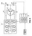
- Fig. 5 is a block diagram showing an outline of constitution of a power plant 20B according to an alternative example.
- Fig. 6 is a circuit diagram of the alternative example
power plant 20B and the diagram shows a u phase of the
three-phase coils of the
motor 22. - Fig. 7 is a flowchart exemplifying a circuit temperature
control processing routine to be executed by the
electronic control unit 40. - Fig. 8 shows a relationship between a reactor temperature Tl and a voltage ceiling value Vlmax and a relationship between a transistor temperature Tt and a voltage ceiling value Vtmax.
- Fig. 9 is a flowchart of an example circuit temperature
control processing routine to be executed by the
electronic control unit 40. - Fig. 10 shows a relationship between calorific values
of transistors T1 to T6 and coils of the
motor 22 and a switching frequency. - Fig. 11 is a block diagram showing an outline of the
constitution of a
power plant 120 according to the present invention. - Fig. 12 is a flowchart exemplifying a power temperature
rise processing routine to be executed by an
electronic control unit 140 of thepower plant 120 according to the present invention. - Fig. 13 is a flowchart exemplifying a DC-DC converter
temperature control processing routine to be executed by the
electronic control unit 140. - Fig. 14 shows a relationship between a reactor temperature T12 and a voltage ceiling value Vlmax2 and a relationship between a transistor temperature Tt2 and a voltage ceiling value Vtmax2.
- Fig. 15 is a flowchart exemplifying a DC-DC converter
temperature control processing routine to be executed by the
electronic control unit 140. - Fig. 16 shows a relationship between calorific values of transistors T7 and T8 and a reactor L and a switching frequency.
-
- The present invention will be described in more detail in the following with reference to the accompanying drawings.
- The invention is embodied in the example of figures 11 and following. The power plants of figures 1 to 10 are not according to the invention; however they are useful to the understanding of the invention.
- Fig. 1 is a block diagram showing an outline of outlining the constitution of a
power plant 20. Thepower plant 20 comprises amotor 22 which operates by a three-phase alternating current; aninverter circuit 24 capable of converting direct electric power into three-phase alternating current power and supplying the power converted to themotor 22; acapacitor 30 which is connected with apositive electrode bus 26 and anegative electrode bus 28 of theinverter circuit 24; a direct-current power source 32 which is connected with a neutral point of themotor 22 and thenegative electrode bus 28 of theinverter circuit 24; atemperature capacitor 50 for detecting a temperature of the direct-current power source 32; and anelectronic control unit 40 which controls the whole device. - The
motor 22 is, for example, a synchronous generator motor capable of generating electricity and comprising a rotor to the external surface of which is affixed a permanent magnet and a stator to which three-phase coils are wound. A rotation axis of themotor 22 is an output axis of the power plant according to the first embodiment and power is output from the output axis. Further, because theexample motor 22 according to the first embodiment is a generator motor, themotor 22 can generate electricity when power is input to its rotation axis. Additionally, when thepower plant 20 according to the first embodiment is installed in a vehicle, the rotation axis of themotor 22 is directly or indirectly connected with a wheel axle. - The
inverter circuit 24 comprises six transistors T1 to T6 and six diodes D1 to D6. The six transistors T1 to T6 are arranged in pairs so that these transistors will be a source side and a sink side toward thepositive electrode bus 26 and thenegative electrode bus 28, respectively, and each of the three-phase coils (u v w) of themotor 22 is connected with each node of the transistors. - The
capacitor 30 is constituted to function as a direct-current power source for driving themotor 22. The function of thecapacitor 30 will be described in detail below. Further, the direct-current power source 32 is, for example, a secondary battery of nickel metal hydride type or lithium ion type. The direct-current power source 32 has, for example, an accumulation capacity larger than the capacity of thecapacitor 30 at an identical voltage. - An
electronic control unit 40 is a microprocessor with aCPU 42 as the main component and comprises aROM 44 which stores a processing program, aRAM 46 which temporarily stores data, and input/output ports (not shown in the drawings). In theelectronic control unit 40, command values and the like concerning a power source temperature Tb from atemperature sensor 50 for detecting a temperature of the direct-current power source 32 and the operation of themotor 22 are input via the input port. From theelectronic control unit 40, a control signal or the like to be used for carrying out switching control of the transistors T1 to T6 of theinverter circuit 24 is output via the output port. - Operation of the
power plant 20 as described above will next be described. First, an example operation wherein thecapacitor 30 functions as a direct-current power source for supplying electricity to themotor 22 will be described. - Fig. 2 is a circuit diagram of the
power plant 20. The diagram shows the u phase of the three-phase coils of themotor 22. Considering a state that the transistor T2 of the u phase of theinverter circuit 24 is on, a short circuit as shown by the dotted arrow in the drawing is formed and the u phase of the three-phase coils of themotor 22 functions as a reactor. If the transistor T2 is turned off in this state, energy accumulated in the u phase of the three-phase coils which functions as a reactor will be accumulated in thecapacitor 30 via the circuit shown by the solid arrow in the drawing. A voltage at this time may be higher than a voltage of the direct-current power source 32. On the other hand, it is possible to charge the direct-current power source 32 via the circuit using an electric potential of thecapacitor 30. Therefore, this circuit can be considered to be a step-up and step-down chopper circuit which is capable of boosting energy of the direct-current power source 32 for accumulation of the energy in thecapacitor 30 and also charging the direct-current power source 32 using an electric potential of thecapacitor 30. The v and w phases of the three-phase coils of themotor 22 can also be considered to be a step-up and step-down chopper circuits similar to the u phase. Thus, it is possible to charge thecapacitor 30 by turning on or off the transistors T2, T4, and T6 or charge the direct-current power source 32 using electric potential storaged in thecapacitor 30. The potential difference resulting from charging thecapacitor 30 varies according to the quantity of electric charge to be storaged in thecapacitor 30, in other words, values of electric currents to be sent to the reactor. Thus, it is possible to control a voltage between terminals of thecapacitor 30 by switching control of the transistors T2, T4, and T6 of theinverter circuit 24 and controlling the currents to be sent to the reactor. In order to drive themotor 22 through such a circuit, it is only necessary to provide a pseudo three-phase alternating current to the three-phase coils of themotor 22 by controlling switching of the transistors T1 to T6 of theinverter circuit 24. If direct current components are added to the three-phase alternating current at this time, in other words, an electric potential of the three-phase alternating current is offset to the plus side or the minus side and the three-phase alternating current is supplied to themotor 22, it will be possible to drive themotor 22 using alternating current components while charging thecapacitor 30 using the direct current components. Therefore, by performing switching control of the transistors T1 to T6 of theinverter circuit 24, it is possible to drive themotor 22 while controlling a voltage between the terminals of thecapacitor 30. The voltage between the terminals of thecapacitor 30 is adjusted, for example, so as to be approximately twice as large as the voltage between terminals of the direct-current power source 32. - Next, operation of heating the direct-
current power source 32 when the direct-current power source 32 is in a low temperature state will be described. Fig. 3 is a flowchart exemplifying a power source temperature rise processing routine to be executed by theelectronic control unit 40 of thepower plant 20. This routine is executed at each prescribed time. - When the power source temperature rise processing routine is executed, the
CPU 42 of theelectronic control unit 40 first reads a power source temperature Tb of the direct-current power source 32 coming from the temperature sensor 50 (Step S100) and determines whether or not the power source temperature Tb read out exceeds a prescribed threshold Tblow (Step S102). Here, the threshold Tblow is a threshold to be used for determining whether or not the direct-current power source 32 can output a rated output or power which is required for driving themotor 22, and the threshold is determined based on specifications of a power source or the like. Whether or not necessary power or the like can be output based on the power source temperature Tb is first determined because internal resistance increases when the power source temperature Tb of the direct-current power source 32 becomes low, such that the power available for output to themotor 22 declines. When it is determined that the power source temperature Tb exceeds the threshold Tblow as a result, normal drive control (normal operation) of themotor 22 is carried out determining that necessary power can be supplied to the motor 22 (Step S104). More specifically, a torque command value is set based on a request received from themotor 22, and, based on the setting, switching control of the transistors T1 to T6 of theinverter circuit 24 is carried out so as to drive themotor 22. A switching frequency of the transistors T1 to T6 at this time, in other words, a frequency of a carrier wave is set so that the frequency is suitable for reducing the torque ripple of themotor 22 and decreasing a switching loss of the transistors T1 to T6 of theinverter circuit 24. - On the other hand, when it is determined that the power source temperature Tb is the threshold temperature Tblow or less, it is determined that the temperature is too low for the direct-
current power source 32 to provide adequate power, and processing of a heating operation for raising the internal temperature of the direct-current power source 32 is begun (Step S106). The processing for the heating operation is, as shown in Fig. 4, processing for making the ripple of a neutral point current flowing to a neutral point of themotor 22 larger than the ripple of a neutral point current generated during normal drive control of themotor 22. Because the direct-current power source 32 is more rapidly heated a larger neutral point current flows into it, its performance is enhanced. More precisely, a voltage between the terminals of thecapacitor 30 is set to a value larger than during normal drive control of themotor 22. For example, the voltage between the terminals of thecapacitor 30 may be set to a value twice the voltage between the terminals of the direct-current power source 32, and the frequency of the carrier wave is set to a low value. Switching control of the transistors T1 to T6 is then carried out based on this setting. Because the neutral point current which flows to the neutral point of themotor 22 vibrates at the same frequency as that of the carrier wave, when the frequency of the carrier wave is low and the switching frequency of the transistors T1 to T6 therefore becomes low, the neutral point current will generate great vibrations, or, in other words, the ripple of the current will become large. Because an electric potential at the neutral point of themotor 22 instantly changes within a range of the voltage between the terminals of thecapacitor 30, when the voltage between the terminals of thecapacitor 30 is set to be large, a ripple of the neutral point current will become large. Thus, it is possible to rapidly heat, while driving themotor 22, the direct-current power source 32 up to a temperature which enables the direct-current power source to provide adequate power. - In the
power plant 20 described above, when a temperature of the direct-current power source 32 is low, the frequency of the carrier wave is set to be low and the voltage between the terminals of thecapacitor 30 is set to be high, and switching control of the transistors T1 to T6 is carried out based on the set values. Thus, it is possible to send a current whose ripple is relatively large to the direct-current power source 32 and thereby rapidly heat up the direct-current power source 32 when its temperature is low. As a result, the direct-current power source 32 can perform to its full capacity. - In the
power plant 20, thecapacitor 30 is installed in such a manner that thepositive electrode bus 26 and thenegative electrode bus 28 of theinverter circuit 24 are connected. However, in a power plant 20B, an additional example shown in Fig. 5, it is also possible to install acapacitor 30B in such a manner that thepositive electrode bus 26 of theinverter circuit 24 is connected with the neutral point of themotor 22. In this example power plant 20B, the constitution can be considered to be the same in that a direct-current power source whose voltage is the sum of the voltage between the terminals of thecapacitor 30B and the voltage between the terminals of the direct-current power source 32 is installed so as to connect thepositive electrode bus 26 and thenegative electrode bus 28 of the inverter circuit. In other words, thecapacitor 30 of thepower plant 20 is installed so as to connect thepositive electrode bus 26 and thenegative electrode bus 28 of theinverter circuit 24. Hereinafter, operation concerning the setting of the voltage between the terminals of thecapacitor 30B will be described. - Fig. 6 is a circuit diagram of the power plant 20B which is a deformed example and at the diagram shows the u phase of the three-phase coils of the
motor 22. When the transistor T2 is turned on, the short circuit shown by a broken line arrow in the drawing is formed and the u phase of the three-phase coils of themotor 22 functions as a reactor. When the transistor T2 is turned off in this state, energy accumulated in the u phase of the three-phase coils which functions as a reactor is accumulated in thecapacitor 30B via the circuit shown by a continuous line arrow in the drawing. On the other hand, by turning off the transistor T1, the direct-current power source 32 can be charged using electric charge from thecapacitor 30B. Therefore, this circuit can be considered to be a chopper circuit which is capable of accumulating energy of the direct-current power source 32 in thecapacitor 30B and also of charging the direct-current power source 32 using the electric potential of thecapacitor 30B. Because the v and w phases of themotor 22 can similarly be considered a chopper circuits similar to the u phase, it is possible to charge thecapacitor 30B by turning on or off the transistors T1 to T6 and charge the direct-current power source 32 using electric charges which are accumulated in thecapacitor 30B. A potential difference which arises resulting from charging of thecapacitor 30B varies according to the quantity of electric charges accumulated in thecapacitor 30B, namely, values of currents to be sent to the reactor. Thus, it is possible to control the voltage between the terminals of thecapacitor 30B by performing switching control of the transistors T1 to T6 of theinverter circuit 24 and controlling the values of currents to be sent to the reactor. To drive themotor 22 using circuits as described, it is merely necessary to supply a pseudo three-phase alternating current to the three-phase coils of themotor 22 by performing switching control of the transistors T1 to T6 of theinverter circuit 24. If direct current components are added to the three-phase alternating current at this time, in other words, if an electric potential of the three-phase alternating current is offset to the plus side or the minus side and the three-phase alternating current is supplied to themotor 22, themotor 22 can be driven using alternating current components while thecapacitor 30B is charged using direct current components. Therefore, it is possible to drive themotor 22 while the voltage between the terminals of thecapacitor 30 is adjusted by switching control of the transistors T1 to T6 of theinverter circuit 24. Thus, even in the alternate example power plant 20B, it is possible to set the voltage between the terminals of thecapacitor 30B similarly to thepower plant 20 and execute a temperature rise control processing routine shown in Fig. 3. Here it should be noted that in normal driving of themotor 22, the voltage between the terminals of thecapacitor 30B is adjusted to be, for example, almost the same as the voltage between the terminals of the direct-current power source 32, and when the direct-current power source 32 has a low temperature, the voltage between the terminals of thecapacitor 30B is set to be higher than the voltage between the terminals of the direct-current power source 32. - In the
power plant 20, the direct-current power source 32 is installed in such a manner that thenegative electrode bus 28 of theinverter circuit 24 is connected with the neutral point of themotor 22. However, it is also possible to install the direct-current power source 32 in such a manner that thepositive electrode bus 26 of theinverter circuit 24 is connected with the neutral point of themotor 22. Further, in the power plant 20B which is an alternate example, the direct-current power source 32 is installed in such a manner that thenegative electrode bus 28 of theinverter circuit 24 is connected with the neutral point of themotor 22 and thecapacitor 30B is installed in such a manner that thepositive electrode bus 26 of theinverter circuit 24 is connected with the neutral point of themotor 22. However, it is also possible to install thecapacitor 30B in such a manner that thenegative electrode bus 28 of theinverter circuit 24 is connected with the neutral point of themotor 22 and also to install the direct-current power source 32 in such a manner that thepositive electrode bus 26 of theinverter circuit 24 is connected with the neutral point of themotor 22. - In the
power plant 20 and the power plant 20B which is the deformed example, a frequency of a carrier wave is set to be low so as to heat the direct-current power source 32 while the voltage between the terminals of thecapacitor 30 is set to be high so as to carry out switching control of the transistors T1 to T6, but it is also possible to employ either one of the above. It should also be noted that if the voltages between the terminals of thecapacitors capacitors - In the
power plant 20 and the power plant 20B according to the alternate example, it is arranged such that the direct-current power source 32 is heated by switching control of the transistors T1 to T6. However, it is also possible to adopt other methods such as, for example, direct heating of a direct-current power source using a heater or the like. - The
power plant 20 and the power plant 20B of the alternate example is configured such that when the power source temperature Tb of the direct-current power source 32 is the threshold Tblow or below, heating operation for heating the direct-current power source 32 is carried out. However, it is possible to configure the invention such that when the power source temperature Tb of the direct-current power source 32 is a threshold Tbhi or above, temperature rise restraint operation to restrain a temperature rise of the direct-current power source 32 is carried out. Processing of the temperature rise restraint operation is a reverse processing of the heating operation processing at Step S106 of a routine shown in Fig. 3, in other words, a process of making the ripple of the neutral point current smaller than a ripple of the neutral point current which arises resulting from a normal operation processing at Step S104 of the routine shown in Fig. 3. When the neutral point current whose ripple becomes small flows into the direct-current power source 32, it is possible to control a calorific value which arises due to internal resistance of the direct-current power source 32. Also, the direct-current power source 32 can fully demonstrate the performance because the temperature rise is restrained. More specifically, the voltage between the terminals of thecapacitor 30 is set to be lower than a voltage between the terminals to be required at the time of normal operation (for example, lower than a voltage which is twice as high as the voltage between the terminals of the direct-current power source 32), while the frequency of the carrier wave is set to be higher than the frequency at the time of normal operation. Based on the setting, switching control of the transistors T1 to T6 is carried out. Here, it is obvious that with regard to the processing of temperature rise restraint operation, either of the setting of the voltage between the terminals of thecapacitor 30 and the setting of the frequency of the carrier wave may be put into practice. - In the
power plant 20, the power plant 20B, and the various example of these devices, it is arranged such that, according to the power source temperature Tb of the direct-current power source 32, a process of heating the direct-current power source 32 and a process of restraining the temperature rise are carried out. However, switching control of the transistors T1 to T6 of theinverter circuit 24 may also be based on a temperature of the step-up and step-down chopper circuit which is composed of a coil of each phase of themotor 22 functioning as a step-up and step-down reactor and the transistors T1 to T6 of theinverter circuit 24 functioning as a switch for set-up and set-down chopping, for example according to the temperature of the coil of each phase of themotor 22 and the temperatures of the transistors T1 to T6. Fig. 7 is a flowchart exemplifying a circuit temperature control processing routine to be executed by theelectronic control unit 40. The routine is repeatedly executed at a prescribed interval. - When the circuit temperature control processing routine is executed, the
CPU 42 of theelectronic control unit 40 first reads a temperature (reactor temperature Tl) of the coil of each phase of themotor 22 detected by atemperature sensor 52 and temperatures (transistor temperature Tt) of the transistors T1 to T6 of theinverter circuit 24 detected by a temperature sensor 54 (Step S110). Based on the reactor temperature Tl and the read out transistor temperature Tt, a ceiling value Vmax of the voltage between the terminals of thecapacitor 30 is set (Step S112) and switching control of the transistors T1 to T6 of theinverter circuit 24 is performed within a range in which the voltage between the terminals of thecapacitor 30 does not exceed the ceiling value Vmax set (Step S114), which ends the routine. For setting of the ceiling value Vmax of the voltage between the terminals of thecapacitor 30 in the embodiment, a relationship between the reactor temperature Tl and a ceiling value Vlmax of the voltage between the terminals of thecapacitor 30 and a relationship between the transistor temperature Tt and the ceiling value Vlmax of the voltage between the terminals of thecapacitor 30 are found through experiment or the like, and stored in thePOM 44 as maps. When the reactor temperature Tl and the transistor temperature Tt are given, the ceiling value Vlmax and the Vtmax corresponding to the maps are obtained, and a smaller value among these values is obtained as the ceiling value Vmax of the voltage between the terminals of thecapacitor 30. The voltage between the terminals of thecapacitor 30 is set to be lower than normal for the purposes of restraining a ripple of a current to be applied to the coil of each phase of themotor 22 and also restraining calorific values which arise due to switching of the transistors T1 to T6 of theinverter circuit 24. Fig. 8 shows maps of the relationship between the reactor temperature Tl and the ceiling value Vlmax of the voltage between the terminals of thecapacitor 30 and the relationship between the transistor temperature Tt and the ceiling value Vtmax of the voltage between the terminals of thecapacitor 30. By thus imposing restrictions on the voltage between the terminals of thecapacitor 30 according to the temperature of the coil of each phase of themotor 22 and the temperatures of the transistors T1 to T6 of theinverter circuit 24, it is possible to protect the coil of each phase of themotor 22 and the transistors T1 to T6 from overheating, and thereby secure stable operation. Although the alternate example is configured such that the ceiling value Vmax of the voltage between the terminals of thecapacitor 30 is set based on the reactor temperature Tl of the coil of each phase of themotor 22 and the transistor temperature Tt of the transistors T1 to T6, it is also possible to employ an arrangement wherein the ceiling value Vmax of the voltage between the terminals of thecapacitor 30 is set based on either the reactor temperature Tl or the transistor temperature Tt. - In the alternate example described above, the coil of each phase of the
motor 22 and the transistors T1 to T6 are protected from overheating by restricting the voltage between the terminals of thecapacitor 30. However, the coil of each phase of themotor 22 and the transistors T1 to T6 can also be protected from overheating by controlling a switching frequency of the transistors T1 to T6. Fig. 9 is a flowchart exemplifying a circuit temperature control processing routine to be executed by theelectronic control unit 40. When the circuit temperature control processing routine is executed, theCPU 42 of theelectronic control unit 40 first reads the reactor temperature Tl and the transistor temperature Tt detected by thetemperature sensor 52 and a temperature sensor 54 (Step S120), and the switching frequency (frequency of a carrier wave) of the transistors T1 to T6 are set based on the reactor temperature Tl and the read out transistor temperature Tt (Step S122). Switching control of the transistors T1 to T6 is then carried out at the set switching frequency (Step S124). Here, with regard to the processing of setting the switching frequency of the transistors T1 to T6 in this example, when the reactor temperature Tl meets or exceeds a threshold temperature Tlhi, the switching frequency is set to be, for example, higher than the switching frequency which is set at the time of normal operation at Step S104 of the routine of Fig. 3. Similarly, when the transistor temperature Tt exceeds a threshold temperature Tthi, the switching frequency is set to be lower than the switching frequency which is set at the time of normal operation. Fig. 10 shows a relationship between the switching frequency and a calorific value of the coil of each phase of themotor 22 and calorific values of the transistors T1 to T6. As shown in Fig. 10, the as the switching frequency increases, the calorific value of the coil of each phase decreases. Meanwhile, as the switching frequency decreases, the calorific values of the transistors T1 to T6 decrease. Therefore, when the coil of each phase of themotor 22 which functions as a reactor is overheated due to, for example, a breakdown of a cooling system, the switching frequency is heightened, and when the transistors T1 to T6 are overheated, the switching frequency is lowered, whereby it is possible to protect a part which functions as a step-up and step-down chopper circuit from overheating and secure the stable operation. - In such a
power plant 20 and the alternate example, it is also possible for a storage such as a CD-ROM, a DVD-ROM, a floppy disc, or the like to be used as a storage medium which stores a computer readable program for causing a computer to function as a control system for performing temperature control processing of the direct-current power source 32 and temperature control processing of the coil of each phase of themotor 22 and the transistors T1 to T6. Effects of the present invention can be achieved by installing the program according to the embodiment of the present invention into an electronic control system and executing the program using such a storage medium. - Next, a
power plant 120 according to the present invention will be described. Fig. 11 is a block diagram showing an outline of the constitution of thepower plant 120 according to the invention. As shown in Fig. 11, thepower plant 120 according to the invention has the same constitution as that of thepower plant 20 previously described except that a DC-DC converter 148 which carries out step-up and step-down operation is provided instead of causing the coil of each phase of themotor 22 and the transistors T1 to T6 and the diodes D1 to D6 of theinverter circuit 24 in thepower plant 20 previously described to function as the step-up and step-down chopper circuit. More specifically, thepower plant 120 according to the invention comprises amotor 122 which drives by a three-phase alternating current; aninverter circuit 124 which is capable of converting a electric current power into three-phase alternating current power and supplying the power to themotor 122; acapacitor 130 which is connected with apositive electrode bus 126 and anegative electrode bus 128 of theinverter circuit 124; a direct-current power source 132 which can charge and discharge; a DC-DC converter 148 which is capable of boosting a direct-current voltage from the direct-current power source 132 and supplying the direct-current voltage to thecapacitor 130; atemperature sensor 150 which detects a temperature of the direct-current power source 132; and anelectronic control unit 140 which controls the entire device. Among the components of thepower plant 120 according to the invention, the components corresponding to those of thepower plant 20 previously described are designated by reference numerals increased by 100 over the reference numerals used before, and the detailed description will not be repeated. - The DC-
DC converter 148 comprises two transistors T7 and T8 configured in such a manner that these transistors become a source side and a sink side toward thepositive electrode bus 126 and thenegative electrode bus 128 of theinverter circuit 124; two diodes D7 and D8 which are connected with the transistors T7 and T8,respectively, in such a manner that the diodes and the transistors are parallel to each other and the direction of current flow of the former is opposite to that of the latter; and a reactor L which is connected with a node M of the transistors T7 and T8. Further, theelectronic control unit 140 outputs a control signal to be used for performing switching control of the transistors T7 and T8 of the DC-DC converter 148. - Operation of the
power plant 120 according to the invention constituted in such a manner, particularly operation of heating the direct-current power source 132 when the direct-current power source 132 has a low temperature will be described. Fig. 12 is a flowchart exemplifying a power source temperature rise processing routine to be executed by theelectronic control unit 140 of thepower plant 120 according to the invention. This routine is repeatedly executed at each prescribed interval. - When the power source temperature rise processing routine is executed, a
CPU 142 of theelectronic control unit 140 first reads a battery temperature Tb2 of the direct-current power source 132 (Step S200) and determines whether or not the detected power source temperature Tb2 exceeds a threshold temperature Tblow2 (Step S202). As a result of the determination, when the power source temperature Tb exceeds the threshold Tblow2, it is determined that the direct-current power source 132 can supply adequate power to themotor 122, and drive control (processing of normal operation) of the DC-DC converter 148 is carried out using the voltage between the terminals of thecapacitor 130 and the switching frequency of the transistors T7 and T8 which are set at the time of normal driving of the motor 122 (Step S204). When the power source temperature Tb is at or below the threshold temperature Tblow2, it is determined that the direct-current power source 132 cannot supply adequate power to themotor 122 because the temperature of the direct-current power source is too low, and a processing of heating operation to heat the direct-current power source 132 is carried out (Step S206), which completes this routine. The processing of heating operation is a process of making a ripple of the current which flows the reactor L larger than a ripple which arises resulting during normal operation at Step S204. When the enlarged ripple of the current flows into the direct-current power source 132, calorification due to the internal resistance of the direct-current power source 132 is promoted and the direct-current power source 132 can rapidly be heated, whereby the performance can fully be demonstrated. To be concrete, the voltage between the terminals of thecapacitor 130 is set to be higher than the voltage between the terminals of thecapacitor 130 required at the time of normal driving of themotor 122 and also a switching frequency (frequency of a carrier wave) of the transistors T7 and T8 of the DC-DC converter 148 is set to be lower than normal. The processing is carried out by drive control of the DC-DC converter 148 based on this setting, based on the property that, when the electric potential of the node M of the transistors T7 and T8 changes within a range of the voltage between the terminals of thecapacitor 130 and at the same frequency as the switching frequency of the transistors T7 and T8, the voltage between the terminals of thecapacitor 130 increases, and the switching frequency of the transistors T7 and T8 is lowered, the ripple of the current flowing through the direct-current power source 132 increases. - In the
power plant 120 according to the invention described above, when the direct-current power source 132 has a low temperature, the voltage between the terminals of thecapacitor 130 is set to be higher than the voltage during normal operation and also the switching frequency (frequency of a carrier wave) of the transistors T7 and T8 is set to a lowered value. Drive control of the DC-DC converter 148 is performed using this setting such that it becomes possible to provide the direct-current power source 132 with a current whose ripple is relatively large and to rapidly heat the direct-current power source 132. Therefore, it is possible to achieve effects similar to those of the power plant previously described. - The
power plant 120 according to the invention is configured such that the power source temperature Tb2 of the direct-current power source 132 is the threshold Tblow2 or below, heating operation for heating the direct-current power source 132 is carried out. However, it is also possible to employ an arrangement such that when the power source temperature Tb of the direct-current power source 132 is at or above the threshold temperature Tbhi2, a temperature rise restraint operation for restraining a temperature rise of the direct-current power source 132 is employed so as to prevent degradation of the performance of the direct-current power source 132 by excessively high temperatures. The processing of the temperature rise restraint operation is the reverse of the processing of heating operation at Step S206 of the routine shown in Fig. 12, namely, a process of making a ripple of a current which flows the direct-current power source 132 smaller than a ripple of current which arises due to a processing of normal operation at Step 204 of the routine shown in Fig. 12. If the current whose ripple has become small flows into the direct-current power source 132, it will be possible to restrain the calorific value which arises due to internal resistance of the direct-current power source 132, whereby the temperature rise can be restrained. More specifically, the voltage is set to be lower than the voltage between the terminals of thecapacitor 130 during normal drive control (during normal operation) of themotor 122 and the switching frequency (frequency of a carrier wave) of the transistors T7 and T8 is set to a higher frequency, and switching control of the transistors T7 and T8 of the DC-DC converter 148 is based on this setting. Here, it is obvious that in a processing of the temperature rise restraint operation, either of the setting of the voltage between the terminals of thecapacitor 130 and the setting of the frequency of the carrier wave may be executed. - In the
power plant 120 according to the invention and the alternate example, a process of heating the direct-current power source 132 and a process of restraining the temperature rise are carried out according to the power source temperature Tb2 of the direct-current power source 132. However, it is also possible to employ an arrangement such that temperature control of the DC-DC converter 148 is performed through switching control of the transistors T7 and T8 according to the temperature of the DC-DC converter 148, for example the temperatures of the reactor L and the transistors T7 and T8. Fig. 13 is a flowchart exemplifying a DC-DC converter temperature control processing routine to be executed by theelectronic control unit 140. This routine is repeatedly executed at prescribed intervals. - When the DC-DC converter temperature control processing routine is executed, the
CPU 142 of theelectronic control unit 140 first reads the temperature of the reactor L (reactor temperature Tl2) detected by a temperature sensor 152 and the temperatures of the transistors T7 and T8 (transistor temperature Tt2) detected by a temperature sensor 154 (Step S210). Based on the detected reactor temperature Tl2 and transistor temperature Tt2, the ceiling value Vmax2 of the voltage between the terminals of thecapacitor 130 is then set (Step S212) and switching control of the transistors T7 and T8 of the DC-DC converter 148 is performed within a range which the voltage between the terminals of thecapacitor 130 does not exceed the ceiling value Vmax2 set (Step S214), which completes this routine. With regard to setting of the ceiling value Vmax2 of the voltage between the terminals of thecapacitor 130 in this embodiment, a relationship between the reactor temperature T12 and the ceiling value Vlmax2 of the voltage between the terminals of thecapacitor 130 and a relationship between the transistor temperature Tt2 and the ceiling value Vtmax of the voltage between the terminals of thecapacitor 130 are previously found by experiment or the like, and are stored as maps in theROM 144. When the reactor temperature Tl2 and the transistor temperature Tt2 are given, the ceiling values Vlmax2 and Vtmax2 corresponding to the maps are obtained, and the smaller value among these values is obtained as the ceiling value Vmax2 of the voltage between the terminals of thecapacitor 130. Restrictions are imposed on the voltage between the terminals of thecapacitor 130 so as to hold down the ripple of the current which flows into the reactor L to a low level and also restrain calorification which may arise due to switching of the transistors T7 and T8 of the DC-DC converter 148. Fig. 14 shows maps which indicate a relationship between the reactor temperature Tl2 and the ceiling value Vlmax2 of the voltage between the terminals of thecapacitor 130 and a relation between the transistor temperature Tt2 and the ceiling value Vtmax2 of the voltage between the terminals of thecapacitor 130. Thus, by imposing restrictions on the voltage between the terminals of thecapacitor 130 according to the temperature of the reactor L and the temperatures of the transistors T7 and T8 of the DC-DC converter 148, the DC-DC converter 148 can be protected from overheating and stable operation can be secured. Incidentally, in this alternate example, the invention is configured such that based on the reactor temperature Tl2 and the transistor temperature Tt2, the ceiling value Vmax2 of the voltage between the terminals of thecapacitor 130 is set. However, it is also possible to employ a configuration such that based on either of the reactor temperature Tl2 and the transistor temperature Tt2, the ceiling value Vmax2 of the voltage between the terminals of thecapacitor 130 is set. Further, it is also possible to set the ceiling value Vmax2 of the voltage between the terminals of thecapacitor 130 based on the internal temperature of the DC-DC converter 148 excluding the reactor L and the transistors T7 and T8. - In the alternate example described above, is the invention is configured such that the DC-
DC converter 148 is protected from overheating by imposing restrictions on the voltage between the terminals of thecapacitor 130. However, it is also possible to protect the DC-DC converter 148 from overheating by controlling a switching frequency of the transistors T7 and T8. Fig. 15 is a flowchart exemplifying a DC-DC converter temperature control processing routine to be executed by theelectronic control unit 140 in such a case. When the DC-DC converter temperature control processing routine is executed, theCPU 142 of theelectronic control unit 140 first reads the reactor temperature Tl2 and the transistor temperature Tt2 detected by the temperature sensors 152 and 154 (Step S220) and based on the detected reactor temperature Tl2 and transistor temperature Tt2, a switching frequency (frequency of a carrier wave) of the transistors T7 and T8 is set (Step S222). Switching control of the transistors T7 and T8 of the DC-DC converter 148 is carried out (Step S224) at the set frequency, thereby completing this routine. Here, with regard to setting of the switching frequency in this deformed example, when the reactor temperature Tl2 becomes the threshold Tlhi2 or above, the switching frequency is set to be higher than, for example, the switching frequency to be set at the time of normal operation at Step S204 of the routine shown in Fig. 12, and when the transistor temperature Tt2 becomes the threshold Tthi2 or above, the switching frequency is set to be lower than the switching frequency to be set at the time of normal operation. Fig. 16 shows a relationship between a switching frequency and a calorific value of the reactor L and calorific values of the transistors T7 and T8. As shown in Fig. 16, the greater the switching frequency, the greater the decrease in the calorific value of the reactor L, while as the switching frequency becomes low, the calorific values of the transistors T7 and T8 decrease. Therefore, when the reactor L is overheated, for example, due to a breakdown of a cooling system of the DC-DC converter 148, the switching frequency is increased, and when the transistors T7 and T8 are overheated, the switching frequency is lowered, whereby the DC-DC converter 148 can be protected from overheating and the stable operation can be secured. - The
power plant 120 according to the invention and the alternate example is configured such that a temperature of the direct-current power source 132 which serves as a power source for driving themotor 122 is controlled. However, it is also possible to configure the power plant such that it will be applicable to a device which controls a temperature of a direct-current power source serving as a power source for driving an ordinary power consuming load. Further, it is also possible to have an aspect such that a storage media such as, for example, a CD-ROM, a DVD-ROM, a floppy disc, or the like, can be used as a storage medium which stores a computer readable program for causing a computer to function as a control system to carry out a processing of temperature control of the direct-current power source 132 and a processing of temperature control of the DC-DC converter 148 (the reactor L and the transistors T7 and T8). Effects of the present invention can be achieved by installing the program according to the embodiment of the present invention into a control system and executing the program by utilizing such a storage medium. - In the
power plants motors - The embodiments of the present invention are described using the aspects hereinbefore, but the present invention is not restricted to such aspects. The present invention can be reduced to practice in various embodiments which will not deviate from the subject matter of the present claims.
- As described above, the drive unit according to the present invention, a vehicle which carries the drive unit, a control method, a storage medium, and a program of the drive unit are suitable for controlling a temperature of the power source which serves as a power source of a motor or other electrical appliances to be loaded as a drive source of a vehicle, such as a car, or controlling a temperature of a power converter which intervenes between the power source and the electrical appliance.
Claims (17)
- A drive unit comprising:characterized in that the drive unit further comprisesa DC-DC converter (148) which has energy accumulating means capable of temporarily accumulating a DC current as energy and which is capable of performing, by switching switching elements (T7, T8), DC-DC conversion of an input direct current utilizing the energy accumulated in said energy accumulating means and providing a load with the DC-DC converted voltage;a power source (132) capable of supplying DC power to said DC-DC converter;
temperature control means (140, 150, 152, 154) for performing, based on a temperature of said power source or a temperature of said DC-DC converter, switching control of said switching elements so as to control said temperature. - The drive unit according to claim 1, additionally comprising a electric storage device (130) capable of storing power output from said DC-DC converter, wherein said temperature control means are means for controlling a charged voltage of said electric storage device by switching control based on a temperature of said power source or a temperature of said DC-DC converter.
- The drive unit according to claim 2, wherein said temperature control means are means for performing switching control such that a charged voltage of said electric storage device is higher than normal when a temperature of said power source is at or below a first threshold temperature.
- The drive unit according to claim 2 or claim 3, wherein said temperature control means are means for performing switching control such that a charged voltage of said electric storage device is lower than normal when a temperature of said power source is at or above a second threshold temperature.
- The drive unit according to any one of claims 2 through 4, wherein said temperature control means are means for imposing restrictions on a charged voltage of said electric storage device and performing switching control when a temperature of said DC-DC converter is at or above a third threshold temperature.
- The drive unit according to any one of claims 1 through 5, wherein said temperature control means are means for setting a switching frequency of said switching elements based on a temperature of said power source or a temperature of said DC-DC converter and performing switching control at the set switching frequency.
- The drive unit according to claim 6, wherein said temperature control means are means for setting said switching frequency lower than normal and performing switching control when a temperature of said power source is at or below a fourth threshold temperature.
- The drive unit according to claim 6 or claim 7, wherein said temperature control means are means for setting said switching frequency higher than normal and performing switching control when a temperature of said power source is at or above a fifth threshold temperature.
- The drive unit according to any one of claims 6 through 8, said temperature control means are means for setting said switching frequency lower than normal and performing switching control when at least a temperature of said switching elements is at or above a sixth threshold temperature.
- The drive unit according to claim 9, wherein said temperature control means are means for setting a switching frequency of said switching elements higher than normal and performing switching control when a temperature of said energy accumulating means is at or above a seventh threshold temperature.
- The drive unit according to any one of claims I through 10, wherein said load is an electric motor (122) which operates by a polyphase current and there is provided an inverter circuit (124) capable of converting into a polyphase electric power direct current power converted by said DC-DC converter and supplying the polyphase electric power to said electric motor.
- A vehicle on which is installed the drive unit and the electric motor according to claim 11.
- A control method of a drive unit, wherein said drive unit comprises:and wherein, based on a temperature of said power source or a temperature of said DC-DC converter, switching control of said switching elements is performed so as to control said temperature.a DC-DC converter which has energy accumulating means capable of temporarily accumulating a DC current as energy and which is capable of performing, by switching switching elements, DC-DC conversion of an input direct-current voltage input utilizing said energy accumulating means and providing a load with the DC-DC converted voltage; anda power source capable of supplying a direct current to said DC-DC converter,
- The control method of a drive unit according to claim 13, wherein, based on a temperature of said power source or temperatures of said switching elements, a charged voltage of an electric storage device included in the drive unit and capable of storing power output from said DC-DC converter is controlled by switching control.
- The control method of a drive unit according to claim 13 or claim 14, wherein, based on a temperature of said power source or a temperature of said DC-DC converter, a switching frequency of said switching elements is set and switching control is carried out at said set switching frequency.
- A computer program, causing a computer to perform the switching control of claim 13 when said computer programm is run on a computer.
- A computer readable storage medium on which a computer programm according to claim 16 is stored.
Applications Claiming Priority (3)
| Application Number | Priority Date | Filing Date | Title |
|---|---|---|---|
| JP2001037007 | 2001-02-14 | ||
| JP2001037007 | 2001-02-14 | ||
| PCT/JP2001/008751 WO2002065628A1 (en) | 2001-02-14 | 2001-10-04 | Power outputting device and vehicle mounting it, control method, storing medium and program for the power outputting device, drive device and vehicle mounting it, and, control method, storing medium and program for the drive device |
Publications (3)
| Publication Number | Publication Date |
|---|---|
| EP1286459A1 EP1286459A1 (en) | 2003-02-26 |
| EP1286459A4 EP1286459A4 (en) | 2003-05-14 |
| EP1286459B1 true EP1286459B1 (en) | 2005-10-05 |
Family
ID=18900195
Family Applications (1)
| Application Number | Title | Priority Date | Filing Date |
|---|---|---|---|
| EP01974686A Expired - Lifetime EP1286459B1 (en) | 2001-02-14 | 2001-10-04 | Drive device and control method, storing medium and program for the drive device |
Country Status (7)
| Country | Link |
|---|---|
| US (1) | US7120037B2 (en) |
| EP (1) | EP1286459B1 (en) |
| JP (1) | JP3732828B2 (en) |
| KR (1) | KR100486321B1 (en) |
| CN (1) | CN1211908C (en) |
| DE (1) | DE60113832T2 (en) |
| WO (1) | WO2002065628A1 (en) |
Families Citing this family (70)
| Publication number | Priority date | Publication date | Assignee | Title |
|---|---|---|---|---|
| JP3692993B2 (en) * | 2001-10-04 | 2005-09-07 | トヨタ自動車株式会社 | DRIVE DEVICE AND POWER OUTPUT DEVICE |
| US6917179B2 (en) * | 2001-10-25 | 2005-07-12 | Toyota Jidosha Kabushiki Kaisha | Load driver and control method for safely driving DC load and computer-readable recording medium with program recorded thereon for allowing computer to execute the control |
| JP3661689B2 (en) * | 2003-03-11 | 2005-06-15 | トヨタ自動車株式会社 | Motor drive device, hybrid vehicle drive device including the same, and computer-readable recording medium storing a program for causing a computer to control the motor drive device |
| US7737658B2 (en) * | 2003-10-27 | 2010-06-15 | Sony Corporation | Battery packs having a charging mode and a discharging mode |
| JP4461824B2 (en) * | 2004-02-13 | 2010-05-12 | トヨタ自動車株式会社 | Vehicle, vehicle control method, and computer-readable recording medium recording a program for causing a computer to execute the control method |
| FI119579B (en) * | 2004-08-13 | 2008-12-31 | Abb Oy | Method in Voltage Intermediate Drive and Frequency Converter |
| JP4113527B2 (en) * | 2004-11-25 | 2008-07-09 | トヨタ自動車株式会社 | Power output apparatus and vehicle equipped with the same |
| JP4839780B2 (en) * | 2004-12-28 | 2011-12-21 | トヨタ自動車株式会社 | Motor control device and vehicle |
| US7792860B2 (en) * | 2005-03-25 | 2010-09-07 | Oracle International Corporation | System for change notification and persistent caching of dynamically computed membership of rules-based lists in LDAP |
| JP4797476B2 (en) * | 2005-07-12 | 2011-10-19 | トヨタ自動車株式会社 | Secondary battery control device |
| DE102005042324A1 (en) * | 2005-09-06 | 2007-03-15 | Siemens Ag | Wide-voltage-converter |
| KR100659313B1 (en) * | 2005-12-06 | 2006-12-19 | 삼성전자주식회사 | Driving apparatus of bldc motor |
| EP1796262B1 (en) * | 2005-12-07 | 2009-11-04 | Denso Corporation | Control apparatus for electric vehicles |
| JP2007166874A (en) * | 2005-12-16 | 2007-06-28 | Toyota Motor Corp | Voltage converter |
| JP4640200B2 (en) * | 2006-02-10 | 2011-03-02 | トヨタ自動車株式会社 | Voltage conversion device and voltage converter control method |
| JP4479919B2 (en) * | 2006-03-29 | 2010-06-09 | 株式会社デンソー | Electric vehicle control device |
| JP4544273B2 (en) * | 2007-06-20 | 2010-09-15 | トヨタ自動車株式会社 | VEHICLE POWER SUPPLY DEVICE AND CHARGING STATE ESTIMATION METHOD FOR POWER STORAGE DEVICE IN VEHICLE POWER SUPPLY DEVICE |
| JP4274271B2 (en) | 2007-07-26 | 2009-06-03 | トヨタ自動車株式会社 | Voltage converter |
| WO2009040280A1 (en) * | 2007-09-24 | 2009-04-02 | Robert Bosch Gmbh | Method and device for controlling an electric motor |
| JP4380755B2 (en) * | 2007-10-10 | 2009-12-09 | 株式会社デンソー | Rotating electrical machine equipment |
| US8556011B2 (en) * | 2007-11-01 | 2013-10-15 | GM Global Technology Operations LLC | Prediction strategy for thermal management and protection of power electronic hardware |
| JP5221119B2 (en) * | 2007-12-14 | 2013-06-26 | 株式会社東芝 | Inverter device |
| JP4957538B2 (en) * | 2007-12-27 | 2012-06-20 | アイシン・エィ・ダブリュ株式会社 | Converter device, rotating electrical machine control device, and drive device |
| JP4708483B2 (en) * | 2008-03-18 | 2011-06-22 | 株式会社デンソー | Synchronous motor drive device |
| US8625315B2 (en) * | 2008-05-09 | 2014-01-07 | Etm Electromatic Inc | Inverter modulator with variable switching frequency |
| JP5412974B2 (en) * | 2009-03-13 | 2014-02-12 | 株式会社デンソー | Driving device for three-phase AC synchronous motor |
| JP5304423B2 (en) * | 2009-05-08 | 2013-10-02 | トヨタ自動車株式会社 | Power output system, control method therefor, and vehicle equipped with power output system |
| JP4811503B2 (en) | 2009-07-08 | 2011-11-09 | トヨタ自動車株式会社 | Secondary battery temperature increase control device, vehicle equipped with the same, and secondary battery temperature increase control method |
| EP2453514B1 (en) * | 2009-07-08 | 2017-11-22 | Toyota Jidosha Kabushiki Kaisha | Secondary-battery temperature-raising apparatus and vehicle having same |
| JP4840481B2 (en) * | 2009-07-08 | 2011-12-21 | トヨタ自動車株式会社 | Secondary battery temperature increase control device, vehicle equipped with the same, and secondary battery temperature increase control method |
| DE102009045147A1 (en) * | 2009-09-30 | 2011-04-07 | Robert Bosch Gmbh | Method for protecting a motor vehicle generator against overheating |
| US8749090B2 (en) * | 2010-02-03 | 2014-06-10 | GM Global Technology Operations LLC | Dual source automotive propulsion system and method of operation |
| US8750008B2 (en) | 2010-02-17 | 2014-06-10 | Toyota Jidoha Kabushiki | Multi-phase converter for DC power supply with two choppers having magnetically coupled reactors |
| JP5375715B2 (en) * | 2010-03-31 | 2013-12-25 | 株式会社豊田自動織機 | Neutral point boost DC-three-phase converter |
| JP5059160B2 (en) * | 2010-04-19 | 2012-10-24 | 三菱電機株式会社 | DC / DC voltage converter |
| JP5502603B2 (en) * | 2010-06-04 | 2014-05-28 | 本田技研工業株式会社 | Vehicle battery heating device |
| JP5294335B2 (en) * | 2010-06-18 | 2013-09-18 | 三菱電機株式会社 | Semiconductor device |
| DE102010042328A1 (en) * | 2010-10-12 | 2012-04-12 | Robert Bosch Gmbh | Method for monitoring the charging operation of an energy storage device in a vehicle and charging system for charging an energy storage device in a vehicle |
| CN102479983B (en) * | 2010-11-30 | 2016-03-02 | 比亚迪股份有限公司 | For charge control method and the device of electric automobile power battery |
| EP2662921B1 (en) * | 2011-01-07 | 2018-10-10 | Mitsubishi Electric Corporation | Charging and discharging apparatus |
| WO2012114902A1 (en) * | 2011-02-25 | 2012-08-30 | Ntn株式会社 | Electric automobile |
| JP5925425B2 (en) * | 2011-04-07 | 2016-05-25 | サンデンホールディングス株式会社 | Inverter device |
| JP5834768B2 (en) * | 2011-10-25 | 2015-12-24 | 株式会社デンソー | Generator motor control device |
| DE102011088974A1 (en) * | 2011-12-19 | 2013-06-20 | Continental Automotive Gmbh | Method for start-up control of an electric vacuum pump |
| JP5973173B2 (en) * | 2012-01-23 | 2016-08-23 | 東京エレクトロン株式会社 | Heat treatment apparatus and control method for heat treatment apparatus |
| KR101323921B1 (en) * | 2012-04-24 | 2013-10-31 | 엘에스산전 주식회사 | Power conversion device and operating method thereof |
| US9352656B2 (en) * | 2012-08-31 | 2016-05-31 | Ford Global Technologies, Llc | Temperature based electric machine control |
| CA2884597C (en) * | 2012-09-13 | 2022-04-05 | Moog Inc. | Methods and apparatae for controlling and providing a voltage converter with a pulse-width-modulated switch |
| DE102012216659A1 (en) * | 2012-09-18 | 2014-03-20 | Siemens Aktiengesellschaft | Method for operating a rail vehicle |
| DE102013200674A1 (en) * | 2013-01-17 | 2014-07-17 | Bayerische Motoren Werke Aktiengesellschaft | Vehicle with an electric machine and two sub-nets |
| DE102013205870A1 (en) * | 2013-04-03 | 2014-10-09 | Bayerische Motoren Werke Aktiengesellschaft | Control method for electrical machine |
| CN103332192B (en) * | 2013-06-28 | 2016-08-10 | 广东戈兰玛汽车系统有限公司 | AMT power transmission chain controller |
| JP2015080343A (en) * | 2013-10-17 | 2015-04-23 | トヨタ自動車株式会社 | Power control device |
| US9625921B2 (en) * | 2015-04-03 | 2017-04-18 | Ge Energy Power Conversion Technology Ltd | Life of a semiconductor by reducing temperature changes therein via switching frequency |
| AT517459B1 (en) | 2015-07-31 | 2017-02-15 | Avl List Gmbh | Method and device for driving a DC / DC converter by means of a PWM control |
| US10097130B2 (en) * | 2015-12-02 | 2018-10-09 | Aisin Seiki Kabushiki Kaisha | Energization control system and sensor unit |
| JP6269647B2 (en) * | 2015-12-14 | 2018-01-31 | トヨタ自動車株式会社 | Power system |
| CN105489964B (en) * | 2015-12-22 | 2018-04-06 | 重庆科鑫三佳车辆技术有限公司 | A kind of electrokinetic cell dynamic temperature rise control method and device |
| JP6835043B2 (en) * | 2018-06-26 | 2021-02-24 | トヨタ自動車株式会社 | Motor drive system |
| US11881804B2 (en) * | 2018-11-29 | 2024-01-23 | Mitsubishi Electric Corporation | Rotating electric machine drive device |
| CN111354998B (en) * | 2018-12-21 | 2022-03-18 | 比亚迪股份有限公司 | Vehicle and temperature control device thereof |
| CN111376795A (en) * | 2018-12-29 | 2020-07-07 | 比亚迪汽车工业有限公司 | Control method and system for heating battery of electric automobile and electric automobile |
| JP7166449B2 (en) * | 2019-06-07 | 2022-11-07 | 三菱電機株式会社 | Motor drives, blowers, compressors and air conditioners |
| CN112133987A (en) * | 2019-06-25 | 2020-12-25 | 北京新能源汽车股份有限公司 | Heating control method and device for power battery |
| CN112644339B (en) * | 2019-09-25 | 2022-01-07 | 比亚迪股份有限公司 | Cooperative control method and device for energy conversion device, storage medium and vehicle |
| EP3799296A1 (en) * | 2019-09-27 | 2021-03-31 | Siemens Aktiengesellschaft | Electric drive with switching frequency controlled motor temperature |
| CN111884531B (en) * | 2020-06-24 | 2022-07-19 | 华为数字能源技术有限公司 | Inverter switching frequency adjusting method, power assembly system and electric vehicle |
| EP4096086A1 (en) * | 2021-05-28 | 2022-11-30 | Thermo King Corporation | A power converter |
| CN114537226B (en) * | 2022-03-07 | 2023-11-07 | 臻驱科技(上海)有限公司 | Power assembly circuit of electric automobile and power battery heating method |
| DE102022112903B4 (en) | 2022-05-23 | 2023-12-21 | Sma Solar Technology Ag | METHOD FOR INCREASE THE LIFESPAN OF CONVERTER SWITCHES AND SYSTEM |
Citations (1)
| Publication number | Priority date | Publication date | Assignee | Title |
|---|---|---|---|---|
| EP0483852A2 (en) * | 1990-10-31 | 1992-05-06 | Kabushiki Kaisha Toshiba | Power source circuit |
Family Cites Families (23)
| Publication number | Priority date | Publication date | Assignee | Title |
|---|---|---|---|---|
| JPS5568898A (en) * | 1978-11-16 | 1980-05-23 | Japanese National Railways<Jnr> | Inverter for synchronous motor |
| JPS5972991A (en) | 1982-10-19 | 1984-04-25 | Fanuc Ltd | Controller for motor |
| NL8702363A (en) | 1987-10-05 | 1989-05-01 | Philips Nv | ELECTRIC RAZOR. |
| JPH01107621A (en) * | 1987-10-19 | 1989-04-25 | Mitsubishi Electric Corp | Leakage current reduction circuit |
| CA2108474C (en) * | 1992-03-06 | 1999-06-15 | Takayuki Suzuki | Braking and auxiliary driving means for an internal combustion engine |
| US5420777A (en) | 1993-06-07 | 1995-05-30 | Nec Corporation | Switching type DC-DC converter having increasing conversion efficiency at light load |
| FR2714233B1 (en) | 1993-12-16 | 1996-01-12 | Telemecanique | Power control system for an asynchronous motor. |
| JPH09247992A (en) | 1996-03-13 | 1997-09-19 | Toshiba Corp | Motor with controller |
| US5710699A (en) * | 1996-05-28 | 1998-01-20 | General Electric Company | Power electronic interface circuits for batteries and ultracapacitors in electric vehicles and battery storage systems |
| JPH1094182A (en) * | 1996-09-13 | 1998-04-10 | Honda Motor Co Ltd | Power unit and electric motorcar |
| JP3223842B2 (en) | 1997-06-03 | 2001-10-29 | 富士電機株式会社 | Multi-phase output power conversion circuit |
| JP3365254B2 (en) | 1997-06-03 | 2003-01-08 | 富士電機株式会社 | Single-phase to multi-phase power conversion circuit |
| DE19823917A1 (en) * | 1997-06-03 | 1998-12-10 | Fuji Electric Co Ltd | Converter for producing multiphase AC current |
| JP3454691B2 (en) | 1997-09-26 | 2003-10-06 | 三洋電機株式会社 | DC brushless motor drive circuit |
| JP3219039B2 (en) | 1997-12-15 | 2001-10-15 | 富士電機株式会社 | Electric vehicle electric system |
| JPH11280512A (en) * | 1998-03-30 | 1999-10-12 | Nissan Motor Co Ltd | Hybrid vehicle |
| JP3410022B2 (en) | 1998-05-20 | 2003-05-26 | 本田技研工業株式会社 | Control device for hybrid vehicle |
| JP3496532B2 (en) | 1998-08-18 | 2004-02-16 | 日立工機株式会社 | Control device of motor for centrifuge |
| JP4078754B2 (en) | 1999-05-20 | 2008-04-23 | 株式会社デンソー | Power switching device |
| JP3566151B2 (en) * | 1999-10-04 | 2004-09-15 | 本田技研工業株式会社 | Motor control device for hybrid vehicle |
| JP3552614B2 (en) * | 1999-11-11 | 2004-08-11 | トヨタ自動車株式会社 | Power supply circuit |
| US6700802B2 (en) * | 2000-02-14 | 2004-03-02 | Aura Systems, Inc. | Bi-directional power supply circuit |
| JP2001298990A (en) * | 2000-04-07 | 2001-10-26 | Toyota Central Res & Dev Lab Inc | Inverter motor system |
-
2001
- 2001-10-04 EP EP01974686A patent/EP1286459B1/en not_active Expired - Lifetime
- 2001-10-04 US US10/239,889 patent/US7120037B2/en not_active Expired - Fee Related
- 2001-10-04 WO PCT/JP2001/008751 patent/WO2002065628A1/en active IP Right Grant
- 2001-10-04 CN CNB018111963A patent/CN1211908C/en not_active Expired - Fee Related
- 2001-10-04 JP JP2002564826A patent/JP3732828B2/en not_active Expired - Fee Related
- 2001-10-04 KR KR10-2002-7013657A patent/KR100486321B1/en not_active IP Right Cessation
- 2001-10-04 DE DE60113832T patent/DE60113832T2/en not_active Expired - Lifetime
Patent Citations (1)
| Publication number | Priority date | Publication date | Assignee | Title |
|---|---|---|---|---|
| EP0483852A2 (en) * | 1990-10-31 | 1992-05-06 | Kabushiki Kaisha Toshiba | Power source circuit |
Also Published As
| Publication number | Publication date |
|---|---|
| KR20030020270A (en) | 2003-03-08 |
| US20030057914A1 (en) | 2003-03-27 |
| DE60113832D1 (en) | 2006-02-16 |
| KR100486321B1 (en) | 2005-04-29 |
| JPWO2002065628A1 (en) | 2004-06-17 |
| DE60113832T2 (en) | 2006-07-06 |
| WO2002065628A1 (en) | 2002-08-22 |
| US7120037B2 (en) | 2006-10-10 |
| CN1211908C (en) | 2005-07-20 |
| JP3732828B2 (en) | 2006-01-11 |
| EP1286459A1 (en) | 2003-02-26 |
| EP1286459A4 (en) | 2003-05-14 |
| CN1436395A (en) | 2003-08-13 |
Similar Documents
| Publication | Publication Date | Title |
|---|---|---|
| EP1286459B1 (en) | Drive device and control method, storing medium and program for the drive device | |
| EP2062801B1 (en) | Power supply system with multiphase motor and multiphase inverter | |
| JP3692993B2 (en) | DRIVE DEVICE AND POWER OUTPUT DEVICE | |
| EP1473819B1 (en) | Voltage converter control apparatus, voltage conversion method, storage medium, program, drive system, and vehicle having the drive system | |
| JP5735782B2 (en) | Hybrid vehicle charging apparatus and method | |
| JP5648211B2 (en) | Plug-in hybrid vehicle charging device | |
| US7486035B2 (en) | Power output apparatus and vehicle including such power output apparatus | |
| EP2322376A2 (en) | Apparatus for driving motor of electric vehicle | |
| US8339074B2 (en) | Power converter control apparatus | |
| JP2010098851A (en) | Electric vehicle | |
| JP4703018B2 (en) | Power output apparatus and control method thereof | |
| JP4591741B2 (en) | Rotating electric machine drive device for vehicle | |
| CN112511071B (en) | Control device of power conversion device | |
| CN110182150B (en) | Power supply device for vehicle | |
| JP3225771B2 (en) | Battery discharging device for electric vehicles | |
| KR200182212Y1 (en) | Power supply for an electric vehicle | |
| JP2004048922A (en) | Inverter system for driving polyphase motor, and its control method | |
| JP2018121484A (en) | Controller and control method of dynamo-electric machine | |
| JP6153138B2 (en) | Switching power supply device and power conversion device | |
| CN117944475A (en) | System and method for controlling a multi-function electric powertrain | |
| CN115528766A (en) | Vehicle battery charging system using motor drive system | |
| JP2020137347A (en) | Voltage conversion device |
Legal Events
| Date | Code | Title | Description |
|---|---|---|---|
| PUAI | Public reference made under article 153(3) epc to a published international application that has entered the european phase |
Free format text: ORIGINAL CODE: 0009012 |
|
| 17P | Request for examination filed |
Effective date: 20021011 |
|
| AK | Designated contracting states |
Kind code of ref document: A1 Designated state(s): AT BE CH CY DE DK ES FI FR GB GR IE IT LI LU MC NL PT SE TR |
|
| RAP1 | Party data changed (applicant data changed or rights of an application transferred) |
Owner name: TOYOTA JIDOSHA KABUSHIKI KAISHA |
|
| A4 | Supplementary search report drawn up and despatched |
Effective date: 20030327 |
|
| RIC1 | Information provided on ipc code assigned before grant |
Ipc: 7B 60L 11/18 B Ipc: 7H 02P 6/08 B Ipc: 7H 02P 7/63 A |
|
| 17Q | First examination report despatched |
Effective date: 20030709 |
|
| RTI1 | Title (correction) |
Free format text: DRIVE DEVICE AND CONTROL METHOD, STORING MEDIUM AND PROGRAM FOR THE DRIVE DEVICE |
|
| GRAP | Despatch of communication of intention to grant a patent |
Free format text: ORIGINAL CODE: EPIDOSNIGR1 |
|
| GRAS | Grant fee paid |
Free format text: ORIGINAL CODE: EPIDOSNIGR3 |
|
| GRAA | (expected) grant |
Free format text: ORIGINAL CODE: 0009210 |
|
| AK | Designated contracting states |
Kind code of ref document: B1 Designated state(s): DE FR GB |
|
| REG | Reference to a national code |
Ref country code: GB Ref legal event code: FG4D |
|
| REF | Corresponds to: |
Ref document number: 60113832 Country of ref document: DE Date of ref document: 20060216 Kind code of ref document: P |
|
| ET | Fr: translation filed | ||
| PLBE | No opposition filed within time limit |
Free format text: ORIGINAL CODE: 0009261 |
|
| STAA | Information on the status of an ep patent application or granted ep patent |
Free format text: STATUS: NO OPPOSITION FILED WITHIN TIME LIMIT |
|
| 26N | No opposition filed |
Effective date: 20060706 |
|
| REG | Reference to a national code |
Ref country code: GB Ref legal event code: 746 Effective date: 20091103 |
|
| PGFP | Annual fee paid to national office [announced via postgrant information from national office to epo] |
Ref country code: FR Payment date: 20121018 Year of fee payment: 12 Ref country code: DE Payment date: 20120927 Year of fee payment: 12 |
|
| PGFP | Annual fee paid to national office [announced via postgrant information from national office to epo] |
Ref country code: GB Payment date: 20121003 Year of fee payment: 12 |
|
| GBPC | Gb: european patent ceased through non-payment of renewal fee |
Effective date: 20131004 |
|
| REG | Reference to a national code |
Ref country code: DE Ref legal event code: R119 Ref document number: 60113832 Country of ref document: DE Effective date: 20140501 |
|
| PG25 | Lapsed in a contracting state [announced via postgrant information from national office to epo] |
Ref country code: GB Free format text: LAPSE BECAUSE OF NON-PAYMENT OF DUE FEES Effective date: 20131004 |
|
| REG | Reference to a national code |
Ref country code: FR Ref legal event code: ST Effective date: 20140630 |
|
| PG25 | Lapsed in a contracting state [announced via postgrant information from national office to epo] |
Ref country code: FR Free format text: LAPSE BECAUSE OF NON-PAYMENT OF DUE FEES Effective date: 20131031 Ref country code: DE Free format text: LAPSE BECAUSE OF NON-PAYMENT OF DUE FEES Effective date: 20140501 |