EP1286371A2 - Method and paste for joining cut surfaces of ferrite cores for fluorescent lamps - Google Patents
Method and paste for joining cut surfaces of ferrite cores for fluorescent lamps Download PDFInfo
- Publication number
- EP1286371A2 EP1286371A2 EP02013722A EP02013722A EP1286371A2 EP 1286371 A2 EP1286371 A2 EP 1286371A2 EP 02013722 A EP02013722 A EP 02013722A EP 02013722 A EP02013722 A EP 02013722A EP 1286371 A2 EP1286371 A2 EP 1286371A2
- Authority
- EP
- European Patent Office
- Prior art keywords
- paste
- accordance
- weight
- silicone
- ferromagnetic material
- Prior art date
- Legal status (The legal status is an assumption and is not a legal conclusion. Google has not performed a legal analysis and makes no representation as to the accuracy of the status listed.)
- Withdrawn
Links
Images


Classifications
-
- H—ELECTRICITY
- H01—ELECTRIC ELEMENTS
- H01J—ELECTRIC DISCHARGE TUBES OR DISCHARGE LAMPS
- H01J65/00—Lamps without any electrode inside the vessel; Lamps with at least one main electrode outside the vessel
- H01J65/04—Lamps in which a gas filling is excited to luminesce by an external electromagnetic field or by external corpuscular radiation, e.g. for indicating plasma display panels
-
- H—ELECTRICITY
- H01—ELECTRIC ELEMENTS
- H01F—MAGNETS; INDUCTANCES; TRANSFORMERS; SELECTION OF MATERIALS FOR THEIR MAGNETIC PROPERTIES
- H01F27/00—Details of transformers or inductances, in general
- H01F27/24—Magnetic cores
- H01F27/255—Magnetic cores made from particles
-
- H—ELECTRICITY
- H01—ELECTRIC ELEMENTS
- H01F—MAGNETS; INDUCTANCES; TRANSFORMERS; SELECTION OF MATERIALS FOR THEIR MAGNETIC PROPERTIES
- H01F27/00—Details of transformers or inductances, in general
- H01F27/24—Magnetic cores
- H01F27/26—Fastening parts of the core together; Fastening or mounting the core on casing or support
- H01F27/263—Fastening parts of the core together
-
- H—ELECTRICITY
- H01—ELECTRIC ELEMENTS
- H01F—MAGNETS; INDUCTANCES; TRANSFORMERS; SELECTION OF MATERIALS FOR THEIR MAGNETIC PROPERTIES
- H01F38/00—Adaptations of transformers or inductances for specific applications or functions
- H01F38/08—High-leakage transformers or inductances
- H01F38/10—Ballasts, e.g. for discharge lamps
Definitions
- the invention relates to electrodeless fluorescent lamps and is directed more particularly to a method for joining cut surfaces of different portions of a ferrite core for a fluorescent lamp, and is further directed to a paste for disposition between the cut surfaces of the core portions.
- Electrodeless fluorescent lamps are disclosed in U.S. Pat. No. 3,500,118 issued March 10, 1970 to Anderson; U.S. Pat. No. 3,987,334 issued October 19, 1976 to Anderson; Anderson, Illuminating Engineering, April 1969, pages 236-244, and in U.S. Pat. No. 6,175,197, issued January 16, 2001 to Kling.
- An electrodeless, inductively-coupled lamp as disclosed in these references, includes a low pressure mercury/buffer gas discharge in a discharge tube which forms a continuous, closed electrical path. The path of the discharge tube goes through the center of one or more toroidal ferrite cores such that the discharge tube becomes the secondary of a transformer.
- Power is coupled to the discharge by applying sinusoidal voltage to a few turns of wire wound around the toroidal core that encircles the discharge tube.
- a current through the primary winding creates a time-varying magnetic flux which induces along the discharge tube a voltage that maintains the discharge.
- the inner surface of the discharge tube is coated with a phosphor which emits visible light when irradiated by photons emitted by the excited mercury atoms.
- the lamp parameters described by Anderson produce a lamp which has a high core loss and is therefor extremely inefficient. In addition, the Anderson lamp is impractically heavy because of the mass of ferrite material needed in the transformer core.
- the disclosed lamp assembly comprises an electrodeless lamp including a closed-loop, tubular lamp envelope enclosing mercury vapor and a buffer gas at a pressure less than about 0.5 torr, a transformer core disposed around the lamp envelope, an input winding disposed on the transformer core and a radio frequency power source coupled to input winding.
- the radio frequency power source typically has a frequency in a range of about 100 kHz to about 400 kHz.
- the radio frequency source supplies sufficient radio frequency energy to the mercury vapor and the buffer gas to produce in the lamp envelope a discharge having a discharge current equal to or greater than about 2 amperes.
- the disclosed lamp assembly achieves relatively high lumen output, high efficacy and high axial lumen density simultaneously, thus making it an attractive alternative to conventional VHO fluorescent lamps and high intensity, high pressure discharge lamps.
- a known lamp 10 includes a lamp envelope 12 which has a tubular, closed-loop configuration and is electrodeless.
- the lamp envelope 12 encloses a discharge region 14 containing a buffer gas and mercury vapor.
- a phosphor coating may be formed on the inside surface of lamp envelope 12.
- Radio frequency (RF) energy from an RF source 20 (FIG. 3) is inductively coupled to the electrodeless lamp 10 by a first transformer core 22 and a second transformer core 24.
- Each of the transformer cores 22 and 24 preferably has a toroidal configuration that surrounds lamp envelope 12.
- the RF source 20 is connected to a winding 30 on first transformer core 22 and a winding 32 on second transformer core 24, by leads 27 and 29.
- RF energy is inductively coupled to a low pressure discharge within lamp envelope 12 by transformer cores 22 and 24.
- the electrodeless lamp 10 acts as a secondary circuit for each transformer.
- the windings 30 and 32 are preferably driven in phase and may be connected in parallel, as shown in FIG. 3.
- the transformer cores 22 and 24 are positioned on lamp envelope 12 such that the voltages induced in the discharge by the transformer cores 22 and 24 add.
- the RF current through the windings 30 and 32 creates a time-varying magnetic flux which induces along the lamp envelope a voltage that maintains a discharge.
- the discharge within lamp envelope 12 emits ultraviolet radiation which stimulates emission of visible light by the phosphor coating.
- the lamp envelope 12 is fabricated of a material, such as glass, that transmits visible light.
- the lamp envelope preferably has a cross-sectional diameter in a range of about 1 inch to about 4 inches for high lumen output.
- the fill material comprises a buffer gas and a small amount of mercury which produces mercury vapor.
- the buffer gas is preferably a noble gas and is most preferably krypton. It has been found that krypton provides higher lumens per watt in the operation of the lamp at moderate power loading. At higher power loading, use of argon may be preferable.
- the lamp envelope 12 can have any shape which forms a closed loop, including an oval shape, a circular shape, an elliptical shape or a series of straight tubes joined to form a closed loop. In the example of FIGS. 1-3, lamp envelope 12 includes two straight tubes 54 and 56 in a parallel configuration.
- the tubes 54 and 56 are interconnected at or near one end by a lateral tube 58 and are interconnected at or near the other end by a lateral tube 60.
- Each of the lateral tubes, or bridges, 58 and 60 provides gas communication between straight tubes 54 and 56, thereby forming a closed-loop configuration.
- the transformer core 22 is mounted around bridge 58, and transformer core 24 is mounted around bridge 60.
- Straight tube 54 includes an exhaust tabulation 70
- straight tube 56 includes an exhaust tubulation 72.
- the transformer cores 22 and 24 are preferably fabricated of a high permeability, low-loss ferrite material, such as manganese zinc ferrite.
- the transformer cores 22 and 24 form a closed loop around lamp envelope 12 and typically have a toroidal configuration, with an inside diameter that is slightly larger than the outside diameter of lamp envelope 12.
- the windings 30 and 32 may each comprise a few turns of wire of sufficient size to carry the primary current.
- Each transformer is configured to step down the primary voltage and to step up the primary current, typically by a factor of about 5 to 25.
- the RF source 20 is preferably in a range of about 50 kHz to about 3 MHz and is preferably in a range of about 100 kHz to about 400 kHz.
- the discharge lamp may further include a core retainer 80 around transformer core 22 and a core retainer 82 around transformer core 24.
- Each core retainer 80, 82 may be in the form of a generally U-shaped metal band having mounting holes 84 (FIG. 1) for securing the respective transformer cores in fixed positions, for example, in a lamp fixture.
- the core retainers 80 and 82 may be secured on transformer cores 22 and 24 by springs 86 and 88, respectively, The core retainers 80 and 82 and the springs 86 and 88 hold the split transformer cores together around the lamp envelope.
- the lamp envelope is made of 500 millimeter outside diameter Pyrex glass having a composition of 81% SiO 2 , 13% B 2 O 3 , 4% Na 2 O and 2% Al 2 O 3 enclosing a discharge volume in the form of an elongated toroid.
- the gas fill includes 0.3 torr krypton and 10 milligrams (mg) of mercury which is amalgamated with 300 mg of an alloy of bismuth:tin:lead in a ratio of 46:34:20 by weight.
- the transformer cores 22 and 24 are VOGT Fi325 material of size R61, which have been cut in half. Each core has a primary winding of eleven turns. The primary windings are connected in parallel to RF source 20 and may be 24 gauge teflon insulated copper wire.
- the core retainers 80 and 82 and leaf springs 86 and 88 hold the respective cores together.
- the core retainers 80 and 82 which typically are aluminum, also conduct heat from the core to the lamp fixture.
- a tab 90 functions as a thermal bridge between an amalgam in the exhaust tubulation 72 and the transformer core 22.
- the RF source 20 has an output frequency in a range of 200 kHz to 300 kHz and operates the lamp at about 140 watts when the lamp is equilibrated.
- the RF source 20 provides a high initial voltage to ensure fast starting.
- FIGS. 1-3 The above-described electrodeless lamp, illustrated in FIGS. 1-3, is shown and fully described in the aforementioned U.S. Pat. No. 6,175,197, incorporated herein by reference.
- an object of the invention is to provide a method for joining cut surfaces of different portions of a ferrite core for use in an electrodeless fluorescent lamp.
- a further object is to provide a paste which may be disposed between the ferrite core cut surfaces when the surfaces are joined.
- a feature of the invention is the provision of a method for joining cut surfaces of different portions of a ferrite core for a fluorescent lamp.
- the method comprises the steps of providing a high magnetic permeability paste comprising an admixture of a ferromagnetic material and a carrier therefor, applying the paste to the cut surface of at least one of the core portions, and abutting the cut surfaces and squeezing out and removing excess paste.
- a high magnetic permeability paste for disposition between cut surfaces of different portions of a ferrite core for a fluorescent lamp.
- the paste comprises an admixture of ferromagnetic material, and a carrier material therefor.
- an electrodeless fluorescent lamp assembly comprising a closed loop tubular lamp envelope enclosing a fill material for supporting a low pressure discharge, a transformer core disposed in proximity to the lamp envelope, the transformer core comprising a plurality of core sections, an input winding disposed on the transformer core for receiving radio frequency energy from a radio frequency source, the radio frequency energy producing the low pressure discharge in the lamp envelope, and a high magnetic permeability paste disposed between surfaces of the core sections, the paste comprising an admixture of ferromagnetic material and a carrier therefor.
- the paste comprises an admixture of ferromagnetic material and a suitable carrier.
- the admixture includes about 70 to 95%, by weight, of the ferromagnetic material, depending upon the particle shape and size distribution of the ferromagnetic particles in the material, and the resulting rheological properties that are desired for core assembly. Spherical particles are preferred and the admixture preferably includes between 75 and 87%, by weight, of ferromagnetic material.
- the balance of the paste comprises a suitable carrier material, preferably a silicone, or a high-temperature epoxy resin, or a high temperature organic resin. By “high temperature” it is meant that continued use at about 160° C does not break down the paste.
- the ferromagnetic particles should be as small as technically and economically practical. It is preferred that particles be used which have been size classified, with a maximum particle size of less than 30 microns, and preferably less than 10 microns.
- the high magnetic permeability paste thus comprises an admixture of (1) ferromagnetic material, and (2) a suitable carrier material.
- the ferromagnetic material may be a selected one of iron powder, Fe3Si (3% silicon), FeSiAl (9% silicon, 6% aluminum), or other iron-containing material or alloys.
- the ferromagnetic material comprises, by weight, about 70%-95% of the admixture, and preferably about 75%-87% of the admixture.
- the ferromagnetic particles are less than 30 microns in their longest dimension, and preferably less than 10 microns.
- the particles preferably, but not necessarily, are spherical with a diameter of less than 30 microns, and preferably less than 10 microns. When iron powder is used, a mesh size of about 325 is preferred.
- the carrier material may be a selected one of (1) a silicone, (2) a high temperature epoxy resin, and (3) a high temperature organic resin.
- the silicone may comprise a silicone resin, or high vacuum silicone grease, or silicone vacuum thread lubricant, and the like.
- the paste when of an epoxy resin, or other thermo-set resin, may cure either initially or in the course of use. However, non-curing silicone carriers and organic carriers remain "paste-like" indefinitely and do not “cure” or harden. Thus, usually the core sections are not held together, or cemented together by the paste, but rather are held together by the leaf springs 86, 88 with the paste filling any gap 110 between the cut surfaces.
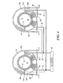
- the inventive method includes providing the paste 100, which consists of the admixture described above, applying the paste 100 to at least one of cut surfaces 102, 104 and to at least one of cut surfaces 106, 108 (FIG. 4) of the cores 22,24, adjoining the cut surfaces 102 and 104 with each other with the paste 100 therebetween, and similarly adjoining the cut surfaces 106 and 108 with each other with the paste therebetween, and removing the excess paste 100 which is squeezed out of the area between the mating surfaces in the course of moving the surfaces into substantial adjoinment.
- the paste is applied in sufficient quantities to fill all voids between the adjoining surfaces and eliminate all air gaps.
- rounded or spherical ferromagnetic particles While the use of rounded or spherical ferromagnetic particles is not necessary, it is preferred inasmuch as rounded particles readily squeeze out from between the cut ferrite surfaces 102 and 104, 106 and 108, to minimize the size of the paste-filled gap 110 which, in turn, maximizes the effective magnetic permeability of the core.
- a magnetic paste was prepared comprising 75% by weight - 325 mesh iron powder, and 25% by weight silicone vacuum thread lubricant. This was a stiff paste with maximized iron powder content.
- a magnetic paste was prepared comprising 85% by weight Fe3Si (iron, 3% silicon), spherical powder of particle size less than 20 microns, and 15% by weight high vacuum silicone grease.
- a magnetic paste was prepared comprising 75% by weight FeSiAl (iron, 9% silicon, 6% aluminum), spherical powder of particle size less than 10 microns, and 25% by weight silicone vacuum thread lubricant.
- a magnetic paste was prepared comprising 80% by weight FeSiAl (iron, 9% silicon, 6% aluminum), spherical powder of particle size less than 10 microns, and 20% by weight silicone vacuum thread lubricant.
- a magnetic paste was prepared comprising 85% by weight FeSiAl (iron, 9% silicon, 6% aluminum), spherical powder of particle size less than 10 microns, and 15% by weight silicone vacuum thread lubricant.
- a magnetic paste was prepared comprising 87% by weight FeSiAl (iron, 9% silicon, 6% aluminum), spherical powder of particle size less than 10 microns, and 13% by weight high temperature epoxy resin.
- the particles may alternatively comprise nickel or cobalt, or alloys thereof with alloying components, such as silicon, chromium, and the like.
Landscapes
- Engineering & Computer Science (AREA)
- Power Engineering (AREA)
- Physics & Mathematics (AREA)
- Plasma & Fusion (AREA)
- Electromagnetism (AREA)
- Discharge Lamps And Accessories Thereof (AREA)
- Ceramic Products (AREA)
- Soft Magnetic Materials (AREA)
Abstract
Description
| Results: Initial inductance (uH) | Inductance with Paste (uH) | |
| Average | 699 | 835 |
| Std. Deviation | 78.0 | 31.1 |
| Range | 561-789 | 775-873 |
| Percent inductance increase with paste: | 19.5 |
| Results: Initial | inductance (uH) | Inductance with Paste (uH) |
| Average | 728 | 857 |
| Std. Deviation | 57.2 | 26.3 |
| Range | 644-813 | 811-911 |
| Percent inductance increase with paste: | 17.7 |
| Results | : Initial inductance (uH) | Inductance with Paste (uH) |
| Average | 719 | 866 |
| Std. Deviation | 63.6 | 23.9 |
| Range | 647-829 | 824-898 |
| Percent inductance increase with paste: | 20.4 |
| Results: | Initial inductance (uH) | Inductance with Paste (uH) |
| Average | 727 | 886 |
| Std. Deviation | 64.4 | 17.9 |
| Range | 648-825 | 871-921 |
| Percent inductance increase with paste: | 21.9 |
| Results: Initial inductance (uH) Inductance with Paste (uH) | ||
| Average | 717 | 894 |
| Std. Deviation | 50.1 | 19.5 |
| Range | 663-804 | 859-915 |
| Percent inductance increase with paste: | 21.9 |
Claims (27)
- A method for joining cut surfaces of different portions of a ferrite core said method comprising the steps of:providing a high magnetic permeability paste comprising an admixture of a ferromagnetic material and a carrier therefor;apply the paste to the cut surface of at least one of the core portions; andabutting the cut surfaces and squeezing out and removing excess paste.
- The method in accordance with claim 1 wherein the carrier comprises a selected one of a group consisting of (i) silicone, (ii) high temperature epoxy resin, and (iii) a high temperature organic material.
- The method in accordance with claim 1 wherein the ferromagnetic material comprises ferromagnetic particles.
- The method in accordance with claim 1 wherein the ferromagnetic material comprises by weight about 70% - 95% of the admixture.
- The method in accordance with claim 1 wherein the ferromagnetic material comprises by weight about 75% - 87% of the admixture.
- The method in accordance with claim 3 wherein the ferromagnetic particles comprise a selected one of a group consisting of iron, nickel, cobalt, and alloys thereof.
- The method in accordance with claim 3 wherein the ferromagnetic particles comprise iron powder.
- The method in accordance with claim 7 wherein the iron powder is no greater than about - 325 mesh.
- The method in accordance with claim 3 wherein the particles are less than 30 microns in a longest dimension.
- The method in accordance with claim 3 wherein the particles are less than 10 microns in a longest dimension.
- The method in accordance with claim 3 wherein the particles are spherical and less than 30 microns in diameter.
- The method in accordance with claim 2 wherein the silicone carrier is a selected one of (i) a silicone resin, (ii) high vacuum silicone grease, and (iii) silicone vacuum thread lubricant.
- A high magnetic permeability paste for joining cut surfaces of different portions of a ferrite core for a fluorescent lamp, said paste comprising an admixture of:ferromagnetic material, anda carrier material therefor.
- The paste in accordance with claim 13 wherein said carrier material comprises a selected one of a group consisting of (i) silicone, (ii) high temperature epoxy resin, and (iii) a high temperature orgainic material.
- The paste in accordance with claim 13 wherein said ferromagnetic material comprises ferromagnetic particles.
- The paste in accordance with claim 13 wherein said ferromagnetic material comprises by weight about 70% - 95% of the admixture.
- The paste in accordance with claim 13 wherein said ferromagnetic material comprises by weight about 75% - 87% of the admixture.
- The paste in accordance with claim 15 wherein said ferromagnetic particles comprise iron powder and are less than 30 microns in a longest dimension.
- The paste in accordance with claim 15 wherein said ferromagnetic particles are spherical and less than 30 microns in diameter.
- The paste in accordance with claim 14 wherein the silicone carrier is a selected one of (i) a silicone resin, (ii) high vacuum silicone grease, and (iii) silicone vacuum thread lubricant.
- The paste in accordance with claim 13 wherein said ferromagnetic material comprises about 75% by weight iron powder of about - 325 mesh, and said carrier comprises about 25% by weight silicone vacuum threaded lubricant.
- The paste in accordance with claim 13 wherein said ferromagnetic material comprises about 85% by weight Fe3Si spherical powder of particle size less than 20 microns, and said carrier comprises about 15% by weight high vacuum silicone grease.
- The paste in accordance with claim 13 wherein said ferromagnetic material comprises about 75% by weight FeSiAl spherical powder of particle size less than 10 microns, and said carrier comprises about 25% by weight silicone vacuum thread lubricant.
- The paste in accordance with claim 13 wherein said ferromagnetic material comprises about 80% by weight FeSiAl spherical powder of particle size less than 10 microns, and said carrier comprises about 20% by weight silicone vacuum thread lubricant.
- The paste in accordance with claim 13 wherein said ferromagnetic material comprises about 85% by weight FeSiAl spherical powder of particle size less than 10 microns, and said carrier comprises about 15% by weight silicone vacuum thread lubricant.
- The paste in accordance with claim 13 wherein said ferromagnetic material comprises about 87% by weight FeSiAl spherical powder of particle size less than 10 microns, and said carrier comprises about 13% by weight high temperature epoxy resin.
- An electrodeless fluorescent lamp assembly comprising:a closed loop tubular lamp envelope enclosing a fill material for supporting a low pressure discharge;a transformer core disposed in proximity to said lamp envelope, said transformer core comprising a plurality of core sections;an input winding disposed on said transformer core for receiving radio frequency energy from a radio frequency source, the radio frequency energy producing the low pressure discharge in said lamp envelope; anda high magnetic permeability paste disposed between and joining cut surfaces of the core sections, said paste comprising an admixture of ferromagnetic material and a carrier therefor.
Applications Claiming Priority (2)
| Application Number | Priority Date | Filing Date | Title |
|---|---|---|---|
| US935112 | 2001-08-22 | ||
| US09/935,112 US20030062851A1 (en) | 2001-08-22 | 2001-08-22 | Method and paste for joiningcut surfaces of ferrite cores for fluorescent lamps |
Publications (2)
| Publication Number | Publication Date |
|---|---|
| EP1286371A2 true EP1286371A2 (en) | 2003-02-26 |
| EP1286371A3 EP1286371A3 (en) | 2003-10-29 |
Family
ID=25466597
Family Applications (1)
| Application Number | Title | Priority Date | Filing Date |
|---|---|---|---|
| EP02013722A Withdrawn EP1286371A3 (en) | 2001-08-22 | 2002-06-20 | Method and paste for joining cut surfaces of ferrite cores for fluorescent lamps |
Country Status (8)
| Country | Link |
|---|---|
| US (1) | US20030062851A1 (en) |
| EP (1) | EP1286371A3 (en) |
| JP (1) | JP2003141990A (en) |
| KR (1) | KR20030017373A (en) |
| CN (1) | CN1407598A (en) |
| CA (1) | CA2390771A1 (en) |
| NO (1) | NO20023939L (en) |
| TW (1) | TW569267B (en) |
Cited By (2)
| Publication number | Priority date | Publication date | Assignee | Title |
|---|---|---|---|---|
| WO2005071698A1 (en) * | 2004-01-23 | 2005-08-04 | Sturla Jonsson | Ferrite/polymer composition and process of production thereof |
| WO2009032377A1 (en) * | 2007-09-07 | 2009-03-12 | Vishay Dale Electronics, Inc. | High power inductors using a magnetic bias |
Families Citing this family (11)
| Publication number | Priority date | Publication date | Assignee | Title |
|---|---|---|---|---|
| WO2005074008A1 (en) * | 2004-01-18 | 2005-08-11 | Shanghai Hongyuan Lighting & Electrical Equipment Co., Ltd. | Compact electromagnetic induction lamp |
| US7088057B2 (en) * | 2004-09-13 | 2006-08-08 | International Business Machines Corporation | Apparatus, system, and method for inducing an electrical current for use by an electronic device |
| US20070132355A1 (en) * | 2005-12-09 | 2007-06-14 | Palmer Fred L | Low profile, low loss closed-loop electrodeless fluorescent lamp |
| JP4696962B2 (en) * | 2006-02-23 | 2011-06-08 | パナソニック電工株式会社 | Electrodeless discharge lamp device and lighting fixture |
| JP2008053186A (en) * | 2006-08-28 | 2008-03-06 | Matsushita Electric Works Ltd | Electrodeless discharge lamp and lighting fixture |
| US8618901B2 (en) * | 2007-05-16 | 2013-12-31 | Nec Corporation | Power acquisition device and power acquisition method |
| KR100868315B1 (en) * | 2007-06-01 | 2008-11-11 | 원광대학교산학협력단 | Electrodeless fluorescent lamp with ferrite core |
| CN101320672B (en) * | 2007-06-04 | 2010-09-22 | 任文华 | Induction non-polar light source |
| US7772753B2 (en) * | 2007-09-04 | 2010-08-10 | U.S. Energy Technologies, Inc. | Electrodeless lamp core assembly including coil bobbin and lamp envelope protector |
| CN101494156B (en) * | 2009-02-19 | 2010-06-09 | 上海宏源照明电器有限公司 | Electromagnetic induction lamp and air exhaust tube sheath |
| CN102280333A (en) * | 2011-05-30 | 2011-12-14 | 慕全文 | Dual magnetic core winding process for electrodeless lamp and manufacturing method of electrodeless lamp |
Family Cites Families (4)
| Publication number | Priority date | Publication date | Assignee | Title |
|---|---|---|---|---|
| JPH06166833A (en) * | 1992-11-30 | 1994-06-14 | Tokin Corp | Ferrite paste |
| JPH08148325A (en) * | 1994-11-24 | 1996-06-07 | Tokin Corp | Magnetic adhesive |
| US6175197B1 (en) * | 1997-10-14 | 2001-01-16 | Osram Sylvania Inc. | Electrodeless lamp having thermal bridge between transformer core and amalgam |
| EP1113464A3 (en) * | 1999-12-27 | 2002-05-15 | Alcatel USA Sourcing, L.P. | Microgapping process for magnetic cores |
-
2001
- 2001-08-22 US US09/935,112 patent/US20030062851A1/en not_active Abandoned
-
2002
- 2002-06-14 CA CA002390771A patent/CA2390771A1/en not_active Abandoned
- 2002-06-20 EP EP02013722A patent/EP1286371A3/en not_active Withdrawn
- 2002-07-26 TW TW091116711A patent/TW569267B/en active
- 2002-08-19 NO NO20023939A patent/NO20023939L/en not_active Application Discontinuation
- 2002-08-20 JP JP2002239646A patent/JP2003141990A/en active Pending
- 2002-08-21 KR KR1020020049412A patent/KR20030017373A/en not_active Withdrawn
- 2002-08-22 CN CN02130123A patent/CN1407598A/en active Pending
Cited By (4)
| Publication number | Priority date | Publication date | Assignee | Title |
|---|---|---|---|---|
| WO2005071698A1 (en) * | 2004-01-23 | 2005-08-04 | Sturla Jonsson | Ferrite/polymer composition and process of production thereof |
| WO2009032377A1 (en) * | 2007-09-07 | 2009-03-12 | Vishay Dale Electronics, Inc. | High power inductors using a magnetic bias |
| US8004379B2 (en) | 2007-09-07 | 2011-08-23 | Vishay Dale Electronics, Inc. | High powered inductors using a magnetic bias |
| EP2549492A1 (en) * | 2007-09-07 | 2013-01-23 | Vishay Dale Electronics, Inc. | High power inductors using a magnetic basis |
Also Published As
| Publication number | Publication date |
|---|---|
| NO20023939L (en) | 2003-02-24 |
| JP2003141990A (en) | 2003-05-16 |
| CA2390771A1 (en) | 2003-02-22 |
| TW569267B (en) | 2004-01-01 |
| NO20023939D0 (en) | 2002-08-19 |
| CN1407598A (en) | 2003-04-02 |
| US20030062851A1 (en) | 2003-04-03 |
| EP1286371A3 (en) | 2003-10-29 |
| KR20030017373A (en) | 2003-03-03 |
Similar Documents
| Publication | Publication Date | Title |
|---|---|---|
| US5834905A (en) | High intensity electrodeless low pressure light source driven by a transformer core arrangement | |
| US5886472A (en) | Electrodeless lamp having compensation loop for suppression of magnetic interference | |
| CA2241636C (en) | Electrodeless lamp having thermal bridge between transformer core and amalgam | |
| CA1149079A (en) | Compact fluorescent light source and method of excitation thereof | |
| US20030062851A1 (en) | Method and paste for joiningcut surfaces of ferrite cores for fluorescent lamps | |
| US7084562B2 (en) | Electrodeless discharge lamp | |
| JPS59180956A (en) | Electrodeless discharge lamp | |
| JP2002510123A (en) | High frequency inductive lamp and power oscillator | |
| US20020067129A1 (en) | Ferrite core for electrodeless flourescent lamp operating at 50-500 khz | |
| US4187447A (en) | Electrodeless fluorescent lamp with reduced spurious electromagnetic radiation | |
| CA2214660C (en) | Starting flag structure for tubular low pressure discharge lamps | |
| US6522085B2 (en) | High light output electrodeless fluorescent closed-loop lamp | |
| CA2185267C (en) | High intensity electrodeless low pressure light source | |
| JP2001143663A (en) | Electrodeless fluorescent lamp | |
| JP3680741B2 (en) | Electrodeless fluorescent lamp | |
| US20070132355A1 (en) | Low profile, low loss closed-loop electrodeless fluorescent lamp | |
| GB1597197A (en) | Core configuration for induction ionized lamps | |
| JPH04357661A (en) | Light source | |
| JPS585506B2 (en) | Electrodeless discharge device | |
| JPS60210828A (en) | Choke coil |
Legal Events
| Date | Code | Title | Description |
|---|---|---|---|
| PUAI | Public reference made under article 153(3) epc to a published international application that has entered the european phase |
Free format text: ORIGINAL CODE: 0009012 |
|
| AK | Designated contracting states |
Kind code of ref document: A2 Designated state(s): AT BE CH CY DE DK ES FI FR GB GR IE IT LI LU MC NL PT SE TR Designated state(s): AT BE CH CY DE DK ES FI FR GB GR IE IT LI LU MC NL PT SE TR |
|
| AX | Request for extension of the european patent |
Extension state: AL LT LV MK RO SI |
|
| PUAL | Search report despatched |
Free format text: ORIGINAL CODE: 0009013 |
|
| AK | Designated contracting states |
Kind code of ref document: A3 Designated state(s): AT BE CH CY DE DK ES FI FR GB GR IE IT LI LU MC NL PT SE TR |
|
| AX | Request for extension of the european patent |
Extension state: AL LT LV MK RO SI |
|
| RIC1 | Information provided on ipc code assigned before grant |
Ipc: 7H 01F 41/16 B Ipc: 7H 01F 27/255 B Ipc: 7H 01F 38/10 B Ipc: 7H 01F 27/26 B Ipc: 7H 01F 41/02 A |
|
| AKX | Designation fees paid | ||
| REG | Reference to a national code |
Ref country code: DE Ref legal event code: 8566 |
|
| STAA | Information on the status of an ep patent application or granted ep patent |
Free format text: STATUS: THE APPLICATION IS DEEMED TO BE WITHDRAWN |
|
| 18D | Application deemed to be withdrawn |
Effective date: 20040430 |