EP1286341A2 - Optical disk apparatus with flexible capacity by adjustment of recording density - Google Patents
Optical disk apparatus with flexible capacity by adjustment of recording density Download PDFInfo
- Publication number
- EP1286341A2 EP1286341A2 EP02017146A EP02017146A EP1286341A2 EP 1286341 A2 EP1286341 A2 EP 1286341A2 EP 02017146 A EP02017146 A EP 02017146A EP 02017146 A EP02017146 A EP 02017146A EP 1286341 A2 EP1286341 A2 EP 1286341A2
- Authority
- EP
- European Patent Office
- Prior art keywords
- optical disk
- recording
- contents information
- recording density
- information
- Prior art date
- Legal status (The legal status is an assumption and is not a legal conclusion. Google has not performed a legal analysis and makes no representation as to the accuracy of the status listed.)
- Withdrawn
Links
Images


Classifications
-
- G—PHYSICS
- G11—INFORMATION STORAGE
- G11B—INFORMATION STORAGE BASED ON RELATIVE MOVEMENT BETWEEN RECORD CARRIER AND TRANSDUCER
- G11B27/00—Editing; Indexing; Addressing; Timing or synchronising; Monitoring; Measuring tape travel
- G11B27/36—Monitoring, i.e. supervising the progress of recording or reproducing
-
- G—PHYSICS
- G11—INFORMATION STORAGE
- G11B—INFORMATION STORAGE BASED ON RELATIVE MOVEMENT BETWEEN RECORD CARRIER AND TRANSDUCER
- G11B20/00—Signal processing not specific to the method of recording or reproducing; Circuits therefor
- G11B20/10—Digital recording or reproducing
-
- G—PHYSICS
- G11—INFORMATION STORAGE
- G11B—INFORMATION STORAGE BASED ON RELATIVE MOVEMENT BETWEEN RECORD CARRIER AND TRANSDUCER
- G11B27/00—Editing; Indexing; Addressing; Timing or synchronising; Monitoring; Measuring tape travel
- G11B27/10—Indexing; Addressing; Timing or synchronising; Measuring tape travel
- G11B27/19—Indexing; Addressing; Timing or synchronising; Measuring tape travel by using information detectable on the record carrier
- G11B27/24—Indexing; Addressing; Timing or synchronising; Measuring tape travel by using information detectable on the record carrier by sensing features on the record carrier other than the transducing track ; sensing signals or marks recorded by another method than the main recording
-
- G—PHYSICS
- G11—INFORMATION STORAGE
- G11B—INFORMATION STORAGE BASED ON RELATIVE MOVEMENT BETWEEN RECORD CARRIER AND TRANSDUCER
- G11B20/00—Signal processing not specific to the method of recording or reproducing; Circuits therefor
- G11B20/00007—Time or data compression or expansion
- G11B2020/00079—Time or data compression or expansion the compression ratio or quality level being adapted to circumstances, e.g. to the available recording space
-
- G—PHYSICS
- G11—INFORMATION STORAGE
- G11B—INFORMATION STORAGE BASED ON RELATIVE MOVEMENT BETWEEN RECORD CARRIER AND TRANSDUCER
- G11B2220/00—Record carriers by type
- G11B2220/20—Disc-shaped record carriers
- G11B2220/21—Disc-shaped record carriers characterised in that the disc is of read-only, rewritable, or recordable type
- G11B2220/215—Recordable discs
- G11B2220/216—Rewritable discs
-
- G—PHYSICS
- G11—INFORMATION STORAGE
- G11B—INFORMATION STORAGE BASED ON RELATIVE MOVEMENT BETWEEN RECORD CARRIER AND TRANSDUCER
- G11B2220/00—Record carriers by type
- G11B2220/20—Disc-shaped record carriers
- G11B2220/21—Disc-shaped record carriers characterised in that the disc is of read-only, rewritable, or recordable type
- G11B2220/215—Recordable discs
- G11B2220/218—Write-once discs
-
- G—PHYSICS
- G11—INFORMATION STORAGE
- G11B—INFORMATION STORAGE BASED ON RELATIVE MOVEMENT BETWEEN RECORD CARRIER AND TRANSDUCER
- G11B2220/00—Record carriers by type
- G11B2220/20—Disc-shaped record carriers
- G11B2220/25—Disc-shaped record carriers characterised in that the disc is based on a specific recording technology
- G11B2220/2537—Optical discs
- G11B2220/2545—CDs
Definitions
- the present invention relates to an optical disk recording method and optical disk recording apparatus in which contents information is recorded in optical disks such as a compact disk-recordable (CD-R) and CD-rewritable (CD-RW).
- optical disks such as a compact disk-recordable (CD-R) and CD-rewritable (CD-RW).
- a guide groove called a pregroove is formed beforehand along a track in a disk manufacturing process.
- the pregroove wobbles (meanders), and a wobbling frequency thereof is detected and subjected to frequency modulation (FM) with absolute time information called Absolute Time in Pregroove (ATIP).
- FM frequency modulation
- ATP Absolute Time in Pregroove
- a wobbling signal is extracted from a photo signal of a light reflected back from the optical disk, the wobbling signal is FM-demodulated to decode ATIP information, and an absolute position along the track on the disk is detected by the decoded ATIP information. Moreover, the detected absolute position information is used to record the contents information in the optical disk.
- types of optical disks having different recording capacities have been distributed.
- CD-R a disk having a recording capacity of 650 MB (megabyte) and another disk having a recording capacity of 540 MB have been marketed.
- the distributed CD-R having the nominal recording capacity of 650 MB and the CD-R having the nominal recording capacity of 540 MB have the same physical length of the recordable track, but these two types of the disks are different from each other in the operating speed regulated according to the progression of the absolute time information of the ATIP information extracted from the disks. That is, the track length for use in recording the absolute time information of the ATIP information differs between these two types of the disks.
- the track length for use in storing the absolute time information of the ten minutes in the optical disk of 540 MB is larger than that of the optical disk of 650 MB. Therefore, the disks are different from each other in the recording density of the absolute time information. As a result, the recording capacity differs between these two types of the optical disks. That is, during the recording at a standard operation speed, the CD-R of 650 MB adopts a linear velocity of 1.2 m/s, the CD-R of 540 MB adopts a linear velocity of 1.4 m/s, and these linear velocities are referred to as rated linear velocities of the respective disks in the standard of the optical disk.
- the "linear velocity" in the standard actually has the same meaning as the recording density.
- the CD-R of 650 MB is different from the CD-R of 540 MB in the capacity to be recorded per unit track length.
- the CD-R of 650 MB is different from the CD-R of 540 MB in the recording density.
- the density of the CD-R of 650 MB is larger than that of the CD-R of 540 MB.
- the recording density obtained when the linear velocity is set to 1.2 m/s or 1.4 m/s during the recording at the standard operation speed is reciprocal to the linear velocity of 1.2 m/s or 1.4 m/s in the above-described standard.
- linear velocity will be used hereinafter for representing the recording density.
- the value 1.4 m/s denotes an information recording pitch at the standard operation speed and therefore used for indicating the recording density in recording the information at the linear velocity of 1.4 m/s.
- the value 1.2 m/s denotes an information recording pitch at the standard operation speed and is used for indicating the recording density in recording the information at the linear velocity of 1.2 m/s. Theoretically, the greater the value of the linear velocity, the smaller the recording density, because the linear velocity is inversely proportional to the recording density.
- the CD-R disks having different recording capacities have been manufactured and marketed, and a user sometimes carries out works necessary for selecting the CD-R having the recording capacity which meets the data amount to be recorded.
- the CD-R of 650 MB is selected in order to record music data for 74 minutes (CD-DA form: CD digital audio).
- the CD-R of 700 MB is selected to record music data for 80 minutes
- the CD-R of 540 MB is selected to record music data for 63 minutes or less.
- the disk selecting operation is troublesome, and further the user needs to prepare various types of CD-R disks beforehand.
- laborious works of purchasing the CD-R having the corresponding capacity has to be performed.
- the present invention has been developed in consideration of the above-described circumstances, and an object thereof is to provide an optical disk recording method and optical disk recording apparatus in which information can be preferably recorded in accordance with a capacity of data to be recorded and a capacity recordable in the optical disk.
- a method of recording contents information along a track of an optical disk of a writeable type comprises a volume detection step of detecting an actual volume of the contents information to be recorded into the optical disk, a capacity detection step of detecting a nominal capacity of the optical disk, which indicates a rated volume of information to be recorded at maximum, a density determination step of determining a recording density of the contents information based on the detected actual volume and the detected nominal capacity, and a record step of recording the contents information into the optical disk at the determined recording density such that the actual volume of the contents information can fit into the nominal capacity of the optical disk.
- the recording density can be changed based on the actual information volume to be recorded and the nominal information volume recordable in the optical disk (nominal recording capacity), and the information is recorded at the determined linear velocity such that the information can preferably be recorded in accordance with a relation between the actual information volume to be recorded and the nominal recordable information volume. For example, when the actual information volume to be recorded is small, the recording density is decreased, and thereby the recording with a higher quality level is possible. On the other hand, when the actual information volume to be recorded is large, the recording density is increased, and thereby data having a volume larger than the nominal recordable capacity can be recorded.
- a method of recording contents information along a track of an optical disk which is prerecorded with index information indicating progression of position or time along the track at a predetermined recording density.
- the inventive method comprises the steps of modulating an optical beam according to the contents information in response to a reference clock signal, irradiating the modulated optical beam along the track of the optical disk while rotating the optical disk at a variable rotation velocity so as to optically write the contents information into the optical disk, and adjusting either of a frequency of the reference clock signal and the rotation velocity of the optical disk so as to record the contents information at a recording density different from the predetermined recording density of the index information.
- the rotational velocity of the optical disk during the recording and/or the frequency for use in modulating the information to be recordediskontrolled hence the information can be recorded with the recording density other than the predetermined default recording density set in the optical disk.
- the recording density is decreased, and thereby the recording with a higher quality level is possible.
- the recording density is increased, and thereby the data having a volume larger than the nominal recordable information capacity can be recorded.
- a method of recording a volume of contents information along a track of an optical disk which is prerecorded with index information indicating progression of position or time along the track at a predetermined recording density to rate a capacity of the optical disk.
- the inventive method comprises the steps of determining a recording density based on an actual volume of the contents information to be recorded into the optical disk and the rated capacity of the optical disk, modulating an optical beam according to the contents information in response to a reference clock signal, irradiating the modulated optical beam along the track while rotating the optical disk at a variable rotation velocity so as to optically record the contents information, and adjusting either of a frequency of the reference clock signal and the rotation velocity of the optical disk when the determined recording density differs from the predetermined recording density for recording the contents information at the determined recording density such that the actual volume of the contents information can be compressed or expanded into the rated capacity of the optical disk.
- the rotational velocity of the optical disk and/or the frequency for use in modulating the information to be recordediskontrolled based on the actual information volume to be recorded and the nominal information volume recordable in the optical disk hence the recording density can be changed freely without sticking to the predetermined default recording density set in the optical disk.
- the information is recorded at the determined linear velocity such that the optimum recording is possible in accordance with the relation between the actual information volume to be recorded and the nominal recordable information volume. For example, when the actual information volume to be recorded is small, the recording density is decreased, and thereby the recording with a higher quality level is possible. On the other hand, when the actual information volume to be recorded is large, the recording density is increased, and thereby the data having a capacity larger than the nominal recordable information capacity can be recorded.
- an apparatus for recording contents information into a track of an optical disk of a writeable type comprises a volume detecting section that detects an actual volume of the contents information to be recorded into the optical disk, a capacity detecting section that detects a nominal capacity of the optical disk, which indicates a rated volume of information to be recorded at maximum, a clock setting section that sets a frequency of a reference clock signal according to the detected actual volume of the contents information and the detected nominal capacity of the optical disk, a modulating section that modulates an optical beam according to the contents information in response to the set frequency of the reference clock signal, and an irradiating section that irradiates the modulated optical beam onto the track so as to optically write the contents information into the optical disk such that the actual volume of the contents information can be filled into the nominal capacity of the optical disk.
- the frequency of the reference clock signal for use in modulating the contents information to be recorded can be changed based on the actual information volume to be recorded and the nominal information volume recordable in the optical disk.
- the recording density can be accordingly changed, and the information can be recorded at the optimum linear velocity so as to perform the optimum recording in accordance with the relation between the actual information volume to be recorded and the nominal recordable information volume.
- an apparatus for recording contents information into a track of an optical disk of a writeable type comprises a volume detecting section that detects an actual volume of the contents information to be recorded into the optical disk, a capacity detecting section that detects a nominal capacity of the optical disk, which indicates a rated volume of information to be recorded at maximum, a rotation control section that rotates the optical disk at an angular velocity controlled according to the detected actual volume of the contents information and the detected nominal capacity of the optical disk, a modulating section that modulates an optical beam according to the contents information, and an irradiating section that irradiates the modulated optical beam onto the track so as to optically write the contents information into the optical disk which is rotated at the controlled angular velocity such that the actual volume of the contents information can be filled into the nominal capacity of the optical disk.
- the angular driving speed of the optical disk as a recording object can be changed based on the actual information volume to be recorded and the nominal information volume recordable in the optical disk.
- the recording density can be changed accordingly, and the information can be recorded at the corresponding linear velocity so as to perform the optimum recording in accordance with the relation between the actual information volume to be recorded and the nominal recordable information volume.
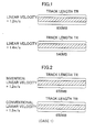
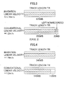
- FIGS. 1 to 4 are explanatory diagrams illustrating a principle of a method of recording data in an optical disk (hereinafter referred to as CD-R) according to one embodiment of the present invention.
- CD-R optical disk
- a basic principle of the recording method according to the present embodiment will be described.
- a plurality of types of disks having the same track length TR (track length of a region in which contents information is recorded) and having different recording capacities are distributed, such as a disk with a recording capacity of 650 MB (rated linear velocity of 1.2 m/s) and a disk with a recording capacity of 540 MB (rated linear velocity of 1.4 m/s).
- TR track length of a region in which contents information is recorded
- 540 MB rated linear velocity of 1.4 m/s
- the information is recorded at an optimum recording linear velocity without sticking to the rated linear velocity of the CD-R.
- the recording method based on the above-described basic principle will be described hereinafter in terms of three cases having the recording data amounts M of about 650 MB (Case 1), about 670 MB (Case 2), and about 540 MB (Case 3) for an object CD-R (upper optical disk of FIG. 1) which is set in the optical disk recording apparatus and which has the disk capacity N of about 650 MB (track length TR, rated linear velocity 1.2 m/s).
- the recording data amount M is 650 MB, that is, the disk capacity N agrees with the recording data amount M
- the recording is performed at the linear velocity identical to the rated linear velocity (1.2 m/s) of the CD-R as the recording object.
- a program area in which the contents data of the CD-R can be recorded is all used (oblique lines in the drawing indicate a recorded area), and data of 650 MB is recorded.
- the recording is carried out in the rated linear velocity.
- the linear velocity is set to 1.2 ⁇ 650/670 (about 1.16 m/s), not to the rated linear velocity (1.2 m/s) and the recording is performed.
- the recording data amount M (670 MB) can be recorded using all the program area (650 MB) of the CD-R.
- the conventional recording method using the rated linear velocity even when all the program area of the CD-R is used, the data for 20 MB cannot be recorded.
- the recording method according to the present embodiment when the information is recorded at the linear velocity lower than the rated linear velocity as described above, it is possible to record the data of 670 MB larger than the disk capacity N. Therefore, a recording error resulting from the over burn can be prevented from being generated, and the user does not have to perform a laborious operation of replacing the CD-R with a disk having a larger capacity.
- the linear velocity is set to 1.2 ⁇ 650/550 (about 1.4 m/s), not to the rated linear velocity (1.2 m/s) and the recording is performed.
- the data of 540 MB can be recorded using all the program area (650 MB) of the CD-R.
- the conventional recording method using the rated linear velocity all the data can be recorded using the region for 540 MB in the program area, but an unrecorded area for 110 MB remains.
- the data recorded in the CD-R can be reproduced without any problem.
- the recording data amount M is smaller than the disk capacity N, the information is recorded at the linear velocity (small recording density) higher than the rated linear velocity.
- the recording with the higher quality level is possible by raising the linear velocity.
- the disk capacity includes an extra region, the extra region is used and the recording density is lowered, so that data having a higher reproduction quality such as music data can preferably be recorded.
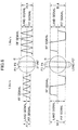
- the present inventor has obtained an eye pattern of an RF signal extracted from a reproduction signal during the recording at the linear velocity set to 1.4 m/s, and another eye pattern extracted from the reproduction signal during the recording at the linear velocity set to 1.2 m/s in the same CD-R, and the obtained result is shown in FIG. 5.
- T is a reference clock
- the eye pattern of the linear velocity of 1.4 m/s is represented more clearly than the eye pattern of 1.2 m/s.
- a jitter standard deviation of a recording pit length and recording land length from a standard length
- a result obtained by the recording at the linear velocity of 1.4 m/s is superior.
- the recording with a higher quality level is possible by the reduction of the recording density (the recording at the higher linear velocity of 1.4 m/s rather than 1.2 m/s).
- Such a dimensional relation between the pit length and the spot diameter R is caused by the above-described sizes of the amplitudes A 1.4 and A 1.2.
- the pit length of a pit P3 shown by a solid line in the drawing
- that of a pit P4 shown by a one-dot chain line in the drawing
- the recording density is decreased (the linear velocity is raised), the recording with a higher quality level is apparently performed. This is noticeable in the recording method according to the present embodiment.
- the recording data amount M is smaller than the disk capacity N as described above, that is, when there is an extra disk capacity N, the extra region is used to record the information at the linear velocity higher than the rated linear velocity.
- a linear velocity LT for the recording is obtained by the following equation, the linear velocity is set to the obtained LT in principal, and the recording is performed.
- LT L ⁇ N/M
- the recording data can all be recorded in the CD-R.
- the recording data amount M is smaller than the disk capacity N, the extra region of the disk capacity N is used, and the recording with a higher quality level is possible. That is, according to the recording method of the present embodiment, the information can be recorded at an optimum linear velocity in accordance with the disk capacity N and recording data amount M without sticking to the rated linear velocity of the disk.
- N/M is described instead of M/N described in the claims, but this means that the great value of the "linear velocity" used in the specification indicates the small value of the "recording density".
- optical disk recording method according to the present embodiment has been described above, and an optical disk recording apparatus for carrying out the inventive optical disk recording method will be described hereinafter.
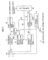
- FIG. 7 is a block diagram showing the constitution of an optical disk recording apparatus 100 according to one embodiment of the present invention, and the optical disk recording apparatus 100 is connected to a host computer (not shown) and used.
- the optical disk recording apparatus 100 includes a spindle motor 11, optical pickup 12, recording strategy circuit 13, EFM modulation unit 14, modulation clock generation circuit 15, divider 16, wobble signal extraction unit 17, ATIP demodulation unit 18, spindle controller 19, control unit 20, crystal oscillator 21, and changeover switch 22.
- the spindle motor 11 is a motor for rotationally driving an optical disk (CD-R in the present embodiment) as an object in which data is recorded.
- the optical pickup (irradiating means) 12 has an optical system including a laser diode, lens, mirror, and the like, and a return light receiving element. To record the data in the CD-R 101, the optical pickup irradiates a track of the CD-R 101 with a laser beam, receives a return light from the CD-R 101, and outputs an RF signal subjected to an eight-to-fourteen modulation (EFM) as a light receiving signal to the wobble signal extraction unit 17 via an RF amplifier (not shown).
- EFM eight-to-fourteen modulation
- the wobble signal extraction unit 17 extracts a wobble signal from the RF signal supplied from the optical pickup 12 via the RF amplifier and subjected to the EFM, and outputs the extracted wobble signal to the ATIP demodulation unit 18. As described above, a pregroove is formed along the track in the CD-R 101. Moreover, the pregroove wobbles, and the wobble signal extraction unit 17 extracts a wobbling signal WB as a component resulting from the wobbling from the RF signal supplied from the optical pickup 12.
- the ATIP demodulation unit 18 demodulates the wobbling signal WB extracted by the wobble signal extraction unit 17, and extracts an ATIP signal AP and bi-phase clock BC.
- the ATIP demodulation unit 18 outputs the demodulated bi-phase clock BC to the spindle controller 19, and outputs the demodulated ATIP signal AP to the changeover switch 22 and control unit 20.
- the spindle controller 19 uses the bi-phase clock BC supplied from the ATIP demodulation unit 18, and a clock signal CK supplied from the crystal oscillator 21 and having a predetermined frequency to drive the spindle motor 11. More concretely, the spindle controller 19 has a phase comparator and motor driver.
- the bi-phase clock BC is inputted into one input end of the phase comparator, and a signal obtained by dividing the clock signal CK at a predetermined dividing ratio is inputted into the other input end.
- an error signal is outputted to the motor driver from the phase comparator in accordance with a phase difference of both inputs, and the motor driver drives the spindle motor 11 in accordance with the error signal.
- the spindle controller 19 drives the spindle motor 11 in this manner, the spindle motor 11 can rotate the CD-R 101 so as to maintain a linear velocity of the track relative to the beam spot constant regardless of the recording position of the CD-R 101. That is, a constant linear velocity (CLV) driving is possible.
- CLV constant linear velocity
- the spindle controller 19 carries out spindle servo so as to set the frequency of the wobbling signal WB to 22.05 kHz, and the frequency of the bi-phase clock BC to 6.3 kHz.
- the spindle motor 11 is driven so that the recording is performed at a linear velocity of 1.2 m/s, that is, the linear velocity agreeing with the rated linear velocity of the CD-R 101.
- the frequencies of the wobbling signal WB, bi-phase clock BC, and ATIP signal AP have values double or four times the above-described numeric values.
- the ATIP signal AP from the ATIP demodulation unit 18 is supplied to the modulation clock generation circuit 15 via the changeover switch 22, and is used in generating a clock signal for modulation in the EFM modulation unit 14.
- the changeover switch 22 is connected so that the clock signal CK from the crystal oscillator 21 is supplied to the modulation clock generation circuit 15.
- the control unit (frequency setting means) 20 is constituted of a central processing unit (CPU), read only memory (ROM), random access memory (RAM), and the like, and all components of the optical disk recording apparatus 100 are controlled according to a program stored in the ROM so that a recording processing is executed.
- the control unit 20 is constituted to perform the following characteristic control so that the recording is performed at an optimum linear velocity in accordance with the recording data amount M and the disk capacity N.
- the control unit 20 recognizes the recording position by the optical pickup 12 based on the ATIP signal AP supplied from the ATIP demodulation unit 18, reads out ATIP special information and the like, recognizes a maximum lead-out start possible time (the last possible start position of the lead-out area in ATIP time code) of the CD-R 101 indicated in the ATIP special information, and detects the disk capacity N as the data amount recordable in the CD-R 101 based on the recognized maximum lead-out start time.
- the CD-R 101 is a disk having a rated linear velocity of 1.2 m/s
- the CD-R 101 can be detected to be a disk having a recording capacity of 650 MB from the maximum lead-out start possible time indicated in the ATIP special information.
- the control unit 20 supplies a control signal SB for setting the dividing ratio of the divider in the modulation clock generation circuit 15 described later based on the detected recording capacity of the CD-R 101 (hereinafter referred to as a disk capacity) and the actual volume of the data to be recorded supplied from the host computer (hereinafter referred to as the recording data amount). That is, the control unit 20 derives the dividing ratio of the divider in the modulation clock generation circuit 15 based on the disk capacity of the CD-R 101 and the recording data amount, and outputs the control signal SB for setting the derived dividing ratio to the modulation clock generation circuit 15.
- the modulation clock generation circuit 15 uses the control signal SB supplied from the control unit 20 and the clock signal CK having a predetermined period supplied from the crystal oscillator 21, generates a modulating clock signal MCK for use in the EFM modulation of the recording data in the EFM modulation unit 14, and outputs the signal to the divider 16.
- the modulating clock signal MCK is divided into 1/K (fixed value) by the divider 16, and the divided modulating clock signal MCK' is supplied to the EFM modulation unit 14 and used in the EFM modulation of the recording data.
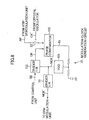
- the modulation clock generation circuit 15 has a phase comparator 150, voltage controlled oscillator (VCO) 151, and divider 152.
- VCO voltage controlled oscillator
- a signal is inputted into one input end of the phase comparator 150 in accordance with a connection state of the changeover switch 22.
- the changeover switch 22 is connected to a crystal oscillator 21 side during the recording in a CLV system, and the changeover switch 22 is connected to the ATIP demodulation unit 18 during the recording in a CAV system.
- the recording in the CLV system is described as an example, and a clock signal CK' obtained by dividing the clock signal CK supplied from the crystal oscillator 21 with the predetermined dividing ratio is inputted into one input end of the phase comparator 150.
- the frequency of the clock signal CK' supplied to one input end of the phase comparator 150 is 6.3 kHz.
- the frequency is 12.6 kHz at the double operation speed, and 25.2 kHz at the four-fold operation speed, and the frequency also increases in proportion to the multiple operation speed.
- a clock signal CN outputted from the divider 152 is supplied to the other input end of the phase comparator 150.
- the dividing ratio of the divider 152 can optionally be varied, and the dividing ratio (1/B) is set in accordance with the control signal SB supplied from the above-described control unit 20 (see FIG. 7). Therefore, the clock signal CN obtained by dividing the modulating clock signal MCK outputted from the voltage controlled oscillator 151 at (1/B) is supplied to the other input end of the phase comparator 150.
- the phase comparator 150 outputs a phase error signal IG of the clock signal CN and clock signal CK' (6.3 kHz at the standard operation speed) to the voltage controlled oscillator 151.
- the voltage controlled oscillator 151 is driven by the phase error signal IG. That is, an oscillation frequency of the voltage controlled oscillator 151 is controlled so that the phase of the clock signal CN outputted from the divider 152 agrees with the phase of the clock signal CK'.
- a divided modulating clock signal MCK' is supplied as a reference clock signal for modulation to the EFM modulation unit 14 (see FIG. 7).
- the modulation clock generation circuit 15 controls the frequency of the modulating clock signal MCK outputted to the EFM modulation unit 14 via the divider 16 in accordance with the control signal SB supplied from the control unit 20 shown in FIG. 7.
- the frequency of the reference clock signal for modulation supplied to the EFM modulation unit 14 is set under the control of the control unit 20 based on the recording data amount M to be recorded and the recordable disk capacity N. Additionally, details concerning the dividing ratio and the like of the divider 152 set by the control signal SB will be described later.
- the EFM modulation unit 14 subjects the data to be recorded supplied from the host computer (not shown) to EFM modulation using the modulating clock signal MCK' supplied from the modulation clock generation circuit 15 via the divider 16 as a reference clock (so-called 1T clock), and outputs an EFM-modulated signal to the recording strategy circuit 13.
- the recording strategy circuit 13 subjects the EFM signal supplied from the EFM modulation unit 14 to a time axis correction processing and the like, and outputs the signal to a laser driver (not shown).
- the laser driver drives the laser diode of the optical pickup 12, and the CD-R 101 is irradiated with the laser beam corresponding to the data to be recorded supplied from the host computer.
- the spindle motor 11 for driving the CD-R 101 is controlled so as to rotate the CD-R 101 at the speed following the rated linear velocity similarly as the conventional recording apparatus.
- the reference clock for use in the EFM modulation by the EFM modulation unit 14 is changed in accordance with the relation between the recording data amount M and the disk capacity N, and the effective linear velocity of the CD-R 101 or the recording density is changed to an optimum value in accordance with the relation between the disk capacity N and the recording data amount M as illustrated in the above-described three cases.
- the linear velocity is appropriately changed in accordance with the relation between the disk capacity N and the recording data amount M for the recording.
- the control unit 20 controls and sets the dividing ratio (1/B) of the divider 152 of the phase comparator 150 in accordance with the relation between the disk capacity N and the recording data amount M.
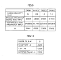
- the above-described three cases that is, the recording data amounts M of about 650 MB (Case 1), about 670 MB (Case 2), and about 540 MB (Case 3), and the recording data amount M of 500 MB (Case 4) are used as examples, while the CD-R set in the optical disk recording apparatus has a nominal disk capacity N of about 650 MB (rated linear velocity of 1.2 m/s). These examples are described using concrete numeric values.
- the recording data amount M is 650 MB, that is, when the disk capacity N meets the recording data amount M, similarly as the conventional optical disk recording apparatus, the recording is performed at the linear velocity identical to the rated linear velocity (1.2 m/s) of the CD-R as the recording object.
- the frequency of the modulating clock signal MCK' for use in the modulation of the EFM modulation unit 14 is 4.3218 MHz, and the frequency of the clock signal CK' is 6.3 kHz.
- the clock signal CK' of 4.3218 MHz is supplied to the EFM modulation unit 14. Therefore, in Case 1, the control unit 20 outputs the control signal SB such that the dividing ratio of the divider 152 is set to 1/43904.
- the recording data amount M is 670 MB
- the recording data amount M is 540 MB
- the linear velocity is set to be higher than the rated linear velocity (1.2 m/s) and the recording is performed.
- the linear velocity determined as described above is higher than 1.4 m/s
- the linear velocity is set to 1.4 m/s and the recording is performed. Therefore, the value B for setting the dividing ratio of the divider 152 is identical to the value (37632) of Case 3 described above, and the control unit 20 outputs the control signal SB such that the dividing ratio of the divider 152 is set to 1/37632.
- the control unit 20 in the optical disk recording apparatus 100 generates the control signal SB for setting the dividing ratio of the divider 152 from the relation between the disk capacity N and the recording data amount M as described above.
- the control signal SB is outputted and the dividing ratio of the divider 152 is set, and when the recording data amount M is larger than the disk capacity N, all the recording data can be compressed and filled in the CD-R.
- the recording data amount M is smaller than the disk capacity N, the extra region of the disk capacity N is used and the recording with a higher quality level is possible by expanding the data and filling the tracks. Therefore, according to the optical disk recording apparatus 100, the data can be recorded at the optimum linear velocity in accordance with the relation between the disk capacity N and the recording data amount M without sticking to the rated linear velocity of the disk.
- the recording is basically performed at a linear velocity determined by LxN/M, assuming that the disk capacity is N, the recording data amount is M, and the rated linear velocity of the disk is L.
- the tentative linear velocity LT obtained by the above-described L ⁇ N/M is used as a reference, the closest linear velocity is selected, and the recording may be performed at the selected linear velocity.
- N/M is described although M/N is described in the claims. This is because the large value of the "linear velocity" used in the specification means the small value of the "recording density".
- a table shown in FIG. 10 may be stored in the ROM of the control unit 20 of the optical disk recording apparatus 100.
- a range of values which can be taken by the disk capacity N/recording data amount M, and the values B for setting the dividing ratio of the divider 152 are associated with each other and stored in the memory.
- N/M is computed from the disk capacity N and recording data amount M obtained by the control unit 20, and the value B associated with the range which agrees with the value of the N/M is selected.
- the recording is performed at the linear velocity of about 1.16 m/s.
- the recording is performed at the linear velocity of 1.4 m/s.
- the optical disk recording apparatus 100 controls the spindle motor 11 to drive the CD-R 101 at the speed following the rated linear velocity similarly as the conventional recording apparatus.
- the linear velocity (recording density) is effectively changed.
- the method may include: using the signal of the frequency following the rated linear velocity in the reference clock for use in the EFM modulation by the EFM modulation unit 14 (the same as the conventional recording apparatus), and rotating the CD-R 101 at the variable speed different from the rated linear velocity of the CD-R 101, so that the linear velocity may be changed.
- the control unit (driving control means) 20 may control the spindle controller 19 in accordance with the relation between the disk capacity N and the recording data amount M.
- FIG. 11 shows the constitution of the spindle controller 19.
- the spindle controller 19 has a phase comparator 191 and divider 192.
- the dividing ratio of the divider 192 is set by a control signal SB' supplied from the control unit 20, and the clock signal CK supplied from the crystal oscillator 21 is divided at the set dividing ratio.
- the divided clock signal CK" is inputted into one input end of the phase comparator 191.
- the bi-phase clock BC supplied from the ATIP demodulation unit 18 is inputted into the other input end of the phase comparator 191.
- the phase comparator 191 outputs the error signal to the motor driver (not shown) in accordance with the phase difference of both inputs, and the motor driver drives the spindle motor 11 in accordance with the error signal. That is, when the dividing ratio of the divider 192 is changed, the rotational velocity of the CD-R 101 by the spindle motor 11 can be changed.
- control unit 20 when the control unit 20 outputs the control signal SB' for rotating and driving the CD-R 101 so as to perform the recording at the linear velocity in accordance with the relation between the disk capacity N and the recording data amount M, similarly as the above-described optical disk recording apparatus 100, the recording can be performed at the optimum linear velocity in accordance with the relation between the disk capacity N and the recording data amount M.
- the CPU of the control unit 20 executes a recording process including a processing for setting the linear velocity in accordance with the relation between the disk capacity N and the recording data amount M according to the program stored beforehand in the ROM, but a control circuit constituted by a dedicated hardware may perform the process similarly as described above.
- various recording mediums such as a CD-ROM and floppy disk in which the program for allowing a computer to realize the above-described processing may be presented to the user, or the program may be presented to the user via transmission mediums such as Internet.
- the program for performing the processing installed in an electrically erasable and programmable ROM (EEPROM) of the conventional optical disk recording apparatus via the recording medium or the transmission medium may be updated so that the processing similar to that of the above-described optical disk recording apparatus 100 is performed.
- EEPROM electrically erasable and programmable ROM
- an optimum recording can be performed in accordance with a volume of data to be recorded and a capacity recordable in an optical disk. It should be noted that objects and advantages of the invention may be attained by means of compatible combination(s) particularly pointed out in the items of the following summary of the invention.
Landscapes
- Engineering & Computer Science (AREA)
- Signal Processing (AREA)
- Optical Recording Or Reproduction (AREA)
- Signal Processing For Digital Recording And Reproducing (AREA)
Abstract
Description
For example, the track length for use in storing the absolute time information of the ten minutes in the optical disk of 540 MB is larger than that of the optical disk of 650 MB. Therefore, the disks are different from each other in the recording density of the absolute time information. As a result, the recording capacity differs between these two types of the optical disks. That is, during the recording at a standard operation speed, the CD-R of 650 MB adopts a linear velocity of 1.2 m/s, the CD-R of 540 MB adopts a linear velocity of 1.4 m/s, and these linear velocities are referred to as rated linear velocities of the respective disks in the standard of the optical disk. Additionally, the "linear velocity" in the standard actually has the same meaning as the recording density. For example, the CD-R of 650 MB is different from the CD-R of 540 MB in the capacity to be recorded per unit track length. Namely, the CD-R of 650 MB is different from the CD-R of 540 MB in the recording density. The density of the CD-R of 650 MB is larger than that of the CD-R of 540 MB. The recording density obtained when the linear velocity is set to 1.2 m/s or 1.4 m/s during the recording at the standard operation speed is reciprocal to the linear velocity of 1.2 m/s or 1.4 m/s in the above-described standard. Therefore, the term "linear velocity" will be used hereinafter for representing the recording density. The value 1.4 m/s denotes an information recording pitch at the standard operation speed and therefore used for indicating the recording density in recording the information at the linear velocity of 1.4 m/s. In similar manner, the value 1.2 m/s denotes an information recording pitch at the standard operation speed and is used for indicating the recording density in recording the information at the linear velocity of 1.2 m/s. Theoretically, the greater the value of the linear velocity, the smaller the recording density, because the linear velocity is inversely proportional to the recording density.
In the recording method according to the present embodiment, in accordance with the recordable capacity (hereinafter referred to as a disk capacity N) of the CD-R set in an optical disk recording apparatus, and a data amount to be recorded (hereinafter referred to as a recording data amount M), the information is recorded at an optimum recording linear velocity without sticking to the rated linear velocity of the CD-R.
Additionally, in the above equation, N/M is described instead of M/N described in the claims, but this means that the great value of the "linear velocity" used in the specification indicates the small value of the "recording density". When the recording density is used as a unit instead of the "linear velocity", the equation is represented by LT = L×M/N.
More concretely, the
As a result, similarly as the conventional optical disk recording apparatus, the clock signal CK' of 4.3218 MHz is supplied to the
Additionally, in the above equation, N/M is described although M/N is described in the claims. This is because the large value of the "linear velocity" used in the specification means the small value of the "recording density". When the recording density is used as the unit instead of the "linear velocity", the above equation is represented as LT = L×M/N.
The dividing ratio of the
It should be noted that objects and advantages of the invention may be attained by means of compatible combination(s) particularly pointed out in the items of the following summary of the invention.
Claims (12)
- A method of recording contents information along a track of an optical disk of a writeable type, the method comprising:a volume detection step of detecting an actual volume of the contents information to be recorded into the optical disk;a capacity detection step of detecting a nominal capacity of the optical disk, which indicates a rated volume of information to be recorded at maximum;a density determination step of determining a recording density of the contents information based on the detected actual volume and the detected nominal capacity; anda record step of recording the contents information into the optical disk at the determined recording density such that the actual volume of the contents information can fit into the nominal capacity of the optical disk.
- The method according to claim 1, wherein the optical disk is prerecorded with index information indicating progression of position or time along the track at a predetermined recording density, and wherein the record step is carried out when the determined recording density differs from the predetermined recording density for recording the contents information at the determined recording density rather than the predetermined recording density,
and/ or wherein preferably the density determination step is carried out when the actual volume is greater than the nominal capacity for determining the recording density of the contents information greater than the predetermined recording density of the index information,
and/ or wherein preferably the density determination step determines the recording density based on a value LxM/N, where M denotes the actual volume, N denotes the nominal capacity and L denotes the predetermined recording density,
and/ or wherein preferably the density determination step is carried out when the value LxM/N is smaller than a lower limit value for determining the recording density to the lower limit value. - The method according to claim 1, wherein the capacity detection step is carried out when the optical disk comprises a CD-R or CD-RW formed according to a standard of Orange Book for reading the last possible start position of a lead-out area in ATIP time code indicated in Special Information of ATIP prerecorded in the optical disk and for determining the nominal capacity of the optical disk based on the last possible start position of the lead-out area.
- A method of recording contents information along a track of an optical disk which is prerecorded with index information indicating progression of position or time along the track at a predetermined recording density, the method comprising the steps of:modulating an optical beam according to the contents information in response to a reference clock signal;irradiating the modulated optical beam along the track of the optical disk while rotating the optical disk at a variable rotation velocity so as to optically write the contents information into the optical disk; andadjusting either of a frequency of the reference clock signal and the rotation velocity of the optical disk so as to record the contents information at a recording density different from the predetermined recording density of the index information.
- A method of recording a volume of contents information along a track of an optical disk which is prerecorded with index information indicating progression of position or time along the track at a predetermined recording density to rate a capacity of the optical disk, the method comprising the steps of:determining a recording density based on an actual volume of the contents information to be recorded into the optical disk and the rated capacity of the optical disk;modulating an optical beam according to the contents information in response to a reference clock signal;irradiating the modulated optical beam along the track while rotating the optical disk at a variable rotation velocity so as to optically record the contents information; andadjusting either of a frequency of the reference clock signal and the rotation velocity of the optical disk when the determined recording density differs from the predetermined recording density for recording the contents information at the determined recording density such that the actual volume of the contents information can be compressed or expanded into the rated capacity of the optical disk.
- An apparatus for recording contents information into a track of an optical disk of a writeable type, comprising:a volume detecting section that detects an actual volume of the contents information to be recorded into the optical disk;a capacity detecting section that detects a nominal capacity of the optical disk, which indicates a rated volume of information to be recorded at maximum;a clock setting section that sets a frequency of a reference clock signal according to the detected actual volume of the contents information and the detected nominal capacity of the optical disk;a modulating section that modulates an optical beam according to the contents information in response to the set frequency of the reference clock signal; andan irradiating section that irradiates the modulated optical beam onto the track so as to optically write the contents information into the optical disk such that the actual volume of the contents information can be filled into the nominal capacity of the optical disk.
- The apparatus according to claim 6, wherein the optical disk is prerecorded with index information indicating progression of position or time along the track at a predetermined recording density, and the clock setting section sets the frequency of the reference clock signal so as to enable the recording of the contents information at an adjusted recording density different from the predetermined recording density,
and/ or wherein preferably the clock setting section sets the frequency of the reference clock signal so as to enable the recording of the contents information at the adjusted recording density represented by a value L×M/N, where M denotes the actual volume, N denotes the nominal capacity and L denotes the predetermined recording density,
and/ or wherein preferably the clock setting section operates when the value L×M/N is smaller than a lower limit value for setting the frequency of the reference clock signal so as to enable the recording of the contents information at the adjusted recording density having the lower limit value. - An apparatus for recording contents information into a track of an optical disk of a writeable type, comprising:a volume detecting section that detects an actual volume of the contents information to be recorded into the optical disk;a capacity detecting section that detects a nominal capacity of the optical disk, which indicates a rated volume of information to be recorded at maximum;a rotation control section that rotates the optical disk at an angular velocity controlled according to the detected actual volume of the contents information and the detected nominal capacity of the optical disk;a modulating section that modulates an optical beam according to the contents information; andan irradiating section that irradiates the modulated optical beam onto the track so as to optically write the contents information into the optical disk which is rotated at the controlled angular velocity such that the actual volume of the contents information can be filled into the nominal capacity of the optical disk.
- The apparatus according to claim 8 , wherein the optical disk is prerecorded with index information indicating progression of position or time along the track at a predetermined recording density, and the rotation control section controls the angular velocity of the optical disk so as to enable the recording of the contents information at an adjusted recording density different from the predetermined recording density.
- A computer program executable by a CPU of an optical recording apparatus for recording contents information along a track of an optical disk of a writeable type, wherein the computer program comprises:a volume detection step of detecting an actual volume of the contents information to be recorded into the optical disk;a capacity detection step of detecting a nominal capacity of the optical disk, which indicates a rated volume of information to be recorded at maximum;a density determination step of determining a recording density of the contents information based on the detected actual volume and the detected nominal capacity; anda record step of recording the contents information into the optical disk at the determined recording density such that the actual volume of the contents information can fit into the nominal capacity of the optical disk.
- A computer program executable by a CPU of an optical recording apparatus for recording contents information along a track of an optical disk which is prerecorded with index information indicating progression of position or time along the track at a predetermined recording density, wherein the computer program comprises the steps of:modulating an optical beam according to the contents information in response to a reference clock signal;irradiating the modulated optical beam along the track of the optical disk while rotating the optical disk at a variable rotation velocity so as to optically write the contents information into the optical disk; andadjusting either of a frequency of the reference clock signal and the rotation velocity of the optical disk so as to record the contents information at a recording density different from the predetermined recording density of the index information.
- A computer program executable by a CPU of an optical recording apparatus for recording a volume of contents information along a track of an optical disk which is prerecorded with index information indicating progression of position or time along the track at a predetermined recording density to rate a capacity of the optical disk, wherein the computer program comprises the steps of:determining a recording density based on an actual volume of the contents information to be recorded into the optical disk and the rated capacity of the optical disk;modulating an optical beam according to the contents information in response to a reference clock signal;irradiating the modulated optical beam along the track while rotating the optical disk at a variable rotation velocity so as to optically record the contents information; andadjusting either of a frequency of the reference clock signal and the rotation velocity of the optical disk when the determined recording density differs from the predetermined recording density for recording the contents information at the determined recording density such that the actual volume of the contents information can be compressed or expanded into the rated capacity of the optical disk.
Applications Claiming Priority (2)
| Application Number | Priority Date | Filing Date | Title |
|---|---|---|---|
| JP2001230392A JP3711902B2 (en) | 2001-07-30 | 2001-07-30 | Recording density determination method in optical disk recording |
| JP2001230392 | 2001-07-30 |
Publications (2)
| Publication Number | Publication Date |
|---|---|
| EP1286341A2 true EP1286341A2 (en) | 2003-02-26 |
| EP1286341A3 EP1286341A3 (en) | 2003-12-17 |
Family
ID=19062616
Family Applications (1)
| Application Number | Title | Priority Date | Filing Date |
|---|---|---|---|
| EP02017146A Withdrawn EP1286341A3 (en) | 2001-07-30 | 2002-07-30 | Optical disk apparatus with flexible capacity by adjustment of recording density |
Country Status (4)
| Country | Link |
|---|---|
| US (2) | US7046597B2 (en) |
| EP (1) | EP1286341A3 (en) |
| JP (1) | JP3711902B2 (en) |
| CN (1) | CN1188843C (en) |
Families Citing this family (26)
| Publication number | Priority date | Publication date | Assignee | Title |
|---|---|---|---|---|
| US7200080B2 (en) * | 2002-01-16 | 2007-04-03 | Yamaha Corporation | Optical disk recorder with reproduction quality control |
| TWI224774B (en) * | 2002-05-07 | 2004-12-01 | Benq Corp | Determination of maximum storage capacity of optical information record medium |
| DK1652178T3 (en) | 2003-07-07 | 2009-08-24 | Lg Electronics Inc | Recording medium, method of configuring control information thereof, method of recording or reproducing data using the same and apparatus therefor |
| CA2474995C (en) * | 2003-07-07 | 2011-11-22 | Lg Electronics Inc. | Recording medium, method of configuring control information thereof, recording and/or reproducing method using the same, and apparatus thereof |
| KR100953637B1 (en) * | 2003-07-07 | 2010-04-20 | 엘지전자 주식회사 | Optical Disc and Disc Information Recording Method |
| US7564760B2 (en) | 2003-07-09 | 2009-07-21 | Lg Electronics, Inc. | Recording medium, method of configuring disc control information thereof, recording and reproducing method using the same, and apparatus thereof |
| KR101024904B1 (en) * | 2003-08-14 | 2011-03-31 | 엘지전자 주식회사 | Recording medium, recording method, recording device and recording / reproducing system |
| WO2005017889A1 (en) * | 2003-08-14 | 2005-02-24 | Lg Electronics Inc. | Recording medium, method of configuring control information thereof, recording and/or reproducing method using the same, and apparatus thereof |
| WO2005017879A2 (en) * | 2003-08-14 | 2005-02-24 | Lg Electronics Inc. | Recording medium, method of configuring control information thereof, recording and reproducing method using the same, and apparatus thereof |
| ATE491203T1 (en) * | 2003-08-14 | 2010-12-15 | Lg Electronics Inc | RECORDING MEDIUM, CONFIGURATION METHOD FOR THE RELATED TAX INFORMATION, RECORDING AND PLAYBACK METHOD AND APPARATUS THEREOF |
| EP1751749B1 (en) * | 2004-05-13 | 2014-12-17 | LG Electronics Inc. | Recording medium, read/write method thereof and read/write apparatus thereof |
| KR101041809B1 (en) * | 2004-07-27 | 2011-06-17 | 엘지전자 주식회사 | Optical disc and optical disc control information composition method and optical disc recording and reproducing method and apparatus using same |
| JP3938175B2 (en) * | 2004-10-01 | 2007-06-27 | 船井電機株式会社 | Optical disc recording / reproducing apparatus |
| US20080117784A1 (en) * | 2004-11-26 | 2008-05-22 | Yoshimichi Nishio | Boundary Detection Apparatus, Boundary Detection Method, Boundary Detection Program, and Information Recording Medium |
| US7603530B1 (en) | 2005-05-05 | 2009-10-13 | Seagate Technology Llc | Methods and structure for dynamic multiple indirections in a dynamically mapped mass storage device |
| US7685360B1 (en) | 2005-05-05 | 2010-03-23 | Seagate Technology Llc | Methods and structure for dynamic appended metadata in a dynamically mapped mass storage device |
| US7653847B1 (en) | 2005-05-05 | 2010-01-26 | Seagate Technology Llc | Methods and structure for field flawscan in a dynamically mapped mass storage device |
| US7620772B1 (en) * | 2005-05-05 | 2009-11-17 | Seagate Technology, Llc | Methods and structure for dynamic data density in a dynamically mapped mass storage device |
| US7617358B1 (en) | 2005-05-05 | 2009-11-10 | Seagate Technology, Llc | Methods and structure for writing lead-in sequences for head stability in a dynamically mapped mass storage device |
| US7916421B1 (en) | 2005-05-05 | 2011-03-29 | Seagate Technology Llc | Methods and structure for recovery of write fault errors in a dynamically mapped mass storage device |
| US7752491B1 (en) | 2005-05-05 | 2010-07-06 | Seagate Technology Llc | Methods and structure for on-the-fly head depopulation in a dynamically mapped mass storage device |
| KR100701733B1 (en) * | 2005-10-11 | 2007-03-29 | 주식회사 히타치엘지 데이터 스토리지 코리아 | Optimal Light Strategies Detection Method for Optical Disc Devices |
| ATE481709T1 (en) * | 2006-06-20 | 2010-10-15 | Koninkl Philips Electronics Nv | DEVICES AND METHOD FOR DETERMINING THE CRITICAL SPEED OF AN OPTICAL DATA CARRIER, MONITORING THE STATE OF AN OPTICAL DATA RECEIVER AND GENERATING A REFERENCE SIGNAL |
| US8312310B2 (en) * | 2007-05-01 | 2012-11-13 | Canon Kabushiki Kaisha | Apparatus and method for changing clock frequency and modulation method based on current state |
| US7911724B2 (en) * | 2009-02-10 | 2011-03-22 | Seagate Technology Llc | Write synchronization phase calibration for storage media |
| US9047921B2 (en) * | 2009-11-19 | 2015-06-02 | HGST Netherlands B.V. | Adjusting recording density in a circumferential direction |
Family Cites Families (24)
| Publication number | Priority date | Publication date | Assignee | Title |
|---|---|---|---|---|
| GB2172767B (en) | 1985-01-31 | 1989-02-08 | Canon Kk | Image signal processing system |
| CA2017501C (en) * | 1989-05-26 | 1995-08-29 | Shigeo Terashima | Recording/reproducing device |
| US5825733A (en) | 1990-07-31 | 1998-10-20 | Sony Corporation | Optical disc recording apparatus for recording data at a disc rotational speed selected from a range of disc rotational speeds |
| JP3164162B2 (en) | 1991-10-24 | 2001-05-08 | キヤノン株式会社 | Information signal storage device and method thereof |
| JPH05282730A (en) | 1992-03-31 | 1993-10-29 | Sony Corp | Disk recording and reproducing device |
| JP3465272B2 (en) | 1992-08-28 | 2003-11-10 | ソニー株式会社 | Digital data recording device and recording method |
| US5572502A (en) * | 1993-09-28 | 1996-11-05 | Hitachi, Ltd. | Optical disk apparatus |
| US5671204A (en) * | 1994-05-25 | 1997-09-23 | Victor Company Of Japan, Ltd. | Variable transfer rate data reproduction apparatus |
| KR960705317A (en) | 1994-08-08 | 1996-10-09 | 이데이 노부유키 | Data recording method, data recording device, round disc shaped recording medium, computer system and data copy preventing method (Data recording method, data, recording apparatus, disk-shaped recording medlum, computer system and data copy preventing method) |
| JPH08167275A (en) | 1994-12-14 | 1996-06-25 | Sony Corp | Disk recorder |
| CA2169131C (en) | 1995-02-28 | 2004-08-10 | Fabrizio Caffarelli | Compact disc recording system and method |
| DE69725810T2 (en) * | 1996-08-30 | 2004-08-12 | Sharp K.K. | Disc-shaped recording medium and apparatus for recording and reproducing a disc |
| JPH10134517A (en) * | 1996-10-29 | 1998-05-22 | Mitsubishi Electric Corp | Format writing device and flexible disk |
| JPH11283291A (en) * | 1998-01-30 | 1999-10-15 | Fujitsu Ltd | Storage device, optical recording medium, and information recording method |
| US6137644A (en) * | 1998-05-19 | 2000-10-24 | International Business Machines Corporation | Method for adaptive formatting and track traversal in data storage devices |
| TWI222627B (en) | 1998-10-27 | 2004-10-21 | Hitachi Maxell | Information recording method and system, image compression/decompression system, system control method and monitoring system including a part or all of the method |
| JP2001014801A (en) | 1998-10-27 | 2001-01-19 | Hitachi Maxell Ltd | Information recording method and system, image compression / decompression system, system control method, and monitoring system having some or all of these |
| US6901039B1 (en) | 1999-04-15 | 2005-05-31 | Mitsumi Electric Co., Ltd. | Writable optical drive with dynamically variable linear velocity to prevent buffer under-run |
| EP1169700B1 (en) | 1999-04-15 | 2005-06-22 | Mitsumi Electric Co., Ltd. | Writable optical drive with dynamically variable linear velocity to prevent buffer under-run |
| EP1182649B1 (en) * | 1999-05-19 | 2006-10-04 | Mitsubishi Kagaku Media Co., Ltd. | Optical recording method and optical recording medium |
| US6411574B1 (en) * | 1999-09-14 | 2002-06-25 | Ritek Corporation | Coding method for high-capacity storage medium and the decoding means for the same |
| MY126056A (en) | 1999-09-29 | 2006-09-29 | Sony Corp | Data record medium, data recording and/or reproducing apparatus, and record medium determining method |
| JP2002025064A (en) | 2000-07-12 | 2002-01-25 | Sony Corp | Recording device, method and medium |
| JP2002343031A (en) | 2001-03-12 | 2002-11-29 | Sanyo Electric Co Ltd | Disk recording device and disk |
-
2001
- 2001-07-30 JP JP2001230392A patent/JP3711902B2/en not_active Expired - Fee Related
-
2002
- 2002-07-25 CN CNB021270171A patent/CN1188843C/en not_active Expired - Fee Related
- 2002-07-29 US US10/207,302 patent/US7046597B2/en not_active Expired - Fee Related
- 2002-07-30 EP EP02017146A patent/EP1286341A3/en not_active Withdrawn
-
2005
- 2005-11-14 US US11/273,489 patent/US7339863B2/en not_active Expired - Fee Related
Also Published As
| Publication number | Publication date |
|---|---|
| US20030021202A1 (en) | 2003-01-30 |
| US20060077821A1 (en) | 2006-04-13 |
| US7339863B2 (en) | 2008-03-04 |
| CN1188843C (en) | 2005-02-09 |
| CN1400589A (en) | 2003-03-05 |
| EP1286341A3 (en) | 2003-12-17 |
| JP2003045118A (en) | 2003-02-14 |
| JP3711902B2 (en) | 2005-11-02 |
| US7046597B2 (en) | 2006-05-16 |
Similar Documents
| Publication | Publication Date | Title |
|---|---|---|
| US7046597B2 (en) | Optical disk apparatus for recording information at a recording density proportional to the actual information volume and disk nominal capacity | |
| US7088667B2 (en) | Optical disc, optical disc recording/reproducing apparatus, and optical disc recording/reproducing method | |
| KR940002000B1 (en) | Optical disk recording/reproducing method | |
| US7012864B2 (en) | Optical disk recorder for writing data with variable density | |
| JP3496628B2 (en) | Optical disk recording method and optical disk recording device | |
| EP0642128B1 (en) | Recordable optical disk | |
| US8045438B2 (en) | High frequency modulation of a light beam in optical recording | |
| EP0642122B1 (en) | Method and system for recording information on an optical disk | |
| JP3845951B2 (en) | Disc-shaped recording medium, disc reproducing apparatus, and disc reproducing method | |
| JP2002025199A (en) | Recording device, recording medium, reproducing device, method of determining recording medium | |
| KR101094102B1 (en) | Recording medium, information recording apparatus, information recording method and information recording medium | |
| JP2537552B2 (en) | Optical disc player | |
| JP2559143B2 (en) | Optical disk recording device | |
| JP2003067929A (en) | Optical disk, optical disk recording device, method for controlling the optical disk recording device and program | |
| JP4079165B2 (en) | Recording density determination method in optical disk recording | |
| US7095689B2 (en) | Method and device for controlling the rotating speed of a spindle of an optical disk drive through a wobble signal, an EEFS signal and an ESFS signal | |
| JP4670895B2 (en) | Optical disk recording device | |
| JP4614259B2 (en) | Optical disc recording method and optical disc recording apparatus | |
| JP2002216350A (en) | Recording device | |
| JP2006019020A (en) | Optical disk recording method and optical disk recorder | |
| JP2004030893A (en) | Optical disk recording method and optical disk recording device | |
| JP2002216346A (en) | Disk drive device, address acquisition method | |
| JP2001243631A (en) | Optical disk recorder | |
| JP2004005984A (en) | Optical disk drive | |
| JP2002269750A (en) | Optical disk and recording method and device for the same |
Legal Events
| Date | Code | Title | Description |
|---|---|---|---|
| PUAI | Public reference made under article 153(3) epc to a published international application that has entered the european phase |
Free format text: ORIGINAL CODE: 0009012 |
|
| AK | Designated contracting states |
Kind code of ref document: A2 Designated state(s): AT BE BG CH CY CZ DE DK EE ES FI FR GB GR IE IT LI LU MC NL PT SE SK TR Designated state(s): AT BE BG CH CY CZ DE DK EE ES FI FR GB GR IE IT LI LU MC NL PT SE SK TR |
|
| AX | Request for extension of the european patent |
Extension state: AL LT LV MK RO SI |
|
| PUAL | Search report despatched |
Free format text: ORIGINAL CODE: 0009013 |
|
| AK | Designated contracting states |
Kind code of ref document: A3 Designated state(s): AT BE BG CH CY CZ DE DK EE ES FI FR GB GR IE IT LI LU MC NL PT SE SK TR |
|
| AX | Request for extension of the european patent |
Extension state: AL LT LV MK RO SI |
|
| 17P | Request for examination filed |
Effective date: 20040601 |
|
| AKX | Designation fees paid |
Designated state(s): DE FR GB |
|
| 17Q | First examination report despatched |
Effective date: 20070419 |
|
| RAP1 | Party data changed (applicant data changed or rights of an application transferred) |
Owner name: YAMAHA CORPORATION |
|
| STAA | Information on the status of an ep patent application or granted ep patent |
Free format text: STATUS: THE APPLICATION IS DEEMED TO BE WITHDRAWN |
|
| 18D | Application deemed to be withdrawn |
Effective date: 20130201 |