EP1286236A2 - Actuator position control with inductive sensing - Google Patents
Actuator position control with inductive sensing Download PDFInfo
- Publication number
- EP1286236A2 EP1286236A2 EP02010808A EP02010808A EP1286236A2 EP 1286236 A2 EP1286236 A2 EP 1286236A2 EP 02010808 A EP02010808 A EP 02010808A EP 02010808 A EP02010808 A EP 02010808A EP 1286236 A2 EP1286236 A2 EP 1286236A2
- Authority
- EP
- European Patent Office
- Prior art keywords
- motor
- pulse count
- set forth
- actuator
- microprocessor
- Prior art date
- Legal status (The legal status is an assumption and is not a legal conclusion. Google has not performed a legal analysis and makes no representation as to the accuracy of the status listed.)
- Granted
Links
Images


Classifications
-
- H—ELECTRICITY
- H02—GENERATION; CONVERSION OR DISTRIBUTION OF ELECTRIC POWER
- H02P—CONTROL OR REGULATION OF ELECTRIC MOTORS, ELECTRIC GENERATORS OR DYNAMO-ELECTRIC CONVERTERS; CONTROLLING TRANSFORMERS, REACTORS OR CHOKE COILS
- H02P7/00—Arrangements for regulating or controlling the speed or torque of electric DC motors
- H02P7/06—Arrangements for regulating or controlling the speed or torque of electric DC motors for regulating or controlling an individual DC dynamo-electric motor by varying field or armature current
- H02P7/18—Arrangements for regulating or controlling the speed or torque of electric DC motors for regulating or controlling an individual DC dynamo-electric motor by varying field or armature current by master control with auxiliary power
- H02P7/24—Arrangements for regulating or controlling the speed or torque of electric DC motors for regulating or controlling an individual DC dynamo-electric motor by varying field or armature current by master control with auxiliary power using discharge tubes or semiconductor devices
- H02P7/28—Arrangements for regulating or controlling the speed or torque of electric DC motors for regulating or controlling an individual DC dynamo-electric motor by varying field or armature current by master control with auxiliary power using discharge tubes or semiconductor devices using semiconductor devices
- H02P7/285—Arrangements for regulating or controlling the speed or torque of electric DC motors for regulating or controlling an individual DC dynamo-electric motor by varying field or armature current by master control with auxiliary power using discharge tubes or semiconductor devices using semiconductor devices controlling armature supply only
- H02P7/29—Arrangements for regulating or controlling the speed or torque of electric DC motors for regulating or controlling an individual DC dynamo-electric motor by varying field or armature current by master control with auxiliary power using discharge tubes or semiconductor devices using semiconductor devices controlling armature supply only using pulse modulation
- H02P7/2913—Arrangements for regulating or controlling the speed or torque of electric DC motors for regulating or controlling an individual DC dynamo-electric motor by varying field or armature current by master control with auxiliary power using discharge tubes or semiconductor devices using semiconductor devices controlling armature supply only using pulse modulation whereby the speed is regulated by measuring the motor speed and comparing it with a given physical value
-
- H—ELECTRICITY
- H02—GENERATION; CONVERSION OR DISTRIBUTION OF ELECTRIC POWER
- H02P—CONTROL OR REGULATION OF ELECTRIC MOTORS, ELECTRIC GENERATORS OR DYNAMO-ELECTRIC CONVERTERS; CONTROLLING TRANSFORMERS, REACTORS OR CHOKE COILS
- H02P7/00—Arrangements for regulating or controlling the speed or torque of electric DC motors
- H02P7/0094—Arrangements for regulating or controlling the speed or torque of electric DC motors wherein the position is detected using the ripple of the current caused by the commutator
-
- G—PHYSICS
- G05—CONTROLLING; REGULATING
- G05B—CONTROL OR REGULATING SYSTEMS IN GENERAL; FUNCTIONAL ELEMENTS OF SUCH SYSTEMS; MONITORING OR TESTING ARRANGEMENTS FOR SUCH SYSTEMS OR ELEMENTS
- G05B2219/00—Program-control systems
- G05B2219/30—Nc systems
- G05B2219/37—Measurements
- G05B2219/37168—Inductive sensor senses fluctuations, spikes in motor current
-
- G—PHYSICS
- G05—CONTROLLING; REGULATING
- G05B—CONTROL OR REGULATING SYSTEMS IN GENERAL; FUNCTIONAL ELEMENTS OF SUCH SYSTEMS; MONITORING OR TESTING ARRANGEMENTS FOR SUCH SYSTEMS OR ELEMENTS
- G05B2219/00—Program-control systems
- G05B2219/30—Nc systems
- G05B2219/37—Measurements
- G05B2219/37171—Commutation brushes, sensors deliver increment
-
- G—PHYSICS
- G05—CONTROLLING; REGULATING
- G05B—CONTROL OR REGULATING SYSTEMS IN GENERAL; FUNCTIONAL ELEMENTS OF SUCH SYSTEMS; MONITORING OR TESTING ARRANGEMENTS FOR SUCH SYSTEMS OR ELEMENTS
- G05B2219/00—Program-control systems
- G05B2219/30—Nc systems
- G05B2219/41—Servomotor, servo controller till figures
- G05B2219/41329—DC motor
Definitions
- the present invention relates to position control systems of actuators with brush-type permanent magnet DC motors and, more particularly, to actuator position control systems utilizing commutation pulse feedback.
- the feedback signals of actuator position control systems are normally achieved by using encoders, resolvers, or potentiometers. More recently, commutation pulses embedded in the current of brush-type permanent magnet DC motors have been used as feedback signals (referred to as "pulse count").
- Encoders and resolvers can provide good accuracy and reliability but they are too expensive for applications like HVAC control in automobiles. Potentiometers have been a popular choice for such low cost applications.
- the typical arrangement for a potentiometer actuator includes a brush-type permanent magnet DC motor, and a gear train to increase the output torque.
- the potentiometer is driven either directly by the output shaft (wiper and carbon traces), or through another gear driven by the output gear.
- the output voltage as measured from the center tap of the potentiometer is then used to determine the output shaft position.
- Pulse counting is done through monitoring of DC motor current signals.
- a sensor is connected to the motor power line to sense the current ripples due to commutation and, with a fixed design, the number of the ripples per shaft revolution is a constant. As a result, the motor shaft position can be determined accurately according to the pulse counting result.
- Resistors can be used as sensors for current signal detection via different kinds of connections to the motor power lines.
- the accuracy and reliability of such sensor systems may be adversely affected.
- the sensing resistor also results in poor system efficiency, which means a bigger actuator is needed for the same application because the resistance must be large enough for sufficient signal sensing.
- one object of the present invention is to overcome the difficulties of complexity and cost found in prior art actuator position control systems.
- Another object of the invention is a pulse count system for brush-type DC motors that uses inductive sensing for clean, accurate, and reliable shaft position signals to provide accurate actuator position control.
- a further object of the invention is an inductive sensing actuator position control system that exhibits high system efficiency, smooth actuator operation, and insensitivity to motor life and environmental temperature change.
- a still further object of the invention is a simple circuit design for actuator position control that provides a highly --reliable system at low cost.
- the present invention is directed to an actuator position control system for brush-type DC motors.
- the system includes a signal sensor, an amplifier, a central control unit such as a microprocessor, a motor driver and a permanent magnet DC motor.
- An inductor is selected as the signal sensor, because voltage drops across the inductor are directly proportional to di/dt.
- the voltage drop, L(di/dt), across the inductive sensor is input to the amplifier.
- the output pulses from the amplifier are sent to the microprocessor to determine output shaft position, and speed control can also be achieved using the output pulse information.
- the system of the present invention is based on inductive sensing. More particularly, the system operates by monitoring changes in current signals from the motor through voltage across the inductor. Voltage drops across the inductor are directly proportional to the time rate of change of the current, di/dt. The system utilizes the differential signal di/dt to amplify the falling edges of commutation spikes in the motor current profile and sense output shaft position.
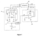
- the system includes a motor and driver 10, an amplifier 20 and a microprocessor 30.
- the motor and driver 10 includes a driving circuit 12, a sensing inductor 14, and control logic 16.
- the sensing inductor 14 is connected in series with and senses a signal from the motor M. The sensed signal is fed to the amplifier 20. The polarity of the signal is reversed, and the magnitude of the signal is amplified, such as to 5 volts, in order for the microprocessor 30 to better read the output pulses from the amplifier 20.
- the control software in the microprocessor is configured to enable the microprocessor to eliminate false readings.
- the microprocessor includes a pulse reading input/output (I/O) port 32 which receives the incoming pulses from the amplifier 20.
- the pulse reading I/O port 32 is programmed so as to be sensitive to only the rising edges of the pulses.
- An interrupt service routine is triggered by the rising edge of each pulse and the pulse is counted.
- the I/O port 32 is then masked for most of the remainder of the pulse period to filter out noise. For a good filtering result, the masking time of the I/O port needs to be determined dynamically.
- the sensing inductor by nature also helps to filter electrical noises, enhancing the reliability of the system without the need for expensive filters.
- a command input to the microprocessor, Vcom which is generally an analog input, triggers the control process which is summarized in Figure 2.
- a calibration process 42 is initiated to determine the full range of travel of the motor (or actuator) and the current position of an associated structure being controlled, such as a door on a plenum of an HVAC system.
- the number of pulses necessary to complete the full range of travel between positional limits is determined.
- the number of motor shaft revolutions is directly related to the number of pulses.
- a DC motor having three coils and two poles which represents the preferred embodiment, should have six pulses per revolution.
- the number of revolutions of the motor shaft necessary to complete the full range of motion from one positional limit to the other is 50, assuming the number of pulses for the full range of travel is 300.
- the system is ready to accept commands.
- the microprocessor Upon receipt of the analog input, Vcom, triggering the control process, the microprocessor reads 44 and converts the analog command to a digital signal. The converted input is then associated with the position of the motor shaft in pulses. For example, assuming the input is 50% of the maximum input which represents the overall travel of the actuator, and the number of pulses for the full travel is 300, then the number of pulses representing the current input command is 150. The pulse count result is then read 46 and compared 48 with the digital command signal to determine the mode of the actuator. If there is a difference 50 between the pulse count and the digital command signal, driving of the actuator 52 is initiated. In the absence of a difference 50, the control process ends 54. The conversion and comparison may be accomplished in software or may be implemented using a separate analog-to-digital converter and comparator, or similar structures, as would be known by persons of skill in the art.
- the actuator working modes include FORWARD, REVERSE, BRAKING and STOP.
- FORWARD mode the actuator is driven in a clockwise direction; in REVERSE mode, the actuator is driven in a counter-clockwise direction.
- the processor 30, in response to a difference between the pulse count and the digital command signal, issues an appropriate command to the motor and driver 10 through data lines D1 and D2, in response to which the actuator (or motor M) is driven until the desired position is achieved.
- the driving circuit 12 applies voltage to the motor M, drives the motor (actuator) in the appropriate direction to reduce the position difference to zero (five revolutions), and then cuts off the voltage to the motor and awaits a next command.
- the control logic 16 controls which transistors are on or off, in response to the commands from the microprocessor. While software may be used, the control logic 16 is preferably embodied in hardware. The control logic may be set up to respond to the command signals received from D1 and D2 in a number of ways. For example, if D1 is logical "1" and D2 is logical "0", then FORWARD operation is indicated and source driver T1 and sink driver T2 are turned on. Conversely, if D1 is "0" while D2 is a logical "1”, then REVERSE mode is indicated and source driver T3 and sink driver T4 are turned on.
- both D1 and D2 are "0”, then BRAKING is indicated and source drivers T1 and T3 are turned off while sink drivers T2 and T4 are turned on. Finally, if both D1 and D2 are logical "1”, then STOP mode is indicated and no transistors are turned on. When so configured, other combinations would, of course, be effective.
- the microprocessor may be connected directly to the four transistors, T1, T2, T3 and T4, through four lines, with each transistor thereby responding directly to a respective command from the microprocessor.
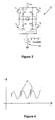
- the motor M and driving circuit 12 is depicted in Figure 3.
- the dotted line represents the current flow when source driver T1 and sink driver T2 are turned on.
- FORWARD operation the current flows along a path starting with the motor power supply, Vm, to source driver T1, to motor, to sink driver T2, and then to sensing inductor 14.
- REVERSE operation the direction of the current will change when source driver T3 and sink driver T4 are turned on and, at the same time, source driver T1 and sink driver T2 are turned off. In REVERSE operation, then, the current flows along a path from motor power supply, Vm, to source driver T3, to sink driver T4, and then to sensing inductor 14.
- the two source drivers, T1 and T3 are turned off and the two sink drivers, T2 and T4, are turned on.
- the current will go either through a path from the motor M, to sink driver T4, to inductor 14, to diode D2 and back to motor M, or will follow a path from the motor M, to sink driver T2, to inductor 14, to diode D4, and back to motor M.
- the current waveform of the permanent magnet DC motor is graphically depicted in Figure 4.
- V L(di/dt).
- the differentiation operation amplifies the sharp falling edges 15 of the pulses in the motor current, representatively six pulses per revolution.
- the value of the sensing inductor needs to be optimized to obtain maximum system efficiency. If the value of the inductor is too small, the inductor will not be sensitive enough to current signals. On the other hand, if the value is too great, the resistance will also be too great, resulting in reduced system efficiency. In addition, it is not cost effective to use a large sensing inductor. In the preferred embodiment shown, an inductor having an inductance value of 0.47mH is used.
- the system may be embodied to include a motor and driver 10, a sensing inductor 14, an amplifier 60, a pulse regulator 70 and a processor 80.
- the voltage drop across the inductive sensor 14 is input to the amplifier 60.
- Output pulses from the amplifier 60 go through the pulse regulator 70 to trigger generation of a width-controlled square wave.
- the pulse regulator 70 can hold the signal until the processor is ready to proceed.
- the square wave pulses are then sent to the processor 80 for shaft position and speed control through the motor and driver 10.
- a pulse width control filter technique is used to filter out signal noises in the vicinity of each pulse. These noises arise, among other possible contributors, from brush bounce at the end of each commutator event.
Landscapes
- Engineering & Computer Science (AREA)
- Power Engineering (AREA)
- Control Of Direct Current Motors (AREA)
- Control Of Multiple Motors (AREA)
Abstract
Description
Claims (14)
- A position control system for an actuator comprising:a driving circuit coupled to a motor;a sensing inductor connected in series with said motor through said driving circuit for sensing a signal from said motor;an amplifier for receiving and amplifying the sensed signal; anda microprocessor for receiving and counting incoming pulses from said amplifier to obtain a pulse count, said microprocessor comparing the pulse count with a command input and, responsive to a difference between said pulse count and said command input, issuing a command signal to said driving circuit to initiate driving of said actuator.
- The system as set forth in claim 1, wherein said microprocessor is configured with input/output port and an interrupt service routine which is triggered by rising edges of said incoming pulses.
- The system as set forth in claim 2, wherein, after a pulse count, said input/output port is masked for a remainder of an associated pulse period.
- The system as set forth in claim 1, wherein the sensed signal is a voltage drop across said sensing inductor.
- The system as set forth in claim 1, wherein said sensing inductor has an inductance value of approximately 0.47mH.
- A position control system for an actuator comprising:a driving circuit coupled to a motor;a sensing inductor connected in series with said motor through said driving circuit for sensing a voltage drop from said motor; anda processing unit for receiving incoming pulses and, responsive to a difference between a pulse count and a command input, issuing a command signal to said driving circuit to initiate driving of said actuator.
- The system as set forth in claim 6, further comprising:an amplifier coupled between said sensing inductor and said processing unit.
- The system as set forth in claim 7, further comprising:a pulse regulator coupled between said amplifier and said processing unit for generating a width-controlled square wave for input to said processing unit.
- The system as set forth in claim 6, said processing unit configured to count incoming pulses, compare a pulse count with a command input and, responsive to a difference between said pulse count and said command input, said processing unit issuing a command signal to said driving circuit to initiate driving of said actuator.
- The system as set forth in claim 6, wherein said sensing inductor has an inductance value of approximately 0.47mH.
- A method for sensing actuator position using an inductive sensor, comprising the steps of:monitoring changes in current signals from a motor through voltage drops across the inductive sensor;receiving, by an amplifier, a sensed signal from the inductive sensor, said amplifier reversing a polarity of and amplifying said signal;reading, by a microprocessor, incoming pulses from said amplifier;determining a pulse count;receiving, by said microprocessor, an actuator position command input;comparing said pulse count with said received actuator position command input; anddriving said actuator in response to a difference between said pulse count and said command input.
- The method as set forth in claim 11, further comprising before the step of comparing, the steps of:calibrating the microprocessor by determining a full range of motor travel in pulses; andassociating an input voltage with a motor shaft position in pulses.
- The system as set forth in claim 11, wherein the step of determining a pulse count is triggered by rising edges of said incoming pulses at an input/output port.
- The system as set forth in claim 13, wherein, after a pulse count, said input/output port is masked for a remainder of an associated pulse period.
Applications Claiming Priority (2)
| Application Number | Priority Date | Filing Date | Title |
|---|---|---|---|
| US923438 | 2001-08-08 | ||
| US09/923,438 US6437533B1 (en) | 2001-08-08 | 2001-08-08 | Actuator position control with inductive sensing |
Publications (3)
| Publication Number | Publication Date |
|---|---|
| EP1286236A2 true EP1286236A2 (en) | 2003-02-26 |
| EP1286236A3 EP1286236A3 (en) | 2006-06-07 |
| EP1286236B1 EP1286236B1 (en) | 2012-02-22 |
Family
ID=25448688
Family Applications (1)
| Application Number | Title | Priority Date | Filing Date |
|---|---|---|---|
| EP02010808A Expired - Lifetime EP1286236B1 (en) | 2001-08-08 | 2002-05-15 | Actuator position control with inductive sensing |
Country Status (3)
| Country | Link |
|---|---|
| US (2) | US6437533B1 (en) |
| EP (1) | EP1286236B1 (en) |
| AT (1) | ATE546767T1 (en) |
Cited By (1)
| Publication number | Priority date | Publication date | Assignee | Title |
|---|---|---|---|---|
| WO2004084383A1 (en) * | 2003-03-20 | 2004-09-30 | Siemens Vdo Automotive Inc. | Detection method and structure with rfi choke for brush dc motor |
Families Citing this family (27)
| Publication number | Priority date | Publication date | Assignee | Title |
|---|---|---|---|---|
| WO2001095471A1 (en) * | 2000-06-06 | 2001-12-13 | Leopold Kostal Gmbh & Co. Kg | Method for detecting the rotational position of the drive shaft of a dc motor |
| US6507128B2 (en) | 2001-05-23 | 2003-01-14 | General Electric Company | Low-energy storage fast-start uninterruptible power supply system and method |
| US6788096B2 (en) * | 2002-04-12 | 2004-09-07 | Kelsey-Hayes Co. | Method for measuring current in a pulse count positioning system |
| US6851620B2 (en) * | 2003-04-30 | 2005-02-08 | Invensys Building Systems, Inc. | Floating actuator control system and method |
| US6900657B2 (en) | 2003-09-24 | 2005-05-31 | Saia-Burgess Automotive, Inc. | Stall detection circuit and method |
| JP4127251B2 (en) * | 2004-07-23 | 2008-07-30 | 株式会社デンソー | DC motor rotation information detector |
| US7170253B2 (en) * | 2004-07-27 | 2007-01-30 | Honeywell International Inc. | Automotive door latch control by motor current monitoring |
| US7284570B1 (en) | 2005-02-16 | 2007-10-23 | The United States Of America As Represented By The Secretary Of The Navy | Electrically powered valve for controlling, monitoring and evaluating fluid flow |
| US7064509B1 (en) * | 2005-03-14 | 2006-06-20 | Visteon Global Technologies, Inc. | Apparatus for DC motor position detection with capacitive ripple current extraction |
| US7352145B2 (en) * | 2005-10-04 | 2008-04-01 | Delphi Technologies, Inc. | Voltage-sensitive oscillator frequency for rotor position detection scheme |
| US7474068B2 (en) * | 2005-10-04 | 2009-01-06 | Delphi Technologies, Inc. | Position detection and external driver multiplexing system for DC motors |
| US7180257B1 (en) * | 2005-10-04 | 2007-02-20 | Delphi Technologies, Inc. | Method of brake pulse rejection in commutation pulse detection circuits |
| US7589487B2 (en) * | 2005-10-04 | 2009-09-15 | Delphi Technologies, Inc. | Method of selectable simultaneous/sequential motor drive in a multiple drive circuit including failure detection |
| US7190129B1 (en) | 2005-12-14 | 2007-03-13 | Visteon Global Technologies, Inc. | System and method for drift compensation when using pulse count controlled motors |
| US7342369B2 (en) * | 2006-02-17 | 2008-03-11 | Lear Corporation | Differential ripple detection method and system |
| US7710081B2 (en) | 2006-10-27 | 2010-05-04 | Direct Drive Systems, Inc. | Electromechanical energy conversion systems |
| EP1936797A2 (en) | 2006-12-22 | 2008-06-25 | VDO Automotive AG | Device for adjusting an actuator |
| WO2008095750A1 (en) * | 2007-02-09 | 2008-08-14 | Continental Automotive Gmbh | Apparatus for adjusting an actuator with simplified drive |
| US20080298784A1 (en) * | 2007-06-04 | 2008-12-04 | Mark Allen Kastner | Method of Sensing Speed of Electric Motors and Generators |
| GB0803737D0 (en) * | 2008-02-29 | 2008-04-09 | Melexis Nv | Pulse count control for brushed DC motor driven by pulse width modulation |
| US8193746B2 (en) * | 2008-05-23 | 2012-06-05 | Lear Corporation | Automotive electric motor speed control system |
| US8040007B2 (en) | 2008-07-28 | 2011-10-18 | Direct Drive Systems, Inc. | Rotor for electric machine having a sleeve with segmented layers |
| US8742715B2 (en) | 2011-06-09 | 2014-06-03 | Simmonds Precision Products, Inc. | System and method for providing control of an electric motor using inductive rotary sensor |
| CN104430133A (en) * | 2014-11-13 | 2015-03-25 | 无锡悟莘科技有限公司 | Fuzzy control system for aquaculture oxygen enrichment |
| NL2019723B1 (en) * | 2017-10-13 | 2019-04-23 | Mci Mirror Controls Int Netherlands B V | Method and device for providing information on an annular displacement of a DC electromotor |
| FR3079177B1 (en) * | 2018-03-22 | 2020-11-06 | Aml Systems | DIRECT CURRENT ELECTRIC MOTOR LIGHTING CORRECTION DEVICE FOR MOTOR VEHICLES. |
| US20240128901A1 (en) * | 2022-10-13 | 2024-04-18 | Texas Instruments Incorporated | Single chip advanced adaptive sensorless motor shaft position detection |
Family Cites Families (25)
| Publication number | Priority date | Publication date | Assignee | Title |
|---|---|---|---|---|
| US3346725A (en) | 1964-07-10 | 1967-10-10 | Gen Motors Corp | Commutator pulse counting apparatus |
| JPS5542596B2 (en) * | 1972-08-14 | 1980-10-31 | ||
| US3969658A (en) * | 1975-01-17 | 1976-07-13 | Emerson Electric Co. | Motor and control system having cyclic reversal and unidirectional capabilities |
| US4510426A (en) * | 1982-07-30 | 1985-04-09 | Lectron Products, Inc. | Memory power seat controller |
| DE3527906A1 (en) * | 1985-08-03 | 1987-02-12 | Keiper Recaro Gmbh Co | Circuit arrangement for positioning an object which can be adjusted by means of an adjusting device |
| JPS62189945A (en) | 1986-02-12 | 1987-08-19 | Konishiroku Photo Ind Co Ltd | Motor |
| US4864483A (en) * | 1986-09-25 | 1989-09-05 | Wisconsin Alumni Research Foundation | Static power conversion method and apparatus having essentially zero switching losses and clamped voltage levels |
| US4967134A (en) * | 1989-02-27 | 1990-10-30 | Losic Novica A | Synthesis of load-independent ac drive systems |
| US4924158A (en) * | 1989-04-03 | 1990-05-08 | General Motors Corporation | Motor driver protection circuit |
| DE4024160A1 (en) * | 1989-08-11 | 1991-02-14 | Siemens Ag | DC level controller with antiphase clocked switch pairs - performs two-term control of inductive load current maintained at desired value by selective switching circuit |
| USH939H (en) | 1989-10-02 | 1991-07-02 | The United States Of America As Represented By The Secretary Of The Navy | Commutator pulse tachometer |
| US5132602A (en) * | 1990-10-02 | 1992-07-21 | Calsonic International, Inc. | Actuator positioning apparatus |
| US5343382A (en) * | 1993-04-05 | 1994-08-30 | Delco Electronics Corp. | Adaptive current control |
| KR100371965B1 (en) * | 1994-03-31 | 2003-03-31 | 다이킨 고교 가부시키가이샤 | Brushless DC Motor Drive Control Method and Apparatus and Electric Equipment |
| CN1063887C (en) * | 1994-07-25 | 2001-03-28 | 大金工业株式会社 | High-efficiency motor device and motor control method |
| US5729067A (en) * | 1995-08-30 | 1998-03-17 | Eaton Corporation | Method and apparatus for closed loop position control in a linear motor system |
| US5838515A (en) * | 1996-04-30 | 1998-11-17 | Quantum Corporation | PWM/linear driver for disk drive voice coil actuator |
| US5821701A (en) * | 1996-05-21 | 1998-10-13 | Teggatz; Ross | Boost regulator circuit with stoarge capacitor for reduced power consumption |
| US5898288A (en) * | 1997-01-29 | 1999-04-27 | Hewlett-Packard Company | Inexpensive motion control using DC motors |
| US5869939A (en) | 1997-01-31 | 1999-02-09 | Hewlett-Packard Company | Direct current motor with imbalanced winding for closed-loop feedback control |
| US5798624A (en) * | 1997-02-28 | 1998-08-25 | Lucas Industries | Motor circuit |
| US5982571A (en) * | 1997-06-30 | 1999-11-09 | Quantum Corporation | Disk drive with closed loop commutator and actuator oscillator |
| DE19729238C1 (en) | 1997-07-09 | 1998-08-27 | Telefunken Microelectron | Speed determining method for mechanically commutated DC motors |
| US6208132B1 (en) | 1998-11-02 | 2001-03-27 | General Electric Company | Non-intrusive speed sensing for induction motors |
| US6078154A (en) * | 1999-02-12 | 2000-06-20 | Delco Electronics Corporation | Circuitry for determining actuator position |
-
2001
- 2001-08-08 US US09/923,438 patent/US6437533B1/en not_active Expired - Lifetime
-
2002
- 2002-05-15 EP EP02010808A patent/EP1286236B1/en not_active Expired - Lifetime
- 2002-05-15 AT AT02010808T patent/ATE546767T1/en active
- 2002-08-19 US US10/222,971 patent/US6847179B2/en not_active Expired - Lifetime
Cited By (2)
| Publication number | Priority date | Publication date | Assignee | Title |
|---|---|---|---|---|
| WO2004084383A1 (en) * | 2003-03-20 | 2004-09-30 | Siemens Vdo Automotive Inc. | Detection method and structure with rfi choke for brush dc motor |
| US6960895B2 (en) | 2003-03-20 | 2005-11-01 | Siemens Vdo Automotive Inc. | Coupled RFI choke as stall detection means for brush type DC motor |
Also Published As
| Publication number | Publication date |
|---|---|
| US20030052637A1 (en) | 2003-03-20 |
| EP1286236B1 (en) | 2012-02-22 |
| ATE546767T1 (en) | 2012-03-15 |
| US6437533B1 (en) | 2002-08-20 |
| EP1286236A3 (en) | 2006-06-07 |
| US6847179B2 (en) | 2005-01-25 |
Similar Documents
| Publication | Publication Date | Title |
|---|---|---|
| US6437533B1 (en) | Actuator position control with inductive sensing | |
| US7122982B2 (en) | DC motor rotation information detecting device | |
| US4228396A (en) | Electronic tachometer and combined brushless motor commutation and tachometer system | |
| US5483135A (en) | Adaptive system and method for controlling vehicle window operation | |
| US7768219B2 (en) | Microcontroller interface with hall element | |
| CN111566936B (en) | Ripple counting circuit including varying ripple threshold detection | |
| US5554913A (en) | Blower system for vehicle air-conditioners | |
| US6104185A (en) | Method and device for operating a position sensor | |
| US6222362B1 (en) | Method for detecting the position and direction of motion of a moving part mounted on an electric motor | |
| GB2169107A (en) | Control system for an automatic door | |
| KR101031962B1 (en) | Position control device of motorized memory seat for automobile | |
| WO1992006420A1 (en) | Actuator positioning apparatus | |
| CN112713821A (en) | Method and system for closed-loop control of brush motor | |
| Afjei et al. | Sensorless speed/position control of brushed DC motor | |
| CN101743523A (en) | A watchdog circuit that provides a temperature-dependent signal to the ELV's microcontroller | |
| US7166980B1 (en) | Methods and apparatus for monitoring a brushed permanent magnet motor using back-emf measurements | |
| CN115250084A (en) | Parasitic Pulse Elimination Circuit | |
| KR101869841B1 (en) | Wiper drive | |
| CN212278147U (en) | Motor drive device and car | |
| US6788096B2 (en) | Method for measuring current in a pulse count positioning system | |
| US7112959B2 (en) | Comparator circuit and rotation detector | |
| JP2519433Y2 (en) | Piston position detector for fluid pressure equipment | |
| CN115425881A (en) | Regulating device, motor-driven valve and method for operating a regulating device | |
| JP3042581B2 (en) | Rotation detection device | |
| JPH0571719U (en) | Incremental signal detector |
Legal Events
| Date | Code | Title | Description |
|---|---|---|---|
| PUAI | Public reference made under article 153(3) epc to a published international application that has entered the european phase |
Free format text: ORIGINAL CODE: 0009012 |
|
| AK | Designated contracting states |
Kind code of ref document: A2 Designated state(s): AT BE CH CY DE DK ES FI FR GB GR IE IT LI LU MC NL PT SE TR |
|
| AX | Request for extension of the european patent |
Extension state: AL LT LV MK RO SI |
|
| RAP1 | Party data changed (applicant data changed or rights of an application transferred) |
Owner name: SAIA-BURGESS AUTOMOTIVE INC. |
|
| PUAL | Search report despatched |
Free format text: ORIGINAL CODE: 0009013 |
|
| AK | Designated contracting states |
Kind code of ref document: A3 Designated state(s): AT BE CH CY DE DK ES FI FR GB GR IE IT LI LU MC NL PT SE TR |
|
| AX | Request for extension of the european patent |
Extension state: AL LT LV MK RO SI |
|
| 17P | Request for examination filed |
Effective date: 20060727 |
|
| AKX | Designation fees paid |
Designated state(s): AT BE CH CY DE DK ES FI FR GB GR IE IT LI LU MC NL PT SE TR |
|
| 17Q | First examination report despatched |
Effective date: 20070824 |
|
| GRAP | Despatch of communication of intention to grant a patent |
Free format text: ORIGINAL CODE: EPIDOSNIGR1 |
|
| RIC1 | Information provided on ipc code assigned before grant |
Ipc: H02P 7/29 20060101AFI20110905BHEP |
|
| RIC1 | Information provided on ipc code assigned before grant |
Ipc: G05B 19/19 20060101AFI20110922BHEP |
|
| GRAS | Grant fee paid |
Free format text: ORIGINAL CODE: EPIDOSNIGR3 |
|
| GRAA | (expected) grant |
Free format text: ORIGINAL CODE: 0009210 |
|
| AK | Designated contracting states |
Kind code of ref document: B1 Designated state(s): AT BE CH CY DE DK ES FI FR GB GR IE IT LI LU MC NL PT SE TR |
|
| REG | Reference to a national code |
Ref country code: GB Ref legal event code: FG4D |
|
| REG | Reference to a national code |
Ref country code: CH Ref legal event code: EP |
|
| REG | Reference to a national code |
Ref country code: AT Ref legal event code: REF Ref document number: 546767 Country of ref document: AT Kind code of ref document: T Effective date: 20120315 |
|
| REG | Reference to a national code |
Ref country code: IE Ref legal event code: FG4D |
|
| REG | Reference to a national code |
Ref country code: DE Ref legal event code: R096 Ref document number: 60242236 Country of ref document: DE Effective date: 20120412 |
|
| REG | Reference to a national code |
Ref country code: CH Ref legal event code: NV Representative=s name: FIAMMENGHI-FIAMMENGHI |
|
| REG | Reference to a national code |
Ref country code: NL Ref legal event code: VDEP Effective date: 20120222 |
|
| PG25 | Lapsed in a contracting state [announced via postgrant information from national office to epo] |
Ref country code: NL Free format text: LAPSE BECAUSE OF FAILURE TO SUBMIT A TRANSLATION OF THE DESCRIPTION OR TO PAY THE FEE WITHIN THE PRESCRIBED TIME-LIMIT Effective date: 20120222 |
|
| PG25 | Lapsed in a contracting state [announced via postgrant information from national office to epo] |
Ref country code: GR Free format text: LAPSE BECAUSE OF FAILURE TO SUBMIT A TRANSLATION OF THE DESCRIPTION OR TO PAY THE FEE WITHIN THE PRESCRIBED TIME-LIMIT Effective date: 20120523 Ref country code: FI Free format text: LAPSE BECAUSE OF FAILURE TO SUBMIT A TRANSLATION OF THE DESCRIPTION OR TO PAY THE FEE WITHIN THE PRESCRIBED TIME-LIMIT Effective date: 20120222 Ref country code: PT Free format text: LAPSE BECAUSE OF FAILURE TO SUBMIT A TRANSLATION OF THE DESCRIPTION OR TO PAY THE FEE WITHIN THE PRESCRIBED TIME-LIMIT Effective date: 20120622 Ref country code: BE Free format text: LAPSE BECAUSE OF FAILURE TO SUBMIT A TRANSLATION OF THE DESCRIPTION OR TO PAY THE FEE WITHIN THE PRESCRIBED TIME-LIMIT Effective date: 20120222 |
|
| REG | Reference to a national code |
Ref country code: AT Ref legal event code: MK05 Ref document number: 546767 Country of ref document: AT Kind code of ref document: T Effective date: 20120222 |
|
| PG25 | Lapsed in a contracting state [announced via postgrant information from national office to epo] |
Ref country code: CY Free format text: LAPSE BECAUSE OF FAILURE TO SUBMIT A TRANSLATION OF THE DESCRIPTION OR TO PAY THE FEE WITHIN THE PRESCRIBED TIME-LIMIT Effective date: 20120222 |
|
| PG25 | Lapsed in a contracting state [announced via postgrant information from national office to epo] |
Ref country code: SE Free format text: LAPSE BECAUSE OF FAILURE TO SUBMIT A TRANSLATION OF THE DESCRIPTION OR TO PAY THE FEE WITHIN THE PRESCRIBED TIME-LIMIT Effective date: 20120222 Ref country code: DK Free format text: LAPSE BECAUSE OF FAILURE TO SUBMIT A TRANSLATION OF THE DESCRIPTION OR TO PAY THE FEE WITHIN THE PRESCRIBED TIME-LIMIT Effective date: 20120222 |
|
| PLBE | No opposition filed within time limit |
Free format text: ORIGINAL CODE: 0009261 |
|
| STAA | Information on the status of an ep patent application or granted ep patent |
Free format text: STATUS: NO OPPOSITION FILED WITHIN TIME LIMIT |
|
| PG25 | Lapsed in a contracting state [announced via postgrant information from national office to epo] |
Ref country code: MC Free format text: LAPSE BECAUSE OF NON-PAYMENT OF DUE FEES Effective date: 20120531 |
|
| 26N | No opposition filed |
Effective date: 20121123 |
|
| GBPC | Gb: european patent ceased through non-payment of renewal fee |
Effective date: 20120522 |
|
| PG25 | Lapsed in a contracting state [announced via postgrant information from national office to epo] |
Ref country code: AT Free format text: LAPSE BECAUSE OF FAILURE TO SUBMIT A TRANSLATION OF THE DESCRIPTION OR TO PAY THE FEE WITHIN THE PRESCRIBED TIME-LIMIT Effective date: 20120222 |
|
| REG | Reference to a national code |
Ref country code: IE Ref legal event code: MM4A |
|
| REG | Reference to a national code |
Ref country code: DE Ref legal event code: R097 Ref document number: 60242236 Country of ref document: DE Effective date: 20121123 |
|
| PG25 | Lapsed in a contracting state [announced via postgrant information from national office to epo] |
Ref country code: ES Free format text: LAPSE BECAUSE OF FAILURE TO SUBMIT A TRANSLATION OF THE DESCRIPTION OR TO PAY THE FEE WITHIN THE PRESCRIBED TIME-LIMIT Effective date: 20120602 Ref country code: GB Free format text: LAPSE BECAUSE OF NON-PAYMENT OF DUE FEES Effective date: 20120522 Ref country code: IE Free format text: LAPSE BECAUSE OF NON-PAYMENT OF DUE FEES Effective date: 20120515 |
|
| PG25 | Lapsed in a contracting state [announced via postgrant information from national office to epo] |
Ref country code: TR Free format text: LAPSE BECAUSE OF FAILURE TO SUBMIT A TRANSLATION OF THE DESCRIPTION OR TO PAY THE FEE WITHIN THE PRESCRIBED TIME-LIMIT Effective date: 20120222 |
|
| PG25 | Lapsed in a contracting state [announced via postgrant information from national office to epo] |
Ref country code: LU Free format text: LAPSE BECAUSE OF NON-PAYMENT OF DUE FEES Effective date: 20120515 |
|
| REG | Reference to a national code |
Ref country code: FR Ref legal event code: PLFP Year of fee payment: 15 |
|
| REG | Reference to a national code |
Ref country code: FR Ref legal event code: PLFP Year of fee payment: 16 |
|
| REG | Reference to a national code |
Ref country code: FR Ref legal event code: PLFP Year of fee payment: 17 |
|
| PGFP | Annual fee paid to national office [announced via postgrant information from national office to epo] |
Ref country code: CH Payment date: 20200515 Year of fee payment: 19 Ref country code: DE Payment date: 20200513 Year of fee payment: 19 |
|
| PGFP | Annual fee paid to national office [announced via postgrant information from national office to epo] |
Ref country code: IT Payment date: 20210412 Year of fee payment: 20 Ref country code: FR Payment date: 20210412 Year of fee payment: 20 |
|
| REG | Reference to a national code |
Ref country code: DE Ref legal event code: R119 Ref document number: 60242236 Country of ref document: DE |
|
| REG | Reference to a national code |
Ref country code: CH Ref legal event code: PL |
|
| PG25 | Lapsed in a contracting state [announced via postgrant information from national office to epo] |
Ref country code: CH Free format text: LAPSE BECAUSE OF NON-PAYMENT OF DUE FEES Effective date: 20210531 Ref country code: LI Free format text: LAPSE BECAUSE OF NON-PAYMENT OF DUE FEES Effective date: 20210531 |
|
| PG25 | Lapsed in a contracting state [announced via postgrant information from national office to epo] |
Ref country code: DE Free format text: LAPSE BECAUSE OF NON-PAYMENT OF DUE FEES Effective date: 20211201 |