EP1286232A1 - Image forming apparatus - Google Patents
Image forming apparatus Download PDFInfo
- Publication number
- EP1286232A1 EP1286232A1 EP02018140A EP02018140A EP1286232A1 EP 1286232 A1 EP1286232 A1 EP 1286232A1 EP 02018140 A EP02018140 A EP 02018140A EP 02018140 A EP02018140 A EP 02018140A EP 1286232 A1 EP1286232 A1 EP 1286232A1
- Authority
- EP
- European Patent Office
- Prior art keywords
- power supply
- power
- control means
- error
- application
- Prior art date
- Legal status (The legal status is an assumption and is not a legal conclusion. Google has not performed a legal analysis and makes no representation as to the accuracy of the status listed.)
- Granted
Links
- 230000004044 response Effects 0.000 claims description 8
- 238000011084 recovery Methods 0.000 abstract description 9
- 238000012545 processing Methods 0.000 description 8
- 230000002708 enhancing effect Effects 0.000 description 4
- 230000006854 communication Effects 0.000 description 3
- 238000004891 communication Methods 0.000 description 3
- 231100001261 hazardous Toxicity 0.000 description 2
- 230000003287 optical effect Effects 0.000 description 2
- 238000013021 overheating Methods 0.000 description 2
- 238000012546 transfer Methods 0.000 description 2
- 230000007175 bidirectional communication Effects 0.000 description 1
- 230000015572 biosynthetic process Effects 0.000 description 1
- 230000010485 coping Effects 0.000 description 1
- 238000010586 diagram Methods 0.000 description 1
- 238000010438 heat treatment Methods 0.000 description 1
- 239000004973 liquid crystal related substance Substances 0.000 description 1
- 238000000034 method Methods 0.000 description 1
- 230000003442 weekly effect Effects 0.000 description 1
Images


Classifications
-
- G—PHYSICS
- G03—PHOTOGRAPHY; CINEMATOGRAPHY; ANALOGOUS TECHNIQUES USING WAVES OTHER THAN OPTICAL WAVES; ELECTROGRAPHY; HOLOGRAPHY
- G03G—ELECTROGRAPHY; ELECTROPHOTOGRAPHY; MAGNETOGRAPHY
- G03G15/00—Apparatus for electrographic processes using a charge pattern
- G03G15/50—Machine control of apparatus for electrographic processes using a charge pattern, e.g. regulating differents parts of the machine, multimode copiers, microprocessor control
- G03G15/5004—Power supply control, e.g. power-saving mode, automatic power turn-off
-
- G—PHYSICS
- G03—PHOTOGRAPHY; CINEMATOGRAPHY; ANALOGOUS TECHNIQUES USING WAVES OTHER THAN OPTICAL WAVES; ELECTROGRAPHY; HOLOGRAPHY
- G03G—ELECTROGRAPHY; ELECTROPHOTOGRAPHY; MAGNETOGRAPHY
- G03G15/00—Apparatus for electrographic processes using a charge pattern
- G03G15/20—Apparatus for electrographic processes using a charge pattern for fixing, e.g. by using heat
- G03G15/2003—Apparatus for electrographic processes using a charge pattern for fixing, e.g. by using heat using heat
-
- H—ELECTRICITY
- H04—ELECTRIC COMMUNICATION TECHNIQUE
- H04N—PICTORIAL COMMUNICATION, e.g. TELEVISION
- H04N1/00—Scanning, transmission or reproduction of documents or the like, e.g. facsimile transmission; Details thereof
- H04N1/00002—Diagnosis, testing or measuring; Detecting, analysing or monitoring not otherwise provided for
-
- H—ELECTRICITY
- H04—ELECTRIC COMMUNICATION TECHNIQUE
- H04N—PICTORIAL COMMUNICATION, e.g. TELEVISION
- H04N1/00—Scanning, transmission or reproduction of documents or the like, e.g. facsimile transmission; Details thereof
- H04N1/00002—Diagnosis, testing or measuring; Detecting, analysing or monitoring not otherwise provided for
- H04N1/00007—Diagnosis, testing or measuring; Detecting, analysing or monitoring not otherwise provided for relating to particular apparatus or devices
- H04N1/00015—Reproducing apparatus
-
- H—ELECTRICITY
- H04—ELECTRIC COMMUNICATION TECHNIQUE
- H04N—PICTORIAL COMMUNICATION, e.g. TELEVISION
- H04N1/00—Scanning, transmission or reproduction of documents or the like, e.g. facsimile transmission; Details thereof
- H04N1/00002—Diagnosis, testing or measuring; Detecting, analysing or monitoring not otherwise provided for
- H04N1/00026—Methods therefor
- H04N1/00037—Detecting, i.e. determining the occurrence of a predetermined state
-
- H—ELECTRICITY
- H04—ELECTRIC COMMUNICATION TECHNIQUE
- H04N—PICTORIAL COMMUNICATION, e.g. TELEVISION
- H04N1/00—Scanning, transmission or reproduction of documents or the like, e.g. facsimile transmission; Details thereof
- H04N1/00002—Diagnosis, testing or measuring; Detecting, analysing or monitoring not otherwise provided for
- H04N1/00026—Methods therefor
- H04N1/0005—Methods therefor in service, i.e. during normal operation
-
- H—ELECTRICITY
- H04—ELECTRIC COMMUNICATION TECHNIQUE
- H04N—PICTORIAL COMMUNICATION, e.g. TELEVISION
- H04N1/00—Scanning, transmission or reproduction of documents or the like, e.g. facsimile transmission; Details thereof
- H04N1/00002—Diagnosis, testing or measuring; Detecting, analysing or monitoring not otherwise provided for
- H04N1/00026—Methods therefor
- H04N1/00063—Methods therefor using at least a part of the apparatus itself, e.g. self-testing
-
- H—ELECTRICITY
- H04—ELECTRIC COMMUNICATION TECHNIQUE
- H04N—PICTORIAL COMMUNICATION, e.g. TELEVISION
- H04N1/00—Scanning, transmission or reproduction of documents or the like, e.g. facsimile transmission; Details thereof
- H04N1/00002—Diagnosis, testing or measuring; Detecting, analysing or monitoring not otherwise provided for
- H04N1/00071—Diagnosis, testing or measuring; Detecting, analysing or monitoring not otherwise provided for characterised by the action taken
- H04N1/00082—Adjusting or controlling
- H04N1/00084—Recovery or repair, e.g. self-repair
-
- H—ELECTRICITY
- H04—ELECTRIC COMMUNICATION TECHNIQUE
- H04N—PICTORIAL COMMUNICATION, e.g. TELEVISION
- H04N1/00—Scanning, transmission or reproduction of documents or the like, e.g. facsimile transmission; Details thereof
- H04N1/00885—Power supply means, e.g. arrangements for the control of power supply to the apparatus or components thereof
- H04N1/00888—Control thereof
- H04N1/00891—Switching on or off, e.g. for saving power when not in use
-
- H—ELECTRICITY
- H04—ELECTRIC COMMUNICATION TECHNIQUE
- H04N—PICTORIAL COMMUNICATION, e.g. TELEVISION
- H04N1/00—Scanning, transmission or reproduction of documents or the like, e.g. facsimile transmission; Details thereof
- H04N1/00885—Power supply means, e.g. arrangements for the control of power supply to the apparatus or components thereof
- H04N1/00901—Using different supplies or connection to an external supply
-
- H—ELECTRICITY
- H04—ELECTRIC COMMUNICATION TECHNIQUE
- H04N—PICTORIAL COMMUNICATION, e.g. TELEVISION
- H04N1/00—Scanning, transmission or reproduction of documents or the like, e.g. facsimile transmission; Details thereof
- H04N1/00885—Power supply means, e.g. arrangements for the control of power supply to the apparatus or components thereof
- H04N1/00904—Arrangements for supplying power to different circuits or for supplying power at different levels
-
- H—ELECTRICITY
- H04—ELECTRIC COMMUNICATION TECHNIQUE
- H04N—PICTORIAL COMMUNICATION, e.g. TELEVISION
- H04N1/00—Scanning, transmission or reproduction of documents or the like, e.g. facsimile transmission; Details thereof
- H04N1/00912—Arrangements for controlling a still picture apparatus or components thereof not otherwise provided for
- H04N1/00915—Assigning priority to, or interrupting, a particular operation
-
- H—ELECTRICITY
- H04—ELECTRIC COMMUNICATION TECHNIQUE
- H04N—PICTORIAL COMMUNICATION, e.g. TELEVISION
- H04N1/00—Scanning, transmission or reproduction of documents or the like, e.g. facsimile transmission; Details thereof
- H04N1/00885—Power supply means, e.g. arrangements for the control of power supply to the apparatus or components thereof
Definitions
- the present invention relates to an image forming apparatus and more particularly to an image forming apparatus including two power supply lines for insuring safety in the event of a hazardous error and automatically restoring original conditions after recovery from the error.
- a facsimile apparatus, copier, copier, printer or similar electrophotographic image forming apparatus includes a fixing unit that fixes a toner image formed on a sheet with heat. More specifically, a latent image is formed on a photoconductive element by a light beam modulated in accordance with image data and then developed by toner. The resulting toner image is transferred from the photoconductive element to a sheet.
- a heat roller fixes the toner image on the sheet with heat generated by a heater accommodated in the heat roller.
- the heater heating the heat roller is controlled to preselected temperature while being protected from overheating.
- a thermistor senses the temperature of the heater while sending its output to a controller.
- the controller ON/OFF controls the heater in accordance with the output of the thermistor to thereby maintain the heater at preselected temperature.
- Japanese Patent Laid-Open Publication No. 8-251317 discloses an image forming apparatus configured to reduce power consumption when a power supply is turned off.
- Japanese Patent Laid-Open Publication No. 2000-289885 for example, teaches an image forming apparatus implemented as a multifunction printer including two power supply lines. If the power supply of a multifunction printer is fully turned off, then the printer cannot receive print data from, e.g., a personal computer or prevents its weekly timer from operating.
- the two power supply lines continuously energize part of control sections with a minimum of power and causes, on the generation or a print request or similar request, such a control section to start the entire printer system. This successfully enhances efficient manual operation while saving power.
- an image forming apparatus It is a common practice with an image forming apparatus to cope with, e.g., the runaway of a CPU (Central Processing Unit) or controller by protecting a heater from overheating with a temperature fuse or a thermostat or with an analog comparator.
- this kind of scheme is not a drastic measure for protecting the image forming apparatus in the event of the runaway of the controller or similar critical error.
- the image forming apparatus is apt to start a fire when a drive motor does not stop rotating, when the heater does not turn off due to the runaway of the CPU or when a high-tension output does not stop. In such a case, even when the CPU is reset, the high-tension output is likely to again turn on.
- all modes set beforehand are deleted and must be set all over again, resulting in inefficient manual operation.
- An image forming apparatus of the present invention includes a main controller for controlling various sections included in a signal system and an engine controller for controlling various sections included in a load system.
- a first power supply applies power to the main control means while a second power supply applies power to the engine control means.
- a first establishing/interrupting device selectively establishes or interrupts the application of power to the second power supply in response to the output of the first power supply.
- the engine controller sends to the main controller status information representative of original conditions set up before the error and error information representative of the error.
- the main controller On receiving the status information and error information, the main controller stores the status information in its memory and causes the first establishing/interrupting device to interrupt the application of power to the second power supply, thereby interrupting the application of power to the load system.
- an image forming apparatus embodying the present invention is shown and generally designated by the reference numeral 1.
- the image forming apparatus 1 includes a main controller 2, an engine controller 3, a first power supply 4, a second power supply 5, a main switch 6, a power supply plug 7, a first relay 8, a second relay 9, a control panel 10, a high-tension section 11, a drive motor 12, a heater controller 13, and a heater 14 for fixation.
- the image forming apparatus 1 additionally includes a sheet feeder and an image forming engine, which includes a charger, an optical writing unit and an image transfer station, although not shown specifically.
- the charger uniformly charges the surface of a photoconductive drum not shown.
- the optical writing unit scans the charged surface of the drum with a laser beam in accordance with image data to thereby form a latent image.
- a developing unit develops the latent image with toner for thereby forming a corresponding toner image.
- the toner image is transferred from the drum to a sheet fed from the sheet feeder at the image transfer station.
- the first power supply 4 rectifies and adjusts AC 100 V input thereto via the main switch 6 while feeding the resulting DC voltage to the main controller 2 and control panel 10. At the same time, AC 100 V is routed through a drive coil 8a included in the first relay 8 to the main controller 2.
- the main controller 2 selectively turns on or turns off the first relay 8 by ON/OFF controlling a current to flow through the drive coil 8a.
- the main controller 2 includes a CPU, a ROM (Read Only Memory) and a RAM (Random Access Memory) although not shown specifically.
- the main controller 2 controls the various signal lines of the apparatus 1 in accordance with the operation of the control panel 10 on the basis of a program stored in the ROM, thereby controlling the basic operation of the apparatus 1. Further, the main controller 2 executes protection processing in the event of a critical error, which will be described later specifically. In addition, the main controller 2 controls a display included in the control panel 10.
- the control panel 10 includes various keys to be operated by the operator of the apparatus 1 in addition to the display, which may be implemented by an LCD (Liquid Crystal Display).
- the control panel 10 receives the DC voltage from the first power supply 4 and delivers the contents of operation input on the keys to the main controller 2. At the same time, the control panel 10 displays the contents of operation as well as various kinds of information to be reported by the apparatus 1 to the operator.
- the first relay 8 which plays the role of first establishing/interrupting means, is connected between the power supply plug 7 and the second power supply 5.
- the main controller 2 selectively turns on or turns off the first relay 8 to thereby establish or interrupt the feed of the AC voltage from the power supply plug 7 to the second power supply 5.
- the second power supply 5 rectifies and adjusts the AC voltage input via the first relay 8 while feeding the resulting DC voltage to the engine.controller 3 and other loads and drivelines. More specifically, the DC voltage output from the second power supply 5 is routed through a drive coil 9a included in the second relay 9 to the engine controller 3. The engine controller 3 selectively establishes or interrupts a current to flow through the drive coil 9a to thereby turn on or turn off the second relay 9.
- the engine controller 3 includes a CPU, a ROM and a RAM and controls, based on a program stored in the ROM and commands received from the main controller 2, the operation of the image forming engine, the feed and conveyance of a sheet, and the high-tension section 11 and drive motor 12 that constitute a drive system. More specifically, the main controller 2 and engine controller 3 are interconnected by a bidirectional communication line and interchange control timing commands with each other.
- the second relay 9 which plays the role of second establishing/interrupting means, is connected between the power supply plug 7 and the heater controller 13.
- the engine controller 3 selectively turns on or turns off the second relay 9 to thereby establish or interrupt the feed of the AC voltage from the power supply plug 7 to the heater controller 13.
- the heater controller 13 controls, under the control of the engine controller 3, a current to be fed to the heater 14 in order to control the temperature of a heat roller not shown.
- the heater 14 is accommodated in the heat roller that is included in a fixing unit.
- the operation of the illustrative embodiment will be described hereinafter.
- the illustrative embodiment is characterized by the previously mentioned protection processing that insures safety in the event of a critical error and then automatically restores original conditions after recovery from the error. More specifically, when the operator turns on the main switch 6, the commercial AC voltage is applied to the first power supply 4 and rectified and adjusted thereby. The resulting DC voltage is fed from the first power supply 4 to the main controller 2 and control panel 10. In response, the CPU of the main controller 2 executes initialization and then turns on the first relay 8 for thereby feeding the commercial AC voltage to the second power supply 5.
- the second power supply 5 rectifies and adjusts the commercial AC voltage and feeds the resulting DC voltage to the engine controller 3 and other loads and drivelines.
- the CPU of the engine controller 3 starts communicating with the main controller 2.
- the CPU of the engine controller 3 turns on the second relay 9 to thereby feed the commercial AC voltage to the heater controller 13.
- the heater controller 13 starts controlling the temperature of the heater 14.
- FIG. 2 demonstrates the protection processing to be executed after the procedure described above.
- the engine controller 3 references the outputs of various sensors, not shown, in order to determine whether or not a critical error has occurred (step S101).
- the critical error refers to, e.g., an occurrence that the high-tension output or the heater 14 does not turn off (OFF) or that the drive motor 12 does not stop rotating. If such an error has occurred, the engine controller 3 delivers a signal for interrupting the current being fed to the heater 14 to the heater controller 13 (step S102). In response, the heater controller 13 turns off the second relay 9 (step S103).
- the engine controller 3 executes usual error processing without turning off the second relay 9.
- the engine controller 3 After turning off the second relay 9, the engine controller 3 sends to the main controller 2 an error code representative of the critical error and status information including current modes (e.g. copying conditions) and data representative of the number of remaining copies to be output or remaining job (step S104). The engine controller 3 then executes usual processing for stopping copying operation (step S105).
- the main controller 2 On receiving the error code and status information from the engine controller 3 (step S201), the main controller 2 displays an error message on the display of the control panel 10 (step S202), stores the received data in the RAM or similar memory thereof, and then turns off the first relay 8 (step S203).
- a service person for example, is urged by the error message appearing on the control panel 10 to settle the error and then operate a switch, not shown, positioned on the control panel 10 for indicating recovery (OK).
- the main controller 2 determines whether or not the error has been settled (step S204). If the answer of the step S204 is YES, then the main controller 2 turns on the first relay 8 and sends a recovery command representative of the recovery from the error to the engine controller 3 (step S205). The main controller 2 then determines whether or not it has received a ready command from the engine controller 3 (step S206).
- step S106 On receiving the recovery command from the main controller 2, the engine controller 3 executes initialization (step S106) and then determines whether or not the error has been settled (step S107). If the answer of the step S107 is NO, then the steps S101 through S107 are repeated. If the answer of the step S107 is NO, then the engine controller 3 sends the ready command to the main controller 2 (step S108) and then waits for the status information from the main controller (step S109).
- step S206 On receiving the ready command from the engine controller 3 (YES, step S206), the main controller 2 cancels the error message appearing on the control panel 10 (step S207). Subsequently, the main controller 2 sends the status information stored in the memory in the step S201 to the engine controller 3 (step S208) and then remains in a stand-by state (step S209).
- step S109 the engine controller 3 restores the original operation modes selected before the error, waits until the operator presses a start button, not shown, positioned on the control panel 10, and then causes image formation to start (step S110).
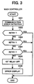
- FIG. 3 shows protection processing to be executed by the main controller 2 when an error occurs in communication between the main controller 2 and the engine controller 3.
- the main controller 2 detects a communication error (step S301)
- it repeats a retry for requesting a command up to three times in consideration of the influence of, e.g., noise (steps S302 through S304).
- the retry is successful (YES, step S302, 303 or 304)
- the main controller 2 executes the processing described with reference to FIG. 2.
- step S304 If even the last retry is unsuccessful (NO, step S304), then the main controller 2 turns off the first relay 8 by determining that the CPU of the engine controller 3 has run away (step S305). The main controller 2 then displays a communication error on the display of the control panel 10 (step S306). As a result, the application of the commercial AC voltage to the second power supply 5 is interrupted, so that the heater 14 and all the loads are turned off. This surely, safely interrupts the operation of the apparatus 1 although a sheet may be left on a conveyance path inside the apparatus 1.
- the present invention provides an image forming apparatus capable of surely turning off power supplies assigned to a charging section and a drive section when critical errors, which are apt to bring about a first or similar hazard, occur in such power supplies, thereby enhancing safety. Further, the apparatus of the present invention automatically restores original conditions after recovery from the error for thereby enhancing efficient manual operation to follow.
- An image forming apparatus of the present invention includes a main controller and an engine controller.
- the engine controller sends to the main controller status information representative of original conditions set up before the error and error information representative of the error and causes a second relay to interrupt the application of an AC voltage to a heater controller.
- the main controller stores the received status information in its memory and turns off a first relay to thereby interrupt the application of the AC voltage to a second power supply. After recovery from the error, the main controller again turns on the first relay and thereby causes the engine controller to restore the original conditions represented by the status information.
Landscapes
- Engineering & Computer Science (AREA)
- Multimedia (AREA)
- Signal Processing (AREA)
- Health & Medical Sciences (AREA)
- Biomedical Technology (AREA)
- General Health & Medical Sciences (AREA)
- Physics & Mathematics (AREA)
- General Physics & Mathematics (AREA)
- Microelectronics & Electronic Packaging (AREA)
- Control Or Security For Electrophotography (AREA)
- Facsimiles In General (AREA)
Abstract
Description
Claims (7)
- An image forming apparatus comprising:wherein when an error occurs in any one of the sections of the load system, said engine control means sends to said main control means status information representative of original conditions set up before said error and error information representative of said error, andmain control means for controlling various sections included in a signal system;engine control means for controlling various sections included in a load system;a first power supply for applying power to said main control means;a second power supply for applying power to said engine control means; andfirst establishing/interrupting means for selectively establishing or interrupting application of the power to said second power supply in response to an output of said first power supply;
on receiving the status information and the error information, said main controller stores said status information in a memory thereof and causes said first establishing/interrupting means to interrupt the application of the power to said second power supply, thereby interrupting the application of the power to the load system. - The apparatus as claimed in claim1, further comprising second establishing/interrupting means for selectively establishing or interrupting the application of the power to the load system in response to an output of said second power supply.
- The apparatus as claimed in claim 2, wherein when said first establishing/interrupting means applies the power to said second power supply after interruption of application of the power to said load system, said main control means sends the status information stored to said engine control means, causing said engine control means to control said load system in accordance with said status information.
- The apparatus as claimed in claim 3, wherein the sections of the load system comprise at least fixing means, high-tension means, and a drive motor.
- The apparatus as claimed in claim 4, wherein only when an error occurs in any one of the fixing means, the high-tension means and the drive motor, said engine control means sends the error information representative of said error to said main controller, causing said main control means to interrupt the application of the power to said second power supply via said first establishing/interrupting means.
- The apparatus as claimed in claim 5, wherein on detecting an error in interchange of information between said main control means and said engine control means, said main controller causes said first establishing/interrupting means to interrupt the application of the power to said second power supply.
- A device for controlling application of power, comprising:wherein when an error occurs in the load circuitry, said second control means detects said error and sends error information to said second first control means, andfirst control means for controlling application of power to signal circuitry;second control means for controlling application of power to load circuitry;a first power supply for applying power to said first control means;a second power supply for applying power to said second control means; andestablishing/interrupting means connected between an AC power supply and an input of said second power supply for selectively establishing or interrupting the application of power to said second power supply;
in response to the error information, said first control means turns off said establishing/interrupting means to thereby interrupt the application of power to said second power supply and said load circuitry connected to said second power supply.
Applications Claiming Priority (2)
| Application Number | Priority Date | Filing Date | Title |
|---|---|---|---|
| JP2001247902A JP4382310B2 (en) | 2001-08-17 | 2001-08-17 | Image forming apparatus and control method thereof |
| JP2001247902 | 2001-08-17 |
Publications (2)
| Publication Number | Publication Date |
|---|---|
| EP1286232A1 true EP1286232A1 (en) | 2003-02-26 |
| EP1286232B1 EP1286232B1 (en) | 2008-01-02 |
Family
ID=19077143
Family Applications (1)
| Application Number | Title | Priority Date | Filing Date |
|---|---|---|---|
| EP02018140A Expired - Lifetime EP1286232B1 (en) | 2001-08-17 | 2002-08-14 | Image forming apparatus |
Country Status (4)
| Country | Link |
|---|---|
| US (1) | US6711361B2 (en) |
| EP (1) | EP1286232B1 (en) |
| JP (1) | JP4382310B2 (en) |
| DE (1) | DE60224341T2 (en) |
Families Citing this family (2)
| Publication number | Priority date | Publication date | Assignee | Title |
|---|---|---|---|---|
| JP2003063101A (en) * | 2001-08-27 | 2003-03-05 | Matsushita Graphic Communication Systems Inc | Composite machine, terminal for connection therewith and network system comprising them |
| JP7455592B2 (en) | 2020-01-20 | 2024-03-26 | キヤノン株式会社 | Image forming device |
Citations (5)
| Publication number | Priority date | Publication date | Assignee | Title |
|---|---|---|---|---|
| US4538902A (en) * | 1979-05-17 | 1985-09-03 | Canon Kabushiki Kaisha | Image formation apparatus |
| US4639864A (en) * | 1976-09-07 | 1987-01-27 | Tandem Computers Incorporated | Power interlock system and method for use with multiprocessor systems |
| US4740671A (en) * | 1983-06-07 | 1988-04-26 | Canon Kabushiki Kaisha | Temperature control apparatus for detecting an abnormality in a heater in a copying machine or the like |
| US4994852A (en) * | 1987-08-18 | 1991-02-19 | Minolta Camera Kabushiki Kaisha | Image forming apparatus having a malfunction detection device and power shutdown therefor |
| US5325209A (en) * | 1991-04-18 | 1994-06-28 | Ricoh Company, Ltd. | Multiplex image forming apparatus |
Family Cites Families (8)
| Publication number | Priority date | Publication date | Assignee | Title |
|---|---|---|---|---|
| JPS6184661A (en) * | 1984-10-02 | 1986-04-30 | Mita Ind Co Ltd | Device for preventing paper jam in copying machine |
| US4785328A (en) | 1985-12-27 | 1988-11-15 | Ricoh Company, Ltd. | Electrophotographic copying machine |
| US4782369A (en) | 1986-11-04 | 1988-11-01 | Ricoh Company, Ltd. | Device for illuminating an original document |
| US5131079A (en) | 1988-03-28 | 1992-07-14 | Ricoh Company, Ltd. | Method of controlling a display and a display control device for a copying machine |
| JP2536713Y2 (en) | 1989-11-29 | 1997-05-28 | 株式会社リコー | Electrophotographic equipment |
| JP3167349B2 (en) | 1991-06-12 | 2001-05-21 | 株式会社リコー | Image forming device |
| JP3183733B2 (en) | 1992-11-26 | 2001-07-09 | 株式会社リコー | Waste toner detection device for image forming apparatus |
| JPH08152822A (en) * | 1994-11-30 | 1996-06-11 | Mita Ind Co Ltd | Image forming device |
-
2001
- 2001-08-17 JP JP2001247902A patent/JP4382310B2/en not_active Expired - Fee Related
-
2002
- 2002-08-14 DE DE60224341T patent/DE60224341T2/en not_active Expired - Lifetime
- 2002-08-14 EP EP02018140A patent/EP1286232B1/en not_active Expired - Lifetime
- 2002-08-16 US US10/219,746 patent/US6711361B2/en not_active Expired - Lifetime
Patent Citations (5)
| Publication number | Priority date | Publication date | Assignee | Title |
|---|---|---|---|---|
| US4639864A (en) * | 1976-09-07 | 1987-01-27 | Tandem Computers Incorporated | Power interlock system and method for use with multiprocessor systems |
| US4538902A (en) * | 1979-05-17 | 1985-09-03 | Canon Kabushiki Kaisha | Image formation apparatus |
| US4740671A (en) * | 1983-06-07 | 1988-04-26 | Canon Kabushiki Kaisha | Temperature control apparatus for detecting an abnormality in a heater in a copying machine or the like |
| US4994852A (en) * | 1987-08-18 | 1991-02-19 | Minolta Camera Kabushiki Kaisha | Image forming apparatus having a malfunction detection device and power shutdown therefor |
| US5325209A (en) * | 1991-04-18 | 1994-06-28 | Ricoh Company, Ltd. | Multiplex image forming apparatus |
Also Published As
| Publication number | Publication date |
|---|---|
| EP1286232B1 (en) | 2008-01-02 |
| DE60224341T2 (en) | 2008-12-18 |
| JP2003058002A (en) | 2003-02-28 |
| DE60224341D1 (en) | 2008-02-14 |
| JP4382310B2 (en) | 2009-12-09 |
| US20030035655A1 (en) | 2003-02-20 |
| US6711361B2 (en) | 2004-03-23 |
Similar Documents
| Publication | Publication Date | Title |
|---|---|---|
| US7251429B2 (en) | Image forming apparatus with an energy storage that can be discharged, and with a display of residual energy in the storage | |
| US7206527B2 (en) | Information forming apparatus equipped with a fixing unit | |
| US5710959A (en) | Image forming apparatus having a function of turning on a power supply using a timer | |
| JP4721249B2 (en) | Power supply device and image forming apparatus | |
| US6711361B2 (en) | Power management system in an image forming apparatus | |
| US6202162B1 (en) | Data processing system having separable data-processing devices and a deactivable power-saving function | |
| JP4815384B2 (en) | Image forming system | |
| JP2002247752A (en) | Power supply device, heater power supply device, fixing device, and image forming device | |
| JPH10268713A (en) | Automatic power-off circuit | |
| JPH0532747B2 (en) | ||
| JP4685524B2 (en) | Image forming apparatus | |
| JP2007226061A (en) | Image forming apparatus | |
| JP4956169B2 (en) | Image forming apparatus | |
| JP4666611B2 (en) | Charging system and power storage server | |
| JP2002325434A (en) | Power failure information management method, power supply device, and image forming apparatus | |
| JP4760217B2 (en) | Image forming apparatus | |
| JPH10143006A (en) | Fixing device | |
| JP6702273B2 (en) | Image processing device | |
| JPH0869327A (en) | Heater control device and recording device including the device | |
| KR20070088122A (en) | Fixing system of image forming apparatus and fixing fixing method thereof | |
| JPH08248814A (en) | Fixing unit control method and apparatus | |
| JP2024005846A (en) | Image forming apparatus, warning method and management system for image forming apparatus | |
| JP3152457B2 (en) | Copier | |
| JP2023145968A (en) | Image forming apparatus | |
| JPH04223480A (en) | Controller for image forming device |
Legal Events
| Date | Code | Title | Description |
|---|---|---|---|
| PUAI | Public reference made under article 153(3) epc to a published international application that has entered the european phase |
Free format text: ORIGINAL CODE: 0009012 |
|
| 17P | Request for examination filed |
Effective date: 20020814 |
|
| AK | Designated contracting states |
Kind code of ref document: A1 Designated state(s): AT BE BG CH CY CZ DE DK EE ES FI FR GB GR IE IT LI LU MC NL PT SE SK TR |
|
| AX | Request for extension of the european patent |
Extension state: AL LT LV MK RO SI |
|
| 17Q | First examination report despatched |
Effective date: 20030618 |
|
| AKX | Designation fees paid |
Designated state(s): DE FR GB |
|
| GRAP | Despatch of communication of intention to grant a patent |
Free format text: ORIGINAL CODE: EPIDOSNIGR1 |
|
| GRAS | Grant fee paid |
Free format text: ORIGINAL CODE: EPIDOSNIGR3 |
|
| GRAA | (expected) grant |
Free format text: ORIGINAL CODE: 0009210 |
|
| AK | Designated contracting states |
Kind code of ref document: B1 Designated state(s): DE FR GB |
|
| REG | Reference to a national code |
Ref country code: GB Ref legal event code: FG4D |
|
| REF | Corresponds to: |
Ref document number: 60224341 Country of ref document: DE Date of ref document: 20080214 Kind code of ref document: P |
|
| ET | Fr: translation filed | ||
| PLBE | No opposition filed within time limit |
Free format text: ORIGINAL CODE: 0009261 |
|
| STAA | Information on the status of an ep patent application or granted ep patent |
Free format text: STATUS: NO OPPOSITION FILED WITHIN TIME LIMIT |
|
| 26N | No opposition filed |
Effective date: 20081003 |
|
| REG | Reference to a national code |
Ref country code: FR Ref legal event code: PLFP Year of fee payment: 15 |
|
| REG | Reference to a national code |
Ref country code: FR Ref legal event code: PLFP Year of fee payment: 16 |
|
| PGFP | Annual fee paid to national office [announced via postgrant information from national office to epo] |
Ref country code: FR Payment date: 20170822 Year of fee payment: 16 Ref country code: DE Payment date: 20170822 Year of fee payment: 16 Ref country code: GB Payment date: 20170822 Year of fee payment: 16 |
|
| REG | Reference to a national code |
Ref country code: DE Ref legal event code: R119 Ref document number: 60224341 Country of ref document: DE |
|
| GBPC | Gb: european patent ceased through non-payment of renewal fee |
Effective date: 20180814 |
|
| PG25 | Lapsed in a contracting state [announced via postgrant information from national office to epo] |
Ref country code: DE Free format text: LAPSE BECAUSE OF NON-PAYMENT OF DUE FEES Effective date: 20190301 |
|
| PG25 | Lapsed in a contracting state [announced via postgrant information from national office to epo] |
Ref country code: FR Free format text: LAPSE BECAUSE OF NON-PAYMENT OF DUE FEES Effective date: 20180831 |
|
| PG25 | Lapsed in a contracting state [announced via postgrant information from national office to epo] |
Ref country code: GB Free format text: LAPSE BECAUSE OF NON-PAYMENT OF DUE FEES Effective date: 20180814 |