EP1285843B1 - Fastener for vehicle - Google Patents
Fastener for vehicle Download PDFInfo
- Publication number
- EP1285843B1 EP1285843B1 EP01127521A EP01127521A EP1285843B1 EP 1285843 B1 EP1285843 B1 EP 1285843B1 EP 01127521 A EP01127521 A EP 01127521A EP 01127521 A EP01127521 A EP 01127521A EP 1285843 B1 EP1285843 B1 EP 1285843B1
- Authority
- EP
- European Patent Office
- Prior art keywords
- fastener
- main body
- legs
- keeper
- fixing base
- Prior art date
- Legal status (The legal status is an assumption and is not a legal conclusion. Google has not performed a legal analysis and makes no representation as to the accuracy of the status listed.)
- Expired - Lifetime
Links
- 238000003780 insertion Methods 0.000 claims description 34
- 230000037431 insertion Effects 0.000 claims description 34
- 210000003739 neck Anatomy 0.000 description 12
- 230000008878 coupling Effects 0.000 description 8
- 238000010168 coupling process Methods 0.000 description 8
- 238000005859 coupling reaction Methods 0.000 description 8
- 238000005299 abrasion Methods 0.000 description 5
- 230000002093 peripheral effect Effects 0.000 description 5
- 230000000994 depressogenic effect Effects 0.000 description 2
- 238000012986 modification Methods 0.000 description 2
- 230000004048 modification Effects 0.000 description 2
- 230000006835 compression Effects 0.000 description 1
- 238000007906 compression Methods 0.000 description 1
- 230000000593 degrading effect Effects 0.000 description 1
- 238000000034 method Methods 0.000 description 1
- 229920003002 synthetic resin Polymers 0.000 description 1
- 239000000057 synthetic resin Substances 0.000 description 1
Images


Classifications
-
- F—MECHANICAL ENGINEERING; LIGHTING; HEATING; WEAPONS; BLASTING
- F16—ENGINEERING ELEMENTS AND UNITS; GENERAL MEASURES FOR PRODUCING AND MAINTAINING EFFECTIVE FUNCTIONING OF MACHINES OR INSTALLATIONS; THERMAL INSULATION IN GENERAL
- F16B—DEVICES FOR FASTENING OR SECURING CONSTRUCTIONAL ELEMENTS OR MACHINE PARTS TOGETHER, e.g. NAILS, BOLTS, CIRCLIPS, CLAMPS, CLIPS OR WEDGES; JOINTS OR JOINTING
- F16B21/00—Means for preventing relative axial movement of a pin, spigot, shaft or the like and a member surrounding it; Stud-and-socket releasable fastenings
- F16B21/02—Releasable fastening devices locking by rotation
-
- F—MECHANICAL ENGINEERING; LIGHTING; HEATING; WEAPONS; BLASTING
- F16—ENGINEERING ELEMENTS AND UNITS; GENERAL MEASURES FOR PRODUCING AND MAINTAINING EFFECTIVE FUNCTIONING OF MACHINES OR INSTALLATIONS; THERMAL INSULATION IN GENERAL
- F16B—DEVICES FOR FASTENING OR SECURING CONSTRUCTIONAL ELEMENTS OR MACHINE PARTS TOGETHER, e.g. NAILS, BOLTS, CIRCLIPS, CLAMPS, CLIPS OR WEDGES; JOINTS OR JOINTING
- F16B2/00—Friction-grip releasable fastenings
-
- B—PERFORMING OPERATIONS; TRANSPORTING
- B62—LAND VEHICLES FOR TRAVELLING OTHERWISE THAN ON RAILS
- B62D—MOTOR VEHICLES; TRAILERS
- B62D29/00—Superstructures, understructures, or sub-units thereof, characterised by the material thereof
- B62D29/04—Superstructures, understructures, or sub-units thereof, characterised by the material thereof predominantly of synthetic material
- B62D29/048—Connections therefor, e.g. joints
-
- B—PERFORMING OPERATIONS; TRANSPORTING
- B60—VEHICLES IN GENERAL
- B60R—VEHICLES, VEHICLE FITTINGS, OR VEHICLE PARTS, NOT OTHERWISE PROVIDED FOR
- B60R19/00—Wheel guards; Radiator guards, e.g. grilles; Obstruction removers; Fittings damping bouncing force in collisions
- B60R19/02—Bumpers, i.e. impact receiving or absorbing members for protecting vehicles or fending off blows from other vehicles or objects
- B60R19/24—Arrangements for mounting bumpers on vehicles
-
- B—PERFORMING OPERATIONS; TRANSPORTING
- B60—VEHICLES IN GENERAL
- B60R—VEHICLES, VEHICLE FITTINGS, OR VEHICLE PARTS, NOT OTHERWISE PROVIDED FOR
- B60R19/00—Wheel guards; Radiator guards, e.g. grilles; Obstruction removers; Fittings damping bouncing force in collisions
- B60R19/02—Bumpers, i.e. impact receiving or absorbing members for protecting vehicles or fending off blows from other vehicles or objects
- B60R19/18—Bumpers, i.e. impact receiving or absorbing members for protecting vehicles or fending off blows from other vehicles or objects characterised by the cross-section; Means within the bumper to absorb impact
- B60R2019/1886—Bumper fascias and fastening means therefor
-
- F—MECHANICAL ENGINEERING; LIGHTING; HEATING; WEAPONS; BLASTING
- F16—ENGINEERING ELEMENTS AND UNITS; GENERAL MEASURES FOR PRODUCING AND MAINTAINING EFFECTIVE FUNCTIONING OF MACHINES OR INSTALLATIONS; THERMAL INSULATION IN GENERAL
- F16B—DEVICES FOR FASTENING OR SECURING CONSTRUCTIONAL ELEMENTS OR MACHINE PARTS TOGETHER, e.g. NAILS, BOLTS, CIRCLIPS, CLAMPS, CLIPS OR WEDGES; JOINTS OR JOINTING
- F16B13/00—Dowels or other devices fastened in walls or the like by inserting them in holes made therein for that purpose
- F16B13/12—Separate metal or non-separate or non-metal dowel sleeves fastened by inserting the screw, nail or the like
- F16B13/124—Separate metal or non-separate or non-metal dowel sleeves fastened by inserting the screw, nail or the like fastened by inserting a threaded element, e.g. screw or bolt
-
- F—MECHANICAL ENGINEERING; LIGHTING; HEATING; WEAPONS; BLASTING
- F16—ENGINEERING ELEMENTS AND UNITS; GENERAL MEASURES FOR PRODUCING AND MAINTAINING EFFECTIVE FUNCTIONING OF MACHINES OR INSTALLATIONS; THERMAL INSULATION IN GENERAL
- F16B—DEVICES FOR FASTENING OR SECURING CONSTRUCTIONAL ELEMENTS OR MACHINE PARTS TOGETHER, e.g. NAILS, BOLTS, CIRCLIPS, CLAMPS, CLIPS OR WEDGES; JOINTS OR JOINTING
- F16B5/00—Joining sheets or plates, e.g. panels, to one another or to strips or bars parallel to them
- F16B5/02—Joining sheets or plates, e.g. panels, to one another or to strips or bars parallel to them by means of fastening members using screw-thread
Definitions
- the present invention relates to a structure of a vehicle fastener for fixing various parts (hereinafter, referred to "object") to a vehicle body as described by the preamble of claim 1 and disclosed in document US,A,5,211,519.
- various objects are assembled into a vehicle body by using coupling elements such as bolts, nuts, screws, fasteners and the like, wherein a fastener formed of synthetic resin has been widely used for assembling interior elements in a short time, which do not require a large coupling force, to the vehicle body without using any additional tools.
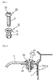
- Fig. 1 is an exploded perspective view showing a structure of a prior art fastener
- Fig. 2 is a cross-sectional view showing a fastener, which fixes a bumper cover to a vehicle body bracket.
- the structure as shown in Fig. 1 and Fig. 2 will be described in more detail below.
- the prior art fastener includes a body part 10 formed with a screw hole 11 in the center and holding jaws 12 on an outer peripheral surface of an elastic piece, and a bolt element 20 formed with a male screw part 21 to be coupled in the screw hole that is formed in the main body and a driver insertion groove 22 on a top surface.
- an insertion hole 1a formed in the fixing base 1 is conformed with an insertion hole 2a of the object 2 and the main body 10 is inserted into both of the insertion holes 1a and 2a, so that a plurality of the holding jaws 12, which are divisionally formed in the main body, becomes pursed inwardly to be inserted and returned to the initial state to be supported by the fixing base 1, as the main body 10 is completely inserted.
- the bolt element 20 has to be separated from the main body 10.
- a driver (not shown) has to be inserted into the driver insertion groove 22 formed on a top surface of the bolt element 20 and rotated in a direction to release the bolt element 20.
- a length of a neck portion formed in the main body is limited even though a thickness of the fixing base, that is, the vehicle body is determined. Therefore, in order to use parts compatibly, it is necessary to provide a main body, which has necks of different length according to the thickness of the parts to fix.
- the holding jaw portions are worn out due to fine slippage repeatedly generated in connection parts by the vibration which is repeatedly generated when driving a vehicle under the state that the object is fixed to the fixing base, thereby degrading the fixing state of the object and generating the noise.
- the male screw part formed on the outer peripheral surface becomes worn out in the process of bolt element insertion, since the bolt element is forcibly inserted into the screw hole of the main body. Therefore, the bolt element idles in the screw hole of the main body and is not released from the screw hole in spite of the rotation for releasing the object form the fixing base, and
- the present invention is directed to a fastener for a vehicle that substantially obviates one or more of the problems due to limitations and disadvantages of the related art and is defined by the features of independent claim 1.
- An object of the present invention is to provide an improved fastener for a vehicle, which may fix an object to a vehicle body regardless of the thickness of the object.
- Another object of the present invention is to provide a fastener for a vehicle that may absorb the vibration, which is generated in coupling parts of an object while the vehicle is driving, thereby preventing the abrasion of coupling parts of the fastener even though the vibration is generated.
- a further object of the present invention is to provide a fastener of which locking element may be easily separated from a main body without using any additional tools.
- a fastener for a vehicle to be inserted into an insertion hole which is formed in a fixing base of a vehicle body and an insertion hole of an object for integrating the object into the vehicle body includes a main body having a grommet to be secured on a top surface of a fixing base, an insertion hole formed in the center of the grommet, a plurality of legs formed at a lower part of the grommet, supporting surfaces formed outside the legs to be held by a lower part of the fixing base, and holding jaws formed inside the legs, a locking element having a keeper to be inserted into the insertion hole formed in the main body and held by the holding jaws of the legs by rotating by a predetermined angle, a neck formed long at an upper end part of the keeper, a flange part formed at a front end of the neck, and a rotation element formed on the flange part for rotating the keeper, a washer to
- Fig. 4 is a perspective view showing a fastener for a vehicle, which is disassembled
- Fig. 5a and Fig. 5b are cross-sectional views showing the fastener for a vehicle, which is assembled. Referring to Fig. 4 and Fig. 5a and Fig.
- the fastener for a vehicle includes a main body 30 to be fixed and supported in a fixing base 1 of a vehicle body, a locking element 40 to be fitted into the main body via an insertion hole 2a of an object 2 for fixing the object 2 to the fixing base, a washer 50 to be fitted on the locking element to be connected to a top surface of the object 2, and an elastic element 60 such as a coil spring for closely contacting the washer fitted on the locking element to the top surface of the object and simultaneously maintaining the holding state between the main body 30 and the locking element 40.
- the main body 30 to be fitted and supported in the insertion hole 1a of the fixing base 1 of the vehicle body includes a grommet 31 to be secured on a top surface of the fixing base 1, an insertion hole 32 formed in the center of the grommet 31 to be inserted by the locking element 40, a plurality of legs 33 formed at a lower part of the grommet, supporting surfaces 34 formed outside the legs to be held by a lower part of the fixing base, and holding jaws 35 formed inside the legs, as shown in Fig. 4.
- leg elements 33 downwardly formed to the grommet 31 of the main body 30 are in parallel to one another and the holding jaws 35 formed on the inner surfaces of the legs are protruded by a uniform width.
- the insertion hole 1a of the fixing base 1 of the vehicle body should be formed in the shape of square.
- legs 33 in the shape of cylinder, which is divided into a plurality of sections, instead of the parallel shape.
- a stopper 3 is formed for supporting a surface of the grommet 31 for preventing the main body 30 from idling with respect to the fixing base 1 of the vehicle body when the locking element 40 locked in the main body 30 rotates.
- the supporting surfaces formed on the legs of the main body 30 are to be slant surfaces which become wider downwardly and then narrower again, so that the legs 33 of the main body 30 may be easily inserted into the insertion hole 1a of the fixing base and the main body 30 may be used without changing the specification of the main body 30 even though a thickness of the fixing base 1 of the vehicle body is changed.
- the locking element 40 for supporting the object 2 coupled with the main body 30 with respect to the fixing base 1 includes a keeper 41 to be inserted into the insertion hole formed in the main body and rotated by a predetermined angle so as to be held by the holding jaws 35 of the legs 33, a neck 42 formed long at an upper part of the keeper, a flange part 43 formed at a front end of the neck, and a rotation element 44 formed on the flange part for rotating the keeper.
- the keeper 41 formed in the locking element 40 is in the shape of "-" to be fitted between the holding jaws 35 formed inside the legs 33 and then held by the holding jaws 35 when the locking element rotates.
- the shape of the keeper 41 may be formed variously according to the shapes of the legs 33 and the holding jaws 35 formed inside the legs.
- the legs 33 are formed in the shape of cylinder which is divided into three or four sections and the holding jaws 35 are formed on inner peripheral surfaces of the legs according to the shape of the legs, then the keeper 41 is formed in the shape of triangular or square protruded piece for passing spaces between the holding jaws formed on the inner peripheral surfaces of the legs, so that the keeper 41 is fitted in the insertion hole 32 of the main body to pass a space between the holding jaws 35.
- the locking element 40 is rotated by a predetermined angle, the keeper 41 is held by the holding jaws 35.
- rotation element 44 formed on the flange part 43 of the locking element 40 is a handle in the shape of knob in Fig. 4 and Fig. 5, the rotation element may also be a driver insertion groove formed in the flange part 43 as shown in Fig. 6.
- the elastic element 60 mounted between the flange part 43 and the washer 50 serves to absorb fine vibration, which is generated by the driving of the vehicle while the object 2 is mounted on the fixing base 1, thereby preventing the abrasion of the fastener due to the vibration.
- the main body 30 becomes lowered maintaining the contact between the supporting surfaces 34 and the bottom surface of the insertion hole 1a formed in the fixing base 1 due to the own elasticity of the legs 33 by simply pressing the main body 30 downwardly.
- the insertion hole 32 of the main body 30 is conformed with the insertion hole 2a of the object 2 and the keeper 41 of the locking element 40 is pushed into the insertion hole 32 of the main body 30 after the main body 30 is assembled into the fixing base 1 of the vehicle body as above, wherein the keeper 41 is pushed into the insertion hole after controlling its position not to be interfered by the holding jaws 35 formed inside the legs 33.
- the knob 44 serving as the rotation element is rotated to gradually rotate the locking element 40 for passing the keeper 41 through the holding jaws 35, so that the keeper 41 is held by the holding jaws 35, as shown in Fig. 5a.
- the assembling of the fastener is finished by removing the external force from the locking element 40 which is pressed and rotated by 90° as the keeper 41 passes through the holding jaws 35.
- the keeper 41 which is passed through the holding jaws 35 by the external force pressing the locking element 40, is lifted by the restoring force of the elastic element 60, so that the keeper is locked by the holding jaws 35 formed inside the legs 33 as shown in Fig. 5b, thereby locking the object 2 into the fixing base 1.
- the washer 50 fitted on the neck 42 of the locking element 40 is maintained in a close contact state with the top surface of the object 2 by the elasticity of the elastic element 60, so that the object 2 cannot move away from the fixing base 1.
- the elastic element 60 mounted between the flange part 43 and the washer 50 absorbs any fine vibration, which is generated by the driving of the vehicle while the object 2 is secured with the fixing base 1, thereby preventing the generation of the abrasion of the fastener.
- the rotation element 44 of the locking element 40 serving as the handle is pressed by hands to press the elastic element 60 down and rotated to release the locking state of the keeper 41 from the holding jaws 35. In this state, if the locking element 40 is pulled upwardly, then the object 2 is separated from the fixing base 1.
- the fastener for a vehicle according to the present invention as above has advantages as described hereinafter.
- a fastener of a single specification may fix objects having different thickness into a fixing base of a vehicle body since various thickness of the object may be received in the range of a length of the neck by the compression force of the elastic element, which is fitted on the neck of the locking element.
- the washer contacting the top surface of the object may absorb the vibration generated by the repeated driving of the vehicle while the object is fixed into the fixing base of the vehicle body by compressing the elastic element, so that the fastener may be prevented from being worn out and the generation of the noise due to the abrasion of the fastener may be prevented in advance.
- the locking element is locked into the main body by the rotation of the locking element after inserting the keeper of the locking element into the insertion hole of the main body, so that the locking element may be separated from the main body without using any additional tools and accordingly the coupling portion may be prevented from being damaged, thereby using the fastener for a long time.
- the locking element has a long neck and the rotation element is positioned in the vicinity of an opening part of the depressed groove so that the fastener may be mounted or detached easily even though the seating surface to secure the fastener is deep.
- An improved structure of a fastener for a vehicle to be used for fixing various parts to a vehicle body which includes a main body(30) to be fixed and supported in a fixing base(1) of a vehicle body, a locking element(40) to be fitted into the main body via an insertion hole(2a) of an object(2) for fixing the object(2) to the fixing base, a washer(50) to be fitted into the locking element to be connected to a top surface of the object(2), and an elastic element(60) such as a coil spring for closely contacting the washer fitted into the locking element to the top surface of the object and simultaneously maintaining the holding state between the main body(30) and the locking element(40), wherein an object may be fixed to a fixing base of the vehicle body regardless of a thickness of the object and the vibration, which is generated in a coupling portion of the object when the vehicle is driving, may be absorbed for preventing the abrasion of the coupling portion of the fastener.
Description
- The present invention relates to a structure of a vehicle fastener for fixing various parts (hereinafter, referred to "object") to a vehicle body as described by the preamble of
claim 1 and disclosed in document US,A,5,211,519. - In general, various objects are assembled into a vehicle body by using coupling elements such as bolts, nuts, screws, fasteners and the like, wherein a fastener formed of synthetic resin has been widely used for assembling interior elements in a short time, which do not require a large coupling force, to the vehicle body without using any additional tools.
- Fig. 1 is an exploded perspective view showing a structure of a prior art fastener, and Fig. 2 is a cross-sectional view showing a fastener, which fixes a bumper cover to a vehicle body bracket. The structure as shown in Fig. 1 and Fig. 2 will be described in more detail below.
- The prior art fastener includes a body part 10 formed with a
screw hole 11 in the center and holdingjaws 12 on an outer peripheral surface of an elastic piece, and abolt element 20 formed with amale screw part 21 to be coupled in the screw hole that is formed in the main body and adriver insertion groove 22 on a top surface. - As shown in Fig. 2, in order to fix the bumper cover as an
object 2 to the vehicle body as afixing base 1, aninsertion hole 1a formed in thefixing base 1 is conformed with aninsertion hole 2a of theobject 2 and the main body 10 is inserted into both of theinsertion holes holding jaws 12, which are divisionally formed in the main body, becomes pursed inwardly to be inserted and returned to the initial state to be supported by thefixing base 1, as the main body 10 is completely inserted. - In this state, if the
bolt element 20 is forcibly inserted into thescrew hole 11 formed in the main body 10, themale screw part 21 formed on the outer peripheral surface of thebolt element 20 passes through thescrew hole 11, during which the elastic piece formed with theholding jaws 12 is extended outwardly and returned to an initial state as the bolt element is completely inserted, thereby finishing the assembling of the fastener. - As described above, in order to separate the object fixed to the fixing base from the fixing base for the exchange, the
bolt element 20 has to be separated from the main body 10. - Therefore, in order to separate the
bolt element 20 from the main body 10, a driver (not shown) has to be inserted into thedriver insertion groove 22 formed on a top surface of thebolt element 20 and rotated in a direction to release thebolt element 20. - The prior art fastener has, however, disadvantages described below.
- First, a length of a neck portion formed in the main body is limited even though a thickness of the fixing base, that is, the vehicle body is determined. Therefore, in order to use parts compatibly, it is necessary to provide a main body, which has necks of different length according to the thickness of the parts to fix.
- Second, the holding jaw portions are worn out due to fine slippage repeatedly generated in connection parts by the vibration which is repeatedly generated when driving a vehicle under the state that the object is fixed to the fixing base, thereby degrading the fixing state of the object and generating the noise.
- Third, the male screw part formed on the outer peripheral surface becomes worn out in the process of bolt element insertion, since the bolt element is forcibly inserted into the screw hole of the main body. Therefore, the bolt element idles in the screw hole of the main body and is not released from the screw hole in spite of the rotation for releasing the object form the fixing base, and
- Fourth, it is difficult to fix or separate a fastener to or from a depressed groove since the groove for fixing the fastener to the object is formed deep, when the seating surface to use the fastener is deep, as shown in Fig. 3.
- Accordingly, the present invention is directed to a fastener for a vehicle that substantially obviates one or more of the problems due to limitations and disadvantages of the related art and is defined by the features of
independent claim 1. - An object of the present invention is to provide an improved fastener for a vehicle, which may fix an object to a vehicle body regardless of the thickness of the object.
- Another object of the present invention is to provide a fastener for a vehicle that may absorb the vibration, which is generated in coupling parts of an object while the vehicle is driving, thereby preventing the abrasion of coupling parts of the fastener even though the vibration is generated.
- A further object of the present invention is to provide a fastener of which locking element may be easily separated from a main body without using any additional tools.
- To achieve these and other advantages and in accordance with the purpose of the present invention, as embodied and broadly described, a fastener for a vehicle to be inserted into an insertion hole which is formed in a fixing base of a vehicle body and an insertion hole of an object for integrating the object into the vehicle body, includes a main body having a grommet to be secured on a top surface of a fixing base, an insertion hole formed in the center of the grommet, a plurality of legs formed at a lower part of the grommet, supporting surfaces formed outside the legs to be held by a lower part of the fixing base, and holding jaws formed inside the legs, a locking element having a keeper to be inserted into the insertion hole formed in the main body and held by the holding jaws of the legs by rotating by a predetermined angle, a neck formed long at an upper end part of the keeper, a flange part formed at a front end of the neck, and a rotation element formed on the flange part for rotating the keeper, a washer to be fitted on the neck of the locking element to be connected to a top surface of the object, and an elastic element fitted on the neck to be positioned between the flange df the locking means and the washer for holding the keeper of the locking element by the holding jaws of the main body.
- The accompanying drawings, which are included to provide a further understanding of the invention and are incorporated in and constitute a part of this specification, illustrate embodiments of the invention and together with the description serve to explain the principles of the invention.
- In the drawings:
- Fig. 1 is a perspective view showing a structure of a prior art fastener for a vehicle, which is disassembled;
- Fig. 2 is a cross-section view showing the prior art fastener, which fixes a bumper cover to a bracket of a vehicle body;
- Fig. 3 is a view showing the prior art fastener, which fixes an object to a fixing base having a deep seating surface;
- Fig. 4 is a perspective view showing a fastener for a vehicle according to the present invention, which is disassembled;
- Fig. 5a and Fig. 5b are cross-sectional views of the fastener for a vehicle according to the present invention, which is assembled, wherein;
- Fig. 5a is a view showing a state that a holding element is inserted into fixing holes formed in an object and a fixing base and a locking element is inserted into the holding element, and
- Fig. 5b is a view showing a state that the object is fixed to the fixing base by rotating the locking element by 90°; and
- Fig. 6 is a perspective view showing a locking element according to another embodiment of the present invention.
-
- Reference will now be made in detail to a preferred embodiment of the present invention, examples of which are illustrated in Fig. 4 to Fig. 6.
- Fig. 4 is a perspective view showing a fastener for a vehicle, which is disassembled, and Fig. 5a and Fig. 5b are cross-sectional views showing the fastener for a vehicle, which is assembled. Referring to Fig. 4 and Fig. 5a and Fig. 5b, the fastener for a vehicle according to the present invention includes a
main body 30 to be fixed and supported in afixing base 1 of a vehicle body, alocking element 40 to be fitted into the main body via aninsertion hole 2a of anobject 2 for fixing theobject 2 to the fixing base, awasher 50 to be fitted on the locking element to be connected to a top surface of theobject 2, and anelastic element 60 such as a coil spring for closely contacting the washer fitted on the locking element to the top surface of the object and simultaneously maintaining the holding state between themain body 30 and thelocking element 40. - The
main body 30 to be fitted and supported in theinsertion hole 1a of thefixing base 1 of the vehicle body includes agrommet 31 to be secured on a top surface of thefixing base 1, aninsertion hole 32 formed in the center of thegrommet 31 to be inserted by thelocking element 40, a plurality oflegs 33 formed at a lower part of the grommet, supportingsurfaces 34 formed outside the legs to be held by a lower part of the fixing base, and holdingjaws 35 formed inside the legs, as shown in Fig. 4. - The
leg elements 33 downwardly formed to thegrommet 31 of themain body 30 are in parallel to one another and theholding jaws 35 formed on the inner surfaces of the legs are protruded by a uniform width. - In the above case that the
legs 33 are formed in parallel, theinsertion hole 1a of thefixing base 1 of the vehicle body should be formed in the shape of square. - It is also possible to form the
legs 33 in the shape of cylinder, which is divided into a plurality of sections, instead of the parallel shape. - In this case, it is preferable for the sake of convenience of the disassembling or coupling work that a stopper 3 is formed for supporting a surface of the
grommet 31 for preventing themain body 30 from idling with respect to thefixing base 1 of the vehicle body when thelocking element 40 locked in themain body 30 rotates. - The supporting surfaces formed on the legs of the
main body 30 are to be slant surfaces which become wider downwardly and then narrower again, so that thelegs 33 of themain body 30 may be easily inserted into theinsertion hole 1a of the fixing base and themain body 30 may be used without changing the specification of themain body 30 even though a thickness of thefixing base 1 of the vehicle body is changed. - The
locking element 40 for supporting theobject 2 coupled with themain body 30 with respect to thefixing base 1 includes akeeper 41 to be inserted into the insertion hole formed in the main body and rotated by a predetermined angle so as to be held by theholding jaws 35 of thelegs 33, aneck 42 formed long at an upper part of the keeper, aflange part 43 formed at a front end of the neck, and arotation element 44 formed on the flange part for rotating the keeper. - The
keeper 41 formed in thelocking element 40 is in the shape of "-" to be fitted between theholding jaws 35 formed inside thelegs 33 and then held by theholding jaws 35 when the locking element rotates. - The shape of the
keeper 41 may be formed variously according to the shapes of thelegs 33 and theholding jaws 35 formed inside the legs. - For example, if the
legs 33 are formed in the shape of cylinder which is divided into three or four sections and theholding jaws 35 are formed on inner peripheral surfaces of the legs according to the shape of the legs, then thekeeper 41 is formed in the shape of triangular or square protruded piece for passing spaces between the holding jaws formed on the inner peripheral surfaces of the legs, so that thekeeper 41 is fitted in theinsertion hole 32 of the main body to pass a space between theholding jaws 35. In this state, if thelocking element 40 is rotated by a predetermined angle, thekeeper 41 is held by theholding jaws 35. - Even though the
rotation element 44 formed on theflange part 43 of thelocking element 40 is a handle in the shape of knob in Fig. 4 and Fig. 5, the rotation element may also be a driver insertion groove formed in theflange part 43 as shown in Fig. 6. - The
elastic element 60 mounted between theflange part 43 and thewasher 50 serves to absorb fine vibration, which is generated by the driving of the vehicle while theobject 2 is mounted on thefixing base 1, thereby preventing the abrasion of the fastener due to the vibration. - Now, the operation of the fastener for a vehicle structured as above according to the present invention will be described hereinafter.
- First, if the
legs 33 of the main body are pushed into theinsertion hole 1a of thefixing base 1 of the vehicle body after drawing thelegs 33 inwardly, and the external force is removed, then the inwardly drawnlegs 33 are restored to an initial state, so that the supportingsurfaces 34 of the legs contact a bottom surface of theinsertion hole 1a of thefixing base 1 and thegrommet 31 closely contact the top surface of thefixing base 1. - In case that the
grommet 31 is separated from the top surface of thefixing base 1 due to the incomplete insertion of thelegs 33 of themain body 30 with respect to theinsertion hole 1a, themain body 30 becomes lowered maintaining the contact between the supportingsurfaces 34 and the bottom surface of theinsertion hole 1a formed in thefixing base 1 due to the own elasticity of thelegs 33 by simply pressing themain body 30 downwardly. - The
insertion hole 32 of themain body 30 is conformed with theinsertion hole 2a of theobject 2 and thekeeper 41 of thelocking element 40 is pushed into theinsertion hole 32 of themain body 30 after themain body 30 is assembled into thefixing base 1 of the vehicle body as above, wherein thekeeper 41 is pushed into the insertion hole after controlling its position not to be interfered by theholding jaws 35 formed inside thelegs 33. - If the interference is not generated even though the
elastic element 60 is compressed to lower thekeeper 41 after pushing thekeeper 41 of the locking element into theinsertion hole 32 of themain body 30, theknob 44 serving as the rotation element is rotated to gradually rotate thelocking element 40 for passing thekeeper 41 through theholding jaws 35, so that thekeeper 41 is held by theholding jaws 35, as shown in Fig. 5a. - The assembling of the fastener is finished by removing the external force from the locking
element 40 which is pressed and rotated by 90° as thekeeper 41 passes through the holdingjaws 35. - Therefore, the
keeper 41, which is passed through the holdingjaws 35 by the external force pressing the lockingelement 40, is lifted by the restoring force of theelastic element 60, so that the keeper is locked by the holdingjaws 35 formed inside thelegs 33 as shown in Fig. 5b, thereby locking theobject 2 into the fixingbase 1. - The
washer 50 fitted on theneck 42 of the lockingelement 40 is maintained in a close contact state with the top surface of theobject 2 by the elasticity of theelastic element 60, so that theobject 2 cannot move away from the fixingbase 1. - Further, the
elastic element 60 mounted between theflange part 43 and thewasher 50 absorbs any fine vibration, which is generated by the driving of the vehicle while theobject 2 is secured with the fixingbase 1, thereby preventing the generation of the abrasion of the fastener. - In the meantime, if the
object 2 has to be detached from the fixingbase 1 to be exchanged with a new one due to the repeated use of the vehicle, therotation element 44 of the lockingelement 40 serving as the handle is pressed by hands to press theelastic element 60 down and rotated to release the locking state of thekeeper 41 from the holdingjaws 35. In this state, if the lockingelement 40 is pulled upwardly, then theobject 2 is separated from the fixingbase 1. - The fastener for a vehicle according to the present invention as above has advantages as described hereinafter.
- First, a fastener of a single specification may fix objects having different thickness into a fixing base of a vehicle body since various thickness of the object may be received in the range of a length of the neck by the compression force of the elastic element, which is fitted on the neck of the locking element.
- Second, the washer contacting the top surface of the object may absorb the vibration generated by the repeated driving of the vehicle while the object is fixed into the fixing base of the vehicle body by compressing the elastic element, so that the fastener may be prevented from being worn out and the generation of the noise due to the abrasion of the fastener may be prevented in advance.
- Third, the locking element is locked into the main body by the rotation of the locking element after inserting the keeper of the locking element into the insertion hole of the main body, so that the locking element may be separated from the main body without using any additional tools and accordingly the coupling portion may be prevented from being damaged, thereby using the fastener for a long time.
- Fourth, the locking element has a long neck and the rotation element is positioned in the vicinity of an opening part of the depressed groove so that the fastener may be mounted or detached easily even though the seating surface to secure the fastener is deep.
- It will be apparent to those skilled in the art that various modifications and variations can be made to the device of the present invention without departing from the scope of the invention. The present invention covers the modifications and variations of this invention provided they come within the scope of the appended claims and their equivalents.
- An improved structure of a fastener for a vehicle to be used for fixing various parts to a vehicle body is provided, which includes a main body(30) to be fixed and supported in a fixing base(1) of a vehicle body, a locking element(40) to be fitted into the main body via an insertion hole(2a) of an object(2) for fixing the object(2) to the fixing base, a washer(50) to be fitted into the locking element to be connected to a top surface of the object(2), and an elastic element(60) such as a coil spring for closely contacting the washer fitted into the locking element to the top surface of the object and simultaneously maintaining the holding state between the main body(30) and the locking element(40), wherein an object may be fixed to a fixing base of the vehicle body regardless of a thickness of the object and the vibration, which is generated in a coupling portion of the object when the vehicle is driving, may be absorbed for preventing the abrasion of the coupling portion of the fastener.
Claims (7)
- A fastener for a vehicle to be inserted into insertion holes formed in a fixing base (1) of a vehicle body and in an object (2) for integrating the object to the vehicle body, comprising:a main body (30) having a grommet (31) to be secured on a top surface of the fixing base (1), an insertion hole (32) formed in the center of the grommet (31) and defining the inside of the main body, a plurality of legs (35) formed at a lower part of the grommet (31), supporting surfaces (34) formed on the outside of the legs to engage an under surface of the fixing base (1), and holding jaws (35) formed inside the legs (38); characterized by said fastener further comprising:a locking means (40) having a keeper (41) to be inserted into the insertion hole (32) formed in the main body (30) and held by the holding jaws (35) of the legs (33) by rotating the cocking means (40) by a predetermined angle, a neck (42) longitudinally formed at an upper part of the keeper (41), a flange part (43) formed at an upper part of the neck (42), and a rotation means (44) formed on the flange part (43) for rotating the keeper (41);a washer (50) to be fitted around the neck (42) of the locking means (40) to make contact with a top surface of the object (2); andan elastic means (60) fitted on the neck (42) to be positioned between the flange (43) of the locking means (40) and the washer (50) for holding the keeper (41) of the locking means (40) against the holding jaws (35) of the main body (30).
- A fastener for a vehicle according to claim 1, wherein the supporting surfaces (34) formed on the legs of the main body are slanted surfaces (34) that become wider and then narrower again downwardly.
- A fastener for a vehicle according to claim 1, wherein the main body (30) is formed with leg means in parallel and the holding jaws (35) protruded from inner surfaces by a uniform width.
- A fastener for a vehicle according to claim 1 or claim 3, wherein the keeper (41) formed in the locking means (40) is of rectangular cross-section to be fitted between the holding jaws (35) and held by the holding jaws (35) as the locking means (40) rotates.
- A fastener for a vehicle according to claim 1, wherein the rotation means (4) formed on the flange part of the locking means is a knob-shaped handle.
- A fastener for a vehicle according to claim 1, wherein the rotation means (44) formed in the flange part of the locking means is a driver insertion groove.
- A fastener for a vehicle according to claim 1, wherein the elastic means mounted between the flange part and the washer is a coil spring (60).
Applications Claiming Priority (2)
| Application Number | Priority Date | Filing Date | Title |
|---|---|---|---|
| KR2001050709 | 2001-08-22 | ||
| KR1020010050709A KR20030017724A (en) | 2001-08-22 | 2001-08-22 | Fastener for vehicle |
Publications (3)
| Publication Number | Publication Date |
|---|---|
| EP1285843A2 EP1285843A2 (en) | 2003-02-26 |
| EP1285843A3 EP1285843A3 (en) | 2003-05-14 |
| EP1285843B1 true EP1285843B1 (en) | 2004-11-10 |
Family
ID=19713449
Family Applications (1)
| Application Number | Title | Priority Date | Filing Date |
|---|---|---|---|
| EP01127521A Expired - Lifetime EP1285843B1 (en) | 2001-08-22 | 2001-11-17 | Fastener for vehicle |
Country Status (7)
| Country | Link |
|---|---|
| US (1) | US20030039528A1 (en) |
| EP (1) | EP1285843B1 (en) |
| JP (1) | JP2003056522A (en) |
| KR (1) | KR20030017724A (en) |
| CN (1) | CN1227127C (en) |
| DE (1) | DE60107082T2 (en) |
| MY (1) | MY129204A (en) |
Families Citing this family (23)
| Publication number | Priority date | Publication date | Assignee | Title |
|---|---|---|---|---|
| JP4518902B2 (en) * | 2004-10-08 | 2010-08-04 | トヨタ自動車株式会社 | Fastener |
| US20070125004A1 (en) * | 2005-12-07 | 2007-06-07 | Robert Conner | Upper reveal molding snap-in 4-way locator insert |
| KR100747220B1 (en) | 2005-12-08 | 2007-08-07 | 기아자동차주식회사 | Fastner structure for fastening parts |
| JP4823748B2 (en) * | 2006-04-13 | 2011-11-24 | 本田技研工業株式会社 | Crew protection structure |
| KR100792575B1 (en) * | 2006-12-13 | 2008-01-09 | 현대자동차주식회사 | Structure for mounting fastners |
| DE102007034785B3 (en) * | 2007-07-25 | 2008-12-18 | A.Raymond Et Cie | Fastening element for connecting a carrier part with an attachment |
| WO2009047838A1 (en) * | 2007-10-09 | 2009-04-16 | Fujitsu Limited | Fastening structure and fastening method |
| KR100926144B1 (en) * | 2007-12-26 | 2009-11-10 | 엔브이에이치코리아(주) | Mounting clip for interior material of vehicle |
| KR101210268B1 (en) * | 2010-11-26 | 2012-12-10 | 한일이화주식회사 | Mounting assembly for vehicle |
| US9133869B2 (en) * | 2011-08-01 | 2015-09-15 | Elringklinger Ag | Shielding device with a shielding element and at least one temperature and oscillation-decoupled fastening device |
| DE112012003332B4 (en) * | 2011-11-14 | 2017-04-13 | Illinois Tool Works Inc. | Anchoring fastener assembly |
| WO2015175625A1 (en) * | 2014-05-13 | 2015-11-19 | Wrdt, Llc | Attachment device |
| GB201409245D0 (en) | 2014-05-23 | 2014-07-09 | Rolls Royce Plc | Rotor balancing |
| FR3043633B1 (en) * | 2015-11-18 | 2019-05-24 | Compagnie Plastic Omnium | TWO-PIECE ASSEMBLY SYSTEM WITH INTEGRATED GUIDE MEMBER AND LOCKING MEMBER |
| KR20170142249A (en) * | 2016-06-17 | 2017-12-28 | 현대자동차주식회사 | Anti-vibration fastening member, and vehicle actuator fastening device having the same |
| CN107288402A (en) * | 2017-05-31 | 2017-10-24 | 中国铁塔股份有限公司长春市分公司 | A kind of safe base station |
| CN110154911A (en) * | 2018-02-14 | 2019-08-23 | 标致雪铁龙汽车股份有限公司 | Suspension arrangement |
| JP6579211B1 (en) * | 2018-04-03 | 2019-09-25 | 横浜ゴム株式会社 | Method for manufacturing aircraft restroom unit |
| JP7032223B2 (en) * | 2018-04-23 | 2022-03-08 | トヨタ自動車株式会社 | Bumper fastening structure |
| US10748455B2 (en) * | 2018-08-29 | 2020-08-18 | Channell Commercial Corporation | Single side fastening system for identification placard for utility vault lids |
| CN109532546A (en) * | 2019-01-11 | 2019-03-29 | 天津中科智芯科技有限公司 | A kind of artificial intelligence charging pile |
| DE102019104767A1 (en) * | 2019-02-26 | 2020-08-27 | Bayerische Motoren Werke Aktiengesellschaft | Mounting arrangement, use of a mounting device and mounting method |
| CN110509361A (en) * | 2019-08-23 | 2019-11-29 | 凌奕枫 | A kind of push type cutter device of plank |
Family Cites Families (20)
| Publication number | Priority date | Publication date | Assignee | Title |
|---|---|---|---|---|
| US2454223A (en) * | 1944-08-09 | 1948-11-16 | Shippee Winsor | Rotatable separable fastener |
| US3153975A (en) * | 1954-01-21 | 1964-10-27 | Illinois Tool Works | Fastener unit |
| US3130822A (en) * | 1959-09-25 | 1964-04-28 | Gen Motors Corp | Plastic molding clip |
| DK125337B (en) * | 1971-01-27 | 1973-02-05 | Praestmark T | Snap lock. |
| US4308646A (en) * | 1979-05-02 | 1982-01-05 | Dzus Fastener Co., Inc. | Front insert receptacle |
| FR2481388A1 (en) * | 1980-04-25 | 1981-10-30 | Houplain Denise | DEVICE FOR FIXING TWO ELEMENTS TO ONE BY THE OTHER THROUGH A NEW DESIGN FOR RAPID AND ACCURATE ASSEMBLY BY AXIAL PUSH AND ROTATION |
| US4351072A (en) * | 1980-08-11 | 1982-09-28 | Automatic Solar Covers, Inc. | Semi-automatic pool cover |
| US4441483A (en) * | 1980-09-15 | 1984-04-10 | Stanley Cieslak | Portable furnace for wearing apparel |
| US4442571A (en) * | 1982-08-04 | 1984-04-17 | Dzus Fastener Co., Inc. | Self-ejecting fastener stud |
| AU5116985A (en) * | 1984-12-24 | 1986-07-10 | Rexnord Inc. | Quarter-turn fasteners |
| US4657462A (en) * | 1985-08-08 | 1987-04-14 | Simmons Fastener Corporation | Quarter-turn fastener |
| JPH01210584A (en) * | 1988-02-19 | 1989-08-24 | Rexnord Inc | Push-button type clamping tool released by revolution |
| GB8921223D0 (en) * | 1989-09-20 | 1989-11-08 | Dzus Fastener Europe | Quick-release fastener |
| JP2578069Y2 (en) * | 1991-03-11 | 1998-08-06 | 株式会社 ニフコ | Grommet |
| US5207544A (en) * | 1992-03-04 | 1993-05-04 | Vsi Corporation | Fastener assembly |
| US5228742A (en) * | 1992-09-28 | 1993-07-20 | General Motors Corporation | Apparatus for connecting composite vehicle body panels to composite vehicle underbodies |
| US5468109A (en) * | 1993-02-11 | 1995-11-21 | Franco Ferrari | Quick removable fasteners in particular for furniture |
| US5370488A (en) * | 1993-11-12 | 1994-12-06 | Sykes; Christopher C. | Connector |
| US5851095C1 (en) * | 1998-04-14 | 2001-10-16 | Southco | Captive screw |
| DE29920497U1 (en) * | 1999-11-23 | 2000-02-17 | Schwarz Verbindungs Sys Gmbh | Vibration-damping detachable connection arrangement for two components with a pivot pin, a retaining spring and a vibration damper ring |
-
2001
- 2001-08-22 KR KR1020010050709A patent/KR20030017724A/en not_active Application Discontinuation
- 2001-11-16 JP JP2001352418A patent/JP2003056522A/en active Pending
- 2001-11-16 MY MYPI20015262A patent/MY129204A/en unknown
- 2001-11-17 EP EP01127521A patent/EP1285843B1/en not_active Expired - Lifetime
- 2001-11-17 DE DE60107082T patent/DE60107082T2/en not_active Expired - Lifetime
- 2001-11-28 CN CNB011401761A patent/CN1227127C/en not_active Expired - Fee Related
-
2002
- 2002-05-31 US US10/160,935 patent/US20030039528A1/en not_active Abandoned
Also Published As
| Publication number | Publication date |
|---|---|
| CN1405041A (en) | 2003-03-26 |
| EP1285843A2 (en) | 2003-02-26 |
| DE60107082T2 (en) | 2005-03-17 |
| KR20030017724A (en) | 2003-03-04 |
| DE60107082D1 (en) | 2004-12-16 |
| JP2003056522A (en) | 2003-02-26 |
| EP1285843A3 (en) | 2003-05-14 |
| MY129204A (en) | 2007-03-30 |
| CN1227127C (en) | 2005-11-16 |
| US20030039528A1 (en) | 2003-02-27 |
Similar Documents
| Publication | Publication Date | Title |
|---|---|---|
| EP1285843B1 (en) | Fastener for vehicle | |
| US6752046B1 (en) | Ratchet wrench having a positioning structure | |
| US6948406B1 (en) | Ratchet wrench having positioning effect | |
| US7208853B2 (en) | Fastener assembly | |
| US5647253A (en) | Method and apparatus for a theft resistant fastener | |
| JP3447287B2 (en) | Hand-held machine tool | |
| EP0963013A2 (en) | Bumper mounted cord set | |
| US20080295794A1 (en) | Working apparatus | |
| US8528374B2 (en) | Portable device including mechanical key | |
| US6179654B1 (en) | Bumper mounted cord set | |
| JP2566077Y2 (en) | Pipe holder | |
| JP2642897B2 (en) | Rapid Pipe Fitting | |
| JPH08250089A (en) | Lock structure for electronic equipment | |
| US20070101834A1 (en) | Fastening tool for screw threaded bolts | |
| JP2003153756A (en) | Height adjusting mechanism for table or the like | |
| JPH0744403Y2 (en) | Detachment device for jigs and tools | |
| JP2000289680A (en) | Installing device for pedal of bicycle | |
| KR100589274B1 (en) | stopper of glove box | |
| JP4308435B2 (en) | Device for fixing rod-shaped antenna | |
| KR0121695Y1 (en) | A wrench | |
| JPH0232869Y2 (en) | ||
| KR19980042287U (en) | Safety bolts | |
| JP3989048B2 (en) | Lamp mounting device | |
| KR0126805Y1 (en) | Steering wheel including an auxiliary knob | |
| JPS62543Y2 (en) |
Legal Events
| Date | Code | Title | Description |
|---|---|---|---|
| PUAI | Public reference made under article 153(3) epc to a published international application that has entered the european phase |
Free format text: ORIGINAL CODE: 0009012 |
|
| AK | Designated contracting states |
Kind code of ref document: A2 Designated state(s): AT BE CH CY DE DK ES FI FR GB GR IE IT LI LU MC NL PT SE TR |
|
| AX | Request for extension of the european patent |
Extension state: AL LT LV MK RO SI |
|
| PUAL | Search report despatched |
Free format text: ORIGINAL CODE: 0009013 |
|
| AK | Designated contracting states |
Designated state(s): AT BE CH CY DE DK ES FI FR GB GR IE IT LI LU MC NL PT SE TR |
|
| AX | Request for extension of the european patent |
Extension state: AL LT LV MK RO SI |
|
| RIC1 | Information provided on ipc code assigned before grant |
Ipc: 7B 62D 27/06 A Ipc: 7B 62D 29/04 B |
|
| 17P | Request for examination filed |
Effective date: 20030910 |
|
| AKX | Designation fees paid |
Designated state(s): DE FR GB |
|
| GRAP | Despatch of communication of intention to grant a patent |
Free format text: ORIGINAL CODE: EPIDOSNIGR1 |
|
| GRAS | Grant fee paid |
Free format text: ORIGINAL CODE: EPIDOSNIGR3 |
|
| GRAA | (expected) grant |
Free format text: ORIGINAL CODE: 0009210 |
|
| AK | Designated contracting states |
Kind code of ref document: B1 Designated state(s): DE FR GB |
|
| REG | Reference to a national code |
Ref country code: GB Ref legal event code: FG4D |
|
| REG | Reference to a national code |
Ref country code: IE Ref legal event code: FG4D |
|
| REF | Corresponds to: |
Ref document number: 60107082 Country of ref document: DE Date of ref document: 20041216 Kind code of ref document: P |
|
| PLBE | No opposition filed within time limit |
Free format text: ORIGINAL CODE: 0009261 |
|
| STAA | Information on the status of an ep patent application or granted ep patent |
Free format text: STATUS: NO OPPOSITION FILED WITHIN TIME LIMIT |
|
| ET | Fr: translation filed | ||
| 26N | No opposition filed |
Effective date: 20050811 |
|
| PGFP | Annual fee paid to national office [announced via postgrant information from national office to epo] |
Ref country code: FR Payment date: 20081112 Year of fee payment: 8 |
|
| PGFP | Annual fee paid to national office [announced via postgrant information from national office to epo] |
Ref country code: GB Payment date: 20081112 Year of fee payment: 8 |
|
| GBPC | Gb: european patent ceased through non-payment of renewal fee |
Effective date: 20091117 |
|
| REG | Reference to a national code |
Ref country code: FR Ref legal event code: ST Effective date: 20100730 |
|
| PG25 | Lapsed in a contracting state [announced via postgrant information from national office to epo] |
Ref country code: FR Free format text: LAPSE BECAUSE OF NON-PAYMENT OF DUE FEES Effective date: 20091130 |
|
| PG25 | Lapsed in a contracting state [announced via postgrant information from national office to epo] |
Ref country code: GB Free format text: LAPSE BECAUSE OF NON-PAYMENT OF DUE FEES Effective date: 20091117 |
|
| PGFP | Annual fee paid to national office [announced via postgrant information from national office to epo] |
Ref country code: DE Payment date: 20171018 Year of fee payment: 17 |
|
| REG | Reference to a national code |
Ref country code: DE Ref legal event code: R119 Ref document number: 60107082 Country of ref document: DE |
|
| PG25 | Lapsed in a contracting state [announced via postgrant information from national office to epo] |
Ref country code: DE Free format text: LAPSE BECAUSE OF NON-PAYMENT OF DUE FEES Effective date: 20190601 |