EP1285816A1 - Covering strip for vehicle roof rack channel - Google Patents
Covering strip for vehicle roof rack channel Download PDFInfo
- Publication number
- EP1285816A1 EP1285816A1 EP01130977A EP01130977A EP1285816A1 EP 1285816 A1 EP1285816 A1 EP 1285816A1 EP 01130977 A EP01130977 A EP 01130977A EP 01130977 A EP01130977 A EP 01130977A EP 1285816 A1 EP1285816 A1 EP 1285816A1
- Authority
- EP
- European Patent Office
- Prior art keywords
- roof
- molding
- rack
- vehicle
- moldings
- Prior art date
- Legal status (The legal status is an assumption and is not a legal conclusion. Google has not performed a legal analysis and makes no representation as to the accuracy of the status listed.)
- Withdrawn
Links
Images



Classifications
-
- B—PERFORMING OPERATIONS; TRANSPORTING
- B60—VEHICLES IN GENERAL
- B60R—VEHICLES, VEHICLE FITTINGS, OR VEHICLE PARTS, NOT OTHERWISE PROVIDED FOR
- B60R9/00—Supplementary fittings on vehicle exterior for carrying loads, e.g. luggage, sports gear or the like
- B60R9/04—Carriers associated with vehicle roof
-
- B—PERFORMING OPERATIONS; TRANSPORTING
- B60—VEHICLES IN GENERAL
- B60R—VEHICLES, VEHICLE FITTINGS, OR VEHICLE PARTS, NOT OTHERWISE PROVIDED FOR
- B60R13/00—Elements for body-finishing, identifying, or decorating; Arrangements or adaptations for advertising purposes
- B60R13/06—Sealing strips
Definitions
- the present invention relates to an apparatus for fixing a roof rack to a vehicle roof.
- the present invention relates to an apparatus for facilitating mounting and dismounting of a roof rack for loading various kinds of freight thereon by structurally improving a vehicle roof to employ a unified single roof molding, by which the number of parts and the cost of production can be reduced and production processes can be simplified since the unified single roof molding can be employed irrespective of whether or not the roof rack is used, a user's convenience increases since the roof rack can be easily mounted to and dismounted from the roof molding, and the aesthetic appearance of the vehicle roof can be enhanced since the interior of the roof molding cannot be seen when the roof rack has been dismounted therefrom.
- a vehicle roof is provided with roof moldings for preventing welded portions between a roof panel and a side panel from being exposed to the outside.
- roof moldings for preventing welded portions between a roof panel and a side panel from being exposed to the outside.
- a roof molding is also referred to as a roof carrier.
- a roof rack for loading various kinds of freight thereon may be mounted to the roof molding.
- FIG. 1 is a perspective view of a conventional vehicle roof
- FIG. 2 is a perspective view of a conventional apparatus for fixing a roof rack to the vehicle roof
- FIG. 3 is a sectional view taken along line A-A in FIG. 1.
- FIG. 4 is a perspective view of a roof molding of the conventional apparatus for fixing the roof rack to the vehicle roof.
- the conventional apparatus for fixing the roof rack to the vehicle roof comprises a roof panel 10 in which roof molding engagement portions 11 are longitudinally depressed along both sides of the vehicle roof, and roof moldings 20 inserted into and engaged with the roof molding engagement portions 11 of the roof panel 10.
- the roof rack 40 cannot be mounted to the roof moldings.
- the roof moldings 20 with two or more engagement openings 30 formed therein are mounted on both sides of the roof panel 10 as shown in FIG. 2, the roof rack 40 can be mounted to the roof moldings through the engagement openings 30.
- each roof molding 20 includes an outer roof molding part 21 made of synthetic resin, and an inner roof molding part 22 made of stainless steel which is inserted into and engaged with an inner circumferential surface of the outer roof molding part 21.
- the outer roof molding part 21 enhances the aesthetic appearance of the vehicle roof and also prevents foreign matter from being introduced into the roof molding engagement portion 11, while the inner roof molding part 22 serves to maintain the strength of the roof molding 20.
- the present invention is contemplated to solve the above problems. It is an object of the present invention to provide an apparatus for fixing a roof rack to a vehicle roof, by which the number of parts and the cost of production can be reduced and production processes can be simplified since a unified single roof molding can be employed by structurally improving the vehicle roof, irrespective of whether or not the roof rack is used, a user's convenience increases since the roof rack can be easily mounted to and dismounted from the roof molding, and the aesthetic appearance of the vehicle roof can be enhanced since the interior of the roof molding cannot be seen upon when the roof rack has been dismounted therefrom.
- an improved apparatus for fixing a roof rack to a vehicle roof of the type comprising a roof panel in which roof molding engagement portions are longitudinally depressed along both sides of the vehicle roof, and roof moldings inserted into and engaged with the roof molding engagement portions of the roof panel.
- the apparatus of the present invention comprises engagement openings formed to pass through the roof moldings, and movable covers placed in the interiors of the roof moldings to allow the engagement openings to be resiliently opened and closed.
- FIG. 5 is an exploded perspective view of an apparatus for fixing a roof rack to a vehicle roof according to the present invention
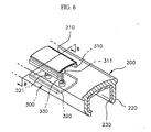
- FIG. 6 is a perspective view showing a state where an engagement opening of the apparatus for fixing the roof rack to the vehicle roof according to the present invention is closed by a movable cover
- FIG. 7 is a sectional view taken along line B-B in FIG. 6.
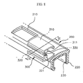
- FIG. 8 is a perspective view showing a state where the engagement opening of the apparatus for fixing the roof rack to the vehicle roof according to the present invention is opened
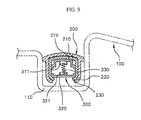
- FIG. 9 is a sectional view taken along line C-C in FIG. 8.
- an apparatus for fixing a roof rack to a vehicle roof comprises a roof panel 100 in which roof molding engagement portions 110 are longitudinally depressed along both sides of the vehicle roof, and roof moldings 200 inserted into and engaged with the roof molding engagement portions 110 of the roof panel 100. Further, according to a technical feature of the present invention, the apparatus comprises engagement openings 210 formed to pass through the roof moldings, and movable covers 300 placed in the interiors of the roof moldings 200 to allow the engagement openings 210 to be resiliently opened and closed.
- each roof molding 200 includes an outer roof molding part 220 and an inner roof molding part 230 inserted into and engaged with an inner circumferential surface of the outer roof molding part 220.
- the engagement openings 210 formed on the roof molding 200 are formed to correspond to the shape of upper cover parts 310 of the movable covers 300 inserted into the roof molding.
- each movable cover 300 is divided into the upper cover part 310, a lower cover part 320 and an elastic member 330.
- the upper cover part 310 is formed to be bent in a multistage form so that a portion of a top surface thereof protrudes upwardly to be inserted into the engagement opening 210, and is provided with at least one cylindrical upper receiving end 311 formed on a bottom surface thereof for receiving the elastic member.
- the lower cover part 320 is provided with at least one cylindrical lower receiving end 321 formed on the top surface thereof for receiving the elastic member.
- both top and bottom ends of the elastic member 330 are inserted into the cylindrical upper receiving end 311 of the upper cover part 310 and the cylindrical lower receiving end 321 of the lower cover part 320, respectively, to resiliently support the movable cover 300 in a vertical direction.
- the movable cover 300 which comprises the upper cover part 310, the lower cover part 320 and the elastic member 330 of which both the ends are inserted, respectively, into the cylindrical upper receiving end 311 of the upper cover part 310 and the cylindrical lower receiving end 321 of the lower cover part 320, is guided into the inner roof molding 230 so that it can move within the roof molding 200 in a fore and aft direction.
- the upper cover part 310 protrudes upwardly by the elastic member 330 of the movable cover 300 to close the engagement opening 210.
- the movable cover 300 is caused to move toward the engagement opening 210 of the roof molding 200. Then, since the upper cover part 310 of the movable cover 300 closes the engagement opening 210 by means of the elastic member 330, the aesthetic appearance of the roof molding can be enhanced.
- the engagement opening 210 of the roof molding 200 is opened since by pressing the upper cover part 310 of the movable cover 300 by which the engagement opening 210 of the roof molding 200 is covered and then moving the movable cover 300 in the fore or aft direction.
- the unified single roof molding can be employed by structurally improving the vehicle roof, irrespective of whether or not the roof rack is used, the number of parts and the cost of production can be reduced and production processes can be simplified. Further, since the roof rack can be easily mounted to and dismounted from the roof molding, a user's convenience increases. Furthermore, since the interior of the roof molding cannot be seen when the roof rack has been dismounted from the roof molding, the aesthetic appearance of the vehicle roof can be enhanced.
Landscapes
- Engineering & Computer Science (AREA)
- Mechanical Engineering (AREA)
- Fittings On The Vehicle Exterior For Carrying Loads, And Devices For Holding Or Mounting Articles (AREA)
- Vehicle Interior And Exterior Ornaments, Soundproofing, And Insulation (AREA)
Abstract
Description
- The present invention relates to an apparatus for fixing a roof rack to a vehicle roof. Particularly, the present invention relates to an apparatus for facilitating mounting and dismounting of a roof rack for loading various kinds of freight thereon by structurally improving a vehicle roof to employ a unified single roof molding, by which the number of parts and the cost of production can be reduced and production processes can be simplified since the unified single roof molding can be employed irrespective of whether or not the roof rack is used, a user's convenience increases since the roof rack can be easily mounted to and dismounted from the roof molding, and the aesthetic appearance of the vehicle roof can be enhanced since the interior of the roof molding cannot be seen when the roof rack has been dismounted therefrom.
- Generally, a vehicle roof is provided with roof moldings for preventing welded portions between a roof panel and a side panel from being exposed to the outside. Such a roof molding is also referred to as a roof carrier. In addition, a roof rack for loading various kinds of freight thereon may be mounted to the roof molding.
- FIG. 1 is a perspective view of a conventional vehicle roof, FIG. 2 is a perspective view of a conventional apparatus for fixing a roof rack to the vehicle roof, and FIG. 3 is a sectional view taken along line A-A in FIG. 1.
- In addition, FIG. 4 is a perspective view of a roof molding of the conventional apparatus for fixing the roof rack to the vehicle roof.
- As shown in FIGS. 1 to 4, the conventional apparatus for fixing the roof rack to the vehicle roof comprises a
roof panel 10 in which roofmolding engagement portions 11 are longitudinally depressed along both sides of the vehicle roof, androof moldings 20 inserted into and engaged with the roofmolding engagement portions 11 of theroof panel 10. - According to the conventional apparatus for fixing the roof rack to the vehicle roof constructed as such, since the integrally formed
roof moldings 20 are longitudinally mounted on both sides of theroof panel 10 as shown in FIG.1 theroof rack 40 cannot be mounted to the roof moldings. On the other hand, since the roof moldings 20 with two ormore engagement openings 30 formed therein are mounted on both sides of theroof panel 10 as shown in FIG. 2, theroof rack 40 can be mounted to the roof moldings through theengagement openings 30. - As shown in FIGS. 3 and 4, the
roof moldings 20 are inserted into and engaged with the roofmolding engagement portions 11 formed to be depressed in theroof panel 10. Eachroof molding 20 includes an outerroof molding part 21 made of synthetic resin, and an innerroof molding part 22 made of stainless steel which is inserted into and engaged with an inner circumferential surface of the outerroof molding part 21. The outerroof molding part 21 enhances the aesthetic appearance of the vehicle roof and also prevents foreign matter from being introduced into the roofmolding engagement portion 11, while the innerroof molding part 22 serves to maintain the strength of theroof molding 20. - However, in the conventional apparatus for fixing the roof rack to the vehicle roof, different kinds of the roof moldings should be used depending on whether or not the roof rack is used. That is, integral type of roof moldings are used in a vehicle in which the roof rack is not employed, whereas separate type of roof moldings are used in a vehicle in which the roof rack is employed. As a result, a unified roof molding cannot be employed regardless of the kinds of vehicles. Further, since the separate type of roof moldings should be used in a case of the vehicle where the roof rack is used, the number of parts and the cost of production may be increased. Furthermore, there is a technical problem in that the user cannot have an alternative to employing the roof rack according to a user's will.
- The present invention is contemplated to solve the above problems. It is an object of the present invention to provide an apparatus for fixing a roof rack to a vehicle roof, by which the number of parts and the cost of production can be reduced and production processes can be simplified since a unified single roof molding can be employed by structurally improving the vehicle roof, irrespective of whether or not the roof rack is used, a user's convenience increases since the roof rack can be easily mounted to and dismounted from the roof molding, and the aesthetic appearance of the vehicle roof can be enhanced since the interior of the roof molding cannot be seen upon when the roof rack has been dismounted therefrom.
- In order to accomplish the above object of the present invention, there is provided an improved apparatus for fixing a roof rack to a vehicle roof of the type comprising a roof panel in which roof molding engagement portions are longitudinally depressed along both sides of the vehicle roof, and roof moldings inserted into and engaged with the roof molding engagement portions of the roof panel. Further, the apparatus of the present invention comprises engagement openings formed to pass through the roof moldings, and movable covers placed in the interiors of the roof moldings to allow the engagement openings to be resiliently opened and closed.
- The above and other objects and features of the present invention will become apparent from the following description of a preferred embodiment given in conjunction with the accompanying drawings, in which:
- FIG. 1 is a perspective view of a conventional vehicle roof;
- FIG. 2 is a perspective view of a conventional apparatus for fixing a roof rack to the vehicle roof;
- FIG. 3 is a sectional view taken along line A-A in FIG. 1;
- FIG. 4 is a perspective view of a roof molding of the conventional apparatus for fixing the roof rack to the vehicle roof;
- FIG. 5 is an exploded perspective view of an apparatus for fixing a roof rack to a vehicle roof according to the present invention;
- FIG. 6 is a perspective view showing a state where an engagement opening of the apparatus for fixing the roof rack to the vehicle roof according to the present invention is closed by a movable cover;
- FIG. 7 is a sectional view taken along line B-B in FIG. 6;
- FIG. 8 is a perspective view showing a state where the engagement opening of the apparatus for fixing the roof rack to the vehicle roof according to the present invention is opened; and
- FIG. 9 is a sectional view taken along line C-C in FIG. 8.
-
- The constitution of a preferred embodiment of the present invention will be explained in detail with reference to the accompanying drawings.
- FIG. 5 is an exploded perspective view of an apparatus for fixing a roof rack to a vehicle roof according to the present invention, FIG. 6 is a perspective view showing a state where an engagement opening of the apparatus for fixing the roof rack to the vehicle roof according to the present invention is closed by a movable cover, and FIG. 7 is a sectional view taken along line B-B in FIG. 6.
- Further, FIG. 8 is a perspective view showing a state where the engagement opening of the apparatus for fixing the roof rack to the vehicle roof according to the present invention is opened, and FIG. 9 is a sectional view taken along line C-C in FIG. 8.
- As shown in FIGS. 5 to 9, an apparatus for fixing a roof rack to a vehicle roof according to the present invention comprises a
roof panel 100 in which roofmolding engagement portions 110 are longitudinally depressed along both sides of the vehicle roof, androof moldings 200 inserted into and engaged with the roofmolding engagement portions 110 of theroof panel 100. Further, according to a technical feature of the present invention, the apparatus comprisesengagement openings 210 formed to pass through the roof moldings, andmovable covers 300 placed in the interiors of theroof moldings 200 to allow theengagement openings 210 to be resiliently opened and closed. - As shown in FIG. 5, each
roof molding 200 includes an outerroof molding part 220 and an innerroof molding part 230 inserted into and engaged with an inner circumferential surface of the outerroof molding part 220. Theengagement openings 210 formed on theroof molding 200 are formed to correspond to the shape ofupper cover parts 310 of themovable covers 300 inserted into the roof molding. - Further, each
movable cover 300 is divided into theupper cover part 310, alower cover part 320 and anelastic member 330. Theupper cover part 310 is formed to be bent in a multistage form so that a portion of a top surface thereof protrudes upwardly to be inserted into theengagement opening 210, and is provided with at least one cylindrical upper receivingend 311 formed on a bottom surface thereof for receiving the elastic member. Thelower cover part 320 is provided with at least one cylindrical lower receivingend 321 formed on the top surface thereof for receiving the elastic member. - Therefore, both top and bottom ends of the
elastic member 330 are inserted into the cylindrical upper receivingend 311 of theupper cover part 310 and the cylindrical lower receivingend 321 of thelower cover part 320, respectively, to resiliently support themovable cover 300 in a vertical direction. - At this time, the
movable cover 300, which comprises theupper cover part 310, thelower cover part 320 and theelastic member 330 of which both the ends are inserted, respectively, into the cylindrical upper receivingend 311 of theupper cover part 310 and the cylindrical lower receivingend 321 of thelower cover part 320, is guided into theinner roof molding 230 so that it can move within theroof molding 200 in a fore and aft direction. - Hereinafter, the operation and effects of the present invention will be explained with reference to FIGS. 5 to 9.
- As described above, when the
movable cover 300 is placed in the engagement opening 210 formed on theroof molding 200, theupper cover part 310 protrudes upwardly by theelastic member 330 of themovable cover 300 to close the engagement opening 210. - Therefore, when the roof rack (not shown) needs not to be mounted to the
roof molding 200, as shown in FIGS. 6 and 7, themovable cover 300 is caused to move toward the engagement opening 210 of theroof molding 200. Then, since theupper cover part 310 of themovable cover 300 closes the engagement opening 210 by means of theelastic member 330, the aesthetic appearance of the roof molding can be enhanced. - On the contrary, when the roof rack needs to be mounted to the
roof molding 200, the engagement opening 210 of theroof molding 200 is opened since by pressing theupper cover part 310 of themovable cover 300 by which the engagement opening 210 of theroof molding 200 is covered and then moving themovable cover 300 in the fore or aft direction. - As described above, according to the present invention, since the unified single roof molding can be employed by structurally improving the vehicle roof, irrespective of whether or not the roof rack is used, the number of parts and the cost of production can be reduced and production processes can be simplified. Further, since the roof rack can be easily mounted to and dismounted from the roof molding, a user's convenience increases. Furthermore, since the interior of the roof molding cannot be seen when the roof rack has been dismounted from the roof molding, the aesthetic appearance of the vehicle roof can be enhanced.
Claims (3)
- An improved apparatus for fixing a roof rack to a vehicle roof of the type comprising a roof panel in which roof molding engagement portions are longitudinally formed to be depressed along both sides of the vehicle roof, and roof moldings inserted into and engaged with the roof molding engagement portions of the roof panel, wherein the improvement comprises:engagement openings formed to pass through the roof moldings; andmovable covers placed in the interiors of the roof moldings to allow the engagement openings to be resiliently opened and closed.
- The apparatus as claimed in claim 1, wherein each movable cover includes an upper cover part which is bent in a multistage form so that a portion of a top surface thereof protrudes upwardly to be inserted into the engagement opening, and is provided with at least one cylindrical upper receiving end formed on a bottom surface thereof for receiving an elastic member, a lower cover part provided with at least one cylindrical lower receiving end formed on a top surface thereof for receiving the elastic member, and the elastic member with both ends thereof inserted into the cylindrical upper and lower receiving ends, respectively.
- The apparatus as claimed in claim 1, wherein each roof molding includes an outer roof molding part, and an inner roof molding part inserted into and engaged with an inner circumferential surface of the outer roof molding part.
Applications Claiming Priority (2)
| Application Number | Priority Date | Filing Date | Title |
|---|---|---|---|
| KR2001050603 | 2001-08-22 | ||
| KR10-2001-0050603A KR100448404B1 (en) | 2001-08-22 | 2001-08-22 | Apparatus for fixing a roof rack of vehicles |
Publications (1)
| Publication Number | Publication Date |
|---|---|
| EP1285816A1 true EP1285816A1 (en) | 2003-02-26 |
Family
ID=19713442
Family Applications (1)
| Application Number | Title | Priority Date | Filing Date |
|---|---|---|---|
| EP01130977A Withdrawn EP1285816A1 (en) | 2001-08-22 | 2001-12-28 | Covering strip for vehicle roof rack channel |
Country Status (5)
| Country | Link |
|---|---|
| US (1) | US6568748B2 (en) |
| EP (1) | EP1285816A1 (en) |
| JP (1) | JP3600880B2 (en) |
| KR (1) | KR100448404B1 (en) |
| CN (1) | CN1401518A (en) |
Cited By (5)
| Publication number | Priority date | Publication date | Assignee | Title |
|---|---|---|---|---|
| KR100448404B1 (en) * | 2001-08-22 | 2004-09-13 | 기아자동차주식회사 | Apparatus for fixing a roof rack of vehicles |
| EP1498318A3 (en) * | 2003-07-14 | 2005-04-13 | Hashimoto Forming Industry Co., Ltd. | Vehicle roof molding |
| DE102008011939B3 (en) * | 2008-02-29 | 2009-08-27 | A. Raymond Et Cie | Sliding cover arrangement for cover strip of roof duct of motor vehicle, has contact between bearing unit and retaining unit, which is released by moving sliding cover from fastening position into releasing position |
| CN105291999A (en) * | 2015-11-11 | 2016-02-03 | 宁波信泰机械有限公司 | Improved structure of automobile luggage rack aluminum pipe installation hole covering assembly |
| WO2018153537A1 (en) * | 2017-02-21 | 2018-08-30 | Sapa Components Uk | A vehicle roof rail and a method for manufacturing a roof rail |
Families Citing this family (31)
| Publication number | Priority date | Publication date | Assignee | Title |
|---|---|---|---|---|
| DE60103850T2 (en) * | 2000-02-04 | 2005-09-29 | Decoma International Inc., Concord | ONE-PIECE SHAPED ROOF RACK |
| US20030108286A1 (en) * | 2001-12-06 | 2003-06-12 | Jacques Albert | Adjustable temperature compensating package for optical fiber devices |
| DE10210141A1 (en) * | 2002-03-07 | 2003-09-18 | Arvinmeritor Gmbh | Body part and method for its production |
| US7004537B2 (en) * | 2004-02-27 | 2006-02-28 | Sport Carriers, Inc. | Molding apparatus for vehicles and methods for use |
| DE102004044159A1 (en) * | 2004-09-13 | 2006-03-16 | Arvinmeritor Gmbh | Composite component, in particular body attachment for a vehicle, and method for producing such a composite component |
| US7004535B1 (en) * | 2004-12-06 | 2006-02-28 | Nissan Technical Center North America, Inc. | Roof ditch molding fastener |
| US7029060B1 (en) * | 2004-12-06 | 2006-04-18 | Nissan Technical Center North America, Inc. | Roof ditch molding structure |
| KR100598855B1 (en) * | 2005-01-20 | 2006-07-11 | 기아자동차주식회사 | Roof Rack Mounting Device |
| KR100747867B1 (en) * | 2005-10-28 | 2007-08-08 | 기아자동차주식회사 | Roof molding structure for roof rack assembly |
| KR100706421B1 (en) * | 2005-12-08 | 2007-04-10 | 기아자동차주식회사 | Roof molding cover device for roof rack assembly |
| US7635209B2 (en) * | 2006-01-27 | 2009-12-22 | Honda Motor Co., Ltd. | Lamp for vehicle and lamp-mounted vehicle |
| WO2007107968A1 (en) * | 2006-03-22 | 2007-09-27 | Sportrack Llc | Vehicle roof ditch cover attachment clip |
| US20070235485A1 (en) * | 2006-03-28 | 2007-10-11 | Ford Global Technologies, Llc | System for mounting an automotive accessory |
| US7641250B2 (en) * | 2007-04-27 | 2010-01-05 | Toyota Motor Engineering & Manufacturing North America, Inc. | Body molding with integral lock for a vehicle |
| KR100877784B1 (en) | 2007-12-14 | 2009-01-08 | 현대자동차주식회사 | Rotary roof molding cover device |
| DE102008064346B4 (en) * | 2008-12-20 | 2020-10-08 | Dr. Ing. H.C. F. Porsche Aktiengesellschaft | Device for attaching a roof rack system |
| US20120074187A1 (en) * | 2010-09-27 | 2012-03-29 | Gm Global Technology Operations, Inc. | Deployable roof rack system |
| CN102874179B (en) * | 2011-07-13 | 2015-01-14 | 双馀实业有限公司 | Roof Rack Fixtures |
| US9022264B2 (en) | 2012-11-14 | 2015-05-05 | GM Global Technology Operations LLC | Reconfigurable roof rack attachment assembly for a vehicle |
| US8966795B1 (en) | 2013-11-04 | 2015-03-03 | Michael Shipman | Vehicle roof plate |
| CN103707816A (en) * | 2013-12-27 | 2014-04-09 | 宁波敏实汽车零部件技术研发有限公司 | Covering device for aluminum tube installing hole of automobile roof rack |
| GB2533383A (en) * | 2014-12-18 | 2016-06-22 | Bentley Motors Ltd | Roof rail |
| JP6434823B2 (en) * | 2015-02-27 | 2018-12-05 | 片山工業株式会社 | Roof molding cap mounting structure and roof molding |
| KR101683510B1 (en) * | 2015-04-07 | 2016-12-08 | 현대자동차 주식회사 | Roof rack structure |
| CN105083139B (en) * | 2015-09-24 | 2017-10-31 | 广东东箭汽车科技股份有限公司 | A kind of automobile and its roof-rack |
| CN107187396A (en) * | 2017-04-29 | 2017-09-22 | 佛山市维杰汽车部件制造有限公司 | Roof-rack |
| USD856262S1 (en) * | 2018-02-13 | 2019-08-13 | Greg Marankie | Roof rack |
| USD883182S1 (en) * | 2018-09-10 | 2020-05-05 | Expedition One, LLC | Vehicle rack system |
| US11142131B2 (en) * | 2019-05-15 | 2021-10-12 | Bestop Aluminess, Llc | Modular roof rack system |
| DE102021203240A1 (en) | 2021-03-30 | 2022-10-06 | Motherson Innovations Company Limited | Vehicle trim strip assembly for a vehicle |
| CN116872849A (en) * | 2023-07-24 | 2023-10-13 | 宁波信泰机械有限公司 | Color separation luggage rack and automobile |
Citations (4)
| Publication number | Priority date | Publication date | Assignee | Title |
|---|---|---|---|---|
| GB2208755A (en) * | 1983-12-23 | 1989-04-12 | Robert Edward Mcfarland | A limit switch and shock-absorber |
| EP0730998A1 (en) * | 1995-03-10 | 1996-09-11 | Schade Kg | Covering strip assembly for a vehicle roof rack channel |
| EP0827869A1 (en) * | 1996-09-05 | 1998-03-11 | Automobiles Peugeot | Decorative covering for a vehicle roofrack channel |
| DE19840295A1 (en) * | 1998-09-04 | 2000-03-09 | Silvatrim Sa | Cover strip for recess in vehicle roof for roof rack support foot, with slide support element fixed in it |
Family Cites Families (18)
| Publication number | Priority date | Publication date | Assignee | Title |
|---|---|---|---|---|
| US4473178A (en) * | 1981-02-27 | 1984-09-25 | Bott John Anthony | Vehicle luggage carrier |
| US4767040A (en) * | 1987-04-09 | 1988-08-30 | Miller Dennis J | Snap-in end cap for article carriers |
| US5002216A (en) * | 1987-07-16 | 1991-03-26 | Gerber Group Ltd. | Invisible mount roof rack |
| US5016798A (en) * | 1990-04-05 | 1991-05-21 | Huron/St. Clair Incorporated | Spacer insert for load-bearing slats |
| US5090605A (en) * | 1990-11-06 | 1992-02-25 | John A. Bott | Slat assembly for vehicle article carriers |
| JP3318046B2 (en) * | 1993-06-03 | 2002-08-26 | 株式会社東郷製作所 | Mall cover |
| WO1995007196A1 (en) * | 1993-09-10 | 1995-03-16 | Mascotech Accessories, Inc. | Vehicular rack slat securance |
| US5636776A (en) * | 1995-06-30 | 1997-06-10 | Rak; Arthur K. | Vehicle article carrier having slats with concealable cross bar mounting portions |
| KR0132509Y1 (en) * | 1996-04-30 | 1998-12-15 | 양재신 | Roof rack fixing structure on vehicle roof |
| US5762247A (en) * | 1996-05-02 | 1998-06-09 | Jac Products, Inc. | Vehicle article carrier |
| US5918929A (en) * | 1996-05-31 | 1999-07-06 | Vagis; Brock | Device for attaching accessories to the roof of a motor vehicle |
| KR0175274B1 (en) * | 1996-10-09 | 1999-04-01 | 삼성전자주식회사 | Chiens searching apparatus for reed solomon decoder |
| DE19716048C1 (en) * | 1997-04-17 | 1998-12-10 | Porsche Ag | Fastening device for roof rack on motor vehicles, in particular passenger cars |
| CA2269907A1 (en) * | 1998-04-20 | 1999-10-20 | Decoma International Inc. | Article carrier for a vehicle |
| US5975391A (en) * | 1998-04-22 | 1999-11-02 | Jac Products, Inc. | Mounting member for a slat of a vehicle article carrier |
| JP2000103298A (en) * | 1998-09-29 | 2000-04-11 | Kanto Auto Works Ltd | Roof molding installing structure |
| US6311882B1 (en) * | 2000-05-09 | 2001-11-06 | Jac Products, Inc. | Adaptor for mounting a slat over a roof ditch in a vehicle roof |
| KR100448404B1 (en) * | 2001-08-22 | 2004-09-13 | 기아자동차주식회사 | Apparatus for fixing a roof rack of vehicles |
-
2001
- 2001-08-22 KR KR10-2001-0050603A patent/KR100448404B1/en not_active Expired - Fee Related
- 2001-12-26 JP JP2001395504A patent/JP3600880B2/en not_active Expired - Fee Related
- 2001-12-28 EP EP01130977A patent/EP1285816A1/en not_active Withdrawn
- 2001-12-28 US US10/028,287 patent/US6568748B2/en not_active Expired - Lifetime
- 2001-12-31 CN CN01145315A patent/CN1401518A/en active Pending
Patent Citations (4)
| Publication number | Priority date | Publication date | Assignee | Title |
|---|---|---|---|---|
| GB2208755A (en) * | 1983-12-23 | 1989-04-12 | Robert Edward Mcfarland | A limit switch and shock-absorber |
| EP0730998A1 (en) * | 1995-03-10 | 1996-09-11 | Schade Kg | Covering strip assembly for a vehicle roof rack channel |
| EP0827869A1 (en) * | 1996-09-05 | 1998-03-11 | Automobiles Peugeot | Decorative covering for a vehicle roofrack channel |
| DE19840295A1 (en) * | 1998-09-04 | 2000-03-09 | Silvatrim Sa | Cover strip for recess in vehicle roof for roof rack support foot, with slide support element fixed in it |
Cited By (5)
| Publication number | Priority date | Publication date | Assignee | Title |
|---|---|---|---|---|
| KR100448404B1 (en) * | 2001-08-22 | 2004-09-13 | 기아자동차주식회사 | Apparatus for fixing a roof rack of vehicles |
| EP1498318A3 (en) * | 2003-07-14 | 2005-04-13 | Hashimoto Forming Industry Co., Ltd. | Vehicle roof molding |
| DE102008011939B3 (en) * | 2008-02-29 | 2009-08-27 | A. Raymond Et Cie | Sliding cover arrangement for cover strip of roof duct of motor vehicle, has contact between bearing unit and retaining unit, which is released by moving sliding cover from fastening position into releasing position |
| CN105291999A (en) * | 2015-11-11 | 2016-02-03 | 宁波信泰机械有限公司 | Improved structure of automobile luggage rack aluminum pipe installation hole covering assembly |
| WO2018153537A1 (en) * | 2017-02-21 | 2018-08-30 | Sapa Components Uk | A vehicle roof rail and a method for manufacturing a roof rail |
Also Published As
| Publication number | Publication date |
|---|---|
| JP2003072475A (en) | 2003-03-12 |
| US20030038510A1 (en) | 2003-02-27 |
| US6568748B2 (en) | 2003-05-27 |
| JP3600880B2 (en) | 2004-12-15 |
| CN1401518A (en) | 2003-03-12 |
| KR20030016831A (en) | 2003-03-03 |
| KR100448404B1 (en) | 2004-09-13 |
Similar Documents
| Publication | Publication Date | Title |
|---|---|---|
| US6568748B2 (en) | Apparatus for fixing roof rack to vehicle roof | |
| US5797642A (en) | Luggage compartment construction | |
| CN1991125B (en) | Door structure for vehicles | |
| KR101703143B1 (en) | console arm rest device having guide unit for noise prevention | |
| US9845055B2 (en) | Vehicle center console assembly | |
| US8714614B2 (en) | Instrument panel | |
| IE54828B1 (en) | Resilient detented lid latch | |
| WO1995023011A2 (en) | Seat belt web guide | |
| US20050012321A1 (en) | Deflection fitting for a safety belt | |
| US20040084451A1 (en) | Cover for closing an opening in a wall | |
| US7367103B2 (en) | Method of forming a vehicle component | |
| US5478126A (en) | Vehicle storage compartment latch assembly with anti-rattle device | |
| US6299236B1 (en) | Interior lining, and door fitted therewith, comprising a means for limiting the displacement of a window at least in one direction | |
| US20060038422A1 (en) | Guide structure of a tray | |
| JP3318046B2 (en) | Mall cover | |
| US5639146A (en) | Wheel cover mounting structure | |
| GB2294911A (en) | Wheel and wheel trim assembly | |
| JP3747384B2 (en) | Tire case | |
| JP2688033B2 (en) | Console Box | |
| EP4212370B1 (en) | Vehicle tailgate assembly and vehicle | |
| US11584462B2 (en) | Panel standoff and stopper hole | |
| CN211493781U (en) | Vehicle-mounted cup stand | |
| KR100449296B1 (en) | A luggage mat of an automobile | |
| KR200144232Y1 (en) | Self side trim of car | |
| JP3855154B2 (en) | Glass run in elevating glass guide structure |
Legal Events
| Date | Code | Title | Description |
|---|---|---|---|
| PUAI | Public reference made under article 153(3) epc to a published international application that has entered the european phase |
Free format text: ORIGINAL CODE: 0009012 |
|
| AK | Designated contracting states |
Kind code of ref document: A1 Designated state(s): AT BE CH CY DE DK ES FI FR GB GR IE IT LI LU MC NL PT SE TR Designated state(s): AT BE CH CY DE DK ES FI FR GB GR IE IT LI LU MC NL PT SE TR |
|
| AX | Request for extension of the european patent |
Extension state: AL LT LV MK RO SI |
|
| 17P | Request for examination filed |
Effective date: 20030826 |
|
| AKX | Designation fees paid |
Designated state(s): DE FR GB |
|
| 17Q | First examination report despatched |
Effective date: 20040630 |
|
| STAA | Information on the status of an ep patent application or granted ep patent |
Free format text: STATUS: THE APPLICATION IS DEEMED TO BE WITHDRAWN |
|
| 18D | Application deemed to be withdrawn |
Effective date: 20041111 |