EP1285801A2 - Convertible vehicle with a rigid rear roof element - Google Patents
Convertible vehicle with a rigid rear roof element Download PDFInfo
- Publication number
- EP1285801A2 EP1285801A2 EP02017988A EP02017988A EP1285801A2 EP 1285801 A2 EP1285801 A2 EP 1285801A2 EP 02017988 A EP02017988 A EP 02017988A EP 02017988 A EP02017988 A EP 02017988A EP 1285801 A2 EP1285801 A2 EP 1285801A2
- Authority
- EP
- European Patent Office
- Prior art keywords
- roof
- area
- roof part
- vehicle
- rear roof
- Prior art date
- Legal status (The legal status is an assumption and is not a legal conclusion. Google has not performed a legal analysis and makes no representation as to the accuracy of the status listed.)
- Granted
Links
Images


Classifications
-
- B—PERFORMING OPERATIONS; TRANSPORTING
- B60—VEHICLES IN GENERAL
- B60J—WINDOWS, WINDSCREENS, NON-FIXED ROOFS, DOORS, OR SIMILAR DEVICES FOR VEHICLES; REMOVABLE EXTERNAL PROTECTIVE COVERINGS SPECIALLY ADAPTED FOR VEHICLES
- B60J7/00—Non-fixed roofs; Roofs with movable panels, e.g. rotary sunroofs
- B60J7/0053—Collapsible lateral roof side beams
- B60J7/0069—Collapsible lateral roof side beams where the beam itself is folded and moves inwardly, e.g. concertina type
Definitions
- the invention relates to a convertible vehicle with a rigid rear roof part according to the preamble of claim 1.
- the invention is therefore based on the problem of creating a convertible vehicle, that offers the advantages of a rigid rear roof part and yet the lowest possible Pack size for the deposited roof is reached.
- the invention solves the problem with a convertible vehicle with the features of Claim 1.
- Advantageous refinements result from the subclaims 2 to 8.
- the front roof area at least partially under the rear roof part can be moved and stored with this; can be the length of the filed Package essentially determined by the length of the rear roof part be, whereby the space requirement of the stored roof is particularly low is. This is especially true if the front roof area is completely under the rear roof part is relocatable.
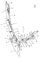
- the convertible vehicle 1 includes a
- the first frame part 4 extends from a windshield frame 6 or a fixed front transverse end 36 of the roof to one between the frame parts 4, 5 lying parting line 7.
- the rear frame part extends from the parting line 7 to the rear roof part 2.
- the frame parts are by cross brackets 9, 10, 11 connected to each other. Above this is a total of 12 Roof covering stretched.
- the rear bow 11 is in the closed state held directly in front of the rear roof part 2 and forms a kind of tension bar for the rear end 13 of the roof covering 12.
- a front Synchronization linkage 8 is provided, like the bow 9, 10, 11 the roof covering 12 runs under. This allows for the shortening of the roof described below smooth movement of the two sides of the roof parallel to the vehicle's longitudinal direction can be achieved.
- each side of the vehicle 14 - here designed as a hydraulic cylinder - arranged from the bow 11 extends up to a joint 15 which is arranged in the region of the parting line 7 and can be swung open about at least one vertical axis 16.
- the drive member 14 is covered by the cover 12. Its front end is further towards one vertical median longitudinal plane displaced as its rear end.
- the joint 15 is with the side frame parts 4, 5 in the vicinity of the division joint 7 connected.
- the front frame part 4 is in one in the course of its longitudinal extent from the parting line 7 area on the joint 17 divided into the respect a vertical vehicle longitudinal plane non-swiveling front section 4a and in contrast about a vertical axis 18 of the joint 17 in In the direction of the vertical median longitudinal plane 19 pivoting section 4b.
- the rear frame part 5 is also in the course of its longitudinal extent an area distant from the parting line 7 on the joint 20 divided into the with respect to a vertical vehicle longitudinal plane non-swiveling rear section 5a and, in contrast, about a vertical axis 21 of the joint 20 in the direction the vertical vehicle longitudinal center plane 19 pivotable section 5b.
- the rear roof part 2 and the flexible roof part 3 form in every phase of their movement a coherent roof surface that is not - for example in the area the transition from roof part 2 to roof area 3 - interrupted by an open joint is.
- the textile cover 12 can either be attached to the fixed roof part 2 be or overlap it.
- the rear roof part 2 as a whole Glass or plastic dome is formed and with its front edge 22 is connected to the cover 12 without being overlapped by it.
- a central see-through area with a dark, light and / or heat absorbing area Coating should be provided.
- the rear roof part 2 is on a total of 23 linkage on each Vehicle side connected to a main bearing 24, around which the rear Roof part 2 is pivoted about a horizontal axis pointing in the transverse direction of the vehicle can be.
- the linkage 23 comprises two drive members 25, 26.
- Das Drive element 25 is on the piston rod side via a lever Gh with an articulated parallelogram G connected.
- This includes the four parts G1, G2, G3 and G4 that are connected to each other at the swivel joints GS1, GS2, GS3 and GS4.
- the pivot axes of these joints run horizontally and in the transverse direction of the vehicle. With the GS3 and GS4 joints, the four-bar G engages at the rear end of the front roof part, whereby with the actuation of this four-bar G a relative movement between the roof parts 2 and 3 can be effected.
- the drive member 26, engages on the piston rod side on a first link H1 of the second joint parallelogram H.
- the handlebar H1 extends therein parallel to the handlebar H3.
- the handlebars H2 and H4 over the joints HS1 or HS 2 with the handlebar H1 and over the joints HS 3 or HS 4 with the Handlebars H3 are connected.
- the drive members 25, 26 arranged such that with the help of an almost vertical stroke movement of the Roof part 2 is conveyable. The relative movement of the front roof part 3 can in an immobile position of the rear roof part 2 take place.
- a third drive member 27 is provided, which is on a main lever 28 attacks and thereby pivots with a large swivel angle around the main bearing 24 can cause.
- the rear roof part 2 lies with its rear one Edge 35 on a cover part 29.
- This serves both functions to cover the soft top compartment as well as the trunk.
- the cover part 29 in a first sense to release a passage opening for the roof and in a second sense to open a loading opening for the Trunk can be opened.
- the cover part is designed in two parts for this purpose the front part 30 connects to a transverse joint 31 to the rear part 32.
- the Front part 30 is with its front end in the direction of travel F in a longitudinal guide link kept movable and in the area of the transverse joint 31 with the rear Part 32 pivotally connected.
- the rear part 32 is on its rear edge hinged to the vehicle body 33.
- the pivoting movement of the rear part 32 of the lid part 29 is by at least one in the area of the rear Articulation of the rear part 32 located drive member can be effected.
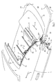
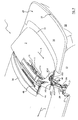
- a first step ( Figures 3 and 4), the rear roof part 2 is raised.
- This lifting can take place as a purely vertical lifting movement.
- the four-bar linkage H is opened by the drive member 26 such that the handlebars H1 and H3 swing around the mentioned joints HS2 and HS3, so that the rear joints HS1 and HS4 held on the rear roof part 2 are panning forward and upward.
- Lifting is done through the joint parallelogram designed as a combination movement of lifting and swiveling movement.
- the roof part 2 is pushed to a small extent over the flexible roof area 3, whereby the cover 12 can relax.
- the top compartment lid 29 can be opened become.
- its rear-side part 32 is replaced by the assigned one or more Drive elements - not shown - swung open relative to the body 33.
- the part 32 By coupling the part 32 to a front part 30 of the top compartment lid 29 this is pulled against the direction of travel F. there the front end of the front part 30 is held in a longitudinal guide link.
- the pulling movement on the front part 31 therefore causes lifting at the same time its leading edge. Its rear edge is opened by swinging the back Part 32 raised more clearly and at the same time rearward under the rear Roof part 2 pulled away. In this phase of movement, in adaptation to this circumferential rear edge 35 of the rear roof part 2 slightly rearward upward posed. Overall, the must to enable the top compartment lid opening rear roof part 2 can only be raised by a small amount. The overall movement is accelerated.
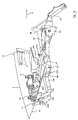
- the roof is opened by actuating the drive element 27 pivoted a little way to the rear via the main lever 28 (FIGS. 5 and 6), which increases the headroom for the occupants.
- the whole flexible roof area 3 in the not shortened state by actuation of the drive member 25 rearwards in the direction under the rear roof part 2.
- the fold-in movement of the flexible roof area begins from this position 3 ( Figures 7 to 10).
- the drive members 25, 26 and 27 can be constant Position remain.
- the substantially horizontally located drive member 14 is attracted, whereby the joint 15, which in the exemplary embodiment as a horizontal and pivotable about a vertical axis like a scissor lattice trained seven-joint is formed, is opened. This is with the front side frame part 4 and with the rear frame part 5 each connected in the vicinity of the parting line 7 and exerts a torque thereon out. This pulls the sections 4b and 5b in the direction of the vertical median longitudinal plane 19 inwards.
- the section 4b pivots opposite the front section 4a maintaining its longitudinal orientation around the vertical Axis 18 of the joint 17 a; the section 5b of the rear frame part 5 pivots against its rear, maintaining its longitudinal orientation Section 5a around the vertical axis 21 of the joint 20.
- the sections 4b, 5b are so far around the joints by the drive member 14 17 or 20 pivoted in that at the end of the roof shortening (Fig. 11, Fig. 12) extend substantially completely in the vehicle transverse direction.
- the division joint 7 is then close to the vertical median longitudinal plane 19.
- the drive member 14 is also pivoted into a position pointing transversely to the direction of travel F. Service.
- the length of the package thus formed is extraordinary low and is essentially determined by the length of the rear rigid roof part 2.
- the roof covering can be in its individual areas are close to each other without bow or the like the minimum height of the would limit the resulting package.
- the resulting package which is delimited on the top by the rigid roof part 2, is by extending the drive member 27 and swinging open of the main lever 28 in an almost horizontal position (Fig. 13 to 16) rearward pivoted and placed below the window sill line in such a way that even in the closed position, the rigid rear roof part the stored roof limited upwards.
Landscapes
- Engineering & Computer Science (AREA)
- Mechanical Engineering (AREA)
- Body Structure For Vehicles (AREA)
Abstract
Description
Die Erfindung betrifft ein Cabriolet-Fahrzeug mit einem starren hinteren Dachteil
nach dem Oberbegriff des Anspruchs 1.The invention relates to a convertible vehicle with a rigid rear roof part
according to the preamble of
Es ist bekannt, derartige Cabriolet-Fahrzeuge mit einem aus mehreren festen Dachteilen bestehenden Dach zu versehen. Beispielsweise schließt sich an das hintere Dachteil ein in geschlossener Stellung im wesentlichen horizontal angeordnetes vorderes Dachteil an, das zum Öffnen des Daches gegen das hintere Dachteil einschwenkt, so daß das Paket aus den beiden dann im wesentlichen parallel zueinanderliegenden Dachteilen im rückwärtigen Fahrzeugbereich aufgenommen werden kann.It is known that such convertible vehicles with one of several fixed Roof parts to provide existing roof. For example, that follows rear roof part a substantially horizontally arranged in the closed position front part of the roof to open the roof against the rear part of the roof swings in, so that the package of the two then lying essentially parallel to each other Roof parts in the rear vehicle area are included can.
Ein derartiges Paket aus zwei oder mehr festen Dachteilen nimmt einen erheblichen Raum ein, wodurch der für den Kofferraum verbleibende Karosseriebereich eingeschränkt wird. Insbesondere wenn die Dachteile gegeneinander einwärts verschwenken, kommt es aufgrund der dann gegenläufigen Krümmungen zu einer erheblichen dicken Ausdehnung des abgelegten Paketes. Andererseits eröffnet das starre hintere Dachteil die Möglichkeit, eine Heckscheibe aus Glas zu integrieren, ohne teure Klebe- oder Schweißverbindungen zu umliegenden textilen Randbereichen herstellen zu müssen. Die Montage und Demontage einer Heckscheibe ist daher bei festen Dachteilen erleichtert. Zudem besteht die Möglichkeit, ein hinteres Dachteil vollständig aus Glas oder einem transparenten Kunststoff auszubilden und Bereiche, die nicht durchsichtig sein müssen, mit einer entsprechenden Beschichtung zu versehen.Such a package of two or more fixed roof parts takes a considerable amount Space, which limits the body area remaining for the trunk becomes. Especially when the roof parts swivel inwards towards each other, there is a considerable curvature due to the opposite curvatures thick expansion of the dropped package. On the other hand, that opens up rigid rear roof part the possibility to integrate a glass rear window, without expensive adhesive or welded connections to surrounding textile edge areas to have to manufacture. The assembly and disassembly of a rear window is therefore relieved with fixed roof parts. There is also the possibility of a rear Form roof part completely from glass or a transparent plastic and Areas that do not have to be transparent with a suitable coating to provide.
Der Erfindung liegt daher das Problem zugrunde, ein Cabrioletfahrzeug zu schaffen, das die Vorteile eines starren hinteren Dachteils bietet und dennoch ein geringstmögliches Packmaß für das abgelegte Dach erreicht wird.The invention is therefore based on the problem of creating a convertible vehicle, that offers the advantages of a rigid rear roof part and yet the lowest possible Pack size for the deposited roof is reached.
Die Erfindung löst das Problem durch ein Cabrioletfahrzeug mit den Merkmalen des
Anspruchs 1. Vorteilhafte Ausgestaltungen ergeben sich aus den Unteransprüchen
2 bis 8.The invention solves the problem with a convertible vehicle with the features of
Mit der Ausbildung eines flexiblen vorderen Dachbereichs kann dieser in ein kleines Packmaß zusammengefaltet werden. Dennoch kann aufgrund des starren hinteren Dachteils die Heckscheibe in der erwähnten einfachen Weise montiert und demontiert werden. Die Vorteile eines Festdachs und eines flexiblen Dachs sind daher erfindungsgemäß kombiniert.With the formation of a flexible front roof area, this can be converted into a small one Pack size can be folded. Still, due to the rigid rear Roof part, the rear window assembled and disassembled in the simple manner mentioned become. The advantages of a fixed roof and a flexible roof are therefore according to the invention combined.
Wenn besonders vorteilhaft der vordere Dachbereich zumindest teilweise unter das hintere Dachteil verlagerbar und mit diesem ablegbar ist; kann die Länge des abgelegten Pakets im wesentlichen durch das Längsausmaß des hinteren Dachteils bestimmt werden, wodurch der Platzbedarf des abgelegten Daches besonders gering ist. Dies gilt insbesondere, wenn der vordere Dachbereich vollständig unter das hintere Dachteil verlagerbar ist.If particularly advantageous, the front roof area at least partially under the rear roof part can be moved and stored with this; can be the length of the filed Package essentially determined by the length of the rear roof part be, whereby the space requirement of the stored roof is particularly low is. This is especially true if the front roof area is completely under the rear roof part is relocatable.
Weitere Vorteile und Merkmale der Erfindung ergeben sich aus einem nachfolgend beschriebenen und in der Zeichnung dargestellten Ausführungsbeispiel der Erfindung, bei dem das vordere, flexible Dachteil sich von dem starren Dachteil bis zu einem Windschutzscheibenrahmen erstreckt, was nicht zwingend ist, und in Längsrichtung verkürzbar ist, was ebenfalls nicht unbedingt erforderlich ist.Further advantages and features of the invention result from the following described embodiment of the invention and shown in the drawing, in which the front, flexible roof part extends from the rigid roof part to a windshield frame, which is not mandatory, and in the longitudinal direction can be shortened, which is also not absolutely necessary.
In der Zeichnung zeigt:
- Fig. 1
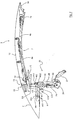
- eine perspektivische Ansicht von schräg hinten auf einen mittleren Teilbereich eines erfindungsgemäßen Cabriolet-Fahrzeugs bei geschlossenem Dach,
- Fig. 2
- eine Seitenansicht auf das geschlossene Dach aus Richtung des Pfeils II in Fig. 1,
- Fig. 3
- eine ähnliche Ansicht wie Fig. 2 während der beginnenden Öffnung des Daches,
- Fig. 4
- eine Seitenansicht auf das sich öffnende Dach aus Richtung des Pfeils IV in Fig. 3,
- Fig. 5
- eine ähnliche Ansicht wie Fig. 3 bei weiter fortschreitender Dachöffnung,
- Fig. 6
- eine Seitenansicht auf das sich weiter öffnende Dach aus Richtung des Pfeils VI in Fig. 5,
- Fig. 7
- eine ähnliche Ansicht wie Fig. 5 bei weiterer Dachöffnung,
- Fig. 8
- eine Seitenansicht auf das sich weiter öffnende Dach aus Richtung des Pfeils VIII in Fig. 7,
- Fig. 9
- eine ähnliche Ansicht wie Fig. 7 bei weiterer Dachöffnung,
- Fig. 10
- eine Seitenansicht auf das sich weiter öffnende Dach aus Richtung des Pfeils X in Fig. 9,
- Fig. 11
- eine ähnliche Ansicht wie Fig. 9 bei weiterer Dachöffnung,
- Fig. 12
- eine Seitenansicht auf das sich weiter öffnende Dach aus Richtung des Pfeils XII in Fig. 11,
- Fig. 13
- eine ähnliche Ansicht wie Fig. 11 bei weiterer Dachöffnung,
- Fig. 14
- eine Seitenansicht auf das sich weiter öffnende Dach aus Richtung des Pfeils XIV in Fig. 13,
- Fig. 15
- eine ähnliche Ansicht wie Fig. 13 bei vollständiger Dachöffnung,
- Fig. 16
- eine Seitenansicht auf das sich vollständig geöffnete Dach aus Richtung des Pfeils XVI in Fig. 15.
- Fig. 1
- 2 shows a perspective view obliquely from behind of a central partial area of a convertible vehicle according to the invention with the roof closed,
- Fig. 2
- a side view of the closed roof from the direction of arrow II in Fig. 1,
- Fig. 3
- a view similar to FIG. 2 during the beginning opening of the roof,
- Fig. 4
- a side view of the opening roof from the direction of arrow IV in Fig. 3,
- Fig. 5
- 3 shows a view similar to FIG. 3 with the roof opening continuing to advance,
- Fig. 6
- 3 shows a side view of the roof that opens further from the direction of arrow VI in FIG. 5,
- Fig. 7
- 5 shows a similar view to FIG. 5 with a further roof opening,
- Fig. 8
- 2 shows a side view of the roof that opens further from the direction of arrow VIII in FIG. 7,
- Fig. 9
- 7 shows a view similar to FIG. 7 with a further roof opening,
- Fig. 10
- 3 shows a side view of the roof which opens further from the direction of the arrow X in FIG. 9,
- Fig. 11
- 9 shows a view similar to FIG. 9 with a further roof opening,
- Fig. 12
- a side view of the roof that opens further from the direction of arrow XII in FIG. 11,
- Fig. 13
- 11 shows a view similar to FIG. 11 with a further roof opening,
- Fig. 14
- a side view of the roof that opens further from the direction of arrow XIV in FIG. 13,
- Fig. 15
- 13 shows a view similar to FIG. 13 with the roof open completely,
- Fig. 16
- a side view of the fully open roof from the direction of arrow XVI in Fig. 15th
Das Cabriolet-Fahrzeug 1 gemäß dem dargestellten Ausführungsbeispiel umfaßt ein The
Dach mit einem festen hinteren Dachteil 2 und einen daran in Fahrtrichtung F anschließenden
flexiblen Dachbereich 3.Roof with a fixed
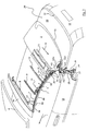
Dieser umfaßt den beiden Fahrzeugseiten jeweils zugeordnete seitliche Rahmenteile
4, 5, die im geschlossenen Zustand des Daches fluchtend hintereinander liegen.
Dabei erstreckt sich das erste Rahmenteil 4 von einem Windschutzscheibenrahmen
6 oder einem festen vorderen Querende 36 des Daches bis zu einer zwischen
den Rahmenteilen 4, 5 liegenden Trennfuge 7. Das hintere Rahmenteil erstreckt
sich von der Trennfuge 7 bis zum hinteren Dachteil 2. Auch eine andere Anzahl
von seitlichen Rahmenteilen ist möglich. Die Rahmenteile sind durch Querspriegel
9, 10, 11 miteinander verbunden. Über diese ist ein insgesamt mit 12 bezeichneter
Dachbezug gespannt. Der hintere Spriegel 11 ist im geschlossenen Zustand
unmittelbar vor dem hinteren Dachteil 2 gehalten und bildet eine Art Spannleiste
für den rückseitigen Abschluß 13 des Dachbezugs 12. Zudem ist ein vorderes
Synchronisationsgestänge 8 vorgesehen, das wie die Spriegel 9, 10, 11 den Dachbezug
12 quer unterläuft. Damit kann bei der unten beschriebenen Dachverkürzung
eine gleichmäßige Bewegung der beiden Dachseiten parallel zur Fahrzeuglängsrichtung
erreicht werden.This includes side frame parts assigned to the two sides of the
Im Bereich des hinteren Spriegels 11 ist an jeder Fahrzeugseite je ein Antriebsorgan
14 - hier als Hydraulikzylinder ausgebildet- angeordnet, der sich von dem Spriegel
11 bis zu einem Gelenk 15 erstreckt, das im Bereich der Trennfuge 7 angeordnet ist
und um zumindest eine vertikale Achse 16 aufschwenkbar ist. Das Antriebsorgan 14
ist von dem Bezug 12 überdeckt. Sein vorderes Ende ist weiter in Richtung einer
vertikalen Fahrzeuglängsmittelebene verlagert als sein rückwärtiges Ende. Das Gelenk
15 ist mit den seitlichen Rahmenteilen 4, 5 im Nahbereich der Teilungsfuge 7
verbunden. Das vordere Rahmenteil 4 ist im Verlauf seiner Längserstreckung in einem
von der Trennfuge 7 entfernten Bereich an dem Gelenk 17 geteilt in den bezüglich
einer vertikalen Fahrzeuglängsebene nicht schwenkbaren vorderen Abschnitt
4a und den demgegenüber um eine vertikale Achse 18 des Gelenks 17 in
Richtung der vertikalen Fahrzeuglängsmittelebene 19 einschwenkbaren Abschnitt
4b. Das hintere Rahmenteil 5 ist im Verlauf seiner Längserstreckung ebenfalls in
einem von der Trennfuge 7 entfernten Bereich an dem Gelenk 20 geteilt in den bezüglich
einer vertikalen Fahrzeuglängsebene nicht schwenkbaren hinteren Abschnitt
5a und einen demgegenüber um eine vertikale Achse 21 des Gelenks 20 in Richtung
der vertikalen Fahrzeuglängsmittelebene 19 einschwenkbaren Abschnitt 5b.In the area of the
Das hintere Dachteil 2 und das flexible Dachteil 3 bilden in jeder Phase ihrer Bewegung
eine zusammenhängende Dachaußenfläche aus, die nicht - etwa im Bereich
des Übergangs vom Dachteil 2 zum Dachbereich 3 - durch eine offene Fuge unterbrochen
ist. Dabei kann der textile Bezug 12 entweder an dem festen Dachteil 2 angehängt
sein oder diesen mit übergreifen.The
Hier ist eine Ausführung dargestellt, in der das hintere Dachteil 2 insgesamt als
Glas- oder Kunststoffkuppel ausgebildet ist und an seiner vorderen Kante 22 mit
dem Bezug 12 verbunden ist, ohne von diesem übergriffen zu sein. Um die Innenraumaufheizung
zu vermindern, kann das kuppelartige hintere Dachteil dabei außerhalb
eines mittleren Durchsichtsbereich mit einer dunklen, licht- und/oder wärmeabsorbierenden
Beschichtung versehen sein.Here, an embodiment is shown in which the
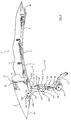
Das hintere Dachteil 2 ist über ein insgesamt mit 23 bezeichnetes Gestänge an jeder
Fahrzeugseite mit einem Hauptlager 24 verbunden, um das herum das hintere
Dachteil 2 um eine in Fahrzeugquerrichtung weisende Horizontalachse aufgeschwenkt
werden kann. Das Gestänge 23 umfaßt zwei Antriebsorgane 25, 26. Das
Antriebsorgan 25 ist kolbenstangenseitig über einen Hebel Gh mit einem Gelenkparallelogramm
G verbunden. Dieses umfaßt die vier Teile G1, G2, G3 und G4, die
an den Schwenkgelenken GS1, GS2, GS3 und GS4 miteinander verbunden sind.
Die Schwenkachsen dieser Gelenke verlaufen horizontal und in Fahrzeugquerrichtung.
Mit den Gelenken GS3 und GS4 greift das Viergelenk G am rückwärtigen Ende
des vorderen Dachteils an, wodurch mit der Betätigung dieses Viergelenks G
eine Relativbewegung zwischen den Dachteilen 2 und 3 bewirkbar ist.The
Das Antriebsorgan 26 greift hingegen kolbenstangenseitig an einem ersten Lenker
H1 des zweiten Gelenkparallelogramms H an. Der Lenker H1 erstreckt sich darin
parallel zum Lenker H3. Dazwischen liegen die Lenker H2 und H4, über die Gelenke
HS1 bzw. HS 2 mit dem Lenker H1 und über die Gelenke HS 3 bzw. HS 4 mit dem
Lenker H3 verbunden sind. Im Ausführungsbeispiel sind die Antriebsorgane 25, 26
derart angeordnet, daß mit deren Hilfe eine nahezu vertikale Hubbewegung des
Dachteils 2 vermittelbar ist. Die Relativbewegung des vorderen Dachteils 3 kann in
einer unbeweglichen Stellung des hinteren Dachteils 2 stattfinden.The
Zudem ist noch ein drittes Antriebsorgan 27 vorgesehen, das an einem Haupthebel
28 angreift und dadurch eine Schwenkbewegung mit einem großen Schwenkwinkel
um das Hauptlager 24 bewirken kann.In addition, a
In geschlossener Stellung des Daches liegt das hintere Dachteil 2 mit seiner rückwärtigen
Kante 35 auf einem Deckelteil 29 auf. Dieser dient in Doppelfunktion sowohl
zum Abdecken des Verdeckkastens als auch des Kofferraums. Entsprechend
kann das Deckelteil 29 in einem ersten Sinne zur Freigabe einer Durchtrittsöffnung
für das Dach und in einem zweiten Sinne zur Freigabe einer Beladeöffnung für den
Kofferraum geöffnet werden. Das Deckelteil ist hierfür zweiteilig ausgebildet, wobei
der vordere Teil 30 an einer Querfuge 31 an den hinteren Teil 32 anschließt. Der
vordere Teil 30 ist mit seinem in Fahrtrichtung F vorderen Ende in einer Längsführungskulisse
beweglich gehalten und im Bereich der Querfuge 31 mit dem hinteren
Teil 32 schwenkbar verbunden. Der hintere Teil 32 ist an seiner rückwärtigen Kante
schwenkbar an der Fahrzeugkarosserie 33 angelenkt. Die Schwenkbewegung des
hinteren Teils 32 des Deckelteils 29 ist durch zumindest ein im Bereich der rückwärtigen
Anlenkung des hinteren Teils 32 gelegenen Antriebsorgan bewirkbar.In the closed position of the roof, the
Um das Dach aus seiner geschlossenen Stellung gemäß den Figuren 1 und 2 in die Offenstellung nach den Figuren 15 und 16 zu überführen, findet der folgende Ablauf statt:To the roof from its closed position according to Figures 1 and 2 in the The following procedure takes place to transfer the open position according to FIGS. 15 and 16 instead of:
In einem ersten Schritt (Figuren 3 und 4) wird das hintere Dachteil 2 angehoben.
Dieses Anheben kann als rein vertikale Hubbewegung stattfinden. Hierfür wird das
hintere Antriebsorgan 26 ausgefahren. Dadurch, daß die Gelenke HS2 und HS3
zunächst durch den unbewegten Haupthebel 28 in einer karosseriefesten Position
gehalten sind, wird durch das Antriebsorgan 26 das Viergelenk H derart geöffnet,
das die Lenker H1 und H3 um die genannten Gelenke HS2 und HS3 aufschwenken,
so daß die hinteren Gelenke HS1 und HS4, die an dem hinteren Dachteil 2 gehalten
sind, vorwärts und aufwärts verschwenken. Das hintere Dachteil hebt dadurch um
einige Zentimeter vom Deckelteil 29 ab. Das Abheben ist durch das Gelenkparallelogramm
als Kombinationsbewegung aus Hub- und Schwenkbewegung ausgebildet.
Das Dachteil 2 wird dabei in geringem Maß über den flexiblen Dachbereich 3 geschoben,
wodurch dessen Bezug 12 entspannen kann.In a first step (Figures 3 and 4), the
In dieser Stellung des hinteren Dachteils 2 kann der Verdeckkastendeckel 29 geöffnet
werden. Hierfür wird dessen heckseitiges Teil 32 durch das oder die zugeordneten
Antriebsorgane - nicht dargestellt - gegenüber der Karosserie 33 aufgeschwenkt.
Durch die Kopplung des Teils 32 mit einem vorderen Teil 30 des Verdeckkastendeckels
29 wird dieses mit entgegen der Fahrtrichtung F gezogen. Dabei
ist das vordere Ende des vorderen Teils 30 in einer Längsführungskulisse gehalten. In this position of the
Die Zugbewegung auf das vordere Teil 31 bewirkt daher gleichzeitig ein Anheben
seiner vorderen Kante. Seine hintere Kante wird durch das Aufschwenken des hinteren
Teils 32 deutlicher angehoben und gleichzeitig heckwärts unter dem hinteren
Dachteil 2 weggezogen. In Anpassung hieran ist in dieser Bewegungsphase der
umlaufende rückwärtige Rand 35 des hinteren Dachteils 2 leicht heckwärts aufwärts
gestellt. Insgesamt muß zum Ermöglichen der Verdeckkastendeckelöffnung das
hintere Dachteil 2 nur um ein geringes Maß angehoben werden. Die Gesamtbewegung
ist dadurch beschleunigt.The pulling movement on the
Zur weiteren Öffnung wird das Dach zunächst durch Betätigung des Antriebsorgans
27 über den Haupthebel 28 ein Stück weit heckwärts verschwenkt (Figuren 5 und 6),
wodurch die Kopffreiheit für die Insassen vergrößert wird. Gleichzeitig wird der gesamte
flexible Dachbereich 3 im noch nicht verkürzten Zustand durch Betätigung
des Antriebsorgans 25 heckwärts in Richtung unter das hintere Dachteil 2 verlagert.To open it further, the roof is opened by actuating the
Aus dieser Position heraus beginnt die Einfaltbewegung des flexiblen Dachbereichs
3 (Figuren 7 bis 10). Dabei können die Antriebsorgane 25, 26 und 27 in konstanter
Stellung verbleiben. Das im wesentlichen horizontal liegende Antriebsorgan 14 wird
angezogen, wodurch das Gelenk 15, das im Ausführungsbeispiel als horizontal liegendes
und um eine vertikale Achse schwenkbares Gelenk nach Art eines als Scherengitter
ausgebildeten Siebengelenks ausgebildet ist, geöffnet wird. Dieses ist mit
dem vorderen seitlichen Rahmenteil 4 sowie mit dem rückwärtigen Rahmenteil 5
jeweils im Nahbereich der Trennfuge 7 verbunden und übt auf diese ein Drehmoment
aus. Dieses zieht die Abschnitte 4b und 5b in Richtung der vertikalen Fahrzeuglängsmittelebene
19 einwärts. Der Abschnitt 4b schwenkt dabei gegenüber
dem vorderen, seine Längsorientierung beibehaltendem Abschnitt 4a um die vertikale
Achse 18 des Gelenks 17 ein; der Abschnitt 5b des hinteren Rahmenteils 5
schwenkt dabei gegenüber seinem hinteren, seine Längsorientierung beibehaltendem
Abschnitt 5a um die vertikale Achse 21 des Gelenks 20 ein.The fold-in movement of the flexible roof area begins from this position
3 (Figures 7 to 10). The
Bei der Verkürzung des flexiblen Dachbereichs 3 lösen sich die Spriegel 10,11 von
dem Dachbezug 12, so daß dieser gegenüber den ihn untergreifenden Teilen beweglich
wird. Es können Zugbänder oder dergleichen Mittel - nicht dargestellt - vorgesehen
sein, um eine Zwangseinfaltung des Bezuges 12 zu gewährleisten, wodurch
dieser die beispielsweise in den Fig. 10 und 12 dargestellte Faltungsstruktur
erreicht und während der Verkürzung des flexiblen Dachbereichs 3 sich in definierter
Weise ohne Ausbildung von scharfen Knicken einfaltet.When the
Die Abschnitte 4b, 5b werden durch das Antriebsorgan 14 derart weit um die Gelenke
17 bzw. 20 eingeschwenkt, daß sie am Ende der Dachverkürzung (Fig. 11, Fig.
12) sich im wesentlichen vollständig in Fahrzeugquerrichtung erstrecken. Die Teilungsfuge
7 liegt dann nahe der vertikalen Fahrzeuglängsmittelebene 19. Das Antriebsorgan
14 ist ebenfalls in eine quer zur Fahrtrichtung F weisende Stellung verschwenkt
worden. Während der Verkürzung des flexiblen Dachbereichs 3 wird
gleichzeitig durch Öffnen des Viergelenks G über das Antriebsorgan 25, das an dem
Hebel Gh angreift und dadurch die Hebel G2 und G4 um die Gelenke GS1 und GS2
in eine im wesentlichen horizontale Position bringt, das rückwärtige Ende des flexiblen
Dachbereichs 3 nach hinten gezogen, wodurch der hintere Spriegel 11 etwa in
den Bereich der rückwärtigen Kante 35 des starren hinteren Dachteils 2 gelangt.
Durch die Loslösung des Dachbezugs 12 kann dessen rückwärtiges Ende an der
vorderen Kante des hinteren Dachteils 2 befestigt bleiben, ohne unter Spannung zu
geraten (sh. Fig. 12).The
Wie in Fig. 12 deutlich wird, ist die Längserstreckung des so gebildeten Pakets außerordentlich
gering und ist im wesentlichen bestimmt durch das Längsausmaß des
hinteren starren Dachteils 2. Der Dachbezug kann in seinen einzelnen Bereichen
eng aufeinander liegen, ohne daß Spriegel oder dergleichen die Mindesthöhe des
entstehenden Pakets begrenzen würden. Durch Absenkung des starren Dachteils 2
wird in dieser Phase der Bewegung die Höhe des anschließend abzulegenden Daches
vermindert, es bildet sich ein flaches Paket.As is clear in Fig. 12, the length of the package thus formed is extraordinary
low and is essentially determined by the length of the
rear
Das so entstandene Paket, das oberseitig von dem starren Dachteil 2 begrenzt ist,
wird durch Ausfahren des Antriebsorgans 27 und damit verbundenes Aufschwenken
des Haupthebels 28 in eine nahezu horizontale Stellung (Fig. 13 bis 16) rückwärtig
verschwenkt und dabei unterhalb der Fensterbrüstungslinie derart abgelegt, daß
auch in geschlossener Stellung das starre rückwärtige Dachteil das abgelegte Dach
nach oben hin begrenzt. Gleichzeitig wird das Antriebsorgan 25, das direkt auf das
Mehrgelenk G einwirkt, ein Stück weit eingefahren.The resulting package, which is delimited on the top by the
Insgesamt ist somit ein sehr kurzes und gleichzeitig in der Höhe minimiertes Paket entstanden, wodurch das abgelegte Dach im Kofferraum nur wenig Platz beansprucht und dieser nur geringfügig eingeschränkt ist.Overall, this is a very short package that is also minimized in height originated, whereby the stored roof in the trunk takes up little space and this is only slightly restricted.
Es versteht sich, daß die einzelnen Bewegungsphasen ohne Unterbrechungen unmittelbar hintereinander ablaufen und auch überlappen können, wodurch sich eine besonders schnelle Dachbewegung ergibt.It is understood that the individual phases of movement without interruptions immediately run in succession and can also overlap, which results in a results in particularly rapid roof movement.
Claims (4)
Applications Claiming Priority (2)
| Application Number | Priority Date | Filing Date | Title |
|---|---|---|---|
| DE10140232A DE10140232A1 (en) | 2001-08-22 | 2001-08-22 | Cabriolet vehicle with a rigid rear roof section |
| DE10140232 | 2001-08-22 |
Publications (3)
| Publication Number | Publication Date |
|---|---|
| EP1285801A2 true EP1285801A2 (en) | 2003-02-26 |
| EP1285801A3 EP1285801A3 (en) | 2003-05-07 |
| EP1285801B1 EP1285801B1 (en) | 2007-03-07 |
Family
ID=7695652
Family Applications (1)
| Application Number | Title | Priority Date | Filing Date |
|---|---|---|---|
| EP02017988A Expired - Lifetime EP1285801B1 (en) | 2001-08-22 | 2002-08-12 | Convertible vehicle with a rigid rear roof element |
Country Status (3)
| Country | Link |
|---|---|
| EP (1) | EP1285801B1 (en) |
| AT (1) | ATE355988T1 (en) |
| DE (2) | DE10140232A1 (en) |
Cited By (6)
| Publication number | Priority date | Publication date | Assignee | Title |
|---|---|---|---|---|
| US6666494B2 (en) * | 2001-12-07 | 2003-12-23 | Webasto Vehicle Systems International Gmbh | Folding convertible top for a motor vehicle |
| DE102004024235A1 (en) * | 2004-05-15 | 2005-12-15 | Wilhelm Karmann Gmbh | Folding roof deck for convertible vehicles, has two hydraulic cylinders, one of which supporting rear roof segment or its articulated connection with respect to main chamber, while other is interlocked with four point linkage |
| DE10357099B4 (en) * | 2003-12-06 | 2006-03-16 | Wilhelm Karmann Gmbh | Convertible car |
| DE102005061201B3 (en) * | 2005-12-19 | 2007-04-05 | Rausch & Pausch Gmbh | Convertible system for e.g. cabriolet-vehicle, has support for lever and provided in guiding part, where lever is connected with rear roof part, and connecting strap between guiding body and lever is hinged to lever |
| DE102006004108A1 (en) * | 2006-01-28 | 2007-08-02 | Wilhelm Karmann Gmbh | Roof kinematics for a vehicle roof to be opened |
| EP1736337A3 (en) * | 2005-06-22 | 2009-03-25 | Wilhelm Karmann GmbH | Convertible vehicle with at least one side frame component which is moveable inwards when the vehicle roof is opened |
Families Citing this family (6)
| Publication number | Priority date | Publication date | Assignee | Title |
|---|---|---|---|---|
| DE10242501B4 (en) * | 2002-09-12 | 2007-09-13 | Magna Car Top Systems Gmbh | Vehicle roof for a convertible vehicle |
| DE10248344A1 (en) * | 2002-10-17 | 2004-05-06 | Wilhelm Karmann Gmbh | motor vehicle |
| DE10337474A1 (en) * | 2003-08-14 | 2005-06-02 | Wilhelm Karmann Gmbh | Convertible car |
| DE102004047872A1 (en) | 2004-03-29 | 2005-10-20 | Karmann Gmbh W | Convertible car |
| DE102004051851A1 (en) * | 2004-10-26 | 2006-04-27 | Wilhelm Karmann Gmbh | Cabriolet soft top system for Cabriolet vehicles has linkage portions whose angle may be varied to vary translatory movement of roof portion |
| DE102008030202A1 (en) | 2008-06-25 | 2009-12-31 | Wilhelm Karmann Gmbh | Cabriolet-vehicle, has rear roof section moved in vehicle vertical direction when hood is closed such that extended opening is formed by section's vertical movement and rear flap's opening movement during closing of hood |
Family Cites Families (6)
| Publication number | Priority date | Publication date | Assignee | Title |
|---|---|---|---|---|
| DE1179125B (en) * | 1960-12-24 | 1964-10-01 | Karosseriewerk Porsche G M B H | Convertible top with a rear window with a frame |
| IT1281353B1 (en) * | 1995-09-22 | 1998-02-18 | Pininfarina Spa | CONVERTIBLE CAR WITH RIGID AND COLLAPSIBLE ROOF ROOF |
| DE19639567C2 (en) * | 1996-09-26 | 1998-11-26 | Daimler Benz Ag | Roof construction for an open passenger car |
| DE19704570C2 (en) * | 1997-02-07 | 2003-03-06 | Daimler Chrysler Ag | Car with an openable roof |
| DE19846006B4 (en) * | 1998-10-06 | 2006-05-24 | Edscha Cabrio-Dachsysteme Gmbh | Rigid folding roof for motor vehicles |
| EP1092579B1 (en) * | 1999-10-12 | 2002-06-26 | Dura Convertible Systems GmbH | Retractable folding top for motor vehicle and vehicle provided with this folding top |
-
2001
- 2001-08-22 DE DE10140232A patent/DE10140232A1/en not_active Withdrawn
-
2002
- 2002-08-12 EP EP02017988A patent/EP1285801B1/en not_active Expired - Lifetime
- 2002-08-12 DE DE50209635T patent/DE50209635D1/en not_active Expired - Lifetime
- 2002-08-12 AT AT02017988T patent/ATE355988T1/en not_active IP Right Cessation
Non-Patent Citations (1)
| Title |
|---|
| None |
Cited By (7)
| Publication number | Priority date | Publication date | Assignee | Title |
|---|---|---|---|---|
| US6666494B2 (en) * | 2001-12-07 | 2003-12-23 | Webasto Vehicle Systems International Gmbh | Folding convertible top for a motor vehicle |
| DE10357099B4 (en) * | 2003-12-06 | 2006-03-16 | Wilhelm Karmann Gmbh | Convertible car |
| DE102004024235A1 (en) * | 2004-05-15 | 2005-12-15 | Wilhelm Karmann Gmbh | Folding roof deck for convertible vehicles, has two hydraulic cylinders, one of which supporting rear roof segment or its articulated connection with respect to main chamber, while other is interlocked with four point linkage |
| DE102004024235B4 (en) * | 2004-05-15 | 2007-04-19 | Wilhelm Karmann Gmbh | Hood for a convertible vehicle |
| EP1736337A3 (en) * | 2005-06-22 | 2009-03-25 | Wilhelm Karmann GmbH | Convertible vehicle with at least one side frame component which is moveable inwards when the vehicle roof is opened |
| DE102005061201B3 (en) * | 2005-12-19 | 2007-04-05 | Rausch & Pausch Gmbh | Convertible system for e.g. cabriolet-vehicle, has support for lever and provided in guiding part, where lever is connected with rear roof part, and connecting strap between guiding body and lever is hinged to lever |
| DE102006004108A1 (en) * | 2006-01-28 | 2007-08-02 | Wilhelm Karmann Gmbh | Roof kinematics for a vehicle roof to be opened |
Also Published As
| Publication number | Publication date |
|---|---|
| EP1285801A3 (en) | 2003-05-07 |
| DE50209635D1 (en) | 2007-04-19 |
| ATE355988T1 (en) | 2007-03-15 |
| EP1285801B1 (en) | 2007-03-07 |
| DE10140232A1 (en) | 2003-03-13 |
Similar Documents
| Publication | Publication Date | Title |
|---|---|---|
| EP1285799B1 (en) | Convertible vehicle with an at least locally flexible roof | |
| DE10050286B4 (en) | Multi-part cover for vehicles | |
| EP1074415A2 (en) | Convertible vehicle | |
| EP1284209B1 (en) | Convertible vehicle | |
| EP1565335B1 (en) | Motor vehicle | |
| EP1900562B1 (en) | Convertible vehicle with a roof composed of several parts | |
| EP1831043B1 (en) | Cabriolet vehicle having a movable rear-window shelf | |
| EP1735171B1 (en) | Rod kinematics for a hardtop of a vehicle | |
| EP1285801A2 (en) | Convertible vehicle with a rigid rear roof element | |
| DE10217917A1 (en) | Cabriolet vehicle with at least two rigid roof parts | |
| DE10248344A1 (en) | motor vehicle | |
| EP1331121B1 (en) | Adjustment device for a foldable roof of a vehicle | |
| DE10309366B4 (en) | Convertible car | |
| EP1897718B1 (en) | Folding soft top | |
| EP1588881B1 (en) | Vehicle with movable roof parts | |
| DE102017102598A1 (en) | Hood of a convertible vehicle with surface mirrors | |
| EP2004432B1 (en) | Hardtop folding roof for an open motor vehicle | |
| DE10248346B3 (en) | motor vehicle | |
| EP1656273B1 (en) | Convertible | |
| WO2005120875A1 (en) | Convertible vehicle | |
| DE102007054469B4 (en) | vehicle top | |
| EP2036753B1 (en) | Collapsible roof fitting for a convertible | |
| EP1679215B1 (en) | Rearward boot lid attachment for a cabriolet vehicle | |
| DE10254365A1 (en) | motor vehicle | |
| WO2004062951A1 (en) | Cabriolet vehicle |
Legal Events
| Date | Code | Title | Description |
|---|---|---|---|
| PUAI | Public reference made under article 153(3) epc to a published international application that has entered the european phase |
Free format text: ORIGINAL CODE: 0009012 |
|
| AK | Designated contracting states |
Kind code of ref document: A2 Designated state(s): AT BE BG CH CY CZ DE DK EE ES FI FR GB GR IE IT LI LU MC NL PT SE SK TR |
|
| AX | Request for extension of the european patent |
Extension state: AL LT LV MK RO SI |
|
| PUAL | Search report despatched |
Free format text: ORIGINAL CODE: 0009013 |
|
| AK | Designated contracting states |
Designated state(s): AT BE BG CH CY CZ DE DK EE ES FI FR GB GR IE IT LI LU MC NL PT SE SK TR |
|
| AX | Request for extension of the european patent |
Extension state: AL LT LV MK RO SI |
|
| RIC1 | Information provided on ipc code assigned before grant |
Ipc: 7B 60J 7/12 A Ipc: 7B 60J 1/18 B |
|
| 17P | Request for examination filed |
Effective date: 20030528 |
|
| AKX | Designation fees paid |
Designated state(s): AT BE BG CH CY CZ DE DK EE ES FI FR GB GR IE IT LI LU MC NL PT SE SK TR |
|
| GRAP | Despatch of communication of intention to grant a patent |
Free format text: ORIGINAL CODE: EPIDOSNIGR1 |
|
| GRAS | Grant fee paid |
Free format text: ORIGINAL CODE: EPIDOSNIGR3 |
|
| GRAA | (expected) grant |
Free format text: ORIGINAL CODE: 0009210 |
|
| AK | Designated contracting states |
Kind code of ref document: B1 Designated state(s): AT BE BG CH CY CZ DE DK EE ES FI FR GB GR IE IT LI LU MC NL PT SE SK TR |
|
| PG25 | Lapsed in a contracting state [announced via postgrant information from national office to epo] |
Ref country code: FI Free format text: LAPSE BECAUSE OF FAILURE TO SUBMIT A TRANSLATION OF THE DESCRIPTION OR TO PAY THE FEE WITHIN THE PRESCRIBED TIME-LIMIT Effective date: 20070307 Ref country code: NL Free format text: LAPSE BECAUSE OF FAILURE TO SUBMIT A TRANSLATION OF THE DESCRIPTION OR TO PAY THE FEE WITHIN THE PRESCRIBED TIME-LIMIT Effective date: 20070307 Ref country code: IE Free format text: LAPSE BECAUSE OF FAILURE TO SUBMIT A TRANSLATION OF THE DESCRIPTION OR TO PAY THE FEE WITHIN THE PRESCRIBED TIME-LIMIT Effective date: 20070307 |
|
| REG | Reference to a national code |
Ref country code: GB Ref legal event code: FG4D Free format text: NOT ENGLISH |
|
| REG | Reference to a national code |
Ref country code: CH Ref legal event code: EP |
|
| REF | Corresponds to: |
Ref document number: 50209635 Country of ref document: DE Date of ref document: 20070419 Kind code of ref document: P |
|
| REG | Reference to a national code |
Ref country code: IE Ref legal event code: FG4D Free format text: LANGUAGE OF EP DOCUMENT: GERMAN |
|
| PG25 | Lapsed in a contracting state [announced via postgrant information from national office to epo] |
Ref country code: SE Free format text: LAPSE BECAUSE OF FAILURE TO SUBMIT A TRANSLATION OF THE DESCRIPTION OR TO PAY THE FEE WITHIN THE PRESCRIBED TIME-LIMIT Effective date: 20070607 |
|
| GBT | Gb: translation of ep patent filed (gb section 77(6)(a)/1977) |
Effective date: 20070523 |
|
| PG25 | Lapsed in a contracting state [announced via postgrant information from national office to epo] |
Ref country code: ES Free format text: LAPSE BECAUSE OF FAILURE TO SUBMIT A TRANSLATION OF THE DESCRIPTION OR TO PAY THE FEE WITHIN THE PRESCRIBED TIME-LIMIT Effective date: 20070618 |
|
| PG25 | Lapsed in a contracting state [announced via postgrant information from national office to epo] |
Ref country code: PT Free format text: LAPSE BECAUSE OF FAILURE TO SUBMIT A TRANSLATION OF THE DESCRIPTION OR TO PAY THE FEE WITHIN THE PRESCRIBED TIME-LIMIT Effective date: 20070807 |
|
| NLV1 | Nl: lapsed or annulled due to failure to fulfill the requirements of art. 29p and 29m of the patents act | ||
| REG | Reference to a national code |
Ref country code: IE Ref legal event code: FD4D |
|
| PG25 | Lapsed in a contracting state [announced via postgrant information from national office to epo] |
Ref country code: SK Free format text: LAPSE BECAUSE OF FAILURE TO SUBMIT A TRANSLATION OF THE DESCRIPTION OR TO PAY THE FEE WITHIN THE PRESCRIBED TIME-LIMIT Effective date: 20070307 |
|
| PG25 | Lapsed in a contracting state [announced via postgrant information from national office to epo] |
Ref country code: CZ Free format text: LAPSE BECAUSE OF FAILURE TO SUBMIT A TRANSLATION OF THE DESCRIPTION OR TO PAY THE FEE WITHIN THE PRESCRIBED TIME-LIMIT Effective date: 20070307 |
|
| PLBE | No opposition filed within time limit |
Free format text: ORIGINAL CODE: 0009261 |
|
| STAA | Information on the status of an ep patent application or granted ep patent |
Free format text: STATUS: NO OPPOSITION FILED WITHIN TIME LIMIT |
|
| PG25 | Lapsed in a contracting state [announced via postgrant information from national office to epo] |
Ref country code: DK Free format text: LAPSE BECAUSE OF FAILURE TO SUBMIT A TRANSLATION OF THE DESCRIPTION OR TO PAY THE FEE WITHIN THE PRESCRIBED TIME-LIMIT Effective date: 20070307 |
|
| 26N | No opposition filed |
Effective date: 20071210 |
|
| BERE | Be: lapsed |
Owner name: WILHELM KARMANN G.M.B.H. Effective date: 20070831 |
|
| REG | Reference to a national code |
Ref country code: CH Ref legal event code: PL |
|
| PG25 | Lapsed in a contracting state [announced via postgrant information from national office to epo] |
Ref country code: CH Free format text: LAPSE BECAUSE OF NON-PAYMENT OF DUE FEES Effective date: 20070831 Ref country code: LI Free format text: LAPSE BECAUSE OF NON-PAYMENT OF DUE FEES Effective date: 20070831 Ref country code: GR Free format text: LAPSE BECAUSE OF FAILURE TO SUBMIT A TRANSLATION OF THE DESCRIPTION OR TO PAY THE FEE WITHIN THE PRESCRIBED TIME-LIMIT Effective date: 20070608 Ref country code: MC Free format text: LAPSE BECAUSE OF NON-PAYMENT OF DUE FEES Effective date: 20070831 |
|
| PG25 | Lapsed in a contracting state [announced via postgrant information from national office to epo] |
Ref country code: BE Free format text: LAPSE BECAUSE OF NON-PAYMENT OF DUE FEES Effective date: 20070831 |
|
| PG25 | Lapsed in a contracting state [announced via postgrant information from national office to epo] |
Ref country code: AT Free format text: LAPSE BECAUSE OF NON-PAYMENT OF DUE FEES Effective date: 20070812 |
|
| PG25 | Lapsed in a contracting state [announced via postgrant information from national office to epo] |
Ref country code: EE Free format text: LAPSE BECAUSE OF FAILURE TO SUBMIT A TRANSLATION OF THE DESCRIPTION OR TO PAY THE FEE WITHIN THE PRESCRIBED TIME-LIMIT Effective date: 20070307 |
|
| PG25 | Lapsed in a contracting state [announced via postgrant information from national office to epo] |
Ref country code: CY Free format text: LAPSE BECAUSE OF FAILURE TO SUBMIT A TRANSLATION OF THE DESCRIPTION OR TO PAY THE FEE WITHIN THE PRESCRIBED TIME-LIMIT Effective date: 20070307 |
|
| PG25 | Lapsed in a contracting state [announced via postgrant information from national office to epo] |
Ref country code: BG Free format text: LAPSE BECAUSE OF FAILURE TO SUBMIT A TRANSLATION OF THE DESCRIPTION OR TO PAY THE FEE WITHIN THE PRESCRIBED TIME-LIMIT Effective date: 20070607 Ref country code: LU Free format text: LAPSE BECAUSE OF NON-PAYMENT OF DUE FEES Effective date: 20070812 |
|
| PG25 | Lapsed in a contracting state [announced via postgrant information from national office to epo] |
Ref country code: TR Free format text: LAPSE BECAUSE OF FAILURE TO SUBMIT A TRANSLATION OF THE DESCRIPTION OR TO PAY THE FEE WITHIN THE PRESCRIBED TIME-LIMIT Effective date: 20070307 |
|
| PGFP | Annual fee paid to national office [announced via postgrant information from national office to epo] |
Ref country code: IT Payment date: 20100818 Year of fee payment: 9 |
|
| PG25 | Lapsed in a contracting state [announced via postgrant information from national office to epo] |
Ref country code: IT Free format text: LAPSE BECAUSE OF NON-PAYMENT OF DUE FEES Effective date: 20110812 |
|
| PGFP | Annual fee paid to national office [announced via postgrant information from national office to epo] |
Ref country code: FR Payment date: 20130820 Year of fee payment: 12 Ref country code: GB Payment date: 20130823 Year of fee payment: 12 |
|
| REG | Reference to a national code |
Ref country code: GB Ref legal event code: 732E Free format text: REGISTERED BETWEEN 20131114 AND 20131120 |
|
| REG | Reference to a national code |
Ref country code: FR Ref legal event code: TP Owner name: VALMET AUTOMOTIVE OY, FI Effective date: 20131209 |
|
| REG | Reference to a national code |
Ref country code: DE Ref legal event code: R081 Ref document number: 50209635 Country of ref document: DE Owner name: VALMET AUTOMOTIVE OY, FI Free format text: FORMER OWNER: WILHELM KARMANN GMBH, 49084 OSNABRUECK, DE Effective date: 20131128 Ref country code: DE Ref legal event code: R082 Ref document number: 50209635 Country of ref document: DE Representative=s name: KRONTHALER, SCHMIDT & COLL. PATENTANWALTSKANZL, DE Effective date: 20131128 |
|
| PGFP | Annual fee paid to national office [announced via postgrant information from national office to epo] |
Ref country code: DE Payment date: 20140922 Year of fee payment: 13 |
|
| GBPC | Gb: european patent ceased through non-payment of renewal fee |
Effective date: 20140812 |
|
| REG | Reference to a national code |
Ref country code: FR Ref legal event code: ST Effective date: 20150430 |
|
| PG25 | Lapsed in a contracting state [announced via postgrant information from national office to epo] |
Ref country code: GB Free format text: LAPSE BECAUSE OF NON-PAYMENT OF DUE FEES Effective date: 20140812 |
|
| PG25 | Lapsed in a contracting state [announced via postgrant information from national office to epo] |
Ref country code: FR Free format text: LAPSE BECAUSE OF NON-PAYMENT OF DUE FEES Effective date: 20140901 |
|
| REG | Reference to a national code |
Ref country code: DE Ref legal event code: R119 Ref document number: 50209635 Country of ref document: DE |
|
| PG25 | Lapsed in a contracting state [announced via postgrant information from national office to epo] |
Ref country code: DE Free format text: LAPSE BECAUSE OF NON-PAYMENT OF DUE FEES Effective date: 20160301 |