EP1285790B1 - In-car sensor with intake fan motor - Google Patents
In-car sensor with intake fan motor Download PDFInfo
- Publication number
- EP1285790B1 EP1285790B1 EP02701710A EP02701710A EP1285790B1 EP 1285790 B1 EP1285790 B1 EP 1285790B1 EP 02701710 A EP02701710 A EP 02701710A EP 02701710 A EP02701710 A EP 02701710A EP 1285790 B1 EP1285790 B1 EP 1285790B1
- Authority
- EP
- European Patent Office
- Prior art keywords
- humidity
- sensor
- fan motor
- temperature
- motor
- Prior art date
- Legal status (The legal status is an assumption and is not a legal conclusion. Google has not performed a legal analysis and makes no representation as to the accuracy of the status listed.)
- Expired - Lifetime
Links
Images


Classifications
-
- B—PERFORMING OPERATIONS; TRANSPORTING
- B60—VEHICLES IN GENERAL
- B60H—ARRANGEMENTS OF HEATING, COOLING, VENTILATING OR OTHER AIR-TREATING DEVICES SPECIALLY ADAPTED FOR PASSENGER OR GOODS SPACES OF VEHICLES
- B60H1/00—Heating, cooling or ventilating devices
- B60H1/00642—Control systems or circuits; Control members or indication devices for heating, cooling or ventilating devices
- B60H1/00735—Control systems or circuits characterised by their input, i.e. by the detection, measurement or calculation of particular conditions, e.g. signal treatment, dynamic models
- B60H1/00792—Arrangement of detectors
-
- F—MECHANICAL ENGINEERING; LIGHTING; HEATING; WEAPONS; BLASTING
- F04—POSITIVE - DISPLACEMENT MACHINES FOR LIQUIDS; PUMPS FOR LIQUIDS OR ELASTIC FLUIDS
- F04D—NON-POSITIVE-DISPLACEMENT PUMPS
- F04D25/00—Pumping installations or systems
- F04D25/02—Units comprising pumps and their driving means
- F04D25/06—Units comprising pumps and their driving means the pump being electrically driven
- F04D25/0606—Units comprising pumps and their driving means the pump being electrically driven the electric motor being specially adapted for integration in the pump
- F04D25/0666—Units comprising pumps and their driving means the pump being electrically driven the electric motor being specially adapted for integration in the pump a sensor is integrated into the pump/motor design
Definitions
- This invention relates to a sensor according to the preamble of claim 1.
- some automotive air conditioners sample air temperature at a predetermined position within a vehicle cabin, and perform air conditioning such that the temperature within the vehicle cabin becomes equal to a preset temperature.
- a sensor equipped with an aspirator fan motor is known from US-5731953 A, comprising a thermistor as a temperature-sensing element and a motor-driven aspirator fan for forcibly drawing air from an inlet port to the thermistor and from outlet ports.
- the thermistor, the motor and electronic components for driving the motor, e.g. a drive circuit 7, are mounted on a mounting post in a housing of the sensor.
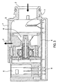
- Figure 3 is a sectional view of another example of a conventional sensor equipped with an aspirator fan motor.
- the sensor includes an air inlet port 2 at a right-hand side of a casing 1, and an air outlet port 3 formed in the top of the casing 1.
- the aspirator fan motor 4 having a plurality of blades for producing an airflow from the air inlet port 2 to the air outlet port 3 is mounted in a central portion of the casing 1.
- a brushless motor excellent in quietness is used for a section of the aspirator fan motor 4.
- Space between the upstream side of the aspirator fan motor 4 and the air inlet port 2 forms a measurement chamber 5.
- a mounting board 6 is arranged at the bottom of the casing 1.
- a thermistor 7 as a temperature-sensing element and a brushless motor drive circuit for the aspirator fan motor 4.
- the mounting board 6 is connected to contact pins 9 of a connector 8. These contact pins 9 are connected to the output terminals of the thermistor 7, the power terminals of the brushless motor drive circuit, etc.
- the thermistor 7 detects the air temperature.
- a signal indicative of the detected temperature is supplied to the control system of an automotive air conditioner via the contact pins 9 of the connector 8, and will be used for control of the temperature within the vehicle cabin.
- a humidity sensor is conventionally arranged e.g. at a rear seat within the vehicle cabin.
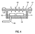
- Figure 4 is a sectional view of a conventional humidity sensor including a humidity-sensing element 11 and a conversion circuit 12 which are mounted on a mounting board 13 accommodated within a casing 14.
- the casing 14 has circulation holes 15.
- Connected to the mounting board 13 is a cable 16 comprised on an output signal line and a power line connected to the control system of the automotive air conditioner.
- the humidity sensor is mounted with mounting screws 17.
- the humidity-sensing element 11 may be of a capacitance type comprising a humidity-sensitive high-polymer membrane formed on a silicon substrate and electrodes formed on the surfaces of the silicon substrate and the humidity-sensitive high-polymer membrane.
- the humidity-sensitive high-polymer has a dielectric constant far smaller than that of water. The dielectric constant largely increases when the polymer absorbs moisture.
- electronic circuit components such as a power supply circuit and an element coping with electromagnet interference, which has been necessitated by the humidity sensor are provided by the shared used of the electronic circuit components such as a power supply circuit and an element coping with electromagnet interference which have been employed in a drive circuit of the aspirator fan motor.
- the sensor in Figures 1 and 2 is equipped with an aspirator fan motor 4 and includes an air inlet port 2 at one end of a casing 1 which has an aspirator duct connected thereto for introducing air to be measured, and an air outlet port 3 formed in the top of the casing 1 for exhausting the air measured.
- the aspirator fan motor 4 is arranged in a central portion of the casing 1, for producing an airflow from the air inlet port 2 to the air outlet port 3.
- the aspirator fan motor 4 is comprised of a brushless DC motor including a magnet 21, a coil block 22 with a search coil for detecting rotation of the motor and a drive coil for driving the motor for rotation arranged theraround, and yokes 23, 24 and an impeller provided for the brushless DC motor and having a plurality of blades 25 and a holding portion for holding the magnet 21. Space between the upstream side of the aspirator fan motor 4 and the air inlet port 2 forms a measurement chamber 5.
- a mounting board 6 is arranged at the bottom of the casing 1.
- a thermistor 7 arranged within the measurement chamber 5 as a temperature-sensing element, a humidity sensor 30, and a brushless motor drive circuit for the aspirator fan motor 4.
- a capacitance type sensor including a humidity-sensing element 31 is employed and a conversion circuit integrally formed with the humidity-sensing element for converting changes in the capacitance dependent on the humidity into a voltage signal or a frequency signal.
- the casing 1 has a connector 8 arranged therein for electrical connection between the sensors and the control system of the automotive air conditioner, and a plurality of contact pins 9 provided therein are soldered to the mounting board 6.
- These contact pins 9 are formed by temperature signal output terminals for a temperature signal from the thermistor 7, power terminals for the brushless motor drive circuit and the humidity sensor, a rotational state output signal output terminal for outputting a signal indicative of a rotational state of the motor and a humidity signal output terminal for the humidity sensor 30.
- the thermistor 7 is arranged within the measurement chamber 5 detects the temperature of the air which flows thereto from the air inlet port 2 and the humidity sensor 30 detects the humidity of the air.
- a signal indicative of temperature detected by the thermistor 7 and a signal indicative of humidity detected by the humidity sensor 30 are supplied to the control system of the automotive air conditioner via the contact pins 9 of the connector 8, and used for control of the temperature within the vehicle cabin and the like.
- the mounting board 6 in Figure 2 has six terminals connected to the contact pins 9 of the connector 8. That is, it has the temperature signal output terminals T-OUT, the power terminals ⁇ V, the rotational state signal output terminal SG-OUT, and the humidity signal output terminal H-OUT.
- the temperature signal output terminals T-OUT are directly connected to two terminals of the thermistor 7 and a capacitor C1 is connected in parallel to the terminals of the thermistor 7, for absorbing high-frequency noise.
- a filter circuit 41 formed by a resistance R1 and a capacitor C2, for absorbing surge voltage superposed on the power line.
- the filter circuit 41 is connected to the power input of the brushless motor drive circuit 43 via a voltage regulator circuit 42 formed by a transistor T, a resistance R2, a Zener diode ZD.
- the rotational state signal output terminal SG-OUT is connected to an output terminal of the brushless motor drive circuit 43 for outputting the rotational state signal, and the rotational state signal output from this terminal is supplied to the control system of the automotive air conditioner where it is used for detecting an abnormal rotational state.
- the humidity signal output terminal H-OUT is connected to a signal output terminal of the humidity sensor 30, and supplies the voltage signal of frequency signal indicative of the humidity detected by the humidity sensor 30 to the control system of the automotive air conditioner.
- the brushless motor derive circuit 43 is connected to the search coil L1 and the drive coil L2 forming the brushless DC motor.
- the search coil L1 detects a voltage induced by rotation of the magnet 21 to thereby detect rotation of the motor, and the drive coil L2 is turned on or off based on the detected rotation of the motor to thereby produce propulsive torque, thereby driving the motor for rotation.
- the humidity sensor 30 is connected to the voltage regulator circuit 42 that supplies power to the brushless motor drive circuit 43 to have power supplied therefrom.
- the filter circuit 41 and the voltage regulator circuit 42 used by the brushless motor drive circuit 43 provision of a power supply and a power line necessary for operating the humidity sensor 30 can be dispensed with so that compared with the case of the humidity sensor 30 being separately provided, the cost of the automotive air conditioner can be reduced.
- the humidity sensor 30 also shares the use of the filter circuit 41, it is unnecessary to provide a special element for coping with electromagnet interference.
- the humidity sensor 30 instead may be arranged at any desired position between the air inlet port 2 and the air outlet port 3.
Landscapes
- Engineering & Computer Science (AREA)
- Mechanical Engineering (AREA)
- General Engineering & Computer Science (AREA)
- Physics & Mathematics (AREA)
- Thermal Sciences (AREA)
- Air-Conditioning For Vehicles (AREA)
- Investigating Or Analyzing Materials By The Use Of Fluid Adsorption Or Reactions (AREA)
- Investigating Or Analyzing Materials By The Use Of Electric Means (AREA)
Description
- This invention relates to a sensor according to the preamble of claim 1.
- Conventionally, some automotive air conditioners sample air temperature at a predetermined position within a vehicle cabin, and perform air conditioning such that the temperature within the vehicle cabin becomes equal to a preset temperature. As a device for detecting the air temperature within the vehicle cabin, a sensor equipped with an aspirator fan motor is known from US-5731953 A, comprising a thermistor as a temperature-sensing element and a motor-driven aspirator fan for forcibly drawing air from an inlet port to the thermistor and from outlet ports. The thermistor, the motor and electronic components for driving the motor, e.g. a drive circuit 7, are mounted on a mounting post in a housing of the sensor.
- Figure 3 is a sectional view of another example of a conventional sensor equipped with an aspirator fan motor. The sensor includes an
air inlet port 2 at a right-hand side of a casing 1, and anair outlet port 3 formed in the top of the casing 1. The aspirator fan motor 4 having a plurality of blades for producing an airflow from theair inlet port 2 to theair outlet port 3 is mounted in a central portion of the casing 1. A brushless motor excellent in quietness is used for a section of the aspirator fan motor 4. Space between the upstream side of the aspirator fan motor 4 and theair inlet port 2 forms ameasurement chamber 5. - A
mounting board 6 is arranged at the bottom of the casing 1. Mounted on themounting board 6 within themeasurement chamber 5 is a thermistor 7 as a temperature-sensing element and a brushless motor drive circuit for the aspirator fan motor 4. Themounting board 6 is connected to contactpins 9 of aconnector 8. Thesecontact pins 9 are connected to the output terminals of the thermistor 7, the power terminals of the brushless motor drive circuit, etc. The thermistor 7 detects the air temperature. A signal indicative of the detected temperature is supplied to the control system of an automotive air conditioner via thecontact pins 9 of theconnector 8, and will be used for control of the temperature within the vehicle cabin. - In some cases, to allow the automotive air conditioner to perform more comfortable air conditioning, the humidity in the air within the vehicle cabin is detected. A humidity sensor is conventionally arranged e.g. at a rear seat within the vehicle cabin. Figure 4 is a sectional view of a conventional humidity sensor including a humidity-
sensing element 11 and aconversion circuit 12 which are mounted on amounting board 13 accommodated within acasing 14. Thecasing 14 hascirculation holes 15. Connected to themounting board 13 is acable 16 comprised on an output signal line and a power line connected to the control system of the automotive air conditioner. The humidity sensor is mounted withmounting screws 17. The humidity-sensing element 11 may be of a capacitance type comprising a humidity-sensitive high-polymer membrane formed on a silicon substrate and electrodes formed on the surfaces of the silicon substrate and the humidity-sensitive high-polymer membrane. The humidity-sensitive high-polymer has a dielectric constant far smaller than that of water. The dielectric constant largely increases when the polymer absorbs moisture. A signal from the humidity-sensing element 11, however, cannot be directly used differently from the signal of the thermistor 7, and hence, theconversion circuit 12 detects and converts changes in the capacitance into a voltage signal or a frequency signal proportional to the change which can be handled by the control system of the automotive air conditioner. - Conventional automotive air conditioners (JP 62-110521 A and JP 2000-351312 A) have a thermistor for detecting temperature and a humidity sensor on the sensor equipped with an aspirator fan motor to reduce the cost of the automotive air conditioner. However, the humidity sensor necessitates a conversion circuit, by its principle, and, therefore, requires provision of a power supply and an element coping with electromagnetic interference for the humidity sensor which increases the cost of the automotive air conditioner.
- It is an object of the invention to provide a low-cost sensor equipped with an aspirator fan motor.
- According to the invention, electronic circuit components such as a power supply circuit and an element coping with electromagnet interference, which has been necessitated by the humidity sensor are provided by the shared used of the electronic circuit components such as a power supply circuit and an element coping with electromagnet interference which have been employed in a drive circuit of the aspirator fan motor. This makes it possible to reduce the number of electronic circuit components necessary for the humidity sensor and provide a more inexpensive automotive air conditioner.
- An embodiment of the invention is explained by way of example with the help of the drawings. In the drawings is:
- Figure 1
- a section of a sensor equipped with an aspirator fan motor according to the invention;
- Figure 2
- a view showing an electric circuit mounted on a mounting board in Figure 1;
- Figure 3
- is a section of a conventional sensor equipped with an aspirator fan motor; and
- Figure 4
- a section of a conventional humidity sensor.
- The sensor in Figures 1 and 2 is equipped with an aspirator fan motor 4 and includes an
air inlet port 2 at one end of a casing 1 which has an aspirator duct connected thereto for introducing air to be measured, and anair outlet port 3 formed in the top of the casing 1 for exhausting the air measured. The aspirator fan motor 4 is arranged in a central portion of the casing 1, for producing an airflow from theair inlet port 2 to theair outlet port 3. The aspirator fan motor 4 is comprised of a brushless DC motor including amagnet 21, acoil block 22 with a search coil for detecting rotation of the motor and a drive coil for driving the motor for rotation arranged theraround, andyokes blades 25 and a holding portion for holding themagnet 21. Space between the upstream side of the aspirator fan motor 4 and theair inlet port 2 forms ameasurement chamber 5. - A
mounting board 6 is arranged at the bottom of the casing 1. Mounted on themounting board 6 are a thermistor 7 arranged within themeasurement chamber 5 as a temperature-sensing element, ahumidity sensor 30, and a brushless motor drive circuit for the aspirator fan motor 4. As thehumidity sensor 30, a capacitance type sensor including a humidity-sensing element 31 is employed and a conversion circuit integrally formed with the humidity-sensing element for converting changes in the capacitance dependent on the humidity into a voltage signal or a frequency signal. - Further, the casing 1 has a
connector 8 arranged therein for electrical connection between the sensors and the control system of the automotive air conditioner, and a plurality ofcontact pins 9 provided therein are soldered to themounting board 6. Thesecontact pins 9 are formed by temperature signal output terminals for a temperature signal from the thermistor 7, power terminals for the brushless motor drive circuit and the humidity sensor, a rotational state output signal output terminal for outputting a signal indicative of a rotational state of the motor and a humidity signal output terminal for thehumidity sensor 30. - When the aspirator fan motor 4 is rotated, an airflow is produced from the
air inlet port 2 to theair outlet port 3. Accordingly, the thermistor 7 is arranged within themeasurement chamber 5 detects the temperature of the air which flows thereto from theair inlet port 2 and thehumidity sensor 30 detects the humidity of the air. A signal indicative of temperature detected by the thermistor 7 and a signal indicative of humidity detected by thehumidity sensor 30 are supplied to the control system of the automotive air conditioner via thecontact pins 9 of theconnector 8, and used for control of the temperature within the vehicle cabin and the like. - The
mounting board 6 in Figure 2 has six terminals connected to thecontact pins 9 of theconnector 8. That is, it has the temperature signal output terminals T-OUT, the power terminals ±V, the rotational state signal output terminal SG-OUT, and the humidity signal output terminal H-OUT. - The temperature signal output terminals T-OUT are directly connected to two terminals of the thermistor 7 and a capacitor C1 is connected in parallel to the terminals of the thermistor 7, for absorbing high-frequency noise. Connected to the power terminals ±V is a
filter circuit 41 formed by a resistance R1 and a capacitor C2, for absorbing surge voltage superposed on the power line. Thefilter circuit 41 is connected to the power input of the brushlessmotor drive circuit 43 via avoltage regulator circuit 42 formed by a transistor T, a resistance R2, a Zener diode ZD. The rotational state signal output terminal SG-OUT is connected to an output terminal of the brushlessmotor drive circuit 43 for outputting the rotational state signal, and the rotational state signal output from this terminal is supplied to the control system of the automotive air conditioner where it is used for detecting an abnormal rotational state. The humidity signal output terminal H-OUT is connected to a signal output terminal of thehumidity sensor 30, and supplies the voltage signal of frequency signal indicative of the humidity detected by thehumidity sensor 30 to the control system of the automotive air conditioner. - The brushless
motor derive circuit 43 is connected to the search coil L1 and the drive coil L2 forming the brushless DC motor. The search coil L1 detects a voltage induced by rotation of themagnet 21 to thereby detect rotation of the motor, and the drive coil L2 is turned on or off based on the detected rotation of the motor to thereby produce propulsive torque, thereby driving the motor for rotation. - The
humidity sensor 30 is connected to thevoltage regulator circuit 42 that supplies power to the brushlessmotor drive circuit 43 to have power supplied therefrom. Thus, through the shared use of thefilter circuit 41 and thevoltage regulator circuit 42 used by the brushlessmotor drive circuit 43, provision of a power supply and a power line necessary for operating thehumidity sensor 30 can be dispensed with so that compared with the case of thehumidity sensor 30 being separately provided, the cost of the automotive air conditioner can be reduced. Further, since thehumidity sensor 30 also shares the use of thefilter circuit 41, it is unnecessary to provide a special element for coping with electromagnet interference. - The
humidity sensor 30 instead may be arranged at any desired position between theair inlet port 2 and theair outlet port 3.
Claims (2)
- A sensor suitable for being used in a vehicle, the sensor being equipped with a motor (4) for an aspirator fan for drawing air between an inlet part (2) and an outlet port (3) and for outputting signals of temperature and humidity for controlling an automotive air conditioner,
a mounting board (6) on which electronic circuit components are mounted for driving the aspirator fan motor (4);
a temperature sensor (7) mounted at a desired position between said inlet and outlet ports (2, 3) on the mounting board (6), for detecting a temperature of the drawn-in air, characterized in that
a humidity sensor (30) is mounted at a desired position between the inlet and outlet ports (2, 3) on the mounting board (6), for detecting a humidity of the drawn-in air,
and that electronic circuit components (40, 42) necessary for operation of the humidity sensor are provided by shared use of electronic circuit components (41, 42) for driving the aspirator fan motor (4). - Sensor according to claim 1, characterized in that power lines of the humidity sensor (30) are provided by shared use of power lines of the aspirator fan motor (4).
Applications Claiming Priority (3)
| Application Number | Priority Date | Filing Date | Title |
|---|---|---|---|
| JP2001078113A JP2002277425A (en) | 2001-03-19 | 2001-03-19 | In-car sensor with suction fan motor |
| JP2001078113 | 2001-03-19 | ||
| PCT/JP2002/001982 WO2002074566A1 (en) | 2001-03-19 | 2002-03-04 | In-car sensor with intake fan motor |
Publications (3)
| Publication Number | Publication Date |
|---|---|
| EP1285790A1 EP1285790A1 (en) | 2003-02-26 |
| EP1285790A4 EP1285790A4 (en) | 2005-12-28 |
| EP1285790B1 true EP1285790B1 (en) | 2006-12-06 |
Family
ID=18934771
Family Applications (1)
| Application Number | Title | Priority Date | Filing Date |
|---|---|---|---|
| EP02701710A Expired - Lifetime EP1285790B1 (en) | 2001-03-19 | 2002-03-04 | In-car sensor with intake fan motor |
Country Status (5)
| Country | Link |
|---|---|
| US (1) | US6622924B2 (en) |
| EP (1) | EP1285790B1 (en) |
| JP (1) | JP2002277425A (en) |
| DE (1) | DE60216546T2 (en) |
| WO (1) | WO2002074566A1 (en) |
Cited By (1)
| Publication number | Priority date | Publication date | Assignee | Title |
|---|---|---|---|---|
| DE102008057366A1 (en) * | 2008-11-14 | 2010-05-27 | Behr-Hella Thermocontrol Gmbh | Sensor for detecting surface wetness at cooling unit of vehicle air conditioning system, has sensor element with electrically conductive surface for formation of capacitor, particularly plate capacitor |
Families Citing this family (18)
| Publication number | Priority date | Publication date | Assignee | Title |
|---|---|---|---|---|
| DE10256001A1 (en) * | 2002-11-30 | 2004-06-17 | Adam Opel Ag | Motor vehicle with a heating and ventilation or air conditioning system |
| DE50303676D1 (en) * | 2003-04-02 | 2006-07-20 | Catem Gmbh & Co Kg | Motor vehicle seat and fan module for such a motor vehicle seat |
| DE10316194B4 (en) * | 2003-04-09 | 2012-10-11 | Webasto Ag | Air heater with a device for flame monitoring |
| JP4129594B2 (en) * | 2003-04-15 | 2008-08-06 | 株式会社日立製作所 | Air conditioning system |
| DE10325971A1 (en) * | 2003-06-07 | 2004-12-23 | E + E Elektronik Ges.M.B.H. | Basic module for several sensor units |
| KR100942937B1 (en) | 2003-06-20 | 2010-02-22 | 한라공조주식회사 | How to adaptively control automotive sensor motors |
| DE102005021708A1 (en) * | 2005-05-11 | 2006-11-16 | Hella Kgaa Hueck & Co. | Sensor arrangement for detecting fogging tendency |
| JP4860793B2 (en) * | 2005-05-19 | 2012-01-25 | 株式会社日本自動車部品総合研究所 | Manufacturing method of humidity sensor |
| US20070039335A1 (en) * | 2005-08-18 | 2007-02-22 | Samsung Electronics Co.,Ltd. | Icemaker and refrigerator comprising the same |
| US20090060738A1 (en) * | 2007-08-31 | 2009-03-05 | Delta Electronics, Inc. | Fan and manufacturing method thereof |
| JP4924958B2 (en) | 2009-11-02 | 2012-04-25 | 株式会社デンソー | Alcohol concentration detector |
| ITTO20110047U1 (en) * | 2011-06-03 | 2012-12-04 | Bitron Spa | TEMPERATURE AND HUMIDITY VENTILATED SENSOR DEVICE FOR THE USE OF A MOTORCYCLE ON BOARD |
| USD703301S1 (en) | 2011-08-08 | 2014-04-22 | Ebm-Papst St. Georgen Gmbh & Co. Kg | Axial fan |
| JP2013132962A (en) * | 2011-12-26 | 2013-07-08 | Denso Corp | Vehicle air conditioner |
| CN102797694A (en) * | 2012-08-03 | 2012-11-28 | 张天河 | Electric fan |
| CN102979742A (en) * | 2012-12-13 | 2013-03-20 | 庄森安 | Auto-induction type fog exhaust fan |
| TWI659159B (en) * | 2018-01-31 | 2019-05-11 | 建準電機工業股份有限公司 | Temperature-detecting fan |
| TWI699166B (en) * | 2019-01-02 | 2020-07-21 | 愛利奧有限公司 | Bean body temperature detecting element and its temperature measuring method |
Family Cites Families (13)
| Publication number | Priority date | Publication date | Assignee | Title |
|---|---|---|---|---|
| JPS6191416A (en) | 1984-10-12 | 1986-05-09 | Nikkei Tomakomai Kk | Modifying method of scale produced upon combustion of oil coke |
| JPS6191416U (en) * | 1984-11-22 | 1986-06-13 | ||
| JPS61183714A (en) | 1985-02-08 | 1986-08-16 | Hitachi Ltd | Mobil robot |
| JPS61183713A (en) | 1985-02-12 | 1986-08-16 | Toshiba Corp | Measurement control device |
| JPS61183714U (en) * | 1985-05-10 | 1986-11-15 | ||
| JPS61183713U (en) * | 1985-05-10 | 1986-11-15 | ||
| JPS62110521A (en) * | 1985-11-08 | 1987-05-21 | Matsushita Electric Ind Co Ltd | Temperature and humidity detection device for vehicle air conditioners |
| JP3137525B2 (en) * | 1994-02-23 | 2001-02-26 | カルソニックカンセイ株式会社 | Automotive air conditioners |
| US5578753A (en) * | 1995-05-23 | 1996-11-26 | Micro Weiss Electronics, Inc. | Humidity and/or temperature control device |
| JP3624035B2 (en) | 1995-10-30 | 2005-02-23 | 株式会社アイチコーポレーション | Control system for taillights and brake lights of work vehicles for track and land |
| JPH09123732A (en) * | 1995-11-01 | 1997-05-13 | Zexel Corp | Air conditioner for automobile |
| JP2000351312A (en) * | 1999-06-10 | 2000-12-19 | Denso Corp | Temperature and humidity detector for vehicles |
| US6347746B1 (en) * | 2000-03-03 | 2002-02-19 | Visteon Global Technologies, Inc. | Temperature and humidity sensor assembly |
-
2001
- 2001-03-19 JP JP2001078113A patent/JP2002277425A/en active Pending
-
2002
- 2002-03-04 WO PCT/JP2002/001982 patent/WO2002074566A1/en not_active Ceased
- 2002-03-04 DE DE60216546T patent/DE60216546T2/en not_active Expired - Fee Related
- 2002-03-04 EP EP02701710A patent/EP1285790B1/en not_active Expired - Lifetime
- 2002-09-19 US US10/247,210 patent/US6622924B2/en not_active Expired - Fee Related
Cited By (2)
| Publication number | Priority date | Publication date | Assignee | Title |
|---|---|---|---|---|
| DE102008057366A1 (en) * | 2008-11-14 | 2010-05-27 | Behr-Hella Thermocontrol Gmbh | Sensor for detecting surface wetness at cooling unit of vehicle air conditioning system, has sensor element with electrically conductive surface for formation of capacitor, particularly plate capacitor |
| DE102008057366B4 (en) * | 2008-11-14 | 2011-02-03 | Behr-Hella Thermocontrol Gmbh | Sensor for detecting a surface moisture on a cooling unit of a motor vehicle air conditioning unit and cooling unit for a motor vehicle air conditioning system with such a sensor |
Also Published As
| Publication number | Publication date |
|---|---|
| US6622924B2 (en) | 2003-09-23 |
| EP1285790A1 (en) | 2003-02-26 |
| DE60216546T2 (en) | 2007-04-05 |
| WO2002074566A1 (en) | 2002-09-26 |
| US20030019223A1 (en) | 2003-01-30 |
| EP1285790A4 (en) | 2005-12-28 |
| DE60216546D1 (en) | 2007-01-18 |
| JP2002277425A (en) | 2002-09-25 |
Similar Documents
| Publication | Publication Date | Title |
|---|---|---|
| US6622924B2 (en) | In-car sensor equipped with aspirator fan motor | |
| KR100214372B1 (en) | Car air conditioners | |
| JP4975931B2 (en) | Improved heating / ventilation / air conditioning systems for vehicles | |
| US9271422B2 (en) | Drive apparatus | |
| US6397609B1 (en) | Vehicle air-conditioning system with arrangement of electrical member | |
| US4857784A (en) | Motor having rotation speed detection mechanism | |
| JP6691599B2 (en) | Motor for fan or ventilator, pump or compressor, method of operating that motor, and ventilation system with one or more motors / ventilators | |
| CN107528426B (en) | Rotating device and vehicle equipped with air-conditioning system having the same | |
| US20070040463A1 (en) | Drive for the adjustment of flaps | |
| US8251655B2 (en) | Fan and frame with sensor-supporting structure thereof | |
| US20060164030A1 (en) | Motor actuator | |
| US20080100237A1 (en) | Dual fan module system with three power options using two single throw relays and one double throw relay and a series resistor | |
| JP3920454B2 (en) | Brushless fan motor | |
| JPH07232543A (en) | Automobile air conditioner | |
| JP2003134720A (en) | Actuator connector | |
| CN101861696B (en) | Motor current calculation device and air conditioning device | |
| EP0768212A2 (en) | Control module | |
| CN219659547U (en) | Motor device, electric driving system and automobile | |
| JP4083294B2 (en) | Brushless motor | |
| JPS628812A (en) | Air conditioner for vehicles | |
| AU2001237111B2 (en) | Improvements in heating/ventilating/air conditioning systems for vehicles | |
| JP2004248438A (en) | Motor control device | |
| JP2023151148A (en) | Automotive power converter | |
| CN106979826B (en) | Sensor module, electric machine, power electronics and vehicle | |
| US20190280572A1 (en) | Actuation Device |
Legal Events
| Date | Code | Title | Description |
|---|---|---|---|
| PUAI | Public reference made under article 153(3) epc to a published international application that has entered the european phase |
Free format text: ORIGINAL CODE: 0009012 |
|
| 17P | Request for examination filed |
Effective date: 20021007 |
|
| AK | Designated contracting states |
Kind code of ref document: A1 Designated state(s): AT BE CH CY DE DK ES FI FR GB GR IE IT LI LU MC NL PT SE TR |
|
| A4 | Supplementary search report drawn up and despatched |
Effective date: 20051115 |
|
| RIC1 | Information provided on ipc code assigned before grant |
Ipc: 7G 01N 27/04 B Ipc: 7B 60H 1/00 A |
|
| GRAP | Despatch of communication of intention to grant a patent |
Free format text: ORIGINAL CODE: EPIDOSNIGR1 |
|
| RBV | Designated contracting states (corrected) |
Designated state(s): DE ES FR GB IT |
|
| GRAS | Grant fee paid |
Free format text: ORIGINAL CODE: EPIDOSNIGR3 |
|
| GRAA | (expected) grant |
Free format text: ORIGINAL CODE: 0009210 |
|
| AK | Designated contracting states |
Kind code of ref document: B1 Designated state(s): DE ES FR GB IT |
|
| PG25 | Lapsed in a contracting state [announced via postgrant information from national office to epo] |
Ref country code: IT Free format text: LAPSE BECAUSE OF FAILURE TO SUBMIT A TRANSLATION OF THE DESCRIPTION OR TO PAY THE FEE WITHIN THE PRESCRIBED TIME-LIMIT;WARNING: LAPSES OF ITALIAN PATENTS WITH EFFECTIVE DATE BEFORE 2007 MAY HAVE OCCURRED AT ANY TIME BEFORE 2007. THE CORRECT EFFECTIVE DATE MAY BE DIFFERENT FROM THE ONE RECORDED. Effective date: 20061206 |
|
| REG | Reference to a national code |
Ref country code: GB Ref legal event code: FG4D |
|
| REF | Corresponds to: |
Ref document number: 60216546 Country of ref document: DE Date of ref document: 20070118 Kind code of ref document: P |
|
| PG25 | Lapsed in a contracting state [announced via postgrant information from national office to epo] |
Ref country code: ES Free format text: LAPSE BECAUSE OF FAILURE TO SUBMIT A TRANSLATION OF THE DESCRIPTION OR TO PAY THE FEE WITHIN THE PRESCRIBED TIME-LIMIT Effective date: 20070317 |
|
| ET | Fr: translation filed | ||
| PLBE | No opposition filed within time limit |
Free format text: ORIGINAL CODE: 0009261 |
|
| STAA | Information on the status of an ep patent application or granted ep patent |
Free format text: STATUS: NO OPPOSITION FILED WITHIN TIME LIMIT |
|
| 26N | No opposition filed |
Effective date: 20070907 |
|
| GBPC | Gb: european patent ceased through non-payment of renewal fee |
Effective date: 20070306 |
|
| PG25 | Lapsed in a contracting state [announced via postgrant information from national office to epo] |
Ref country code: GB Free format text: LAPSE BECAUSE OF NON-PAYMENT OF DUE FEES Effective date: 20070306 |
|
| PGFP | Annual fee paid to national office [announced via postgrant information from national office to epo] |
Ref country code: DE Payment date: 20090429 Year of fee payment: 8 |
|
| PGFP | Annual fee paid to national office [announced via postgrant information from national office to epo] |
Ref country code: FR Payment date: 20090325 Year of fee payment: 8 |
|
| REG | Reference to a national code |
Ref country code: FR Ref legal event code: ST Effective date: 20101130 |
|
| PG25 | Lapsed in a contracting state [announced via postgrant information from national office to epo] |
Ref country code: FR Free format text: LAPSE BECAUSE OF NON-PAYMENT OF DUE FEES Effective date: 20100331 |
|
| PG25 | Lapsed in a contracting state [announced via postgrant information from national office to epo] |
Ref country code: DE Free format text: LAPSE BECAUSE OF NON-PAYMENT OF DUE FEES Effective date: 20101001 |