EP1285696B1 - Jaw crusher - Google Patents
Jaw crusher Download PDFInfo
- Publication number
- EP1285696B1 EP1285696B1 EP02017752A EP02017752A EP1285696B1 EP 1285696 B1 EP1285696 B1 EP 1285696B1 EP 02017752 A EP02017752 A EP 02017752A EP 02017752 A EP02017752 A EP 02017752A EP 1285696 B1 EP1285696 B1 EP 1285696B1
- Authority
- EP
- European Patent Office
- Prior art keywords
- jaw
- hydraulic cylinder
- movable jaw
- piston
- frame
- Prior art date
- Legal status (The legal status is an assumption and is not a legal conclusion. Google has not performed a legal analysis and makes no representation as to the accuracy of the status listed.)
- Expired - Lifetime
Links
- 230000008878 coupling Effects 0.000 abstract description 20
- 238000010168 coupling process Methods 0.000 abstract description 20
- 238000005859 coupling reaction Methods 0.000 abstract description 20
- 238000005299 abrasion Methods 0.000 abstract description 6
- NJPPVKZQTLUDBO-UHFFFAOYSA-N novaluron Chemical compound C1=C(Cl)C(OC(F)(F)C(OC(F)(F)F)F)=CC=C1NC(=O)NC(=O)C1=C(F)C=CC=C1F NJPPVKZQTLUDBO-UHFFFAOYSA-N 0.000 description 12
- 238000006243 chemical reaction Methods 0.000 description 4
- 230000000694 effects Effects 0.000 description 3
- 239000000314 lubricant Substances 0.000 description 3
- 238000012423 maintenance Methods 0.000 description 3
- 210000002445 nipple Anatomy 0.000 description 3
- 230000006835 compression Effects 0.000 description 2
- 238000007906 compression Methods 0.000 description 2
- 230000008602 contraction Effects 0.000 description 2
- 238000010586 diagram Methods 0.000 description 2
- 238000005265 energy consumption Methods 0.000 description 2
- 238000005461 lubrication Methods 0.000 description 2
- 230000002265 prevention Effects 0.000 description 2
- 230000002787 reinforcement Effects 0.000 description 2
- 239000000126 substance Substances 0.000 description 2
- 230000004323 axial length Effects 0.000 description 1
- 230000003247 decreasing effect Effects 0.000 description 1
- 230000001419 dependent effect Effects 0.000 description 1
- 238000000034 method Methods 0.000 description 1
- 239000011435 rock Substances 0.000 description 1
- 239000013585 weight reducing agent Substances 0.000 description 1
Images


Classifications
-
- B—PERFORMING OPERATIONS; TRANSPORTING
- B02—CRUSHING, PULVERISING, OR DISINTEGRATING; PREPARATORY TREATMENT OF GRAIN FOR MILLING
- B02C—CRUSHING, PULVERISING, OR DISINTEGRATING IN GENERAL; MILLING GRAIN
- B02C1/00—Crushing or disintegrating by reciprocating members
- B02C1/02—Jaw crushers or pulverisers
- B02C1/04—Jaw crushers or pulverisers with single-acting jaws
-
- B—PERFORMING OPERATIONS; TRANSPORTING
- B02—CRUSHING, PULVERISING, OR DISINTEGRATING; PREPARATORY TREATMENT OF GRAIN FOR MILLING
- B02C—CRUSHING, PULVERISING, OR DISINTEGRATING IN GENERAL; MILLING GRAIN
- B02C1/00—Crushing or disintegrating by reciprocating members
- B02C1/005—Crushing or disintegrating by reciprocating members hydraulically or pneumatically operated
-
- B—PERFORMING OPERATIONS; TRANSPORTING
- B02—CRUSHING, PULVERISING, OR DISINTEGRATING; PREPARATORY TREATMENT OF GRAIN FOR MILLING
- B02C—CRUSHING, PULVERISING, OR DISINTEGRATING IN GENERAL; MILLING GRAIN
- B02C1/00—Crushing or disintegrating by reciprocating members
- B02C1/02—Jaw crushers or pulverisers
- B02C1/025—Jaw clearance or overload control
-
- B—PERFORMING OPERATIONS; TRANSPORTING
- B02—CRUSHING, PULVERISING, OR DISINTEGRATING; PREPARATORY TREATMENT OF GRAIN FOR MILLING
- B02C—CRUSHING, PULVERISING, OR DISINTEGRATING IN GENERAL; MILLING GRAIN
- B02C13/00—Disintegrating by mills having rotary beater elements ; Hammer mills
-
- B—PERFORMING OPERATIONS; TRANSPORTING
- B02—CRUSHING, PULVERISING, OR DISINTEGRATING; PREPARATORY TREATMENT OF GRAIN FOR MILLING
- B02C—CRUSHING, PULVERISING, OR DISINTEGRATING IN GENERAL; MILLING GRAIN
- B02C13/00—Disintegrating by mills having rotary beater elements ; Hammer mills
- B02C13/02—Disintegrating by mills having rotary beater elements ; Hammer mills with horizontal rotor shaft
- B02C13/06—Disintegrating by mills having rotary beater elements ; Hammer mills with horizontal rotor shaft with beaters rigidly connected to the rotor
- B02C13/09—Disintegrating by mills having rotary beater elements ; Hammer mills with horizontal rotor shaft with beaters rigidly connected to the rotor and throwing the material against an anvil or impact plate
Definitions
- the present invention relates to a jaw crusher, according to the preamble of claim 1.
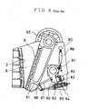
- FIG. 8 is an explanatory view in a side section of a crusher disclosed in Japanese Patent Application Publication No. 5-45300.
- a swing jaw 61 having a movable jaw 5 is suspended from an eccentric shaft 62, and a stationary jaw 3 is attached to oppose it.
- a lower end portion of a toggle block 63 is rotatably attached to the crusher main body 60 with a pin 64.
- a base end portion of a hydraulic actuator 70 having a frictional force utilizing close fit of a sleeve and a cylinder rod is swingably attached to the crusher main body 60, and its tip end portion is rotatably attached at an upper end portion of the toggle block 63 with a pin 65.
- An adjusting hydraulic cylinder 71 is provided in series at a rear end portion of the hydraulic actuator 70.
- Toggle sheets 66 and 66 each having a groove portion are provided at a lower end portion of the swing jaw 61 and at a center portion of the toggle block 63, and a toggle plate 67 is inserted between the groove portions of both the sheets 66 and 66 with both end portions being slidable.
- a spring 68 is biased so that the swing jaw 61 and the toggle block 63 always hold the toggle plate 67 between them.
- Hydraulic pressure of the adjusting hydraulic cylinder 71 is adjusted at a predetermined set pressure during a crushing operation so that the cylinder rod of the hydraulic actuator 70 is held at an arbitrary position by a frictional force of the sleeve and the cylinder rod, and a clearance between tip end portions of the movable jaw 5 and the stationary jaw 3 is maintained.
- FIG. 9 is an explanatory view of a sectional side view of a jaw crusher disclosed in Japanese Patent Application Laid-open No. 10-249224.
- a swing jaw 61 having the movable jaw 5 is swingably suspended at an eccentric shaft 62 attached at upper portions of left and right side frames 80 and 80, and the stationary jaw 3 is fixedly provided at the side frame 80 to oppose it to form a crushing chamber 6.
- a toggle block 63 is attached to the side frame 80 by a block support shaft 81 with its base end portion being rotatable.
- a window 82 having a semicircular portion is provided near a tip end portion of the toggle block 63 at the side frame 80, a semicircular disc-shaped load supporting plate 83 is fitted in the window 82, and a set adjusting plate 84 for adjusting an outlet clearance of the crushing chamber 6 is provided between the load supporting plate 83 and the toggle block 63.
- Toggle sheets 66 and 66 each having a groove portion are attached to a lower end portion of the swing jaw 61 and the toggle block 63.
- a toggle plate 67 is provided between groove portions of both the sheets 66 and 66 so that both ends thereof is slidable, and the lower end portion of the swing jaw 61 is always biased to the toggle block 63 by a spring 85.
- the toggle block 63 and the side frame 80 are connected by a bare rock type of hydraulic cylinder 86, the toggle block 63 is rotated by a hydraulic cylinder 86 at the time of adjusting the outlet clearance of the crushing chamber 6, and a clearance is provided between the toggle block 63 and the load supporting plate 83 so that the thickness of the set adjusting plate 84 is adjusted.
- the toggle sheets 66 and 66 are attached to the lower end portion of the swing jaw 61 and the toggle block 63, and the toggle plate 67 is held between both the sheets 66 and 66 to receive a load during crushing. Accordingly, the toggle plate 67 is sandwiched, and the springs 68 and 85 are used to hold it, which makes the structures complicated, requires adjustment of the springs 68 and 85 each time the tip clearance is adjusted, thus increasing adjustment time. In addition, when they are mounted on vehicles, operating spaces become narrow, which makes adjusting operations themselves difficult.
- the adjusting hydraulic cylinder 71 is provided at the rear end portion of the hydraulic actuator 70, the total length of the hydraulic cylinder part is long, and since it is horizontally arranged, a total length N of the jaw crusher 61 shown in FIG. 8 is long, which makes a space area large to cause the disadvantage when mounted on a vehicle and the like. Since pressure is always applied to the adjusting hydraulic cylinder 71, energy is wasted. Further, oil leakage occurs, which makes it unstable. A complicated hydraulic circuit structure is necessary to prevent the oil leakage, which makes it expensive.
- the toggle plate 67 is sandwiched, and the springs 68 and 85 are used to hold it, which makes the structures complicated, requires adjustment of the springs 68 and 85 each time the tip clearance is adjusted, thus increasing adjustment time.
- the toggle plate 67 is bent under excessive load, and a replacement operation of the bent toggle plate 67 is difficult, thus requiring a great deal of time.
- adjustment of the outlet clearance of the crushing chamber 6 is made with the set adjustment plate 84, a great deal of time is required for adjustment and thus operation efficiency is low.
- a jaw crusher of the initially-mentioned type and having the features of the preamble of claim 1 is known from DE 44 00 922 A.
- the present invention is made in view of the above-described disadvantages, and has its object to provide a compact and light-weight jaw crusher in which life span of parts enduring abrasion is long, a structure is simple, less part is damaged under excessive load with excellent operation efficiency, greater economy is obtained with no energy loss, and an outlet clearance of a crushing chamber is easily adjusted.
- the swingable coupling joint which never comes off and falls, is used for the connecting member for the lower end portion of the movable jaw which receives load during compression crushing of the jaw crusher and the movable jaw load receiving section attached to the frame. Consequently, since the attached spring is not needed, the structure is simplified, and the tip clearance adjusting time can be shortened. Further, the lubrication at the connecting portion is secured, and the frequency of maintenance is reduced with less abrasion, thus improving operation efficiency.
- the structure including a hydraulic circuit which makes the hydraulic cylinder with the close fit mechanism open at a time of crushing operation may be made.
- the hydraulic cylinder with the close fit mechanism has the structure having the close fit mechanism of the piston and the cylinder.
- the hydraulic cylinder with the close fit mechanism has the close fit mechanism of the piston and the cylinder, the relative movement in the axial direction is locked with the frictional force by the close fitting and the length in the axial direction is made changeable by hydraulic pressure applied to both end portions of the piston.
- a large locking force can be obtained with a small size and the total length can be reduced, thus making it possible to reduce the apparatus in size.
- the hydraulic cylinder with the close fit mechanism has the close fit mechanism of the piston and the cylinder, locks the relative movement in the axial direction with the friction force by the close fitting, and makes the length in the axial direction changeable by the hydraulic pressure applied to both end portions of the piston, thus making it possible to obtain a large locking force with a small size, reduce the total length, and make the apparatus compact.
- the structure in which one end portion of the hydraulic cylinder with the close fit mechanism is attached to the frame near the eccentric drive shaft may be made.
- one end portion of the hydraulic cylinder with the close fit mechanism is attached to the frame near the eccentric drive shaft having rigidity, and therefore special reinforcement of the frame for attachment of the hydraulic cylinder becomes unnecessary, thus making it possible to reduce in weight. Further, placement in the substantially vertical direction is made possible, whereby the total length of the jaw crusher can be reduced, the frame can be reduced in weight, and the jaw crusher can be easily mounted on a vehicle.
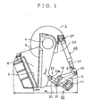
- FIG. 1 is a partial sectional side view showing an example of a jaw crusher 1.
- a stationary jaw 3 is attached between a pair of left and right frames 2 and 2
- a movable jaw 5 is swingably suspended at an eccentric drive shaft 4 provided at frames 2 and 2 at a position opposing the stationary jaw 3, whereby a crushing chamber 6 is formed between the stationary jaw 3 and the movable jaw 5.
- a movable jaw load receiving section 10 forming a link mechanism is provided at a back of the movable jaw 5 between the frames 2 and 2.
- a longitudinal middle portion of a lever 12 is swingably attached to a bracket 11 fixedly provided at the frames 2 and 2 by means of a first pin 13.
- One end portion of a link 20 is attached to one end portion of the lever 12 by means of a second pin 21 as an example of a pin coupling joint, and the other end portion of the link 20 is rotatably connected to a lower portion of the back side of the movable jaw 5 by means of a third pin 23a as an example of the pin coupling joint.
- the link 20, the second pin 21 and the third pin 23a form a coupling joint 23 for swingably connecting the lower portion of the movable jaw 5 and the movable jaw load receiving section 10.
- the other end portion of the lever 12 is rotatably connected to a tip end portion of a piston rod 41 of a hydraulic cylinder 40 with a close fit mechanism by means of a fourth pin 25.
- the hydraulic cylinder 40 with the close fit mechanism is placed with its cylinder shaft being faced in substantially a vertical direction, and its base end portion is rotatably attached to an upper portion of the frame 2 by means of a fifth pin 27.
- a reaction force occurring when an object to be crushed is crushed in the crushing chamber 6 is transmitted to the hydraulic cylinder 40 with the close fit mechanism via the link 20 and the lever 12.
- the lever 12, the hydraulic cylinder 40 with the close fit mechanism, the bracket 11 and each of the connecting pins 13, 25 and 27 form the movable jaw load receiving section 10.
- the eccentric drive shaft 4, the movable jaw load receiving section 10 and the coupling joint 23 constitute a movable jaw holding mechanism for holding the movable jaw 5 at the frame 2.
- the coupling joint 23 is an example of a connecting member for connecting the movable jaw 5 and the movable jaw load receiving section 10.
- FIG. 2 is a sectional view taken along the line 2-2 in FIG. 1, and the detail of a connecting portion of the link 20 and the lever 12 will be explained with reference to FIG. 2.
- two of the aforementioned brackets 11, levers 12, links 20, and hydraulic cylinders 40 each with the close fit mechanism, having the same structure, are provided in parallel on the left and right (up and down in FIG. 2) of the movable jaw 5.
- a first bush 14 is provided between the bracket 11 and the first pin 13, and lubricant oil is supplied to the first bush 14 from a nipple 15.
- a second bush 22 is provided between the one end portion of the link 20 and the second pin 21, and lubricant oil is supplied to the second bush 22 from a nipple 15a.
- a third bush 24 is provided between the other end portion of the link 20 and the third pin 23a, and lubricant oil is supplied to the third bush 24 from a nipple 15b.
- a ball bearing 26 is provided at the forth pin 25 portion for connecting the other end portion of the lever 12 and the tip end portion of the piston rod 41 of the hydraulic cylinder 40 with the close fit mechanism.
- FIG. 3 is a sectional view of the hydraulic cylinder 40 with the close fit mechanism.
- a piston 43 having a piston rod 41 is pressed into a cylinder 42.
- An oil hole 44 is formed in the piston rod 41, and the oil hole 44 is communicated with an outside surface of the piston 43.
- FIG. 3 shows a state in which pressure oil is not supplied to the oil hole 44 from outside, and in this state, the piston 43 is in a fixed position with frictional resistance with the cylinder 42.
- pressure oil is supplied into the oil hole 44 so that the cylinder 42 area at the outer circumferential part of the piston 43 is expanded as a section P shown in FIG. 4 to expand the inner diameter.
- the frictional resistance between the piston 43 and the cylinder 42 is reduced, whereby the press fitting force of the piston 43 is reduced, and subsequently, the pressure oil is supplied to a cylinder head chamber 45 or a cylinder bottom chamber 46 to thereby move the piston 43.
- a first electromagnetic change-over valve 52 is provided on a piston circuit 51 for connecting the oil hole 44 of the piston rod 41 of the hydraulic cylinder 40 with the close fit mechanism and a first oil hydraulic source 50.
- a second electromagnetic change-over valve 56 is provided on a head circuit 54 and a bottom circuit 55 for connecting the cylinder head chamber 45 and the cylinder bottom chamber 46 of the hydraulic cylinder 40 with the close fit mechanism to a second oil hydraulic source 53.
- the first electromagnetic change-over valve 52 has two positions a and b shown in FIG. 5, the piston circuit 51 is connected to a tank 59 at the position a, and the circuit 51 is connected to a discharge circuit of the first oil hydraulic source 50 at the position b.
- the second electromagnetic change-over valve 56 has three positions c, d and e shown in FIG. 5, the head circuit 54 is connected to the second oil hydraulic source 53 at the position c, the head circuit 54 and the bottom circuit 55 are connected to the tank 59 at the position d, and the bottom circuit 55 is connected to the second oil hydraulic source 53 at the position e.
- an operation lever 57 for operating the hydraulic cylinder 40 with the close fit mechanism to contract and extend is provided, and an operation signal of the operation lever 57 is electrically connected to the first electromagnetic change-over valve 52 and the second electromagnetic change-over valve 56 via a controller 58.
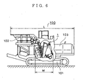
- FIG. 6 is a partial sectional view of a self-propelled jaw crusher 100 of an example, on which the jaw crusher 1 of the first embodiment is mounted.
- the jaw crusher 1 is mounted on a top portion in the middle of a traveling unit 101, and a hopper 102 is mounted in front thereof, while a power source 103 is mounted behind it. Accordingly, a total length M of the jaw crusher 1 is shorter than the length N of the conventional one shown in FIG. 8 as described above, and therefore a total length L of the self-propelled jaw crusher 100 can be made shorter and compact.
- the first electromagnetic change-over valve 52 is firstly switched into the position b to feed pressure oil into the oil hole 44 of the hydraulic cylinder 40 with the close fit mechanism to reduce the frictional force between the cylinder 42 and the piston 43.
- the second electromagnetic change-over valve 56 is switched into the position c or the position e to apply predetermined pushing pressure P1 to the head chamber 40a or the bottom chamber 40b of the hydraulic cylinder 40 with the close fit mechanism to contract or extend the hydraulic cylinder 40 with the close fit mechanism.
- the movable jaw 5 is swung via the lever 12 and the coupling joint 23 to adjust an outlet clearance S at the tip end portion of the stationary jaw 3 and the movable jaw 5 shown in FIG. 1 in accordance with a product.
- the second electromagnetic change-over valve 56 is switched into the position d to connect the head circuit 54 and the bottom circuit 55 to the tank 59, and the head chamber 40a and the bottom chamber 40b of the hydraulic cylinder 40 with the close fit mechanism are opened to make the pushing pressure P1 zero.
- the movable jaw load receiving section 10 (the lever 12, the hydraulic cylinder 40 with the close fit mechanism, the bracket 11 and each of the connecting pins 13, 25 and 27) and the coupling joint 23 form a part of the clearance adjusting mechanism.
- the jaw crusher 1 according to the first embodiment of the present invention is constituted as described above, the following effects can be obtained.
- the structure is simplified, and lubrication of the connecting portion can be surely made, whereby abrasion is reduced and thus the frequency of maintenance is reduced, thus improving operation efficiency.
- the hydraulic cylinder 40 with the close fit mechanism includes the cylinder 42, the piston 43 and the piston rod 41, it locks the relative movement in the axial direction by the frictional force by the close fitting of the piston 43 and the cylinder 42, and it makes the axial length changeable by the hydraulic pressure applied to both end portions of the piston 43. As a result, large locking power can be obtained with the smaller size, and the total length can be reduced, thus reducing the apparatus in size and weight.
- the pressure oil is not applied to the hydraulic cylinder 40 with the close fit mechanism during a crushing operation, greater economy is obtained with no energy loss, and an accumulator for holding the pressure oil, a leakage prevention valve and the like are not needed in the hydraulic circuit, whereby the circuit is simplified and the cost is reduced.
- the shaft of the hydraulic cylinder 40 with the close fit mechanism is placed in the substantially vertical direction, the total length M of the jaw crusher 1 can be reduced, whereby the frame 2 can be reduced in weight and the vehicle can be made compact when it is mounted thereon.
- the connecting portion (the fifth pin 27 portion) with the frame 2 is provided near the eccentric drive shaft 4 having rigidity, special rigidity reinforcement for the frame 2 is not needed and weight reduction can be realized.
- pin coupling (by the third pin 23a shown in the drawing) is used for the coupling joint 23 of the lower portion of the movable jaw 5 and the movable jaw load receiving section 10, but they may be connected with a trunnion joint, a universal joint, a joint with use of a ball bearing or the like.
- An example in which two of the brackets 11, the levers 12, the links 20 and the hydraulic cylinders 40 each with the close fit mechanism are provided in parallel is shown, but this is not restrictive, and they may be constituted by an integrated one or by each single unit of them.
- the piston rod 41 of the hydraulic cylinder 40 with the close fit mechanism may be attached in the opposite direction.
- the number of links of the movable jaw load receiving section 10 forming the link mechanism is not limited to the above-described embodiment.
- a stationary jaw 3 is attached to a pair of left and right frames 2 and 2, and a movable jaw 5 is suspended to be swingable by an eccentric drive shaft 4 provided at the frames 2 and 2.
- a lower portion of the movable jaw 5 and a movable jaw load receiving section 10 are swingably connected by a coupling joint 23 as an example of a connecting member for connecting both components, which is constituted by a link 20 and pins 21 and 23a.
- the movable jaw load receiving section 10 includes a toggle block 31, a hydraulic cylinder 30, a pedestal 32 and a shim 33.
- the toggle block 31 is slidably mounted on the pedestal 32, and includes, at the side of the pedestal 32, a protruded part 31a (as shown in FIG. 7, the protruded part with a V-shaped section) with a top surface being a downward inclined plane toward the direction away from the movable jaw 5, as shown in FIG. 7.
- the pedestal 32 has, at the side of the toggle block 31, a V-shaped opening 32a which has the shape conforming to the protruded part 31a and is capable of being in contact with the protruded part 31a.
- the pedestal 32 has the shim 33, which can be freely taken in and out, between the downward inclined plane of the toggle block 31 and the pedestal 32.
- Both end portions of left and right hydraulic cylinders 30 and 30 in a plan view are connected with pins between the toggle block 31 and the pedestal 32. Either one of the front and rear pin connection parts of the hydraulic cylinders 30 and 30 is connected with a horizontal pin as shown in FIG. 7 (in FIG.
- the tip clearance adjusting mechanism in the second embodiment is as follows. Specifically, at the time of adjusting the tip clearance S, the lower portion of the movable jaw 5 is moved via the coupling joint 23 by contraction and extension of the hydraulic cylinder 30, and when the adjustment is completed, the shim 33 is inserted into a clearance between the downward inclined plane of the toggle block 31 and the pedestal 32. An external force in a direction to press the hydraulic cylinder 30 during crushing is received by the pedestal 32 via the link 20, the toggle block 31 and the shim 33, and therefore only the oil pressure which overcomes the external force in a direction to pull the hydraulic cylinder 30 (usually, smaller than the external force in the aforementioned pressing direction) may be applied.
- the following effect can be obtained. Since the lower portion of the movable jaw 5 and the movable jaw load receiving section 10 are swingably connected by the coupling joint 23 such as pin connection, a spring for holding and contacting the toggle plate as in the prior art is made unnecessary. As a result, abrasion of the connecting portion between the movable jaw 5 and the movable jaw load receiving section 10 is reduced, which improves durability and maintainability to improve operation efficiency, and adjustment of the spring after the tip clearance adjustment is made unnecessary, thus making it possible to reduce the adjusting time.
- the hydraulic cylinder 30 moves the heavy toggle block 31 and movable jaw 5, and therefore the adjusting operation can be easily performed, thus making it possible to reduce the adjusting time.
- the oil pressure applied to the hydraulic cylinder 30 during crushing is small, only small energy consumption of the oil pressure is needed. It may be suitable to stop the oil pressure applied to the hydraulic cylinder 30, and fix the contraction and extension of the cylinder 30 with a bolt or the like. In this case, the number of man-hours is increased a little due to attachment and detachment of the bolt or the like, but energy consumption of the oil pressure is eliminated.
- the connecting member for connecting the lower portion of the movable jaw and the movable jaw load receiving section As the connecting member for connecting the lower portion of the movable jaw and the movable jaw load receiving section, the coupling joint for connecting the both components swingably with a pin or the like is used, and therefore the abrasion of the connecting portion is decreased, thus making it possible to reduce the frequency of maintenance and improve the operation efficiency of the jaw crusher.
- the spring mechanism for preventing the connection member from being detached is unnecessary, and therefore the spring adjustment after the jaw tip clearance adjustment is unnecessary, thus making it possible to reduce adjusting time and improve the operation efficiency.
- the adjustment operation can be carried out with ease and facilitated, and therefore adjusting time can be reduced. Since the oil pressure applied to the hydraulic cylinder during the crushing operation may be zero (in the case of the hydraulic cylinder with the close fit mechanism), or may be small (in the case of combination of the pedestal, toggle block and the hydraulic cylinder), energy loss of the pressure oil can be reduced.
- the close fit friction part of the hydraulic cylinder with the close fit mechanism can slide under excessive load and absorb the excessive load, the breakage of the frame, movable jaw, the connecting member and the like can be prevented.
- the movement of the piston is locked with friction caused by the close fit mechanism of the piston and the cylinder, and therefore the hydraulic cylinder with the close fit mechanism can be reduced in size.
- the frame can be reduced in weight and can be placed in the substantially vertical direction, whereby the total length of the jaw crusher can be reduced, the frame can be reduced in weight and the jaw crusher can be easily mounted on a vehicle.
Abstract
Description
- The present invention relates to a jaw crusher, according to the preamble of
claim 1. - Various proposals have been conventionally made for the structure of a jaw crusher, and as examples thereof, those disclosed in Japanese Patent Application Publication No. 5-45300 and Japanese Patent Application Laid-open No. 10-249224, are cited.
- FIG. 8 is an explanatory view in a side section of a crusher disclosed in Japanese Patent Application Publication No. 5-45300. Inside a crusher
main body 60, aswing jaw 61, having amovable jaw 5, is suspended from aneccentric shaft 62, and astationary jaw 3 is attached to oppose it. A lower end portion of atoggle block 63 is rotatably attached to the crushermain body 60 with apin 64. A base end portion of ahydraulic actuator 70 having a frictional force utilizing close fit of a sleeve and a cylinder rod is swingably attached to the crushermain body 60, and its tip end portion is rotatably attached at an upper end portion of thetoggle block 63 with apin 65. - An adjusting
hydraulic cylinder 71 is provided in series at a rear end portion of thehydraulic actuator 70.Toggle sheets swing jaw 61 and at a center portion of thetoggle block 63, and atoggle plate 67 is inserted between the groove portions of both thesheets spring 68 is biased so that theswing jaw 61 and thetoggle block 63 always hold thetoggle plate 67 between them. - Hydraulic pressure of the adjusting
hydraulic cylinder 71 is adjusted at a predetermined set pressure during a crushing operation so that the cylinder rod of thehydraulic actuator 70 is held at an arbitrary position by a frictional force of the sleeve and the cylinder rod, and a clearance between tip end portions of themovable jaw 5 and thestationary jaw 3 is maintained. - FIG. 9 is an explanatory view of a sectional side view of a jaw crusher disclosed in Japanese Patent Application Laid-open No. 10-249224. A
swing jaw 61 having themovable jaw 5 is swingably suspended at aneccentric shaft 62 attached at upper portions of left andright side frames stationary jaw 3 is fixedly provided at theside frame 80 to oppose it to form a crushingchamber 6. Atoggle block 63 is attached to theside frame 80 by ablock support shaft 81 with its base end portion being rotatable. Awindow 82 having a semicircular portion is provided near a tip end portion of thetoggle block 63 at theside frame 80, a semicircular disc-shapedload supporting plate 83 is fitted in thewindow 82, and a set adjustingplate 84 for adjusting an outlet clearance of thecrushing chamber 6 is provided between theload supporting plate 83 and thetoggle block 63. -
Toggle sheets swing jaw 61 and thetoggle block 63. Atoggle plate 67 is provided between groove portions of both thesheets swing jaw 61 is always biased to thetoggle block 63 by aspring 85.
Thetoggle block 63 and theside frame 80 are connected by a bare rock type of hydraulic cylinder 86, thetoggle block 63 is rotated by a hydraulic cylinder 86 at the time of adjusting the outlet clearance of thecrushing chamber 6, and a clearance is provided between thetoggle block 63 and theload supporting plate 83 so that the thickness of the set adjustingplate 84 is adjusted. - However, the above-described structures have the following disadvantages.
- In the structure disclosed in Japanese Patent Application Publication No. 5-45300, the
toggle sheets swing jaw 61 and thetoggle block 63, and thetoggle plate 67 is held between both thesheets toggle plate 67 is sandwiched, and thesprings springs - Since the adjusting
hydraulic cylinder 71 is provided at the rear end portion of thehydraulic actuator 70, the total length of the hydraulic cylinder part is long, and since it is horizontally arranged, a total length N of thejaw crusher 61 shown in FIG. 8 is long, which makes a space area large to cause the disadvantage when mounted on a vehicle and the like. Since pressure is always applied to the adjustinghydraulic cylinder 71, energy is wasted. Further, oil leakage occurs, which makes it unstable. A complicated hydraulic circuit structure is necessary to prevent the oil leakage, which makes it expensive. - In the structure disclosed in Japanese Patent Application Laid-open No. 10-249224, as in the structure described above, the
toggle plate 67 is sandwiched, and thesprings springs toggle plate 67 being bent under excessive load, and a replacement operation of thebent toggle plate 67 is difficult, thus requiring a great deal of time. Furthermore, since adjustment of the outlet clearance of the crushingchamber 6 is made with theset adjustment plate 84, a great deal of time is required for adjustment and thus operation efficiency is low. - A jaw crusher of the initially-mentioned type and having the features of the preamble of
claim 1 is known fromDE 44 00 922 A. - The present invention is made in view of the above-described disadvantages, and has its object to provide a compact and light-weight jaw crusher in which life span of parts enduring abrasion is long, a structure is simple, less part is damaged under excessive load with excellent operation efficiency, greater economy is obtained with no energy loss, and an outlet clearance of a crushing chamber is easily adjusted.
- In order to attain the above-described object, a jaw crusher having the features of
claim 1 is provided. Further embodiments of the invention are described in the dependent claims. - According to the above structure, instead of the toggle plate conventionally used, which has a sandwiching structure, the swingable coupling joint, which never comes off and falls, is used for the connecting member for the lower end portion of the movable jaw which receives load during compression crushing of the jaw crusher and the movable jaw load receiving section attached to the frame. Consequently, since the attached spring is not needed, the structure is simplified, and the tip clearance adjusting time can be shortened. Further, the lubrication at the connecting portion is secured, and the frequency of maintenance is reduced with less abrasion, thus improving operation efficiency.
- Further, according to the above structure, relative movement in the axial direction is locked by friction of the hydraulic cylinder with the close fit mechanism, and therefore the friction part slides when an abnormally large force is applied, thus preventing damage of the connecting portion (coupling joint) of the lower portion of the movable jaw and the movable jaw load receiving section, the rotary link mechanism, the frame and the like is prevented. The prior arts have the structure in which damaging of the connecting portion (toggle plate) prevents the damage to the other members. Since the length of the hydraulic cylinder with the close fit mechanism can be changed with hydraulic pressure, the adjustment of the clearance between the stationary jaw and the movable jaw is facilitated, and thus operability is improved. Further, since the friction of the hydraulic cylinder with the close fit mechanism locks the movement in the rod shaft direction, the load from the movable jaw is surely set, thus making the optimal strength design possible.
- Further, in the jaw crusher, the structure including a hydraulic circuit which makes the hydraulic cylinder with the close fit mechanism open at a time of crushing operation may be made.
- According to the above structure, since the hydraulic cylinder with the close fit mechanism is made open at a time of crushing operation, greater economy is obtained with no energy loss, and an accumulator for holding pressure oil for the hydraulic circuit, a leakage prevention valve and the like are made unnecessary, thus simplifying the circuit.
- Further, in the jaw crusher, the hydraulic cylinder with the close fit mechanism has the structure having the close fit mechanism of the piston and the cylinder.
- According to the above structure, the hydraulic cylinder with the close fit mechanism has the close fit mechanism of the piston and the cylinder, the relative movement in the axial direction is locked with the frictional force by the close fitting and the length in the axial direction is made changeable by hydraulic pressure applied to both end portions of the piston. As a result, a large locking force can be obtained with a small size and the total length can be reduced, thus making it possible to reduce the apparatus in size.
- Furthermore, since the movement in the axial direction is locked by the friction of the hydraulic cylinder with the close fit mechanism, setting of the load from the movable jaw is surely made, and therefore optimal strength design can be made. Further, the hydraulic cylinder with the close fit mechanism has the close fit mechanism of the piston and the cylinder, locks the relative movement in the axial direction with the friction force by the close fitting, and makes the length in the axial direction changeable by the hydraulic pressure applied to both end portions of the piston, thus making it possible to obtain a large locking force with a small size, reduce the total length, and make the apparatus compact.
- Further, in the jaw crusher, the structure in which one end portion of the hydraulic cylinder with the close fit mechanism is attached to the frame near the eccentric drive shaft may be made.
- According to the above structure, one end portion of the hydraulic cylinder with the close fit mechanism is attached to the frame near the eccentric drive shaft having rigidity, and therefore special reinforcement of the frame for attachment of the hydraulic cylinder becomes unnecessary, thus making it possible to reduce in weight. Further, placement in the substantially vertical direction is made possible, whereby the total length of the jaw crusher can be reduced, the frame can be reduced in weight, and the jaw crusher can be easily mounted on a vehicle.
-
- FIG. 1 is a partial sectional side view of a jaw crusher according to a first embodiment of the present invention;
- FIG. 2 is a sectional view taken along the line 2-2 in FIG. 1;
- FIG. 3 is a side sectional view of a hydraulic cylinder with a close fit mechanism according to a first embodiment;
- FIG. 4 is an explanatory view of an operation of a hydraulic cylinder with a close fit mechanism in FIG. 3;
- FIG. 5 is a hydraulic circuit diagram of a jaw crusher according to the first embodiment;
- FIG. 6 is a partial sectional side view of a self-propelled jaw crusher mounted with the jaw crusher according to the first embodiment;
- FIG. 7 is a partial sectional side view of a jaw crusher which does not form part of the invention.
- FIG. 8 is an explanatory view in a side section of a jaw crusher of a first example of a prior art; and
- FIG. 9 is an explanatory view in a side section of a jaw crusher of a second example of the prior art.
-
- Preferred embodiments of a jaw crusher according to the present invention will be explained in detail below with reference to the drawings.
- At first, a first embodiment will be explained based on FIG. 1 to FIG. 6.
- FIG. 1 is a partial sectional side view showing an example of a
jaw crusher 1. In FIG. 1, astationary jaw 3 is attached between a pair of left andright frames movable jaw 5 is swingably suspended at aneccentric drive shaft 4 provided atframes stationary jaw 3, whereby a crushingchamber 6 is formed between thestationary jaw 3 and themovable jaw 5. A movable jawload receiving section 10 forming a link mechanism is provided at a back of themovable jaw 5 between theframes lever 12 is swingably attached to abracket 11 fixedly provided at theframes first pin 13. - One end portion of a
link 20 is attached to one end portion of thelever 12 by means of asecond pin 21 as an example of a pin coupling joint, and the other end portion of thelink 20 is rotatably connected to a lower portion of the back side of themovable jaw 5 by means of athird pin 23a as an example of the pin coupling joint. Thelink 20, thesecond pin 21 and thethird pin 23a form a coupling joint 23 for swingably connecting the lower portion of themovable jaw 5 and the movable jawload receiving section 10. The other end portion of thelever 12 is rotatably connected to a tip end portion of apiston rod 41 of ahydraulic cylinder 40 with a close fit mechanism by means of afourth pin 25. Thehydraulic cylinder 40 with the close fit mechanism is placed with its cylinder shaft being faced in substantially a vertical direction, and its base end portion is rotatably attached to an upper portion of theframe 2 by means of afifth pin 27. - A reaction force occurring when an object to be crushed is crushed in the crushing
chamber 6 is transmitted to thehydraulic cylinder 40 with the close fit mechanism via thelink 20 and thelever 12. Thelever 12, thehydraulic cylinder 40 with the close fit mechanism, thebracket 11 and each of the connectingpins load receiving section 10. Theeccentric drive shaft 4, the movable jawload receiving section 10 and the coupling joint 23 constitute a movable jaw holding mechanism for holding themovable jaw 5 at theframe 2. Here, the coupling joint 23 is an example of a connecting member for connecting themovable jaw 5 and the movable jawload receiving section 10. - FIG. 2 is a sectional view taken along the line 2-2 in FIG. 1, and the detail of a connecting portion of the
link 20 and thelever 12 will be explained with reference to FIG. 2. In FIG. 2, two of theaforementioned brackets 11, levers 12,links 20, andhydraulic cylinders 40 each with the close fit mechanism, having the same structure, are provided in parallel on the left and right (up and down in FIG. 2) of themovable jaw 5. Afirst bush 14 is provided between thebracket 11 and thefirst pin 13, and lubricant oil is supplied to thefirst bush 14 from anipple 15. Asecond bush 22 is provided between the one end portion of thelink 20 and thesecond pin 21, and lubricant oil is supplied to thesecond bush 22 from anipple 15a. Athird bush 24 is provided between the other end portion of thelink 20 and thethird pin 23a, and lubricant oil is supplied to thethird bush 24 from anipple 15b. Aball bearing 26 is provided at theforth pin 25 portion for connecting the other end portion of thelever 12 and the tip end portion of thepiston rod 41 of thehydraulic cylinder 40 with the close fit mechanism. - Next, based on FIG. 3, a structure of the
hydraulic cylinder 40 with the close fit mechanism will be explained. FIG. 3 is a sectional view of thehydraulic cylinder 40 with the close fit mechanism. Apiston 43 having apiston rod 41 is pressed into acylinder 42. Anoil hole 44 is formed in thepiston rod 41, and theoil hole 44 is communicated with an outside surface of thepiston 43. FIG. 3 shows a state in which pressure oil is not supplied to theoil hole 44 from outside, and in this state, thepiston 43 is in a fixed position with frictional resistance with thecylinder 42. When thehydraulic cylinder 40 with the close fit mechanism is contracted and extended, as shown in FIG. 4, pressure oil is supplied into theoil hole 44 so that thecylinder 42 area at the outer circumferential part of thepiston 43 is expanded as a section P shown in FIG. 4 to expand the inner diameter. Thus, the frictional resistance between thepiston 43 and thecylinder 42 is reduced, whereby the press fitting force of thepiston 43 is reduced, and subsequently, the pressure oil is supplied to acylinder head chamber 45 or a cylinderbottom chamber 46 to thereby move thepiston 43. - Next, the explanation will be made based on a hydraulic circuit diagram of the jaw crusher shown in FIG. 5. In FIG. 5, a first electromagnetic change-over
valve 52 is provided on apiston circuit 51 for connecting theoil hole 44 of thepiston rod 41 of thehydraulic cylinder 40 with the close fit mechanism and a first oilhydraulic source 50. A second electromagnetic change-overvalve 56 is provided on ahead circuit 54 and abottom circuit 55 for connecting thecylinder head chamber 45 and the cylinderbottom chamber 46 of thehydraulic cylinder 40 with the close fit mechanism to a second oilhydraulic source 53. - The first electromagnetic change-over
valve 52 has two positions a and b shown in FIG. 5, thepiston circuit 51 is connected to atank 59 at the position a, and thecircuit 51 is connected to a discharge circuit of the first oilhydraulic source 50 at the position b. The second electromagnetic change-overvalve 56 has three positions c, d and e shown in FIG. 5, thehead circuit 54 is connected to the second oilhydraulic source 53 at the position c, thehead circuit 54 and thebottom circuit 55 are connected to thetank 59 at the position d, and thebottom circuit 55 is connected to the second oilhydraulic source 53 at the position e. Further, anoperation lever 57 for operating thehydraulic cylinder 40 with the close fit mechanism to contract and extend is provided, and an operation signal of theoperation lever 57 is electrically connected to the first electromagnetic change-overvalve 52 and the second electromagnetic change-overvalve 56 via acontroller 58. - FIG. 6 is a partial sectional view of a self-propelled
jaw crusher 100 of an example, on which thejaw crusher 1 of the first embodiment is mounted. In FIG. 6, thejaw crusher 1 is mounted on a top portion in the middle of a travelingunit 101, and ahopper 102 is mounted in front thereof, while apower source 103 is mounted behind it. Accordingly, a total length M of thejaw crusher 1 is shorter than the length N of the conventional one shown in FIG. 8 as described above, and therefore a total length L of the self-propelledjaw crusher 100 can be made shorter and compact. - Next, an operation of the
jaw crusher 1 will be explained with reference to FIG. 1 to FIG. 5. - At the time of the start of a crushing operation, an operator operates the
operation lever 57 shown in FIG. 5, so that the first electromagnetic change-overvalve 52 is firstly switched into the position b to feed pressure oil into theoil hole 44 of thehydraulic cylinder 40 with the close fit mechanism to reduce the frictional force between thecylinder 42 and thepiston 43. Next, the second electromagnetic change-overvalve 56 is switched into the position c or the position e to apply predetermined pushing pressure P1 to thehead chamber 40a or thebottom chamber 40b of thehydraulic cylinder 40 with the close fit mechanism to contract or extend thehydraulic cylinder 40 with the close fit mechanism. Subsequently, themovable jaw 5 is swung via thelever 12 and the coupling joint 23 to adjust an outlet clearance S at the tip end portion of thestationary jaw 3 and themovable jaw 5 shown in FIG. 1 in accordance with a product. Next, after the first electromagnetic change-overvalve 52 is switched into the position a to fix thecylinder 42 and thepiston 43 with the frictional force, the second electromagnetic change-overvalve 56 is switched into the position d to connect thehead circuit 54 and thebottom circuit 55 to thetank 59, and thehead chamber 40a and thebottom chamber 40b of thehydraulic cylinder 40 with the close fit mechanism are opened to make the pushing pressure P1 zero. As described above, the movable jaw load receiving section 10 (thelever 12, thehydraulic cylinder 40 with the close fit mechanism, thebracket 11 and each of the connectingpins - Thereafter, when the crushing operation is started, a crushing reaction force is applied to the
movable jaw 5 shown in FIG. 1, and the reaction force is transmitted to thehydraulic cylinder 40 with the close fit mechanism via thelink 20 and thelever 12. When foreign substances and the like enter the crushingchamber 6, the crushing reaction force becomes excessively large, and the force applied to thehydraulic cylinder 40 with the close fit mechanism exceeds the frictional force between thecylinder 42 and thepiston 43, slip occurs between both of them, and thehydraulic cylinder 40 with the close fit mechanism is contracted to enlarge the outlet clearance S so that the foreign substances are discharged. Thus, the connecting portion of themovable jaw 5 and the load receiving section, the rotary link mechanism as the load receiving section, theframe 2 and the like are prevented from being damaged by excessive load. Thereafter, the operator adjusts the outlet clearance S again and restarts the operation. - Since the
jaw crusher 1 according to the first embodiment of the present invention is constituted as described above, the following effects can be obtained. - The coupling joint 23, which connects the lower end portion of the
movable jaw 5 that receives a load during compression crushing of thejaw crusher 1, and the movable jawload receiving section 10 attached to theframe 2, is made a pin joint, which is not detached and falls off, instead of the structure of sandwiching like the conventional toggle plate. As a result, the structure is simplified, and lubrication of the connecting portion can be surely made, whereby abrasion is reduced and thus the frequency of maintenance is reduced, thus improving operation efficiency. Since the relative movement in an axial direction is locked by the friction of thehydraulic cylinder 40 with the close fit mechanism, the close fit section of thehydraulic cylinder 40 with the close fit mechanism slides when an abnormally large load is exerted, and breakage of the connecting portion, the rotary link mechanism, theframe 2 and the like can be prevented. - Since the length of the
hydraulic cylinder 40 with the close fit mechanism can be changed by hydraulic pressure, the outlet clearance S between thestationary jaw 3 and themovable jaw 5 can be easily adjusted, and operability is improved. Since the relative movement in the axial direction is locked by the friction of thehydraulic cylinder 40 with the close fit mechanism, an allowable value of the load received from themovable jaw 5 can be surely set, and thus optimum strength design can be made. Thehydraulic cylinder 40 with the close fit mechanism includes thecylinder 42, thepiston 43 and thepiston rod 41, it locks the relative movement in the axial direction by the frictional force by the close fitting of thepiston 43 and thecylinder 42, and it makes the axial length changeable by the hydraulic pressure applied to both end portions of thepiston 43. As a result, large locking power can be obtained with the smaller size, and the total length can be reduced, thus reducing the apparatus in size and weight. - Since the pressure oil is not applied to the
hydraulic cylinder 40 with the close fit mechanism during a crushing operation, greater economy is obtained with no energy loss, and an accumulator for holding the pressure oil, a leakage prevention valve and the like are not needed in the hydraulic circuit, whereby the circuit is simplified and the cost is reduced. Since the shaft of thehydraulic cylinder 40 with the close fit mechanism is placed in the substantially vertical direction, the total length M of thejaw crusher 1 can be reduced, whereby theframe 2 can be reduced in weight and the vehicle can be made compact when it is mounted thereon. Further, since the connecting portion (thefifth pin 27 portion) with theframe 2 is provided near theeccentric drive shaft 4 having rigidity, special rigidity reinforcement for theframe 2 is not needed and weight reduction can be realized. - In the above-described first embodiment, pin coupling (by the
third pin 23a shown in the drawing) is used for thecoupling joint 23 of the lower portion of themovable jaw 5 and the movable jawload receiving section 10, but they may be connected with a trunnion joint, a universal joint, a joint with use of a ball bearing or the like. An example in which two of thebrackets 11, thelevers 12, thelinks 20 and thehydraulic cylinders 40 each with the close fit mechanism are provided in parallel is shown, but this is not restrictive, and they may be constituted by an integrated one or by each single unit of them. Further, thepiston rod 41 of thehydraulic cylinder 40 with the close fit mechanism may be attached in the opposite direction. Furthermore, the number of links of the movable jawload receiving section 10 forming the link mechanism is not limited to the above-described embodiment. - An embodiment of a jaw crusher not belonging to the invention will be explained with reference to FIG. 7. A
stationary jaw 3 is attached to a pair of left andright frames movable jaw 5 is suspended to be swingable by aneccentric drive shaft 4 provided at theframes movable jaw 5 and a movable jawload receiving section 10 are swingably connected by a coupling joint 23 as an example of a connecting member for connecting both components, which is constituted by alink 20 and pins 21 and 23a. In this embodiment, the movable jawload receiving section 10 includes atoggle block 31, ahydraulic cylinder 30, apedestal 32 and ashim 33. Thetoggle block 31 is slidably mounted on thepedestal 32, and includes, at the side of thepedestal 32, aprotruded part 31a (as shown in FIG. 7, the protruded part with a V-shaped section) with a top surface being a downward inclined plane toward the direction away from themovable jaw 5, as shown in FIG. 7. - The
pedestal 32 has, at the side of thetoggle block 31, a V-shapedopening 32a which has the shape conforming to theprotruded part 31a and is capable of being in contact with theprotruded part 31a. Thepedestal 32 has theshim 33, which can be freely taken in and out, between the downward inclined plane of thetoggle block 31 and thepedestal 32. Both end portions of left and righthydraulic cylinders toggle block 31 and thepedestal 32. Either one of the front and rear pin connection parts of thehydraulic cylinders hydraulic cylinder 30 can smoothly swing in a vertical direction at the time of adjusting the outlet clearance (tip clearance) S between thestationary jaw 3 and themovable jaw 5 and at the time of operating thejaw crusher 1. Themovable jaw 5 is held by theframe 2 by theeccentric drive shaft 4, the movable jawload receiving section 10 and the coupling joint 23 (an example of the connecting member). - An operation according to the above-described structure will be explained. When the
jaw crusher 1 is operated, the lower portion of themovable jaw 5 makes swing movement with thepin 21 as a center via thelink 20 to crush an object to be crushed between themovable jaw 5 and thestationary jaw 3. The load of themovable jaw 5 during crushing is received by the movable jawload receiving section 10 constituted by thetoggle block 31, thepedestal 32 and the like via thecoupling joint 23. Under excessive load, for example, thelink 20 is easily bent to absorb the excessive load. Consequently, the structure, which facilitates the replacement of thelink 20, is made. The coupling joint 23 connects themovable jaw 5 and the movable jawload receiving section 10 to be swingable with a pin, and therefore the lower portion of themovable jaw 5 smoothly swings. - The tip clearance adjusting mechanism in the second embodiment is as follows. Specifically, at the time of adjusting the tip clearance S, the lower portion of the
movable jaw 5 is moved via the coupling joint 23 by contraction and extension of thehydraulic cylinder 30, and when the adjustment is completed, theshim 33 is inserted into a clearance between the downward inclined plane of thetoggle block 31 and thepedestal 32. An external force in a direction to press thehydraulic cylinder 30 during crushing is received by thepedestal 32 via thelink 20, thetoggle block 31 and theshim 33, and therefore only the oil pressure which overcomes the external force in a direction to pull the hydraulic cylinder 30 (usually, smaller than the external force in the aforementioned pressing direction) may be applied. - According to this embodiment, the following effect can be obtained. Since the lower portion of the
movable jaw 5 and the movable jawload receiving section 10 are swingably connected by the coupling joint 23 such as pin connection, a spring for holding and contacting the toggle plate as in the prior art is made unnecessary. As a result, abrasion of the connecting portion between themovable jaw 5 and the movable jawload receiving section 10 is reduced, which improves durability and maintainability to improve operation efficiency, and adjustment of the spring after the tip clearance adjustment is made unnecessary, thus making it possible to reduce the adjusting time. - At the time of adjusting the tip clearance, the
hydraulic cylinder 30 moves theheavy toggle block 31 andmovable jaw 5, and therefore the adjusting operation can be easily performed, thus making it possible to reduce the adjusting time. Further, since the oil pressure applied to thehydraulic cylinder 30 during crushing is small, only small energy consumption of the oil pressure is needed. It may be suitable to stop the oil pressure applied to thehydraulic cylinder 30, and fix the contraction and extension of thecylinder 30 with a bolt or the like. In this case, the number of man-hours is increased a little due to attachment and detachment of the bolt or the like, but energy consumption of the oil pressure is eliminated. - As explained thus far, according to the present invention, the following effect is provided. As the connecting member for connecting the lower portion of the movable jaw and the movable jaw load receiving section, the coupling joint for connecting the both components swingably with a pin or the like is used, and therefore the abrasion of the connecting portion is decreased, thus making it possible to reduce the frequency of maintenance and improve the operation efficiency of the jaw crusher. The spring mechanism for preventing the connection member from being detached is unnecessary, and therefore the spring adjustment after the jaw tip clearance adjustment is unnecessary, thus making it possible to reduce adjusting time and improve the operation efficiency.
- Since the jaw tip clearance is adjusted by swinging the movable jaw with the hydraulic cylinder, the adjustment operation can be carried out with ease and facilitated, and therefore adjusting time can be reduced. Since the oil pressure applied to the hydraulic cylinder during the crushing operation may be zero (in the case of the hydraulic cylinder with the close fit mechanism), or may be small (in the case of combination of the pedestal, toggle block and the hydraulic cylinder), energy loss of the pressure oil can be reduced.
- According to the structure in which the movable jaw load receiving section includes the hydraulic cylinder with the close fit mechanism, the close fit friction part of the hydraulic cylinder with the close fit mechanism can slide under excessive load and absorb the excessive load, the breakage of the frame, movable jaw, the connecting member and the like can be prevented. The movement of the piston is locked with friction caused by the close fit mechanism of the piston and the cylinder, and therefore the hydraulic cylinder with the close fit mechanism can be reduced in size. Further, since one end portion of the hydraulic cylinder with the close fit mechanism is attached to the frame near the eccentric drive shaft with rigidity, the frame can be reduced in weight and can be placed in the substantially vertical direction, whereby the total length of the jaw crusher can be reduced, the frame can be reduced in weight and the jaw crusher can be easily mounted on a vehicle.
Claims (3)
- A jaw crusher, comprising:characterized in thata frame (2);a stationary jaw (3) fixedly provided on the frame (2); anda swinging jaw (5) which is provided to oppose the said stationary jaw (3) and which is, with an upper portion, pivotally connected to an eccentric drive shaft (4) and which is, with a lower portion, linked to a jaw support section on the frame (2) by means of a link mechanism, wherein the link mechanism comprises: a lever (12) pivotally connected to the jaw support section, a link (20) pivotally connected to the lower portion of the swinging jaw (5) and pivotally connected to the lever (12) so as to allow the swinging jaw (5) to be swingably driven by the eccentric drive shaft (4), and a hydraulic cylinder (40) pivotally connected with its one end portion to the frame (2) and connected with its other end portion to the lever (12) to adjust and lock the link mechanism and thereby the position of the swinging jaw (5),
the hydraulic cylinder (40) comprises a close fit mechanism with the piston (43), in the locking state of the hydraulic cylinder (40), being in a fixed position by means of frictional resistance between the piston (43) and the cylinder casing (42), and with the piston (43), when the hydraulic cylinder (40) is to be contracted or extended, can be made movable by supplying pressure oil to an outer circumferential part of the piston (43) and expanding an inner diameter of the cylinder casing (42) to thereby reduce the frictional resistance between piston (43) and cylinder casing (42). - The jaw crusher according to claim 1, characterized in that said hydraulic cylinder (40) is provided with a hydraulic circuit which connects both a head chamber (40a) and a bottom chamber (40b) of the hydraulic cylinder (40) to a tank (59), at a time of crushing operation, so as to reduce a pushing pressure of the piston (43) to zero.
- The jaw crusher according to claim 1 or 2, characterized in that wherein said hydraulic cylinder (40) is connected, with its one end portion, to the frame (2) near the eccentric drive shaft (4).
Applications Claiming Priority (2)
| Application Number | Priority Date | Filing Date | Title |
|---|---|---|---|
| JP2001246894A JP2003053203A (en) | 2001-08-16 | 2001-08-16 | Jaw crusher |
| JP2001246894 | 2001-08-16 |
Publications (2)
| Publication Number | Publication Date |
|---|---|
| EP1285696A1 EP1285696A1 (en) | 2003-02-26 |
| EP1285696B1 true EP1285696B1 (en) | 2005-12-07 |
Family
ID=19076338
Family Applications (1)
| Application Number | Title | Priority Date | Filing Date |
|---|---|---|---|
| EP02017752A Expired - Lifetime EP1285696B1 (en) | 2001-08-16 | 2002-08-08 | Jaw crusher |
Country Status (7)
| Country | Link |
|---|---|
| US (1) | US6644577B2 (en) |
| EP (1) | EP1285696B1 (en) |
| JP (1) | JP2003053203A (en) |
| KR (1) | KR100870223B1 (en) |
| CN (1) | CN1265886C (en) |
| AT (1) | ATE311936T1 (en) |
| DE (1) | DE60207792T2 (en) |
Families Citing this family (19)
| Publication number | Priority date | Publication date | Assignee | Title |
|---|---|---|---|---|
| JP3788427B2 (en) * | 2002-12-26 | 2006-06-21 | 河 龍干 | Jaw crusher |
| US7344097B2 (en) * | 2005-03-14 | 2008-03-18 | Cedarapids, Inc. | Jaw-type rock crusher with toggle plate tension bar |
| DE112006002283T5 (en) * | 2005-08-29 | 2008-06-26 | Komatsu Ltd. | Jaw crusher and self-propelled crushing machine |
| DE112006002326T5 (en) * | 2005-08-29 | 2008-07-10 | Komatsu Ltd. | Jaw crusher and self-propelled crushing machine |
| JP4712527B2 (en) * | 2005-11-02 | 2011-06-29 | 日立建機株式会社 | Jaw crusher |
| WO2007129730A1 (en) * | 2006-05-10 | 2007-11-15 | Komatsu Ltd. | Self-propelled crusher and management system for self-propelled crusher |
| CN101607220B (en) * | 2008-06-20 | 2012-08-29 | 启铭机械股份有限公司 | Jaw crusher |
| AT509476B1 (en) * | 2010-03-11 | 2013-04-15 | Hartl Stefan | CRUSHER |
| KR101167186B1 (en) | 2010-08-23 | 2012-07-24 | (주)대성하이텍 | Device for mounting and demounting vessel of miller |
| CN103706422A (en) * | 2012-10-02 | 2014-04-09 | 义乌市多方联矿机超市有限公司 | Articulated toggle rod used for jaw crusher |
| CN103706425A (en) * | 2012-10-02 | 2014-04-09 | 义乌市多方联矿机超市有限公司 | Jaw breaker free of spring drag link mechanism |
| US9901929B2 (en) | 2015-08-05 | 2018-02-27 | Harry Irving | Jaw crusher machine |
| USD823360S1 (en) * | 2017-06-20 | 2018-07-17 | Sandvik Intellectual Property Ab | Jaw crusher front frame end |
| CN107737776A (en) * | 2017-11-29 | 2018-02-27 | 沈阳汇丰机械有限公司 | Anode scrap surface precrushing device |
| DE102018110265B4 (en) | 2018-04-27 | 2024-03-21 | Kleemann Gmbh | jaw crusher |
| CN108671992A (en) * | 2018-05-18 | 2018-10-19 | 广西联壮科技股份有限公司 | A kind of ceramic machinery bucket shape crushing mechanism |
| CN109847831B (en) * | 2018-11-30 | 2020-09-22 | 沂南县宝石硅砂有限公司 | Instant impact auxiliary jaw crusher |
| US11602755B2 (en) * | 2019-08-27 | 2023-03-14 | Eagle Crusher Company, Inc. | Crusher with resettable relief system |
| CN117548167B (en) * | 2024-01-11 | 2024-04-12 | 扬州环锐科技有限公司 | Ore crusher and monitored control system thereof |
Family Cites Families (18)
| Publication number | Priority date | Publication date | Assignee | Title |
|---|---|---|---|---|
| FR1151290A (en) | 1955-06-08 | 1958-01-28 | Kloeckner Humboldt Deutz Ag | Jaw crusher with toggle transmission |
| FR2460716A1 (en) * | 1979-07-06 | 1981-01-30 | Fives Cail Babcock | CRUSHER OR SHREDDER MACHINE WITH ADJUSTMENT AND SAFETY SYSTEM |
| JPS6248434U (en) * | 1985-09-10 | 1987-03-25 | ||
| US4679742A (en) * | 1985-11-18 | 1987-07-14 | Ian Gordon Rodger | Crusher having opposed and balanced driver jaws |
| DE3803496C1 (en) * | 1988-02-05 | 1989-06-01 | Paul 7101 Oedheim De Boehringer | |
| JP2798267B2 (en) * | 1989-07-21 | 1998-09-17 | テルモ株式会社 | Gamma-ray sterilizable hydrophilized porous material |
| JP3025065B2 (en) | 1991-08-15 | 2000-03-27 | 日本電信電話株式会社 | Defect location display processing method |
| WO1995017969A1 (en) * | 1993-12-28 | 1995-07-06 | Komatsu Ltd. | Crushing system driving control apparatus for mobile crushers |
| DE4400922A1 (en) | 1994-01-14 | 1995-03-30 | Krupp Foerdertechnik Gmbh | Jaw crusher with a device for protecting against overload and for setting the width of the crushing gap |
| JP3165785B2 (en) * | 1996-03-29 | 2001-05-14 | ジャクティ・エンジニアリング株式会社 | Jaw crusher |
| JP2945346B2 (en) * | 1997-03-07 | 1999-09-06 | 川崎重工業株式会社 | Jaw crusher |
| US6116530A (en) * | 1999-06-21 | 2000-09-12 | E & E Seegmiller Limited | Adapter for rock crusher |
| US6375105B1 (en) * | 2000-03-21 | 2002-04-23 | Astec Industries, Inc. | Jaw crusher toggle beam hydraulic relief and clearing |
| KR200195975Y1 (en) * | 2000-03-30 | 2000-09-15 | 정인관 | Jaw crusher |
| JP4247807B2 (en) * | 2000-09-26 | 2009-04-02 | 株式会社小松製作所 | Jaw crusher outlet clearance adjustment mechanism |
| GB0025888D0 (en) | 2000-10-23 | 2000-12-06 | Extec Ind Plc | Jaw crusher unit |
| KR200292661Y1 (en) * | 2002-07-08 | 2002-10-25 | 정태현 | Adjusting device of swing jaw for jaw crusher |
| JP3788427B2 (en) * | 2002-12-26 | 2006-06-21 | 河 龍干 | Jaw crusher |
-
2001
- 2001-08-16 JP JP2001246894A patent/JP2003053203A/en active Pending
-
2002
- 2002-07-13 KR KR1020020040963A patent/KR100870223B1/en not_active IP Right Cessation
- 2002-07-18 US US10/197,535 patent/US6644577B2/en not_active Expired - Lifetime
- 2002-08-08 EP EP02017752A patent/EP1285696B1/en not_active Expired - Lifetime
- 2002-08-08 AT AT02017752T patent/ATE311936T1/en not_active IP Right Cessation
- 2002-08-08 DE DE60207792T patent/DE60207792T2/en not_active Expired - Lifetime
- 2002-08-16 CN CNB021305668A patent/CN1265886C/en not_active Expired - Fee Related
Also Published As
| Publication number | Publication date |
|---|---|
| KR100870223B1 (en) | 2008-11-24 |
| KR20030015839A (en) | 2003-02-25 |
| CN1265886C (en) | 2006-07-26 |
| CN1406667A (en) | 2003-04-02 |
| US6644577B2 (en) | 2003-11-11 |
| JP2003053203A (en) | 2003-02-25 |
| EP1285696A1 (en) | 2003-02-26 |
| DE60207792D1 (en) | 2006-01-12 |
| ATE311936T1 (en) | 2005-12-15 |
| DE60207792T2 (en) | 2006-08-03 |
| US20030034412A1 (en) | 2003-02-20 |
Similar Documents
| Publication | Publication Date | Title |
|---|---|---|
| EP1285696B1 (en) | Jaw crusher | |
| EP1190772B1 (en) | Outlet clearance adjustment mechanism of jaw crusher and self-propelled crushing machine comprising the same | |
| US5359775A (en) | Steel-material shearing machine | |
| CA2374679C (en) | A quick coupling | |
| JP2682860B2 (en) | Device in quick connect machine | |
| US5799888A (en) | Jaw crusher | |
| US8491251B2 (en) | Gripping device of working machine and working machine with the same | |
| JP2624583B2 (en) | Equipment for blanking and blanking of blanket cylinders in the printing section of sheet-fed offset printing presses | |
| CN104902999A (en) | Movable jaw mounting assembly | |
| CN211473762U (en) | Door hinge and vehicle | |
| KR20080091437A (en) | A scissor jack | |
| US6331010B1 (en) | Structure for supporting cylinders | |
| CN105393014A (en) | Actuating device for a friction clutch | |
| CN214888786U (en) | Ground processing machine and supporting structure | |
| JP2009501660A (en) | Support device for convertible soft-top compartment cover | |
| CA2437169A1 (en) | Linkage for on-off loading and dumping of a dumpster on a truck frame | |
| JP2808236B2 (en) | Jaw crusher toggle block position adjusting method and apparatus used in the method | |
| US5975605A (en) | Enclosed clamping or gripping device with accessible load controlling spring | |
| WO2007015283A1 (en) | Load shifting device for an articulated vehicle | |
| JP4778640B2 (en) | Jaw crusher | |
| US6248288B1 (en) | Rotating mechanism with arm | |
| JP3324957B2 (en) | Slide adjustment structure of forging press | |
| JPH0988808A (en) | Axial swash plate type pump/motor | |
| WO2021035475A1 (en) | Loader | |
| JP3513220B2 (en) | Vehicle with body tilt prevention device |
Legal Events
| Date | Code | Title | Description |
|---|---|---|---|
| PUAI | Public reference made under article 153(3) epc to a published international application that has entered the european phase |
Free format text: ORIGINAL CODE: 0009012 |
|
| 17P | Request for examination filed |
Effective date: 20020808 |
|
| AK | Designated contracting states |
Kind code of ref document: A1 Designated state(s): AT BE BG CH CY CZ DE DK EE ES FI FR GB GR IE IT LI LU MC NL PT SE SK TR |
|
| AX | Request for extension of the european patent |
Extension state: AL LT LV MK RO SI |
|
| AKX | Designation fees paid |
Designated state(s): AT BE BG CH CY CZ DE DK EE ES FI FR GB GR IE IT LI LU MC NL PT SE SK TR |
|
| 17Q | First examination report despatched |
Effective date: 20040324 |
|
| GRAP | Despatch of communication of intention to grant a patent |
Free format text: ORIGINAL CODE: EPIDOSNIGR1 |
|
| GRAS | Grant fee paid |
Free format text: ORIGINAL CODE: EPIDOSNIGR3 |
|
| GRAA | (expected) grant |
Free format text: ORIGINAL CODE: 0009210 |
|
| AK | Designated contracting states |
Kind code of ref document: B1 Designated state(s): AT BE BG CH CY CZ DE DK EE ES FI FR GB GR IE IT LI LU MC NL PT SE SK TR |
|
| PG25 | Lapsed in a contracting state [announced via postgrant information from national office to epo] |
Ref country code: IT Free format text: LAPSE BECAUSE OF FAILURE TO SUBMIT A TRANSLATION OF THE DESCRIPTION OR TO PAY THE FEE WITHIN THE PRESCRIBED TIME-LIMIT;WARNING: LAPSES OF ITALIAN PATENTS WITH EFFECTIVE DATE BEFORE 2007 MAY HAVE OCCURRED AT ANY TIME BEFORE 2007. THE CORRECT EFFECTIVE DATE MAY BE DIFFERENT FROM THE ONE RECORDED. Effective date: 20051207 Ref country code: CH Free format text: LAPSE BECAUSE OF FAILURE TO SUBMIT A TRANSLATION OF THE DESCRIPTION OR TO PAY THE FEE WITHIN THE PRESCRIBED TIME-LIMIT Effective date: 20051207 Ref country code: BE Free format text: LAPSE BECAUSE OF FAILURE TO SUBMIT A TRANSLATION OF THE DESCRIPTION OR TO PAY THE FEE WITHIN THE PRESCRIBED TIME-LIMIT Effective date: 20051207 Ref country code: CZ Free format text: LAPSE BECAUSE OF FAILURE TO SUBMIT A TRANSLATION OF THE DESCRIPTION OR TO PAY THE FEE WITHIN THE PRESCRIBED TIME-LIMIT Effective date: 20051207 Ref country code: NL Free format text: LAPSE BECAUSE OF FAILURE TO SUBMIT A TRANSLATION OF THE DESCRIPTION OR TO PAY THE FEE WITHIN THE PRESCRIBED TIME-LIMIT Effective date: 20051207 Ref country code: LI Free format text: LAPSE BECAUSE OF FAILURE TO SUBMIT A TRANSLATION OF THE DESCRIPTION OR TO PAY THE FEE WITHIN THE PRESCRIBED TIME-LIMIT Effective date: 20051207 Ref country code: SK Free format text: LAPSE BECAUSE OF FAILURE TO SUBMIT A TRANSLATION OF THE DESCRIPTION OR TO PAY THE FEE WITHIN THE PRESCRIBED TIME-LIMIT Effective date: 20051207 |
|
| REG | Reference to a national code |
Ref country code: GB Ref legal event code: FG4D |
|
| REG | Reference to a national code |
Ref country code: CH Ref legal event code: EP |
|
| REG | Reference to a national code |
Ref country code: IE Ref legal event code: FG4D |
|
| REF | Corresponds to: |
Ref document number: 60207792 Country of ref document: DE Date of ref document: 20060112 Kind code of ref document: P |
|
| PG25 | Lapsed in a contracting state [announced via postgrant information from national office to epo] |
Ref country code: SE Free format text: LAPSE BECAUSE OF FAILURE TO SUBMIT A TRANSLATION OF THE DESCRIPTION OR TO PAY THE FEE WITHIN THE PRESCRIBED TIME-LIMIT Effective date: 20060307 Ref country code: DK Free format text: LAPSE BECAUSE OF FAILURE TO SUBMIT A TRANSLATION OF THE DESCRIPTION OR TO PAY THE FEE WITHIN THE PRESCRIBED TIME-LIMIT Effective date: 20060307 Ref country code: GR Free format text: LAPSE BECAUSE OF FAILURE TO SUBMIT A TRANSLATION OF THE DESCRIPTION OR TO PAY THE FEE WITHIN THE PRESCRIBED TIME-LIMIT Effective date: 20060307 Ref country code: BG Free format text: LAPSE BECAUSE OF FAILURE TO SUBMIT A TRANSLATION OF THE DESCRIPTION OR TO PAY THE FEE WITHIN THE PRESCRIBED TIME-LIMIT Effective date: 20060307 |
|
| PG25 | Lapsed in a contracting state [announced via postgrant information from national office to epo] |
Ref country code: ES Free format text: LAPSE BECAUSE OF FAILURE TO SUBMIT A TRANSLATION OF THE DESCRIPTION OR TO PAY THE FEE WITHIN THE PRESCRIBED TIME-LIMIT Effective date: 20060318 |
|
| PG25 | Lapsed in a contracting state [announced via postgrant information from national office to epo] |
Ref country code: PT Free format text: LAPSE BECAUSE OF FAILURE TO SUBMIT A TRANSLATION OF THE DESCRIPTION OR TO PAY THE FEE WITHIN THE PRESCRIBED TIME-LIMIT Effective date: 20060508 |
|
| NLV1 | Nl: lapsed or annulled due to failure to fulfill the requirements of art. 29p and 29m of the patents act | ||
| REG | Reference to a national code |
Ref country code: CH Ref legal event code: PL |
|
| PG25 | Lapsed in a contracting state [announced via postgrant information from national office to epo] |
Ref country code: IE Free format text: LAPSE BECAUSE OF NON-PAYMENT OF DUE FEES Effective date: 20060808 |
|
| PGFP | Annual fee paid to national office [announced via postgrant information from national office to epo] |
Ref country code: AT Payment date: 20060811 Year of fee payment: 5 |
|
| PG25 | Lapsed in a contracting state [announced via postgrant information from national office to epo] |
Ref country code: MC Free format text: LAPSE BECAUSE OF NON-PAYMENT OF DUE FEES Effective date: 20060831 |
|
| PLBE | No opposition filed within time limit |
Free format text: ORIGINAL CODE: 0009261 |
|
| STAA | Information on the status of an ep patent application or granted ep patent |
Free format text: STATUS: NO OPPOSITION FILED WITHIN TIME LIMIT |
|
| 26N | No opposition filed |
Effective date: 20060908 |
|
| EN | Fr: translation not filed | ||
| REG | Reference to a national code |
Ref country code: IE Ref legal event code: MM4A |
|
| PG25 | Lapsed in a contracting state [announced via postgrant information from national office to epo] |
Ref country code: FR Free format text: LAPSE BECAUSE OF FAILURE TO SUBMIT A TRANSLATION OF THE DESCRIPTION OR TO PAY THE FEE WITHIN THE PRESCRIBED TIME-LIMIT Effective date: 20070126 |
|
| PG25 | Lapsed in a contracting state [announced via postgrant information from national office to epo] |
Ref country code: AT Free format text: LAPSE BECAUSE OF NON-PAYMENT OF DUE FEES Effective date: 20070808 Ref country code: EE Free format text: LAPSE BECAUSE OF FAILURE TO SUBMIT A TRANSLATION OF THE DESCRIPTION OR TO PAY THE FEE WITHIN THE PRESCRIBED TIME-LIMIT Effective date: 20051207 |
|
| PG25 | Lapsed in a contracting state [announced via postgrant information from national office to epo] |
Ref country code: LU Free format text: LAPSE BECAUSE OF NON-PAYMENT OF DUE FEES Effective date: 20060808 Ref country code: TR Free format text: LAPSE BECAUSE OF FAILURE TO SUBMIT A TRANSLATION OF THE DESCRIPTION OR TO PAY THE FEE WITHIN THE PRESCRIBED TIME-LIMIT Effective date: 20051207 |
|
| PG25 | Lapsed in a contracting state [announced via postgrant information from national office to epo] |
Ref country code: CY Free format text: LAPSE BECAUSE OF FAILURE TO SUBMIT A TRANSLATION OF THE DESCRIPTION OR TO PAY THE FEE WITHIN THE PRESCRIBED TIME-LIMIT Effective date: 20051207 Ref country code: FR Free format text: LAPSE BECAUSE OF FAILURE TO SUBMIT A TRANSLATION OF THE DESCRIPTION OR TO PAY THE FEE WITHIN THE PRESCRIBED TIME-LIMIT Effective date: 20051207 |
|
| PGFP | Annual fee paid to national office [announced via postgrant information from national office to epo] |
Ref country code: DE Payment date: 20090806 Year of fee payment: 8 Ref country code: FI Payment date: 20090813 Year of fee payment: 8 Ref country code: GB Payment date: 20090805 Year of fee payment: 8 |
|
| GBPC | Gb: european patent ceased through non-payment of renewal fee |
Effective date: 20100808 |
|
| PG25 | Lapsed in a contracting state [announced via postgrant information from national office to epo] |
Ref country code: FI Free format text: LAPSE BECAUSE OF NON-PAYMENT OF DUE FEES Effective date: 20100808 |
|
| REG | Reference to a national code |
Ref country code: DE Ref legal event code: R119 Ref document number: 60207792 Country of ref document: DE Effective date: 20110301 |
|
| PG25 | Lapsed in a contracting state [announced via postgrant information from national office to epo] |
Ref country code: DE Free format text: LAPSE BECAUSE OF NON-PAYMENT OF DUE FEES Effective date: 20110301 |
|
| PG25 | Lapsed in a contracting state [announced via postgrant information from national office to epo] |
Ref country code: GB Free format text: LAPSE BECAUSE OF NON-PAYMENT OF DUE FEES Effective date: 20100808 |