EP1285619A1 - Peppercorn crusher - Google Patents
Peppercorn crusher Download PDFInfo
- Publication number
- EP1285619A1 EP1285619A1 EP02015134A EP02015134A EP1285619A1 EP 1285619 A1 EP1285619 A1 EP 1285619A1 EP 02015134 A EP02015134 A EP 02015134A EP 02015134 A EP02015134 A EP 02015134A EP 1285619 A1 EP1285619 A1 EP 1285619A1
- Authority
- EP
- European Patent Office
- Prior art keywords
- peppercorn
- main body
- gear
- plate
- pinion
- Prior art date
- Legal status (The legal status is an assumption and is not a legal conclusion. Google has not performed a legal analysis and makes no representation as to the accuracy of the status listed.)
- Granted
Links
Images

Classifications
-
- A—HUMAN NECESSITIES
- A47—FURNITURE; DOMESTIC ARTICLES OR APPLIANCES; COFFEE MILLS; SPICE MILLS; SUCTION CLEANERS IN GENERAL
- A47J—KITCHEN EQUIPMENT; COFFEE MILLS; SPICE MILLS; APPARATUS FOR MAKING BEVERAGES
- A47J42/00—Coffee mills; Spice mills
- A47J42/32—Coffee mills; Spice mills with other grinding or pulverising members
- A47J42/34—Coffee mills; Spice mills with other grinding or pulverising members hand driven
-
- Y—GENERAL TAGGING OF NEW TECHNOLOGICAL DEVELOPMENTS; GENERAL TAGGING OF CROSS-SECTIONAL TECHNOLOGIES SPANNING OVER SEVERAL SECTIONS OF THE IPC; TECHNICAL SUBJECTS COVERED BY FORMER USPC CROSS-REFERENCE ART COLLECTIONS [XRACs] AND DIGESTS
- Y10—TECHNICAL SUBJECTS COVERED BY FORMER USPC
- Y10S—TECHNICAL SUBJECTS COVERED BY FORMER USPC CROSS-REFERENCE ART COLLECTIONS [XRACs] AND DIGESTS
- Y10S241/00—Solid material comminution or disintegration
- Y10S241/17—Ice crushers
Definitions
- the invention relates to a crusher, in particular to a peppercorn crusher (pepper mill).
- peppercorn crusher in application appears in the form of a long cylinder, usually consisted of a cylindrical body and a top cover. During operation, the user must hold the cylindrical body with one hand, and turn the cover in 360° with another hand pressing and wresting, so as to crush the peppercorn by a crushing plate positioned under the top cover. Although such design was applied in the market for a period of time, but such peppercorn crusher has following apparent drawbacks:
- the object of the invention is to provide a peppercorn crusher, which can be operated easily with single hand and control fineness of crushed peppercorn.
- the invention model provides a peppercorn crusher, comprising a main body, a top cover disposed on the top of main body and a crushing plate, characterized in that said peppercorn crusher further comprises a handle pivotally mounted on main body. On the handle is disposed a spring bow and above the handle a curved piece is provided. Within the main body, gear driving mechanism and fineness control mechanism are provided, wherein the said gear driving mechanism cooperate with crushing plate, and the said fineness control mechanism is linked with crushing plate. Within the main body also is disposed a Bakelite plate with semi-circular wall, and the spring bow presses on the semi-circular wall of Bakelite plate.
- gear-driving mechanism consists of driving gear, pinion and big gear.
- driving gear is connected to shaft of handle, pinion and big gear are mounted coaxially, driving gear is engaged with pinion, and the pinion is engaged with big gear.
- Big gear works in cooperation with crushing plate.
- the pinion is engaged with big gear in one rotational direction.
- Fineness control mechanism consists of control plate and knob, wherein head of knob is embedded in the main body and at position adjacent to its end is disposed a cam-shaped Bakelite plate.
- head of knob is embedded in the main body and at position adjacent to its end is disposed a cam-shaped Bakelite plate.
- At one end of control plate is provided an elliptic hole and at other end is provided a protruded portion, which engages the protrusion provided on the back of crushing plate.
- the cylinder of knob is passed into the elliptic hole of control plate, and the eccentric shaft is mounted in the appointed position on main body.
- the peppercorn crusher of the invention Comparing with current technique, on account of the unique construction of the peppercorn crusher of the invention, in application of above said peppercorn crusher the user could operate with one hand to crush peppercorn. Moreover, in application of the invention the entire crushing process is driven by means of gear-driving mechanism, therefore user could easily crush peppercorn at expense of very little strength. On the other hand, gear-driving mechanism and crushing plate as a whole could be preassembled within a case, which is then placed into main body, so that it can be adapted to various shapes of body. In addition, a fineness control mechanism is provided in the the invention, and hence fineness of crushed peppercorn could be controlled. In general, the peppercorn crusher of the invention is not only convenient in application, but also timesaving and laborsaving.
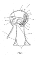
- Fig. 1 shows a sectional view of an embodiment of the peppercorn crusher 1 of the invention.
- Said peppercorn crusher 1 comprises a main body 2 and a handle 3 pivotally mounted on said main body.
- Said main body 2 consists of two identical halves of body, which are fixed together by means of fasteners such as screws etc.
- the figure only shows one half of the body, in which the inner machine parts of said peppercorn crusher are mainly installed.
- Handle 3 has a cylindrical pin 4 passing through its upper end, and the two ends of said cylindrical pin are accommodated in the appointed position of main body 2 (not shown in figure), so that handle 3 is pivotally fixed on main body.
- a spring bow 5 is provided on handle 3, and said spring bow could make handle 3 restoring to its initial position after being pulled toward main body 2.
- a top cover 6 capable to be swung up. With thumb pressing on the stuck-up part of tail end of said top cover, said top cover will swing up and peppercorn to be crushed could be filled into inner chamber of crusher.
- a hollow cylinder At the middle of upper half part of main body 2 is provided a hollow cylinder, the peripheral of which could just sleeved on a spring (not shown), and in the hollow portion of said cylinder is inserted a cylindrical shaft 8, used for mounting of pinion 9 and big gear 10.
- the two ends of said cylindrical shaft are accommodated in appointed position (not shown) of main body 2, so that pinion 9 and big gear 10 could be rotationally fixed in suitable position.
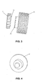
- pinion 9 has two end faces, in which one is flat and smooth, and the other face has a plurality (4 in said embodiment) of protruding teeth (not shown) with 45° inclined side surface.
- cylindrical pin is passed through central hole of pinion, and at this time the face with protruded teeth must be set upwards, while the other smooth face is abut to the spring sleeved on the peripheral of hollow cylinder 7, so that said pinion is pressed against the spring.
- Bakelite plate 11 with semi- circular wall is to be installed.
- a plurality (3 in said embodiment) of protruded portions which could be inserted into corresponding accommodating holes (not shown) in main body 2.
- spring bow 5 of handle 3 would press against semi-circular wall of Bakelite plate 11, and handle 3 would get off in a direction leaving main body 2 due to outward pushing force of spring bow 5.
- a curved piece 12 which would abut to outer wall of main body 2, when handle 3 is pushed to a certain position out of main body 2 due to bow 5.
- One end face of said big gear 10 is flat and smooth, and on other end face of gear 10 is provided a cylindrical portion, on which is arranged full of protruded teeth with 450 (not limited to 45° )inclined side surface.
- cylindrical portion must be downward, so that protruded teeth of said cylindrical portion would be engaged with protruded teeth of pinion 9.
- an arc-shaped crushing plate 14 with serrations and a fineness control mechanism As shown Fig. 6, said mechanism is constituted of fineness control plate 15 for control of fineness of crushed peppercorn and a knob 16 for adjustment of control plate.
- a recess 17 which accommodates the head of knob 16 for turning operation of user.
- At one end of crushing plate 14 is disposed integrally two cylindrical pins 14a, which are accommodated in predetermined holes in main body 2, so that crushing plate could pivotally fixed at suitable position.
- semi-circular protrusion 14b On the back of said crushing plate is provided semi-circular protrusion 14b. The front face (with serrations) of said crushing plate 14 presses on big gear 10 to crush peppercorn.
- Control plate 15 essentially shows as a wide "V" shape, at upper end of which is provided a elliptic hole (not shown), and at lower end of which is provided a 45° inclined protruded portion 15b, engaging the semi-circular protrusion 14b at back of crushing plate.
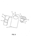
- the configuration of knob 16 is such that near its end is provided a cam-like Bakelite disc 16a, function of which is to limit the rotation of knob by user to 5-180° range by making said cam-like Bakelite piece abut on inner wall of main body, so as to prevent excessive turning of knob.
- cylindrical body 16b Joined together with Bakelite piece 16a is cylindrical body 16b, which is smaller than elliptic hole 15a in control plate 15.
- an eccentric shaft 16c At top of said cylindrical body 16b further disposed an eccentric shaft 16c, which is positioned offset to cylindrical body 16b. Cylindrical body 16b is inserted into elliptic hole 15a, and eccentric shaft 16c is installed at appointed position in main body 2.
- eccentric shaft 16c On account of eccentric shaft 16c is offset to one side, when knob 16 is turned, said eccentric shaft would drive the cylindrical body 16b inserted in the elliptic hole 15a of control plate 15 to rotate along elliptic path, and cylindrical body 16b could move close to either of the upper and lower ends of elliptic hole 15a, so that control plate 15 is made to ascend or descend.
- cylindrical body 16b inserted in the elliptic hole 15a of control plate 15 would pull control plate 15 upward to upper end of elliptic hole 15a.
- control plate 15 Since control plate is pulled upward, 45° inclined protruded portion 15b at lower end of control plate 15 would press against semi-circular protrusion 14b positioned at back of crushing plate 14, so as to push crushing plate coming nearer to big gear making the gap between crushing plate 14 and big gear 10 becomes smaller, and peppercorn would be crushed finer. Contrarily, when knob 16 is turned in reverse direction, cylindrical body 16b would pull control plate 15 downward to lower end of elliptic hole 15a, i.e. pushing control plate 15 downward, so that protruded portion 15b would no more press against semi-circular protrusion 14b at back of crushing plate 14, and the gap between crushing plate 14 and big gear 10 becomes larger, pressure received by peppercorn would be smaller, and peppercorn would not be crushed very fine.
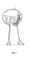
- said sector-shaped gear 13 would drive pinion 9 engaged with it to rotate clockwise, and owing to protruded teeth on pinion is engaged each other with protruded teeth on cylindrical part of big gear, the pinion could drive big gear to rotate also in clockwise direction, and peppercorn within the gap would be crushed, with the crushed peppercorn falling out through passage 19.
- handle would restore to its original position through action of spring bow 5, and at the same time said handle would drive sector-shaped gear 13 return clockwise to its original position. Under driving action of sector-shaped gear, pinion 9 would also return counter-clockwise to its original position.
Abstract
Description
- The invention relates to a crusher, in particular to a peppercorn crusher (pepper mill).
- At present the construction of peppercorn crusher in application appears in the form of a long cylinder, usually consisted of a cylindrical body and a top cover. During operation, the user must hold the cylindrical body with one hand, and turn the cover in 360° with another hand pressing and wresting, so as to crush the peppercorn by a crushing plate positioned under the top cover. Although such design was applied in the market for a period of time, but such peppercorn crusher has following apparent drawbacks:
- 1. Both hands are required at the same time to cooperate for manipulation, inconvenient in application and especially not applicable for the crippled.
- 2. Greater strength is needed to press and wrist the top cover, hence it is not suitable for weak people.
- 3. Fineness of crushed peppercorn is decided by the strength exerted by hand on the top cover, and it depends on the feeling of hand. Thus it is often impossible to obtain the crushed peppercorn with required fineness, and fineness of crushed peppercorn will be uneven in the same operation.
-
- In view of above said problems, the object of the invention is to provide a peppercorn crusher, which can be operated easily with single hand and control fineness of crushed peppercorn.
- To achieve the above object, the invention model provides a peppercorn crusher, comprising a main body, a top cover disposed on the top of main body and a crushing plate, characterized in that said peppercorn crusher further comprises a handle pivotally mounted on main body. On the handle is disposed a spring bow and above the handle a curved piece is provided. Within the main body, gear driving mechanism and fineness control mechanism are provided, wherein the said gear driving mechanism cooperate with crushing plate, and the said fineness control mechanism is linked with crushing plate. Within the main body also is disposed a Bakelite plate with semi-circular wall, and the spring bow presses on the semi-circular wall of Bakelite plate.
- Preferably gear-driving mechanism consists of driving gear, pinion and big gear. Among them, driving gear is connected to shaft of handle, pinion and big gear are mounted coaxially, driving gear is engaged with pinion, and the pinion is engaged with big gear. Big gear works in cooperation with crushing plate. Preferably, the pinion is engaged with big gear in one rotational direction.
- Moreover, on the back of crushing plate is preferably provided with a protrusion. Fineness control mechanism consists of control plate and knob, wherein head of knob is embedded in the main body and at position adjacent to its end is disposed a cam-shaped Bakelite plate. For said knob is also provided a cylinder joined with Bakelite plate and an eccentric shaft mounted on the cylinder with offset. At one end of control plate is provided an elliptic hole and at other end is provided a protruded portion, which engages the protrusion provided on the back of crushing plate. The cylinder of knob is passed into the elliptic hole of control plate, and the eccentric shaft is mounted in the appointed position on main body.
- Comparing with current technique, on account of the unique construction of the peppercorn crusher of the invention, in application of above said peppercorn crusher the user could operate with one hand to crush peppercorn. Moreover, in application of the invention the entire crushing process is driven by means of gear-driving mechanism, therefore user could easily crush peppercorn at expense of very little strength. On the other hand, gear-driving mechanism and crushing plate as a whole could be preassembled within a case, which is then placed into main body, so that it can be adapted to various shapes of body. In addition, a fineness control mechanism is provided in the the invention, and hence fineness of crushed peppercorn could be controlled. In general, the peppercorn crusher of the invention is not only convenient in application, but also timesaving and laborsaving.
- With reference to description of the following drawings of preferred embodiment the invention would be better understood:
- Fig. 1 is a sectional view of a preferred embodiment of the peppercorn crusher of the invention;
- Fig. 2 is a sectional view of the preferred embodiment in which the handle is pulled toward main body;
- Fig. 3 is a perspective view of pinion and big gear;
- Fig. 4 is a perspective view of knob for adjustment of control plate;
- Fig. 5 is a schematic installation view of handle and Bakelite plate;
- Fig. 6 is an exploded schematic view of crushing plate and fineness control mechanism.
-
- Firstly, Fig. 1 shows a sectional view of an embodiment of the
peppercorn crusher 1 of the invention. Saidpeppercorn crusher 1 comprises amain body 2 and ahandle 3 pivotally mounted on said main body. Saidmain body 2 consists of two identical halves of body, which are fixed together by means of fasteners such as screws etc. For the sake of clarity, the figure only shows one half of the body, in which the inner machine parts of said peppercorn crusher are mainly installed. In said peppercorn crusher at same time has mountingposition 2a for installation of these fasteners.Handle 3 has acylindrical pin 4 passing through its upper end, and the two ends of said cylindrical pin are accommodated in the appointed position of main body 2 (not shown in figure), so thathandle 3 is pivotally fixed on main body. In addition, aspring bow 5 is provided onhandle 3, and said spring bow could makehandle 3 restoring to its initial position after being pulled towardmain body 2. - On the top of
main body 2 is provided atop cover 6 capable to be swung up. With thumb pressing on the stuck-up part of tail end of said top cover, said top cover will swing up and peppercorn to be crushed could be filled into inner chamber of crusher. At the middle of upper half part ofmain body 2 is provided a hollow cylinder, the peripheral of which could just sleeved on a spring (not shown), and in the hollow portion of said cylinder is inserted acylindrical shaft 8, used for mounting ofpinion 9 andbig gear 10. The two ends of said cylindrical shaft are accommodated in appointed position (not shown) ofmain body 2, so thatpinion 9 andbig gear 10 could be rotationally fixed in suitable position. - As shown Fig. 3,
pinion 9 has two end faces, in which one is flat and smooth, and the other face has a plurality (4 in said embodiment) of protruding teeth (not shown) with 45° inclined side surface. During installation of pinion, cylindrical pin is passed through central hole of pinion, and at this time the face with protruded teeth must be set upwards, while the other smooth face is abut to the spring sleeved on the peripheral ofhollow cylinder 7, so that said pinion is pressed against the spring. As shown in Fig. 5, after installation ofpinion 9, Bakeliteplate 11 with semi- circular wall is to be installed. On the bottom of said Bakelite plate is provided a plurality (3 in said embodiment) of protruded portions, which could be inserted into corresponding accommodating holes (not shown) inmain body 2. After installation of Bakelite plate is completed,spring bow 5 ofhandle 3 would press against semi-circular wall of Bakeliteplate 11, andhandle 3 would get off in a direction leavingmain body 2 due to outward pushing force ofspring bow 5. In order to prevent the handle pushed out of original position, above handle is provided acurved piece 12, which would abut to outer wall ofmain body 2, whenhandle 3 is pushed to a certain position out ofmain body 2 due tobow 5. One end face of saidbig gear 10 is flat and smooth, and on other end face ofgear 10 is provided a cylindrical portion, on which is arranged full of protruded teeth with 450 (not limited to 45° )inclined side surface. During installation ofbig gear 10, cylindrical portion must be downward, so that protruded teeth of said cylindrical portion would be engaged with protruded teeth ofpinion 9. - On account of particular matching structure of cylindrical portion of big gear and protruding teeth of
pinion 9, the two matching parts could only be engaged in one direction. That is to say, when pinion rotates clockwise to drive big gear, protruding teeth of cylindrical portion of big gear and protruding teeth ofpinion 9 engages with each other, so that pinion can drive the big gear to rotate clockwise. But whenpinion 9 rotates counter-clockwise, protruding teeth ofpinion 9 no longer engages protruding teeth of cylindrical portion of big gear, but slips over the inclined sides of protruding teeth, and the big gear would not rotate with the counter-clockwise rotation of pinion and keeps on stationary. - On the
cylindrical pin 4 ofhandle 3 is also asector gear 13, which engages withpinion 9. When user pullshandle 3 to main body, saidsector gear 13 would swing counter-clockwise with the pivoting ofhandle 3 to drive thepinion 9 rotating clockwise, and said pinion in turn drives big gear to rotate clockwise. Hence these three gears constitute gear-driving mechanism of the invention. In view of the invention utilizes two sets of gearing to drive entire crushing process, users can crush peppercorn without expense of great strength. - In addition, in the
main body 2 is provided also an arc-shaped crushingplate 14 with serrations and a fineness control mechanism. As shown Fig. 6, said mechanism is constituted offineness control plate 15 for control of fineness of crushed peppercorn and aknob 16 for adjustment of control plate. Inmain body 2 is provided arecess 17, which accommodates the head ofknob 16 for turning operation of user. At one end of crushingplate 14 is disposed integrally two cylindrical pins 14a, which are accommodated in predetermined holes inmain body 2, so that crushing plate could pivotally fixed at suitable position. Moreover, on the back of said crushing plate is providedsemi-circular protrusion 14b. The front face (with serrations) of said crushingplate 14 presses onbig gear 10 to crush peppercorn.Control plate 15 essentially shows as a wide "V" shape, at upper end of which is provided a elliptic hole (not shown), and at lower end of which is provided a 45° inclined protruded portion 15b, engaging thesemi-circular protrusion 14b at back of crushing plate. As shown in Fig. 4, the configuration ofknob 16 is such that near its end is provided a cam-like Bakelite disc 16a, function of which is to limit the rotation of knob by user to 5-180° range by making said cam-like Bakelite piece abut on inner wall of main body, so as to prevent excessive turning of knob. Joined together with Bakelite piece 16a is cylindrical body 16b, which is smaller than elliptic hole 15a incontrol plate 15. At top of said cylindrical body 16b further disposed aneccentric shaft 16c, which is positioned offset to cylindrical body 16b. Cylindrical body 16b is inserted into elliptic hole 15a, andeccentric shaft 16c is installed at appointed position inmain body 2. - On account of
eccentric shaft 16c is offset to one side, whenknob 16 is turned, said eccentric shaft would drive the cylindrical body 16b inserted in the elliptic hole 15a ofcontrol plate 15 to rotate along elliptic path, and cylindrical body 16b could move close to either of the upper and lower ends of elliptic hole 15a, so thatcontrol plate 15 is made to ascend or descend. Concretely speaking, whenknob 16 is turned upward, cylindrical body 16b inserted in the elliptic hole 15a ofcontrol plate 15 would pullcontrol plate 15 upward to upper end of elliptic hole 15a. Since control plate is pulled upward, 45° inclined protruded portion 15b at lower end ofcontrol plate 15 would press againstsemi-circular protrusion 14b positioned at back of crushingplate 14, so as to push crushing plate coming nearer to big gear making the gap between crushingplate 14 andbig gear 10 becomes smaller, and peppercorn would be crushed finer. Contrarily, whenknob 16 is turned in reverse direction, cylindrical body 16b would pullcontrol plate 15 downward to lower end of elliptic hole 15a, i.e. pushingcontrol plate 15 downward, so that protruded portion 15b would no more press againstsemi-circular protrusion 14b at back of crushingplate 14, and the gap between crushingplate 14 andbig gear 10 becomes larger, pressure received by peppercorn would be smaller, and peppercorn would not be crushed very fine. - After understanding the construction of entire peppercorn crusher, the working principle of the peppercorn crusher of the invention would be described as follows. During application, user holds the peppercorn crusher with on one hand, and presses on the stuck-up part of tail end of
top cover 6 with the thumb at first to swing up said top cover upward, and peppercorn to be crushed could be filled into inner chamber of crusher. Then peppercorn would fall into the gap between crushingplate 14 andbig gear 10 throughopening 18. User can set required fineness of crushed peppercorn beforehand by turning ofknob 16. When user pulls handle toward main body manually, as shown in Fig. 2, clockwise pivotal rotation ofhandle 3 would drive sector-shapedgear 13 linked to handle to rotate counter-clockwise. Thereupon, said sector-shapedgear 13 would drivepinion 9 engaged with it to rotate clockwise, and owing to protruded teeth on pinion is engaged each other with protruded teeth on cylindrical part of big gear, the pinion could drive big gear to rotate also in clockwise direction, and peppercorn within the gap would be crushed, with the crushed peppercorn falling out throughpassage 19. Once the user leaves go of handle, as mentioned above, handle would restore to its original position through action ofspring bow 5, and at the same time said handle would drive sector-shapedgear 13 return clockwise to its original position. Under driving action of sector-shaped gear,pinion 9 would also return counter-clockwise to its original position. But as mentioned before, at that time protruded teeth onpinion 9 no longer are engaged with protruded teeth on cylindrical part ofbig gear 10, the teeth slips on the inclined sides of protruded teeth ofbig gear 10. Hencebig gear 10 would not rotate with counter-clockwise rotation of pinion, but keeps stationary, so that continuity and degree of pressure of crushing process is guaranteed. - Although the object, features of construction and effect of the invention are concretely described through a preferred embodiment in above, but a person skilled in the art would recognize that above embodiment is used only for description but not for limitation of the invention. As far as spirit and essentials of the invention are not offended, various modifications of above said embodiment are within the scope of claims of the invention.
Claims (9)
- A peppercorn crusher, comprising a main body, a top cover disposed on top of said main body and a crushing plate, characterized in that:said peppercorn crusher further comprises a handle pivotally mounted on main body, on said handle is disposed a spring bow and above the handle a curved piece is provided;within said main body, gear driving mechanism and fineness control mechanism are provided, wherein the said gear driving mechanism cooperate with crushing plate, and the said fineness control mechanism is linked with said crushing plate;within said main body also is disposed a Bakelite plate with semi-circular wall, and said spring bow presses on the semi-circular1 wall of said Bakelite plate.
- The peppercorn crusher according to Claim 1, characterized in that said gear-driving mechanism consists of driving gear, pinion and big gear, wherein said driving gear is connected to cylindrical shaft of said handle; said pinion and big gear are mounted coaxially, said driving gear is engaged with said pinion, and said pinion is engaged with said big gear; said big gear works in cooperation with crushing plate.
- The peppercorn crusher according to Claim 2, characterized in that at the middle of upper half part of main body is provided a hollow cylinder, the peripheral of which is sleeved on a spring, in the hollow portion of said cylinder is inserted a cylindrical shaft, said pinion and big gear are successively mounted on said cylindrical shaft, said pinion is pressed against said spring.
- The peppercorn crusher according to Claim 2, characterized in that on one end face of said pinion are provided a plurality of protruded teeth, and on one end face of said big gear are provided protruded teeth, said protruded teeth of former are engaged with said protruded teeth of latter only in one direction.
- The peppercorn crusher according to Claim 1 or 2, characterized in that at back of said crushing plate is provided a protrusion; said fineness control mechanism comprises control plate and knob; wherein head of said knob is embedded in the main body and at position adjacent to its end is disposed a cam-shaped Bakelite plate, for said knob is also provided a cylinder joined with Bakelite plate and an eccentric shaft mounted on the cylinder with offset; at one end of said control plate is provided an elliptic hole and at other end is provided a protruded portion, which engages the protrusion provided on the back of said crushing plate, said cylinder of knob is passed into the elliptic hole of said control plate, and said eccentric shaft is mounted in the appointed position on main body.
- The peppercorn crusher according to Claim 1, characterized in that said top cover has a tail end with stuck-up part and can be swung up.
- The peppercorn crusher according to Claim 1, characterized in that said main body consists of two identical halves of body, which are fixed together by means of fasteners.
- The peppercorn crusher according to Claim 1, characterized in that on the bottom of said Bakelite plate is provided a plurality of protruded portions, which could be inserted into corresponding accommodating holes in main body.
- The peppercorn crusher according to Claim 2, characterized in that said driving gear is sector-shaped.
Applications Claiming Priority (2)
| Application Number | Priority Date | Filing Date | Title |
|---|---|---|---|
| CN01233474 | 2001-08-16 | ||
| CN01233474.XU CN2496372Y (en) | 2001-08-16 | 2001-08-16 | Black pepper bruiser |
Publications (2)
| Publication Number | Publication Date |
|---|---|
| EP1285619A1 true EP1285619A1 (en) | 2003-02-26 |
| EP1285619B1 EP1285619B1 (en) | 2006-02-15 |
Family
ID=4703198
Family Applications (1)
| Application Number | Title | Priority Date | Filing Date |
|---|---|---|---|
| EP02015134A Expired - Lifetime EP1285619B1 (en) | 2001-08-16 | 2002-07-06 | Peppercorn crusher |
Country Status (9)
| Country | Link |
|---|---|
| US (1) | US6854675B2 (en) |
| EP (1) | EP1285619B1 (en) |
| JP (1) | JP3090662U (en) |
| CN (1) | CN2496372Y (en) |
| AU (1) | AU2002300502B2 (en) |
| CA (1) | CA2390980C (en) |
| DE (1) | DE60209168T2 (en) |
| HK (1) | HK1043498A2 (en) |
| ZA (1) | ZA200206403B (en) |
Cited By (3)
| Publication number | Priority date | Publication date | Assignee | Title |
|---|---|---|---|---|
| EP1880648A1 (en) | 2006-07-21 | 2008-01-23 | Kwok Kuen So | Food cutting device |
| WO2010007113A2 (en) * | 2008-07-18 | 2010-01-21 | Product Works Limited | Adjustable condiment grinder |
| EP2305083A1 (en) * | 2008-07-04 | 2011-04-06 | Yan Kwong Wong | Single-handed vertical solid flavoring grinder |
Families Citing this family (10)
| Publication number | Priority date | Publication date | Assignee | Title |
|---|---|---|---|---|
| US7404527B2 (en) * | 2004-05-21 | 2008-07-29 | Vita-Mix Corporation | Safety shield for an ice shaving machine |
| EP1940273B1 (en) * | 2005-10-19 | 2010-03-24 | Koninklijke Philips Electronics N.V. | Device for chopping food, in particular pieces of ice |
| US7744026B2 (en) * | 2006-05-05 | 2010-06-29 | Helen Of Troy Limited | Food mill including a removable blade assembly |
| WO2009047590A1 (en) | 2007-10-12 | 2009-04-16 | Bich Francois | Grinding system, grinding mill for such grinding system and reload cartridge for such grinding system. |
| US8272588B2 (en) * | 2009-10-30 | 2012-09-25 | Wki Holding Company, Inc. | Rotary mandolin with retractable blade cover |
| US10378807B2 (en) | 2012-03-07 | 2019-08-13 | Snowie LLC | Block ice shaver with tension arm and shaping device |
| CN102640714B (en) * | 2012-05-16 | 2013-12-25 | 蚌埠依爱电子科技有限责任公司 | Width regulating structure for feeding disc feeding windows |
| USD745315S1 (en) * | 2014-03-24 | 2015-12-15 | David Perkins | Hand dough mixer |
| AU201614049S (en) * | 2016-05-30 | 2016-08-01 | Zhejiang Shengli Plastic Co Ltd | Multi-functional vegetable processor |
| USD833806S1 (en) * | 2017-04-21 | 2018-11-20 | Shuangma Plastic Manufacturing Inc. | Food processor |
Citations (5)
| Publication number | Priority date | Publication date | Assignee | Title |
|---|---|---|---|---|
| US1481632A (en) * | 1921-03-30 | 1924-01-22 | John W Tatum | Milling mechanism |
| CH225319A (en) * | 1942-12-26 | 1943-01-31 | L Etang Marc Matthey De | Table salt mill. |
| US4374574A (en) * | 1980-11-03 | 1983-02-22 | Tom David | Condiment grinder-dispenser |
| WO1984000484A1 (en) * | 1982-07-29 | 1984-02-16 | John Cas Czelen | Condiment grinder |
| US5730374A (en) * | 1996-11-25 | 1998-03-24 | Yienn Lih Enterprise Co., Ltd. | Pepper grinding tool |
Family Cites Families (10)
| Publication number | Priority date | Publication date | Assignee | Title |
|---|---|---|---|---|
| US1429348A (en) * | 1922-04-17 | 1922-09-19 | Human Edwin | Vegetable cutter |
| US3602441A (en) * | 1970-02-20 | 1971-08-31 | Gen Electric | Combination ice cube and crushed ice dispenser |
| US4576016A (en) * | 1984-01-13 | 1986-03-18 | King Seeley Thermos Co. | Ice making apparatus |
| JPS6149275U (en) * | 1984-09-05 | 1986-04-02 | ||
| CN1057899A (en) | 1990-07-03 | 1992-01-15 | 陈水谦 | Multifunction juice ice shavings machine |
| JPH079334B2 (en) | 1991-06-24 | 1995-02-01 | 徹 平野 | Ice rake |
| US5273219A (en) * | 1993-01-11 | 1993-12-28 | White Consolidated Industries, Inc. | Ice dispenser |
| JP2978728B2 (en) | 1994-12-05 | 1999-11-15 | 象印マホービン株式会社 | Ice shaver |
| US5513810A (en) * | 1995-05-17 | 1996-05-07 | Shing-Pun Enterprise Co., Ltd. | Thickness adjuster for an ice shaver |
| CN2263324Y (en) | 1996-06-12 | 1997-09-24 | 吴玉斌 | Dual-purpose ice-shaving machine |
-
2001
- 2001-08-16 CN CN01233474.XU patent/CN2496372Y/en not_active Expired - Lifetime
-
2002
- 2002-05-14 HK HK02103634A patent/HK1043498A2/en not_active IP Right Cessation
- 2002-06-12 JP JP2002003526U patent/JP3090662U/en not_active Expired - Lifetime
- 2002-06-19 CA CA002390980A patent/CA2390980C/en not_active Expired - Fee Related
- 2002-07-06 DE DE60209168T patent/DE60209168T2/en not_active Expired - Lifetime
- 2002-07-06 EP EP02015134A patent/EP1285619B1/en not_active Expired - Lifetime
- 2002-08-12 AU AU2002300502A patent/AU2002300502B2/en not_active Ceased
- 2002-08-12 ZA ZA200206403A patent/ZA200206403B/en unknown
- 2002-08-15 US US10/219,138 patent/US6854675B2/en not_active Expired - Fee Related
Patent Citations (5)
| Publication number | Priority date | Publication date | Assignee | Title |
|---|---|---|---|---|
| US1481632A (en) * | 1921-03-30 | 1924-01-22 | John W Tatum | Milling mechanism |
| CH225319A (en) * | 1942-12-26 | 1943-01-31 | L Etang Marc Matthey De | Table salt mill. |
| US4374574A (en) * | 1980-11-03 | 1983-02-22 | Tom David | Condiment grinder-dispenser |
| WO1984000484A1 (en) * | 1982-07-29 | 1984-02-16 | John Cas Czelen | Condiment grinder |
| US5730374A (en) * | 1996-11-25 | 1998-03-24 | Yienn Lih Enterprise Co., Ltd. | Pepper grinding tool |
Cited By (5)
| Publication number | Priority date | Publication date | Assignee | Title |
|---|---|---|---|---|
| EP1880648A1 (en) | 2006-07-21 | 2008-01-23 | Kwok Kuen So | Food cutting device |
| EP2305083A1 (en) * | 2008-07-04 | 2011-04-06 | Yan Kwong Wong | Single-handed vertical solid flavoring grinder |
| EP2305083A4 (en) * | 2008-07-04 | 2012-03-28 | Yan Kwong Wong | Single-handed vertical solid flavoring grinder |
| WO2010007113A2 (en) * | 2008-07-18 | 2010-01-21 | Product Works Limited | Adjustable condiment grinder |
| WO2010007113A3 (en) * | 2008-07-18 | 2010-05-27 | Product Works Limited | Adjustable condiment grinder |
Also Published As
| Publication number | Publication date |
|---|---|
| CN2496372Y (en) | 2002-06-26 |
| EP1285619B1 (en) | 2006-02-15 |
| AU2002300502B2 (en) | 2007-05-31 |
| ZA200206403B (en) | 2003-04-10 |
| DE60209168T2 (en) | 2006-10-19 |
| CA2390980A1 (en) | 2003-02-16 |
| DE60209168D1 (en) | 2006-04-20 |
| US6854675B2 (en) | 2005-02-15 |
| HK1043498A2 (en) | 2002-09-06 |
| US20030034409A1 (en) | 2003-02-20 |
| CA2390980C (en) | 2008-11-18 |
| JP3090662U (en) | 2002-12-20 |
Similar Documents
| Publication | Publication Date | Title |
|---|---|---|
| EP1285619B1 (en) | Peppercorn crusher | |
| US6568843B1 (en) | Safety device for a blender | |
| US4582265A (en) | Garlic crusher and/or mincer | |
| US7430958B2 (en) | Double blade peeling device for vegetables and fruits | |
| US5331741A (en) | Lever-actuated folding knife | |
| US7380737B2 (en) | Electric seasoning mill | |
| US6616076B2 (en) | Spice crusher | |
| US7040561B2 (en) | Spice grinder | |
| JPH06169740A (en) | Juicer | |
| EP0503931B1 (en) | Can opener | |
| EP1839545B1 (en) | Electric seasoning mill | |
| JP2004508080A (en) | Multi-chamber seasoning grinder | |
| KR100524658B1 (en) | Coupling structure of multi using juice extractor | |
| US7416143B1 (en) | Tablet crusher | |
| US7823819B1 (en) | Pill crushing device and its associated method of operation | |
| TWI269647B (en) | Electric seasoning mill | |
| NL1044383B1 (en) | Handle and closing device provided with such a handle | |
| JP4200313B2 (en) | Grinder | |
| JP3073753U (en) | Manual shredder | |
| CN220442533U (en) | Manual coffee bean grinder | |
| CN214629523U (en) | Multifunctional noodle processing device | |
| JPS6220202Y2 (en) | ||
| KR200269007Y1 (en) | Polishing for juicer | |
| KR950002976Y1 (en) | Juicer | |
| JPH038931Y2 (en) |
Legal Events
| Date | Code | Title | Description |
|---|---|---|---|
| PUAI | Public reference made under article 153(3) epc to a published international application that has entered the european phase |
Free format text: ORIGINAL CODE: 0009012 |
|
| AK | Designated contracting states |
Kind code of ref document: A1 Designated state(s): AT BE BG CH CY CZ DE DK EE ES FI FR GB GR IE IT LI LU MC NL PT SE SK TR |
|
| AX | Request for extension of the european patent |
Extension state: AL LT LV MK RO SI |
|
| 17P | Request for examination filed |
Effective date: 20030731 |
|
| AKX | Designation fees paid |
Designated state(s): DE FR GB IT |
|
| 17Q | First examination report despatched |
Effective date: 20050225 |
|
| GRAP | Despatch of communication of intention to grant a patent |
Free format text: ORIGINAL CODE: EPIDOSNIGR1 |
|
| GRAS | Grant fee paid |
Free format text: ORIGINAL CODE: EPIDOSNIGR3 |
|
| GRAA | (expected) grant |
Free format text: ORIGINAL CODE: 0009210 |
|
| AK | Designated contracting states |
Kind code of ref document: B1 Designated state(s): DE FR GB IT |
|
| REG | Reference to a national code |
Ref country code: GB Ref legal event code: FG4D |
|
| REF | Corresponds to: |
Ref document number: 60209168 Country of ref document: DE Date of ref document: 20060420 Kind code of ref document: P |
|
| ET | Fr: translation filed | ||
| PLBE | No opposition filed within time limit |
Free format text: ORIGINAL CODE: 0009261 |
|
| STAA | Information on the status of an ep patent application or granted ep patent |
Free format text: STATUS: NO OPPOSITION FILED WITHIN TIME LIMIT |
|
| 26N | No opposition filed |
Effective date: 20061116 |
|
| REG | Reference to a national code |
Ref country code: FR Ref legal event code: PLFP Year of fee payment: 15 |
|
| REG | Reference to a national code |
Ref country code: FR Ref legal event code: PLFP Year of fee payment: 16 |
|
| PGFP | Annual fee paid to national office [announced via postgrant information from national office to epo] |
Ref country code: GB Payment date: 20170822 Year of fee payment: 16 Ref country code: DE Payment date: 20170905 Year of fee payment: 16 Ref country code: IT Payment date: 20170727 Year of fee payment: 16 Ref country code: FR Payment date: 20170731 Year of fee payment: 16 |
|
| REG | Reference to a national code |
Ref country code: DE Ref legal event code: R119 Ref document number: 60209168 Country of ref document: DE |
|
| GBPC | Gb: european patent ceased through non-payment of renewal fee |
Effective date: 20180706 |
|
| PG25 | Lapsed in a contracting state [announced via postgrant information from national office to epo] |
Ref country code: FR Free format text: LAPSE BECAUSE OF NON-PAYMENT OF DUE FEES Effective date: 20180731 Ref country code: GB Free format text: LAPSE BECAUSE OF NON-PAYMENT OF DUE FEES Effective date: 20180706 Ref country code: DE Free format text: LAPSE BECAUSE OF NON-PAYMENT OF DUE FEES Effective date: 20190201 |
|
| PG25 | Lapsed in a contracting state [announced via postgrant information from national office to epo] |
Ref country code: IT Free format text: LAPSE BECAUSE OF NON-PAYMENT OF DUE FEES Effective date: 20180706 |