EP1285557B1 - Improved apparatus and method for positioning implantable hearing aid device - Google Patents
Improved apparatus and method for positioning implantable hearing aid device Download PDFInfo
- Publication number
- EP1285557B1 EP1285557B1 EP01922459A EP01922459A EP1285557B1 EP 1285557 B1 EP1285557 B1 EP 1285557B1 EP 01922459 A EP01922459 A EP 01922459A EP 01922459 A EP01922459 A EP 01922459A EP 1285557 B1 EP1285557 B1 EP 1285557B1
- Authority
- EP
- European Patent Office
- Prior art keywords
- carrier
- recited
- relative
- interconnected
- swivel
- Prior art date
- Legal status (The legal status is an assumption and is not a legal conclusion. Google has not performed a legal analysis and makes no representation as to the accuracy of the status listed.)
- Expired - Lifetime
Links
Images


Classifications
-
- A—HUMAN NECESSITIES
- A61—MEDICAL OR VETERINARY SCIENCE; HYGIENE
- A61B—DIAGNOSIS; SURGERY; IDENTIFICATION
- A61B17/00—Surgical instruments, devices or methods, e.g. tourniquets
- A61B17/34—Trocars; Puncturing needles
- A61B17/3403—Needle locating or guiding means
-
- A—HUMAN NECESSITIES
- A61—MEDICAL OR VETERINARY SCIENCE; HYGIENE
- A61B—DIAGNOSIS; SURGERY; IDENTIFICATION
- A61B90/00—Instruments, implements or accessories specially adapted for surgery or diagnosis and not covered by any of the groups A61B1/00 - A61B50/00, e.g. for luxation treatment or for protecting wound edges
- A61B90/10—Instruments, implements or accessories specially adapted for surgery or diagnosis and not covered by any of the groups A61B1/00 - A61B50/00, e.g. for luxation treatment or for protecting wound edges for stereotaxic surgery, e.g. frame-based stereotaxis
- A61B90/11—Instruments, implements or accessories specially adapted for surgery or diagnosis and not covered by any of the groups A61B1/00 - A61B50/00, e.g. for luxation treatment or for protecting wound edges for stereotaxic surgery, e.g. frame-based stereotaxis with guides for needles or instruments, e.g. arcuate slides or ball joints
-
- H—ELECTRICITY
- H04—ELECTRIC COMMUNICATION TECHNIQUE
- H04R—LOUDSPEAKERS, MICROPHONES, GRAMOPHONE PICK-UPS OR LIKE ACOUSTIC ELECTROMECHANICAL TRANSDUCERS; DEAF-AID SETS; PUBLIC ADDRESS SYSTEMS
- H04R2225/00—Details of deaf aids covered by H04R25/00, not provided for in any of its subgroups
- H04R2225/67—Implantable hearing aids or parts thereof not covered by H04R25/606
Definitions
- the present invention relates to an apparatus and method for supportably positioning an implantable hearing aid actuator within a patient's skull, and more particularly, to a positioning apparatus and method that provides ease-of-installation, range-of-application, actuator loading and depth positioning advantages.
- implantable hearing aid devices include those which utilize implanted electromechanical transducers for stimulation of the ossicular chain and/or oval window (see e. g., U. S. Patent No. 5,702,342 ), and those which utilize implanted excitor coils to electromagnetically stimulate magnets affixed within the middle ear (see e. g., U. S. Patent No. 5,897,486 ).
- implantable hearing aid actuators For purposes hereof, such electromechanical transducers and excitor coils, as well other implanted devices that stimulate the ossicular chain and/or oval window will be collectively referred to as "implantable hearing aid actuators".
- hearing aid devices of the above-noted nature entail supportable positioning of the given implantable actuator within a patient's skull.
- an opening is surgically defined in a patient's skull and the implantable actuator is inserted through the opening for supportable positioning within the mastoid process.
- precise placement and orientation of the implantable actuator can be of paramount importance to achieve best results.
- implantable actuator(s) may supportably disposed for selective in-site positioning in multiple dimensions relative to a skull mounting device. While such arrangements have represented an advance in the art, they often entailed the positioning of a number of separate, hard-to-handle components, thereby adding to the complexity already associated with implant procedures. Additionally, the present inventors believe that further enhanced positioning of implantable actuators is achievable, particularly with respect to the depth profile which can vary significantly from patient to patient.
- US-A-5788711 describes an implantable hearing aid device having a mount for securing to the patient's skull, an axially extendable carrier supporting a sensor device and a ball-and-socket joint comprising a ball sandwiched between a pair of opposed plates, one of which is part of the mount and the other is secured to the first by screws.
- the carrier is secured to the ball and, while the ball is rotatable between the plates, the carrier and the sensor can be pivoted to a desired position and can be locked in that position by clamping the ball between the plates.
- the apparatus includes a carrier device for carrying an implantable hearing aid actuator at a first end, and a swivel device for pivotably supporting the carrier device.
- a carrier device for carrying an implantable hearing aid actuator at a first end
- a swivel device for pivotably supporting the carrier device.
- Such pivotable support allows the first-end of the carrier device to be laterally pivotable in first and second dimensions relative to the swivel device.
- the apparatus further includes a mounting device for mounting the apparatus to a patient's skull, wherein the swivel device is unitary and selectively securable as a single unit to the mounting device.
- the unitary swivel device includes interconnected, opposing first and second holder members with a pivot member (e. g., a rotatable ball) captured between the first and second holder members.
- the pivot member may include an opening for supportably receiving the carrier device, wherein the carrier device is slidably positionable in the opening along a linear continuum of positions in the third dimension.
- pivotable movement of the carrier device will effect corresponding rotation of the pivot member relative to the interconnected first and second holder members.
- the swivel device is provided in a unitary fashion. That is, the swivel device is selectively positionable relative to and otherwise securable to the mounting device as a single unit. Such an arrangement simplifies installation procedures in conjunction with hearing aid implants. Further, to enhance actuator depth positioning, the carrier device and swivel device are preferably adapted to allow the carrier device to be selectively positioned in a third dimension relative to the swivel device.
- first and second holder members may be interconnected to permit a limited range of relative movement therebetween, thereby facilitating selective rotation of the pivot member upon pivotable movement of the carrier device.
- inventive apparatus may further comprise a locking member interconnectable to the mounting device to selectively apply a compressive force to and thereby restrict relative movement between the first and second holder members, wherein a selected angular orientation between the carrier device and the mounting device may be maintained by the locking member.
- the locking member may also be employable to lock-in a selected linear position of the carrier device relative to the swivel device.
- the pivot member may include a plurality of slits extending through an upper portion thereof to define a plurality of separated, upper portions ofthe pivot member.
- the first holder member may comprise an aperture sized for contact positioning about the slitted portion of the pivot member. Consequently, when the locking member is interconnected to the mounting device to apply a compressive force to the first and second holders, such force will effect inward movement of the plurality of separated, upper portions to restrictably engage the carrier device.
- the carrier device may be interconnected to the swivel device in a manner that allows for selective advancement of the carrier device relative to the swivel device, wherein a first degree of actuator depth positioning latitude is provided; and, the carrier device may comprise at least a first carrier member and an interconnected second carrier member having a distal end connectable to an actuator, wherein the second carrier member is selectively advancable relative to the first carrier member to yield a second degree of depth positioning latitude.
- the first and second carrier members may be disposed coaxially and interconnected for selective, telescoping advancement of the second carrier member relative to the first carrier member.
- the first and second carrier members may be threadably interconnected, wherein driven rotation of the first carrier member effects a predetermined degree of linear travel by the second carrier member.
- the swivel device may include an opening for supportably receiving the carrier device, wherein a top end of the first carrier member projects from the swivel device to provide ready access for driven rotation by an accessory tool.
- the carrier device may further include a third carrier member, rotatably interconnected to the first carrier member, for restricting rotational movement of the second carrier member.
- the second carrier member may include a linear slot while the third carrier member includes a projecting retention pin positioned within the slot of the second carrier member.
- a mounting device which includes a cylindrical barrel portion for supportably receiving a swivel device and carrier device interconnected thereto.
- the barrel portion includes a bottom end plate and is internally threaded, wherein the swivel device may be "locked-in" between an externally threaded locking member and the bottom end plate.
- the swivel device may include interconnected, top and bottom plate members with opposing central apertures having beveled edge surfaces for receiving a round pivot member therebetween.
- the pivot member is provided with a central opening therethrough for slidably receiving an outer support member of the carrier device.
- the carrier device further includes an internal shaft member rotatably interconnected at a top end to a top end of the outer support member, and interconnected at a bottom end to a telescoping member.
- a distal end of the telescoping member is interconnected to an electromechanical transducer actuator.
- the entire carrier device may be selectively located at one of a linear continuum of positions relative to the swivel device to provide a first measure of depth positioning control. Further, the carrier device may be pivoted relative to the mounting device to provide for lateral positioning of the electromechanical transducer actuator. When a desired depth and angular orientation of the carrier device is established, such position may be "locked-in” by tightening the locking ring down on the swivel assembly. Then, the telescoping member of the carrier device may be selectively advanced to position the electromechanical transducer actuator in a desired contact position with the ossicular chain (e.g., contact with the incus bone) or oval window.
- the ossicular chain e.g., contact with the incus bone
- an inventive method for positioning an implantable hearing aid actuator includes the steps of attaching a mounting device to a patient's skull and supporting a swivel device on the mounting device, wherein the swivel device pivotably supports a carrier device having an implantable hearing aid actuator interconnected thereto. The method further provides for the positioning of the carrier device so as to locate the implantable hearing aid actuator at a desired location within the patient's skull.
- the supporting step is achieved via the placement of the swivel device as a single unit into a support position on the mounting device.
- this may be achieved by inserting the swivel device as a unit into a barrel portion of the mounting device and supportably engaging a bottom end plate of the barrel portion.
- the positioning step of the inventive method preferably includes the sub-steps of pivoting the carrier device and interconnected implantable hearing aid actuator into a desired angular orientation relative to the mounting device within a patient's skull, and advancing the carrier device relative to the swivel device. Further, in an arrangement where the carrier device includes at least first and second carrier members, the positioning step may further include the sub-step of advancing the second carrier member relative to the first carrier member.
- a desired contact location may be defmed on the ossicular chain (e.g., the incus bone) or oval window within a patient's skull, wherein a probe tip of the electromechanical transducer actuator is brought into gradual contact with the contact location during positioning.
- the inventive method may further provide for advancing the second carrier member relative to the first carrier member so as to provide a predetermined degree of loading by the probe tip on the contact location.
- the mounting apparatus 10 includes a carrier assembly 20, a swivel assembly 40, and a mounting assembly 60. Such assemblies may be readily interconnected and disposed to cooperate in a manner that allows for selective, three-dimensional positioning of an implantable hearing aid actuator, such as exemplary actuator 80, at a desired location within a patient's skull.
- an implantable hearing aid actuator such as exemplary actuator 80
- the exemplary actuator 80 may be supportably connected to a first end 22 of the carrier assembly 20.
- the carrier assembly 20 may be supportably received in an opening 42 provided in the swivel assembly 40 and the assembled carrier assembly20/swivel assembly 40 maybe supportablyinterconnected to a mounting apparatus 62 attached to a patient's skull (e.g. via the insertion of skull attachment devices 70 through aperatures 65 of mounting legs 63 into the skull).
- the interconnection between carrier assembly 20 and swivel assembly 40 provides for pivotable, lateral positioning of the first end 22 of the carrier assembly 20, and of the actuator 80 interconnected thereto.
- carrier device 20 and swivel assembly 40 may be provided so that carrier assembly 20 may be selectively secured along a continuum of positions within the opening 42 of the swivel assembly 40, thereby facilitating advancement/retraction ofthe carrier assembly 20 and interconnected actuator 80, in a depth dimension. Additionally, the carrier assembly 20 may be defined so that its first end 22 may be selectively advanced/retracted in the depth dimension relative to an outer support member 24 thereto.
- swivel assembly 40 may be provided in a unitary, or interconnected, form so that it may be readily positioned about the outer support member 24 of carrier assembly 20, thereby facilitating positioning and interconnection of the swivel assembly 40 within the mounting apparatus 62.
- swivel assembly 40 is configured for mating receipt in a predetermined orientation by a complimentarily configured barrel portion 64 of mounting apparatus 62.
- unitary swivel assembly 40 is sized to supportably rest upon an end plate portion 66 of mounting apparatus 62.
- a locking member 68 positionable within a top end of the barrel 64 of mounting apparatus 62, may be tightened against the top of swivel assembly 40 to "lock-in" the desired linear and angular position of carrier assembly 20.
- swivel assembly 40 includes opposing, top and bottom plate members 44a and 44b, respectively, which are interconnected to capture a rotatable ball member 46 therebetween.
- the top and bottom plate members 44a, 44b include centrally aligned apertures 45a, 45b, with opposing beveled, ring-shaped, edge surfaces 41 a, 41b, wherein the ball member 46 is seated between the beveled surfaces 41a and 41b.
- the rotatable ball member 46 also includes an aperture 47 there through which, together with apertures 45a, 45b, collectively define the opening 42 of swivel assembly 40.
- aperture 47 may be sized to slidably receive the outer support member 24, yet restrain free relative movement therebetween.
- apertures 45a, 45b are sized larger than aperture 47 so as to permit pivotal movement of carrier assembly 20 within a predetermined range of motion.
- swivel assembly 20 may be provided so as to permit carrier assembly 20 to pivot up to 30° about and relative to a center axis passing through the apertures 45a and 45b.
- top and bottom plate members 44a and 44b are interconnected by headed pins 48 which are inserted through apertures 50a and 50b of the top and bottom plate members 44a and 44b, respectively.
- the apertures 50b defined in the bottom plate member 44b are sized for retentive press-fit receipt of the bottom ends of headed pins 48.
- the apertures 50a defined in top plate member 44a are sized relative to the headed pins 48 to permit a small degree of linear travel therebetween (e.g., about 01"), thereby allowing the ball member 46 to rotate relative to the top and bottom plate members 44a and 44b, absent the application of a compressive force on the swivel assembly 40.
- Figs. 2C and 2D illustrate swivel assembly 40 with the top plate member 44a in a "lifted" position and in a "compressed" position, respectively.
- a locking member 68 may be provided to apply a force to the top plate member 44a to lock-in a desired linear and angular disposition of the carrier assembly 20 shown in Fig.1 .
- rotatable ball member 46 includes four slits 52 which extend from aperture 47 through a top portion of the ball member 46 to define four slightly separated upper sections. Of importance, slits 52 extend through only a portion of the rotatable ball member 46. Consequently, and as shown by Fig.
- the beveled surface 41 a of the top plate member 44a will act to apply on inward force about a top end of the ball member 46 so as to urge the four upper sections thereof inwards.
- the inward motion of the top sections of ball member 46 may serve to lock-in a given linear position of the carrier assembly 20 relative to the swivel assembly 40.
- annular surface 41a of the top plate member 44a will act to apply downward forces about the contacted ring portion of ball member 46, thereby serving to lock-in a given rotational orientation of ball member 46 relative to the top and bottom plate members 44a, 44b.
- annular surface 41a of the top plate member 44a will act to apply downward forces about the contacted ring portion of ball member 46, thereby serving to lock-in a given rotational orientation of ball member 46 relative to the top and bottom plate members 44a, 44b.
- the ability to lock-in a given rotational orientation of ball member 46 allows the carrier assembly 20 to be set in a desired angular position.
- the illustrated carrier assembly 20 includes an outer support member 24, an inner shaft member 26 and an extendable, or telescoping, shaft member 28 having a foot-like configuration which defines the first end 22 of the carrier assembly 20.
- inner shaft member 26 is threaded for driven engagement with an internally threaded surface within telescoping support member 28.
- a ring portion 30 is provided at the top end of the internal shaft 26 and is sized for rotatable positioning in a bushing arrangement defined by top and bottom ring members 32a, 32b.
- top and bottom ring members 32a, 32b may be interconnected about their annular peripheries so as to capture the ring portion 30 of the internal shaft member 26, and the adjoined rings 32a, 32b may be secured within a top end 34 of the outer tube member 24.
- Such an arrangement axially fixes internal shaft member 26 relative to the outer support member 24, but allows the internal shaft member 26 to be rotated relative to the outer support member 24, e.g., via driven engagement by an accessory tool with a hex-end 36 provided at the top end of the internal shaft member 26.
- telescoping support member 28 may be provided with an internally threaded surface for threaded engagement with the inner shaft member 26. Further, telescoping support member 28 may include an outer groove 38 extending along the length of the telescoping support member 28. Such groove 38 is provided to co-act with a restraining member 39 projecting from the outer support member 24. More particularly, when outer support member 24 is in a locked position as described above, restraining member 39 acts to restrain telescoping support member 28 from rotation relative to outer support member 24 upon driven rotation of inner shaft 24. As such, upon driven rotation of inner shaft member 26, the telescoping support member 28, and an implantable actuator 80 interconnected to the footed first end 22 thereof, may be selectively advanced/retracted relative to the outer support member 24 and inner shaft member 26.
- an opening 100 in the mastoid process of a patient's skull may be defined by drilling or other appropriate process.
- the opening 100 should be of size sufficient to accommodate insertion of a cylindrical barrel portion 64 of the mounting apparatus 62 therethrough.
- Fig. 1 illustrates a mounting assembly 60 for which skull attachment of the mounting apparatus 62 is achieved via the use of attachment devices 70 inserted through apertures 65 provided in radiating mounting legs 63 at the top end of the mounting apparatus 62.
- the cylindrical barrel portion 64 may be provided with external threads 67 for threaded engagement with a tapped bore portion defined within the opening 100 of a patient's skull.
- various components of the positioning embodiment 10, together with an interconnected actuator 80 maybe positioned through the mounting apparatus 62.
- interconnection of the various components of the positioning assembly 10, as well as interconnection of the positioning assembly 10 to actuator 80 may be completed in conjunction with an implant procedure, or alternatively, may be at least partially completed as part of a production/assembly operation prior to shipment.
- footed first end 22 of telescoping support member 28 of the carrier assembly 20 may be slidably disposed within a channel 88 provided at the top end of actuator 80 a body portion 84, and swivel assembly 40 may be positioned as a unit about the outer support member 24 of the carrier assembly 20.
- the opening 42 defined through swivel assembly 40 may be sized for slidable friction fit with the outside surface of the support member 24 so as to allow for slidable relative positioning between the two, as well as a degree ofretention that restricts swivel assembly 40 from simply sliding off the carrier assembly 20.
- interconnected positioning assembly 10 and actuator 80 In positioning the interconnected positioning assembly 10 and actuator 80 within the mounting apparatus 62, it may be noted that tab-like extensions of the top and bottom plate members 44a, 44b of the swivel assembly 40, as well as rectangular portions of the footed first end 22 and actuator 80, as well as a signal transmission cable 86 comprising actuator 80, may all be aligned relative to a complimentary opening 69 provided along one side of the barrel portion 64 of the mounting apparatus 62.
- the interconnected positioning assembly 10 and actuator 80 may then be linearly advanced through the barrel portion 64 of mounting apparatus 62 until the bottom plate member 44b of swivel assembly 40 supportably engages the bottom end plate 66 of the mounting apparatus 62. Then, the locking ring 68 may be located in the top end of the barrel portion 64, but not yet tightened against swivel assembly 40.
- the positioning apparatus 10 is now disposed for selective positioning of actuator 80.
- an accessory tool 200 may be inserted through an aperture in locking ring 68 to engage the hex-end 36 of the internal shaft member 26 of carrier assembly 20.
- the hearing aid actuator 80 may be selectively advanced/retracted into a preliminarily desired depth position via slidable advancement/retraction ofthe outer support member 24 of the carrier assembly 20 within the opening 42 of the swivel assembly 40.
- the angular orientation of the actuator 80 may be selectively adjusted via use of the accessory tool 200 to effect pivotal movement of the carrier assembly 20 and rotation of ball member 46 relative to the top and bottom plate members 44a, 44b of the swivel assembly 40.
- actuator 80 comprises an electromechanical transducer (e.g. as shown in Figs. 1 , 4 and 5 )
- a probe tip 82 of the actuator 80 may be pivoted into a position where it is directed towards a desired contact location 120 on the incus bone 110.
- a small hole may be defined at the desired contact location 120 on the surface of the incus 110 (e.g., via use of a laser guide arrangement). It should be noted that the contact location maybe defined on other ossicular bones or even perhaps the oval window.
- the locking ring 68 may be further advanced within the barrel portion 64 of the mounting apparatus 60 so as lock in the set angular orientation and depth setting of the carrier assembly 20. Then, to achieve precise positioning of the probe tip 82 a further accessory tool (not shown) may be inserted through the aperture of the mounting/locking ring 68 to natingly engage the hex-end 36 of the internal shaft member 26 of the carrier assembly 20 for driven rotation thereof.
- the threading provided on the internal shaft member 26 and telescoping shaft member 28 may be defined so that, for a given amount of driven rotation of the hex-end 36, a corresponding predetermined desire of linear travel by the first end 22 of the telescoping shaft member 28 will be affected (e.g., 1/4 mm travel for each complete rotation).
- a predetermined degree of loading may be selectively established by driven rotation of hex-end 36 a predetermined number of revolutions.
- the ability to achieve precise positioning, and loading of an actuator 80 relative to the ossicular chain yields enhanced acoustic signal transmission and overall improved hearing aid performance. After positioning of the actuator 80, placement of and connections between other implanted components of a given hearing aid system may be completed prior to system testing and surgical sew-up.
Landscapes
- Health & Medical Sciences (AREA)
- Surgery (AREA)
- Life Sciences & Earth Sciences (AREA)
- Medical Informatics (AREA)
- Nuclear Medicine, Radiotherapy & Molecular Imaging (AREA)
- Engineering & Computer Science (AREA)
- Biomedical Technology (AREA)
- Heart & Thoracic Surgery (AREA)
- Pathology (AREA)
- Molecular Biology (AREA)
- Animal Behavior & Ethology (AREA)
- General Health & Medical Sciences (AREA)
- Public Health (AREA)
- Veterinary Medicine (AREA)
- Prostheses (AREA)
- Control Of Position Or Direction (AREA)
Abstract
Description
- The present invention relates to an apparatus and method for supportably positioning an implantable hearing aid actuator within a patient's skull, and more particularly, to a positioning apparatus and method that provides ease-of-installation, range-of-application, actuator loading and depth positioning advantages.
- Several types of implantable hearing aid devices have been proposed. Principally, such devices include those which utilize implanted electromechanical transducers for stimulation of the ossicular chain and/or oval window (see e. g.,
U. S. Patent No. 5,702,342 ), and those which utilize implanted excitor coils to electromagnetically stimulate magnets affixed within the middle ear (see e. g.,U. S. Patent No. 5,897,486 ). - For purposes hereof, such electromechanical transducers and excitor coils, as well other implanted devices that stimulate the ossicular chain and/or oval window will be collectively referred to as "implantable hearing aid actuators".
- In most instances, hearing aid devices of the above-noted nature entail supportable positioning of the given implantable actuator within a patient's skull. In many procedures, an opening is surgically defined in a patient's skull and the implantable actuator is inserted through the opening for supportable positioning within the mastoid process. In conjunction with such implant procedures, precise placement and orientation of the implantable actuator can be of paramount importance to achieve best results.
- To yield precise positioning a number of arrangements have been proposed, wherein implantable actuator(s) may supportably disposed for selective in-site positioning in multiple dimensions relative to a skull mounting device. While such arrangements have represented an advance in the art, they often entailed the positioning of a number of separate, hard-to-handle components, thereby adding to the complexity already associated with implant procedures. Additionally, the present inventors believe that further enhanced positioning of implantable actuators is achievable, particularly with respect to the depth profile which can vary significantly from patient to patient.
-
US-A-5788711 describes an implantable hearing aid device having a mount for securing to the patient's skull, an axially extendable carrier supporting a sensor device and a ball-and-socket joint comprising a ball sandwiched between a pair of opposed plates, one of which is part of the mount and the other is secured to the first by screws. The carrier is secured to the ball and, while the ball is rotatable between the plates, the carrier and the sensor can be pivoted to a desired position and can be locked in that position by clamping the ball between the plates. - In view of the foregoing, a primary objective of the present invention is to provide an apparatus and method for supportably positioning an implantable hearing actuator at a desired location with enhanced ease-of-installation. Additional objectives are to provide an implantation apparatus and method that yields enhanced accuracy in implantable hearing aid actuator positioning and/or range-of-application advantages. Yet a further objective of the present invention is to provide an apparatus and method that facilitates accurate, contact loading of an electromechanical transducer relative to a patient's ossicle.
- One or more of the above-noted objectives as well as additional advantages are provided in the inventive apparatus as defined in the accompanying claims; the apparatus includes a carrier device for carrying an implantable hearing aid actuator at a first end, and a swivel device for pivotably supporting the carrier device. Such pivotable support allows the first-end of the carrier device to be laterally pivotable in first and second dimensions relative to the swivel device. The apparatus further includes a mounting device for mounting the apparatus to a patient's skull, wherein the swivel device is unitary and selectively securable as a single unit to the mounting device. The unitary swivel device includes interconnected, opposing first and second holder members with a pivot member (e. g., a rotatable ball) captured between the first and second holder members.
- The pivot member may include an opening for supportably receiving the carrier device, wherein the carrier device is slidably positionable in the opening along a linear continuum of positions in the third dimension. As may be appreciated, pivotable movement of the carrier device will effect corresponding rotation of the pivot member relative to the interconnected first and second holder members.
- In one aspect of the present invention the swivel device is provided in a unitary fashion. That is, the swivel device is selectively positionable relative to and otherwise securable to the mounting device as a single unit. Such an arrangement simplifies installation procedures in conjunction with hearing aid implants. Further, to enhance actuator depth positioning, the carrier device and swivel device are preferably adapted to allow the carrier device to be selectively positioned in a third dimension relative to the swivel device.
- In the later regard, the first and second holder members may be interconnected to permit a limited range of relative movement therebetween, thereby facilitating selective rotation of the pivot member upon pivotable movement of the carrier device. Relatedly, the inventive apparatus may further comprise a locking member interconnectable to the mounting device to selectively apply a compressive force to and thereby restrict relative movement between the first and second holder members, wherein a selected angular orientation between the carrier device and the mounting device may be maintained by the locking member.
- Further, the locking member may also be employable to lock-in a selected linear position of the carrier device relative to the swivel device. More particularly, the pivot member may include a plurality of slits extending through an upper portion thereof to define a plurality of separated, upper portions ofthe pivot member. Correspondingly, the first holder member may comprise an aperture sized for contact positioning about the slitted portion of the pivot member. Consequently, when the locking member is interconnected to the mounting device to apply a compressive force to the first and second holders, such force will effect inward movement of the plurality of separated, upper portions to restrictably engage the carrier device.
- In another aspect of the present invention, the carrier device may be interconnected to the swivel device in a manner that allows for selective advancement of the carrier device relative to the swivel device, wherein a first degree of actuator depth positioning latitude is provided; and, the carrier device may comprise at least a first carrier member and an interconnected second carrier member having a distal end connectable to an actuator, wherein the second carrier member is selectively advancable relative to the first carrier member to yield a second degree of depth positioning latitude. Such multiple depth positioning functionality not only facilitates accurate placement of an implantable hearing aid actuator but also facilitates a greater depth positioning range for an increased range of patient applications. In one arrangement, the first and second carrier members may be disposed coaxially and interconnected for selective, telescoping advancement of the second carrier member relative to the first carrier member.
- Preferably, the first and second carrier members may be threadably interconnected, wherein driven rotation of the first carrier member effects a predetermined degree of linear travel by the second carrier member. In this regard, the swivel device may include an opening for supportably receiving the carrier device, wherein a top end of the first carrier member projects from the swivel device to provide ready access for driven rotation by an accessory tool.
- In addition to first and second carrier members, the carrier device may further include a third carrier member, rotatably interconnected to the first carrier member, for restricting rotational movement of the second carrier member. In one arrangement, the second carrier member may include a linear slot while the third carrier member includes a projecting retention pin positioned within the slot of the second carrier member. As such, when the third carrier member is rotationally fixed (e.g., via use of a locking member as noted above) and the first carrier member is rotated, the third carrier member restricts rotation of the second carrier member, thereby causing the second carrier member to telescope away from both of the first and third carrier members.
- In one embodiment, a mounting device is provided which includes a cylindrical barrel portion for supportably receiving a swivel device and carrier device interconnected thereto. The barrel portion includes a bottom end plate and is internally threaded, wherein the swivel device may be "locked-in" between an externally threaded locking member and the bottom end plate. The swivel device may include interconnected, top and bottom plate members with opposing central apertures having beveled edge surfaces for receiving a round pivot member therebetween. The pivot member is provided with a central opening therethrough for slidably receiving an outer support member of the carrier device. The carrier device further includes an internal shaft member rotatably interconnected at a top end to a top end of the outer support member, and interconnected at a bottom end to a telescoping member. In turn, a distal end of the telescoping member is interconnected to an electromechanical transducer actuator.
- The entire carrier device may be selectively located at one of a linear continuum of positions relative to the swivel device to provide a first measure of depth positioning control. Further, the carrier device may be pivoted relative to the mounting device to provide for lateral positioning of the electromechanical transducer actuator. When a desired depth and angular orientation of the carrier device is established, such position may be "locked-in" by tightening the locking ring down on the swivel assembly. Then, the telescoping member of the carrier device may be selectively advanced to position the electromechanical transducer actuator in a desired contact position with the ossicular chain (e.g., contact with the incus bone) or oval window.
- In view of the foregoing, it will apparent that an inventive method for positioning an implantable hearing aid actuator is also provided. The inventive method includes the steps of attaching a mounting device to a patient's skull and supporting a swivel device on the mounting device, wherein the swivel device pivotably supports a carrier device having an implantable hearing aid actuator interconnected thereto. The method further provides for the positioning of the carrier device so as to locate the implantable hearing aid actuator at a desired location within the patient's skull.
- Preferably, the supporting step is achieved via the placement of the swivel device as a single unit into a support position on the mounting device. In one embodiment, this may be achieved by inserting the swivel device as a unit into a barrel portion of the mounting device and supportably engaging a bottom end plate of the barrel portion.
- The positioning step of the inventive method preferably includes the sub-steps of pivoting the carrier device and interconnected implantable hearing aid actuator into a desired angular orientation relative to the mounting device within a patient's skull, and advancing the carrier device relative to the swivel device. Further, in an arrangement where the carrier device includes at least first and second carrier members, the positioning step may further include the sub-step of advancing the second carrier member relative to the first carrier member.
- When an electromechanical transducer actuator is utilized, a desired contact location may be defmed on the ossicular chain (e.g., the incus bone) or oval window within a patient's skull, wherein a probe tip of the electromechanical transducer actuator is brought into gradual contact with the contact location during positioning. In this regard, the inventive method may further provide for advancing the second carrier member relative to the first carrier member so as to provide a predetermined degree of loading by the probe tip on the contact location.
- Numerous additional aspects and advantages ofthe present invention will become apparent to those skilled in the art upon consideration of further description that follows.
-
-
Fig. 1 is an exploited view of one embodiment of an inventive apparatus for supportably positioning an implantable hearing aid actuator within a patient's skull. -
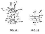
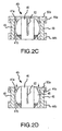
Figs. 2A, 2B ,2C and 2D illustrate an exploded view, an assembled side view, and two cross-sectional side views (i.e., taken along cross-section line AA ofFig. 2B ), respectively, of a swivel assembly embodiment shown in the embodiment ofFig. 1 . -
Figs. 3A, 3B and 3C illustrate an exploded view, an assembled top view and a cross-sectional side view (i.e., taken along cross-section line AA ofFig. 3B ), respectively, of a carrier assembly embodiment shown in the embodiment ofFig. 1 . -
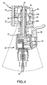
Fig. 4 is a cross-sectional view of the various components illustrated inFig. 1 interconnected for use. -
Fig. 5 illustrates positioning of the various components shown inFig. 1 during an exemplary implant procedure. - The invention will now be further described with reference to the mounting
apparatus embodiment 10 illustrated inFig. 1 . Such description is for purposes of facilitating an understanding of the invention and other embodiments will be apparent to those skilled in the art. - The mounting
apparatus 10 includes acarrier assembly 20, aswivel assembly 40, and a mountingassembly 60. Such assemblies may be readily interconnected and disposed to cooperate in a manner that allows for selective, three-dimensional positioning of an implantable hearing aid actuator, such asexemplary actuator 80, at a desired location within a patient's skull. - By way of general overview, the
exemplary actuator 80 may be supportably connected to afirst end 22 of thecarrier assembly 20. In turn, thecarrier assembly 20 may be supportably received in anopening 42 provided in theswivel assembly 40 and the assembled carrier assembly20/swivel assembly 40 maybe supportablyinterconnected to a mountingapparatus 62 attached to a patient's skull (e.g. via the insertion ofskull attachment devices 70 throughaperatures 65 of mountinglegs 63 into the skull). As will be further described, the interconnection betweencarrier assembly 20 and swivelassembly 40 provides for pivotable, lateral positioning of thefirst end 22 of thecarrier assembly 20, and of theactuator 80 interconnected thereto. Further,carrier device 20 and swivelassembly 40 may be provided so thatcarrier assembly 20 may be selectively secured along a continuum of positions within theopening 42 of theswivel assembly 40, thereby facilitating advancement/retraction ofthecarrier assembly 20 andinterconnected actuator 80, in a depth dimension. Additionally, thecarrier assembly 20 may be defined so that itsfirst end 22 may be selectively advanced/retracted in the depth dimension relative to anouter support member 24 thereto. - As illustrated in
Fig. 1 ,swivel assembly 40 may be provided in a unitary, or interconnected, form so that it may be readily positioned about theouter support member 24 ofcarrier assembly 20, thereby facilitating positioning and interconnection of theswivel assembly 40 within the mountingapparatus 62. In the later regard, it should be noted that in the illustratedembodiment swivel assembly 40 is configured for mating receipt in a predetermined orientation by a complimentarily configuredbarrel portion 64 of mountingapparatus 62. Further,unitary swivel assembly 40 is sized to supportably rest upon anend plate portion 66 of mountingapparatus 62. As will be further described, whencarrier assembly 20 has been advanced/retracted and pivoted to be in a desired linear and angular position, a lockingmember 68, positionable within a top end of thebarrel 64 of mountingapparatus 62, may be tightened against the top ofswivel assembly 40 to "lock-in" the desired linear and angular position ofcarrier assembly 20. - To facilitate such functionality, one embodiment of
swivel assembly 40 will now be discussed in detail with reference toFigs. 2A - 2D . As illustrated,swivel assembly 40 includes opposing, top andbottom plate members rotatable ball member 46 therebetween. In particular, the top andbottom plate members apertures ball member 46 is seated between thebeveled surfaces rotatable ball member 46 also includes anaperture 47 there through which, together withapertures opening 42 ofswivel assembly 40. In this regard,aperture 47 may be sized to slidably receive theouter support member 24, yet restrain free relative movement therebetween. As will be appreciated, whencarrier assembly 20 is positioned throughopening 42, pivotal movement of thecarrier assembly 20 will cause rotation of theball member 46. In relation to such movement,apertures aperture 47 so as to permit pivotal movement ofcarrier assembly 20 within a predetermined range of motion. By way of example,swivel assembly 20 may be provided so as to permitcarrier assembly 20 to pivot up to 30° about and relative to a center axis passing through theapertures - The top and
bottom plate members headed pins 48 which are inserted throughapertures bottom plate members apertures 50b defined in thebottom plate member 44b are sized for retentive press-fit receipt of the bottom ends of headed pins 48. On the other hand, theapertures 50a defined intop plate member 44a are sized relative to the headed pins 48 to permit a small degree of linear travel therebetween (e.g., about 01"), thereby allowing theball member 46 to rotate relative to the top andbottom plate members swivel assembly 40. For purposes of illustrating the rotatability/lockability ofball member 46,Figs. 2C and 2D illustrateswivel assembly 40 with thetop plate member 44a in a "lifted" position and in a "compressed" position, respectively. - In the later regard, and as noted above in relation to the embodiment of
Fig. 1 , a lockingmember 68 may be provided to apply a force to thetop plate member 44a to lock-in a desired linear and angular disposition of thecarrier assembly 20 shown inFig.1 . For such purposes,rotatable ball member 46 includes fourslits 52 which extend fromaperture 47 through a top portion of theball member 46 to define four slightly separated upper sections. Of importance, slits 52 extend through only a portion of therotatable ball member 46. Consequently, and as shown byFig. 2D , upon the application of a force to the top surface of thetop plate member 44a (e.g., by the lockingmember 68 as described above), thebeveled surface 41 a of thetop plate member 44a will act to apply on inward force about a top end of theball member 46 so as to urge the four upper sections thereof inwards. As such, whencarrier assembly 20 is positioned within theopening 42 ofswivel assembly 40, the inward motion of the top sections ofball member 46 may serve to lock-in a given linear position of thecarrier assembly 20 relative to theswivel assembly 40. Further, upon the application of downward force to thetop plate member 44a, beveled,annular surface 41a of thetop plate member 44a will act to apply downward forces about the contacted ring portion ofball member 46, thereby serving to lock-in a given rotational orientation ofball member 46 relative to the top andbottom plate members carrier assembly 20 is positioned in theopening 42 ofswivel assembly 42 the ability to lock-in a given rotational orientation ofball member 46 allows thecarrier assembly 20 to be set in a desired angular position. - Reference will now be made to
Figs. 3A - 3C which illustrate one embodiment of thecarrier assembly 20 shown inFig. 1 . Theillustrated carrier assembly 20 includes anouter support member 24, aninner shaft member 26 and an extendable, or telescoping,shaft member 28 having a foot-like configuration which defines thefirst end 22 of thecarrier assembly 20. In the illustrated embodiment,inner shaft member 26 is threaded for driven engagement with an internally threaded surface withintelescoping support member 28. In this regard, aring portion 30 is provided at the top end of theinternal shaft 26 and is sized for rotatable positioning in a bushing arrangement defined by top andbottom ring members bottom ring members ring portion 30 of theinternal shaft member 26, and the adjoinedrings top end 34 of theouter tube member 24. Such an arrangement axially fixesinternal shaft member 26 relative to theouter support member 24, but allows theinternal shaft member 26 to be rotated relative to theouter support member 24, e.g., via driven engagement by an accessory tool with a hex-end 36 provided at the top end of theinternal shaft member 26. - As noted, telescoping
support member 28 may be provided with an internally threaded surface for threaded engagement with theinner shaft member 26. Further, telescopingsupport member 28 may include anouter groove 38 extending along the length of thetelescoping support member 28.Such groove 38 is provided to co-act with a restrainingmember 39 projecting from theouter support member 24. More particularly, whenouter support member 24 is in a locked position as described above, restrainingmember 39 acts to restraintelescoping support member 28 from rotation relative toouter support member 24 upon driven rotation ofinner shaft 24. As such, upon driven rotation ofinner shaft member 26, thetelescoping support member 28, and animplantable actuator 80 interconnected to the footedfirst end 22 thereof, may be selectively advanced/retracted relative to theouter support member 24 andinner shaft member 26. - Referring now to
Figs. 1 ,4 and5 , interconnection and use of the various components in one application of the described embodiment will be reviewed. Initially, and as shown inFig. 5 , anopening 100 in the mastoid process of a patient's skull may be defined by drilling or other appropriate process. Theopening 100 should be of size sufficient to accommodate insertion of acylindrical barrel portion 64 of the mountingapparatus 62 therethrough. In this regard,Fig. 1 illustrates a mountingassembly 60 for which skull attachment of the mountingapparatus 62 is achieved via the use ofattachment devices 70 inserted throughapertures 65 provided in radiating mountinglegs 63 at the top end of the mountingapparatus 62. In an alternate embodiment, as shown inFigs. 4 and5 , thecylindrical barrel portion 64 may be provided withexternal threads 67 for threaded engagement with a tapped bore portion defined within theopening 100 of a patient's skull. - After securement of the mounting
apparatus 62 to a patient's skull, various components of thepositioning embodiment 10, together with aninterconnected actuator 80, maybe positioned through the mountingapparatus 62. In this regard, interconnection of the various components of thepositioning assembly 10, as well as interconnection of thepositioning assembly 10 toactuator 80, may be completed in conjunction with an implant procedure, or alternatively, may be at least partially completed as part of a production/assembly operation prior to shipment. In either case, before positioning within the mountingapparatus 62, footedfirst end 22 oftelescoping support member 28 of thecarrier assembly 20 may be slidably disposed within achannel 88 provided at the top end of actuator 80 abody portion 84, and swivelassembly 40 may be positioned as a unit about theouter support member 24 of thecarrier assembly 20. In the later regard, and as noted above, theopening 42 defined throughswivel assembly 40 may be sized for slidable friction fit with the outside surface of thesupport member 24 so as to allow for slidable relative positioning between the two, as well as a degree ofretention that restrictsswivel assembly 40 from simply sliding off thecarrier assembly 20. - In positioning the
interconnected positioning assembly 10 andactuator 80 within the mountingapparatus 62, it may be noted that tab-like extensions of the top andbottom plate members swivel assembly 40, as well as rectangular portions of the footedfirst end 22 andactuator 80, as well as asignal transmission cable 86 comprisingactuator 80, may all be aligned relative to acomplimentary opening 69 provided along one side of thebarrel portion 64 of the mountingapparatus 62. Theinterconnected positioning assembly 10 andactuator 80 may then be linearly advanced through thebarrel portion 64 of mountingapparatus 62 until thebottom plate member 44b ofswivel assembly 40 supportably engages thebottom end plate 66 of the mountingapparatus 62. Then, the lockingring 68 may be located in the top end of thebarrel portion 64, but not yet tightened againstswivel assembly 40. Thepositioning apparatus 10 is now disposed for selective positioning ofactuator 80. - In particular, an
accessory tool 200 may be inserted through an aperture in lockingring 68 to engage the hex-end 36 of theinternal shaft member 26 ofcarrier assembly 20. Using theaccessary tool 200 thehearing aid actuator 80 may be selectively advanced/retracted into a preliminarily desired depth position via slidable advancement/retraction oftheouter support member 24 of thecarrier assembly 20 within theopening 42 of theswivel assembly 40. Further, the angular orientation of theactuator 80 may be selectively adjusted via use of theaccessory tool 200 to effect pivotal movement of thecarrier assembly 20 and rotation ofball member 46 relative to the top andbottom plate members swivel assembly 40. - In this regard, where
actuator 80 comprises an electromechanical transducer (e.g. as shown inFigs. 1 ,4 and5 ), aprobe tip 82 of theactuator 80 may be pivoted into a position where it is directed towards a desiredcontact location 120 on theincus bone 110. Further in this regard, prior to insertion of thepositioning apparatus 10 through mountingapparatus 60, a small hole may be defined at the desiredcontact location 120 on the surface of the incus 110 (e.g., via use of a laser guide arrangement). It should be noted that the contact location maybe defined on other ossicular bones or even perhaps the oval window. - When the
probe tip 82 of theelectromechanical transducer actuator 80 is angularly directed towards the desiredcontact location 120, the lockingring 68 may be further advanced within thebarrel portion 64 of the mountingapparatus 60 so as lock in the set angular orientation and depth setting of thecarrier assembly 20. Then, to achieve precise positioning of the probe tip 82 a further accessory tool (not shown) may be inserted through the aperture of the mounting/locking ring 68 to natingly engage the hex-end 36 of theinternal shaft member 26 of thecarrier assembly 20 for driven rotation thereof. In this regard, it should be appreciated that the threading provided on theinternal shaft member 26 andtelescoping shaft member 28 may be defined so that, for a given amount of driven rotation of the hex-end 36, a corresponding predetermined desire of linear travel by thefirst end 22 of thetelescoping shaft member 28 will be affected (e.g., 1/4 mm travel for each complete rotation). As such, after theprobe tip 82 has been advanced into initial contact with theincus 110, a predetermined degree of loading may be selectively established by driven rotation of hex-end 36 a predetermined number of revolutions. As will be appreciated, the ability to achieve precise positioning, and loading of anactuator 80 relative to the ossicular chain, yields enhanced acoustic signal transmission and overall improved hearing aid performance. After positioning of theactuator 80, placement of and connections between other implanted components of a given hearing aid system may be completed prior to system testing and surgical sew-up. - The description provided above is solely for purposes of facilitating an understanding of one embodiment of the present invention. Additional embodiments will be apparent to those skilled in the art. For example, while the embodiment described may employ an
electromechanical transducer actuator 80, aspects of the present invention are also employed for positioning other types of implantable hearing aid actuators. Such alternative applications as well as modifications and adaptations of the described embodiment are intended to be within the scope of the present invention as defined by the claims which follow.
Claims (15)
- An apparatus for supportably positioning an implantable hearing aid actuator within a patient's skull, comprising:a carrier device (20) for carrying an implantable hearing aid actuator (80) at a first-end of said carrier device wherein said first-end of said carrier device is pivotable in first and second dimensions; anda mounting device (60) for mounting said apparatus to a patient's skull;a swivel device (40) for pivotably supporting said carrier device relative to said mounting devicecharacterised in that the swivel device is unitary and comprises:wherein said unitary swivel device (40) is selectively securable as a single unit to said mounting device (60).interconnected, opposing first and second holder members (44a,44b); anda pivot member (46) captured between said first and second holder members
- An apparatus as recited in Claim 1, wherein said carrier device (20) is selectively positionable in a third dimension relative to said swivel device (40).
- An apparatus as recited in Claim 1, wherein said pivot member (46) includes an opening (47) for supportably receiving said carrier device (20).
- An apparatus as recited in Claim 3, wherein said carrier device (20) is slidably positionable in said opening (47) along a continuum of positions in said third dimension.
- An apparatus as recited in Claim 4, wherein said first and second holder members (44a,44b) are interconnected to permit relative movement therebetween.
- An apparatus as recited in Claim 5, further including: a locking member (68) interconnectable to said mounting device (60) to selectively restrict said relative movement between said first and second holder members (44a,44b), wherein a selected angular orientation between said carrier device (20) and said mounting device (60) is maintainable by said locking member.
- An apparatus as recited in Claim 6, wherein said pivot member (46) comprises a plurality of slits (52) extending through a portion thereof to define a plurality of separated, upper portions of the pivot member, and wherein said locking member (68) is interconnectable to said mounting device to effect inward movement of said upper portions of said pivot member (46) and thereby restrictably engage said carrier member (20) in a selected one of said continuum of positions.
- An apparatus as recited in Claim 2, wherein said carrier device (20) comprises: a first carrier member (26); and a second carrier member (28) supportably interconnected to and selectively advancable in said third dimension relative to said first carrier member.
- An apparatus as recited in Claim 8, wherein said first and second carrier members (26,28) are disposed coaxially and interconnected for selective, telescoping advancement and retraction of said second carrier member (28) relative to said first carrier member (26).
- An apparatus as recited in claim 1, wherein:said carrier device (20) includes a first carrier member (26) and a second carrier member (28) that is supportably interconnected to and selectively advancable relative to said first carrier member in a first dimension;said carrier device (20), which includes said first and second carrier members (26,28), is linearly advancable in said first dimension relative to said swivel device (40), and wherein said first end of said carrier device is pivotable in second and third dimensions relative to said swivel device (40).
- An apparatus as recited in Claim 10, wherein said first and second carrier members (26,28) are disposed coaxially and interconnected for selective, telescoping advancement and retraction of said second carrier member (28) relative to said first carrier member (26).
- An apparatus as recited in Claim 10, wherein said first and second carrier members (26,28) are threadably interconnected, and wherein driven rotation of said first carrier member (26) effects a predetermined degree of linear travel by said second carrier member (28).
- An apparatus as recited in Claim 10, said carrier device (20) further comprising: a third carrier member (24) rotatably interconnected to said first carrier member (26), for direct engagement with said swivel device (40) and for restricting rotational movement of said second carrier member (28).
- An apparatus as recited in Claim 13, wherein said second carrier member (28) includes a linear slot (38), and wherein said third carrier member (24) includes a projecting restraining member pin (39) positioned within said slot of said second carrier member.
- An apparatus as recited in Claim 14, wherein said swivel device (40) includes:interconnected, opposing first and second holder members (44a,44b); anda pivot member (46) captured between said first and second holder members and having an opening (47) therethrough for slidable, direct engagement with said third carrier member (24).
Applications Claiming Priority (3)
| Application Number | Priority Date | Filing Date | Title |
|---|---|---|---|
| US583299 | 2000-05-30 | ||
| US09/583,299 US6491622B1 (en) | 2000-05-30 | 2000-05-30 | Apparatus and method for positioning implantable hearing aid device |
| PCT/US2001/008695 WO2001093636A1 (en) | 2000-05-30 | 2001-03-19 | Improved apparatus and method for positioning implantable hearing aid device |
Publications (3)
| Publication Number | Publication Date |
|---|---|
| EP1285557A1 EP1285557A1 (en) | 2003-02-26 |
| EP1285557A4 EP1285557A4 (en) | 2006-04-26 |
| EP1285557B1 true EP1285557B1 (en) | 2009-01-21 |
Family
ID=24332513
Family Applications (1)
| Application Number | Title | Priority Date | Filing Date |
|---|---|---|---|
| EP01922459A Expired - Lifetime EP1285557B1 (en) | 2000-05-30 | 2001-03-19 | Improved apparatus and method for positioning implantable hearing aid device |
Country Status (6)
| Country | Link |
|---|---|
| US (1) | US6491622B1 (en) |
| EP (1) | EP1285557B1 (en) |
| JP (1) | JP3814538B2 (en) |
| AT (1) | ATE421844T1 (en) |
| DE (1) | DE60137498D1 (en) |
| WO (1) | WO2001093636A1 (en) |
Families Citing this family (39)
| Publication number | Priority date | Publication date | Assignee | Title |
|---|---|---|---|---|
| DE10047388C1 (en) * | 2000-09-25 | 2002-01-10 | Implex Hear Tech Ag | Implantable hearing system, includes a detachable coupling for securing and locating a transducer and a micro-manipulator |
| US7273447B2 (en) * | 2004-04-09 | 2007-09-25 | Otologics, Llc | Implantable hearing aid transducer retention apparatus |
| US20050101830A1 (en) * | 2003-11-07 | 2005-05-12 | Easter James R. | Implantable hearing aid transducer interface |
| US7137946B2 (en) * | 2003-12-11 | 2006-11-21 | Otologics Llc | Electrophysiological measurement method and system for positioning an implantable, hearing instrument transducer |
| WO2005101903A2 (en) * | 2004-04-09 | 2005-10-27 | Otologics, Llc | Implantable hearing aid systems |
| US7186211B2 (en) * | 2004-04-09 | 2007-03-06 | Otologics, Llc | Transducer to actuator interface |
| US7153257B2 (en) * | 2004-04-09 | 2006-12-26 | Otologics, Llc | Implantable hearing aid transducer system |
| US7160244B2 (en) * | 2004-05-10 | 2007-01-09 | Patrik Westerkull | Arrangement for a hearing aid |
| WO2006031767A2 (en) * | 2004-09-10 | 2006-03-23 | Otologics, Llc | Adjustable bone bracket |
| ES2288335B1 (en) * | 2004-11-04 | 2008-11-16 | Instituto Cientifico Y Tecnologico De Navarra, S.A. | SUPPORT TO STRENGTHEN A SURGICAL TOOL. |
| EP1851994B1 (en) | 2005-01-11 | 2015-07-01 | Cochlear Limited | Active vibration attenuation for implantable microphone |
| US7582052B2 (en) * | 2005-04-27 | 2009-09-01 | Otologics, Llc | Implantable hearing aid actuator positioning |
| WO2007147071A2 (en) * | 2006-06-14 | 2007-12-21 | Otologics, Llc | Compressive coupling of an implantable hearing aid actuator to an auditory component |
| US7722525B2 (en) * | 2007-05-24 | 2010-05-25 | Otologics, Llc | Lateral coupling of an implantable hearing aid actuator to an auditory component |
| DK2208367T3 (en) | 2007-10-12 | 2017-11-13 | Earlens Corp | Multifunction system and method for integrated listening and communication with noise cancellation and feedback management |
| KR101568452B1 (en) | 2008-06-17 | 2015-11-20 | 이어렌즈 코포레이션 | Optical electro-mechanical hearing devices with separate power and signal components |
| WO2010017561A1 (en) * | 2008-08-08 | 2010-02-11 | Otologics, Llc | Systems and methods for securing subcutaneous implantaed devices |
| EP3509324B1 (en) | 2008-09-22 | 2023-08-16 | Earlens Corporation | Balanced armature devices and methods for hearing |
| EP2434968A1 (en) * | 2009-05-29 | 2012-04-04 | Asalus Medical Instruments Limited | Laparoscopic access port and port sleeve arrangement |
| US9544700B2 (en) * | 2009-06-15 | 2017-01-10 | Earlens Corporation | Optically coupled active ossicular replacement prosthesis |
| WO2010148345A2 (en) | 2009-06-18 | 2010-12-23 | SoundBeam LLC | Eardrum implantable devices for hearing systems and methods |
| KR101833073B1 (en) | 2009-06-18 | 2018-02-27 | 이어렌즈 코포레이션 | Optically coupled cochlear implant systems and methods |
| EP2446646B1 (en) | 2009-06-22 | 2018-12-26 | Earlens Corporation | Hearing device for coupling to the round window |
| WO2010133706A2 (en) * | 2010-09-27 | 2010-11-25 | Advanced Bionics Ag | Hearing instrument for round or oval window stimulation |
| WO2010133704A2 (en) * | 2010-09-27 | 2010-11-25 | Advanced Bionics Ag | Implantable hearing instrument |
| DK2656639T3 (en) | 2010-12-20 | 2020-06-29 | Earlens Corp | Anatomically adapted ear canal hearing aid |
| US8790237B2 (en) | 2011-03-15 | 2014-07-29 | Cochlear Limited | Mechanical stimulator having a quick-connector |
| US10034103B2 (en) | 2014-03-18 | 2018-07-24 | Earlens Corporation | High fidelity and reduced feedback contact hearing apparatus and methods |
| WO2016011044A1 (en) | 2014-07-14 | 2016-01-21 | Earlens Corporation | Sliding bias and peak limiting for optical hearing devices |
| US9924276B2 (en) | 2014-11-26 | 2018-03-20 | Earlens Corporation | Adjustable venting for hearing instruments |
| US20170095202A1 (en) | 2015-10-02 | 2017-04-06 | Earlens Corporation | Drug delivery customized ear canal apparatus |
| US10321247B2 (en) | 2015-11-27 | 2019-06-11 | Cochlear Limited | External component with inductance and mechanical vibratory functionality |
| US20170195806A1 (en) | 2015-12-30 | 2017-07-06 | Earlens Corporation | Battery coating for rechargable hearing systems |
| US11350226B2 (en) | 2015-12-30 | 2022-05-31 | Earlens Corporation | Charging protocol for rechargeable hearing systems |
| US10492010B2 (en) | 2015-12-30 | 2019-11-26 | Earlens Corporations | Damping in contact hearing systems |
| WO2018048794A1 (en) | 2016-09-09 | 2018-03-15 | Earlens Corporation | Contact hearing systems, apparatus and methods |
| WO2018093733A1 (en) | 2016-11-15 | 2018-05-24 | Earlens Corporation | Improved impression procedure |
| WO2019173470A1 (en) | 2018-03-07 | 2019-09-12 | Earlens Corporation | Contact hearing device and retention structure materials |
| WO2019199680A1 (en) | 2018-04-09 | 2019-10-17 | Earlens Corporation | Dynamic filter |
Family Cites Families (21)
| Publication number | Priority date | Publication date | Assignee | Title |
|---|---|---|---|---|
| GB1304837A (en) | 1969-02-07 | 1973-01-31 | ||
| US4281419A (en) | 1979-12-10 | 1981-08-04 | Richards Manufacturing Company, Inc. | Middle ear ossicular replacement prosthesis having a movable joint |
| US4655776A (en) | 1984-01-12 | 1987-04-07 | Oto Enterprises, Inc. | Prostheses for ossicular reconstruction |
| US4601723A (en) | 1985-01-29 | 1986-07-22 | Mcgrew Robert N | Telescoping self-adjusting ossicular prostheses |
| US5024224A (en) | 1988-09-01 | 1991-06-18 | Storz Instrument Company | Method of readout of implanted hearing aid device and apparatus therefor |
| US5085628A (en) | 1988-09-09 | 1992-02-04 | Storz Instrument Company | Implantable hearing aid coupler device |
| US4922333A (en) | 1988-12-15 | 1990-05-01 | Eastman Kodak Company | Video copying apparatus spectrally-responsive to slides or negatives |
| US5217011A (en) | 1989-06-20 | 1993-06-08 | Storz Instrument Company | Method and apparatus for transdermal communication |
| US5282858A (en) | 1991-06-17 | 1994-02-01 | American Cyanamid Company | Hermetically sealed implantable transducer |
| US5370689A (en) | 1992-07-23 | 1994-12-06 | Xomed-Treace, Inc. | Method of implanting a middle ear prosthesis |
| US5702342A (en) | 1993-10-14 | 1997-12-30 | Otologics Llc. | Directionally-controllable mounting apparatus |
| FR2712481B1 (en) | 1993-11-18 | 1996-01-12 | Graf Henry | Improvements to flexible inter-vertebral stabilizers. |
| DE19618964C2 (en) * | 1996-05-10 | 1999-12-16 | Implex Hear Tech Ag | Implantable positioning and fixing system for actuator and sensory implants |
| DE19618945C2 (en) * | 1996-05-10 | 2003-02-27 | Phonak Ag Staefa | Fixable positioning system for a firm, play-free connection to the human skull |
| US6001129A (en) | 1996-08-07 | 1999-12-14 | St. Croix Medical, Inc. | Hearing aid transducer support |
| US5954628A (en) | 1997-08-07 | 1999-09-21 | St. Croix Medical, Inc. | Capacitive input transducers for middle ear sensing |
| US5993376A (en) | 1997-08-07 | 1999-11-30 | St. Croix Medical, Inc. | Electromagnetic input transducers for middle ear sensing |
| DE19738587C1 (en) | 1997-09-03 | 1999-05-27 | Implex Gmbh | Arrangement for setting and fixing the relative position of two elements of an active or passive hearing implant |
| US6077215A (en) * | 1998-10-08 | 2000-06-20 | Implex Gmbh Spezialhorgerate | Method for coupling an electromechanical transducer of an implantable hearing aid or tinnitus masker to a middle ear ossicle |
| US6113531A (en) * | 1998-11-18 | 2000-09-05 | Implex Aktiengesellschaft Hearing Technology | Process for optimization of mechanical inner ear stimulation in partially or fully implantable hearing systems |
| DE19858398C1 (en) * | 1998-12-17 | 2000-03-02 | Implex Hear Tech Ag | Tinnitus treatment implant comprises a gas-tight biocompatible electroacoustic transducer for implantation in a mastoid cavity |
-
2000
- 2000-05-30 US US09/583,299 patent/US6491622B1/en not_active Expired - Lifetime
-
2001
- 2001-03-19 JP JP2001588290A patent/JP3814538B2/en not_active Expired - Fee Related
- 2001-03-19 DE DE60137498T patent/DE60137498D1/en not_active Expired - Fee Related
- 2001-03-19 EP EP01922459A patent/EP1285557B1/en not_active Expired - Lifetime
- 2001-03-19 AT AT01922459T patent/ATE421844T1/en not_active IP Right Cessation
- 2001-03-19 WO PCT/US2001/008695 patent/WO2001093636A1/en active Application Filing
Also Published As
| Publication number | Publication date |
|---|---|
| DE60137498D1 (en) | 2009-03-12 |
| JP3814538B2 (en) | 2006-08-30 |
| JP2004508742A (en) | 2004-03-18 |
| WO2001093636A1 (en) | 2001-12-06 |
| EP1285557A4 (en) | 2006-04-26 |
| US6491622B1 (en) | 2002-12-10 |
| EP1285557A1 (en) | 2003-02-26 |
| ATE421844T1 (en) | 2009-02-15 |
Similar Documents
| Publication | Publication Date | Title |
|---|---|---|
| EP1285557B1 (en) | Improved apparatus and method for positioning implantable hearing aid device | |
| US6293903B1 (en) | Apparatus and method for mounting implantable hearing aid device | |
| US5788711A (en) | Implantable positioning and fixing system for actuator and sensor implants | |
| US8366601B2 (en) | Simplified implantable hearing aid transducer apparatus | |
| EP0904033B1 (en) | Fixing element and ligament fixed with fixing element | |
| US8372073B2 (en) | Multi-pin clamp and rod attachment | |
| US8105229B2 (en) | At least partially implantable hearing system | |
| EP1048320A3 (en) | Adjustable medical lead fixation system | |
| US7722525B2 (en) | Lateral coupling of an implantable hearing aid actuator to an auditory component | |
| EP1813935A3 (en) | Method for automatically aligning a sample in an x-ray diffractometer | |
| WO2010133704A2 (en) | Implantable hearing instrument | |
| JPH11505139A (en) | External fixation device for large bone | |
| US7186211B2 (en) | Transducer to actuator interface | |
| AU2017228520B2 (en) | Mounting assembly for a bone conduction hearing device | |
| US7153257B2 (en) | Implantable hearing aid transducer system | |
| WO2018217187A1 (en) | Methods and apparatus for use with cochlear implants having magnet apparatus with magnetic material particles | |
| US20080200928A1 (en) | Support for Steadying a Surgical Tool | |
| US20080004486A1 (en) | Compressive coupling of an implantable hearing aid actuator to an auditory component | |
| CN114027896A (en) | Posterior cranial fovea retractor for neurosurgery operation | |
| US20030229262A1 (en) | Apparatus and method for ossicular fixation of implantable hearing aid actuator | |
| WO2012041400A1 (en) | Hearing instrument for round or oval window stimulation | |
| US11786385B2 (en) | Osseointegration system | |
| WO2005101903A2 (en) | Implantable hearing aid systems |
Legal Events
| Date | Code | Title | Description |
|---|---|---|---|
| PUAI | Public reference made under article 153(3) epc to a published international application that has entered the european phase |
Free format text: ORIGINAL CODE: 0009012 |
|
| 17P | Request for examination filed |
Effective date: 20021023 |
|
| AK | Designated contracting states |
Kind code of ref document: A1 Designated state(s): AT BE CH CY DE DK ES FI FR GB GR IE IT LI LU MC NL PT SE TR |
|
| RBV | Designated contracting states (corrected) |
Designated state(s): AT DE ES FR GB IT |
|
| A4 | Supplementary search report drawn up and despatched |
Effective date: 20060310 |
|
| GRAP | Despatch of communication of intention to grant a patent |
Free format text: ORIGINAL CODE: EPIDOSNIGR1 |
|
| GRAS | Grant fee paid |
Free format text: ORIGINAL CODE: EPIDOSNIGR3 |
|
| GRAA | (expected) grant |
Free format text: ORIGINAL CODE: 0009210 |
|
| AK | Designated contracting states |
Kind code of ref document: B1 Designated state(s): AT DE ES FR GB IT |
|
| REG | Reference to a national code |
Ref country code: GB Ref legal event code: FG4D |
|
| REF | Corresponds to: |
Ref document number: 60137498 Country of ref document: DE Date of ref document: 20090312 Kind code of ref document: P |
|
| PG25 | Lapsed in a contracting state [announced via postgrant information from national office to epo] |
Ref country code: ES Free format text: LAPSE BECAUSE OF FAILURE TO SUBMIT A TRANSLATION OF THE DESCRIPTION OR TO PAY THE FEE WITHIN THE PRESCRIBED TIME-LIMIT Effective date: 20090502 |
|
| PG25 | Lapsed in a contracting state [announced via postgrant information from national office to epo] |
Ref country code: AT Free format text: LAPSE BECAUSE OF FAILURE TO SUBMIT A TRANSLATION OF THE DESCRIPTION OR TO PAY THE FEE WITHIN THE PRESCRIBED TIME-LIMIT Effective date: 20090121 |
|
| PLBE | No opposition filed within time limit |
Free format text: ORIGINAL CODE: 0009261 |
|
| STAA | Information on the status of an ep patent application or granted ep patent |
Free format text: STATUS: NO OPPOSITION FILED WITHIN TIME LIMIT |
|
| REG | Reference to a national code |
Ref country code: FR Ref legal event code: ST Effective date: 20091130 |
|
| 26N | No opposition filed |
Effective date: 20091022 |
|
| PG25 | Lapsed in a contracting state [announced via postgrant information from national office to epo] |
Ref country code: DE Free format text: LAPSE BECAUSE OF NON-PAYMENT OF DUE FEES Effective date: 20091001 |
|
| PG25 | Lapsed in a contracting state [announced via postgrant information from national office to epo] |
Ref country code: FR Free format text: LAPSE BECAUSE OF NON-PAYMENT OF DUE FEES Effective date: 20091123 |
|
| PG25 | Lapsed in a contracting state [announced via postgrant information from national office to epo] |
Ref country code: IT Free format text: LAPSE BECAUSE OF FAILURE TO SUBMIT A TRANSLATION OF THE DESCRIPTION OR TO PAY THE FEE WITHIN THE PRESCRIBED TIME-LIMIT Effective date: 20090121 |
|
| PGFP | Annual fee paid to national office [announced via postgrant information from national office to epo] |
Ref country code: GB Payment date: 20110316 Year of fee payment: 11 |
|
| GBPC | Gb: european patent ceased through non-payment of renewal fee |
Effective date: 20120319 |
|
| PG25 | Lapsed in a contracting state [announced via postgrant information from national office to epo] |
Ref country code: GB Free format text: LAPSE BECAUSE OF NON-PAYMENT OF DUE FEES Effective date: 20120319 |