EP1285215B1 - An automatic cocking device in a crossbow for hunting and archery - Google Patents
An automatic cocking device in a crossbow for hunting and archery Download PDFInfo
- Publication number
- EP1285215B1 EP1285215B1 EP01932058A EP01932058A EP1285215B1 EP 1285215 B1 EP1285215 B1 EP 1285215B1 EP 01932058 A EP01932058 A EP 01932058A EP 01932058 A EP01932058 A EP 01932058A EP 1285215 B1 EP1285215 B1 EP 1285215B1
- Authority
- EP
- European Patent Office
- Prior art keywords
- crossbow
- bowstring
- trigger block
- frame
- electromechanical means
- Prior art date
- Legal status (The legal status is an assumption and is not a legal conclusion. Google has not performed a legal analysis and makes no representation as to the accuracy of the status listed.)
- Expired - Lifetime
Links
Images


Classifications
-
- F—MECHANICAL ENGINEERING; LIGHTING; HEATING; WEAPONS; BLASTING
- F41—WEAPONS
- F41B—WEAPONS FOR PROJECTING MISSILES WITHOUT USE OF EXPLOSIVE OR COMBUSTIBLE PROPELLANT CHARGE; WEAPONS NOT OTHERWISE PROVIDED FOR
- F41B5/00—Bows; Crossbows
- F41B5/12—Crossbows
Definitions
- the present invention relates to an automatic cocking device in a crossbow for hunting and/or archery.
- Crossbows are known in which cocking is facilitated by the presence of a ring in the frontal area of the crossbows into which the shooter inserts a foot, so that with the crossbow bearing on the ground and secured by his/her foot, the shooter can pull the bowstring towards him/her with his/her hands until bringing it in the position in which it catches the shooting device associated to the trigger.
- Another manual cocking system already used in medieval times, comprises a crank to be operated by the shooter to tension the bowstring by means of reducing mechanisms, but such a solution is operatively complex and the lesser effort required is paid for with an excessively long cocking time.
- a crossbow in which the trigger assembly can translate along the longitudinal axis of the crossbow. In a first phase the trigger assembly translates towards the flexing elements to catch the bowstring and in a second phase the operator tensions the bowstring, returning the trigger device to the rear position.
- the cocking action therefore takes place manually, acting on the trigger assembly instead of directly on the spring.
- Such a crossbow has the drawbacks of a manually cocked crossbow especially as regards the efforts the operator must exert during the cocking phase.
- the device comprises a shaft which is at least partly threaded and which translates relative to the case on a guide and support walls, actuated by the electric motor.
- the electric motor sets in rotation (clockwise or counter-clockwise depending on the position of a switch) a drive shaft whereon is keyed a first gear wheel which meshes onto a second gear wheel mounted on a sleeve having an inner thread which couples with the outer thread of the threaded shaft that translates relative to the sleeve in such a way as to transform the rotational motion of the drive shaft into translating motion of the threaded shaft relative to the trigger of the crossbow.
- End stop sensors are provided to check the run of the threaded shaft.
- this solution which is the only one described in the patent, provides for the rather bulky housing that contains the motor and the battery to be located in the front area of the crossbow in front of the shooting area, in a rather inconvenient position and which, in any case, requires the housing to be removed prior to shooting, both because of the impossibility of releasing the arrow and because the weight of the device on the tip of the crossbow would create an imbalance which would prevent the shooter from shouldering it correctly and from aiming properly.
- the aforesaid patent fails to teach how to fasten the device in a permanent manner without influencing the balance of the crossbow and consequently penalising the shooting phase.
- a manually and operable system for cocking the bowstring of a crossbow is disclosed by US 5,823,172, wherein a mechanically operated device for drawing a bowstring with an uniform tension or either side of the crossbow stock is described.
- the cocking device is not an electromechanical automatic cocking device, acts on the bowstring through an inclined fork which can only push and not pull the bowstring and so the device has to be placed on the front edge of the crossbow and has to be removed before shooting.
- the aim of the present invention is to eliminate the aforesaid drawbacks and to make available a device for automatically cocking a crossbow applicable to the crossbow itself in a fixed manner, with no need to remove it every time one shoots.
- Another aim is to avoid frictions and jams during the crossbow cocking phase.
- a further aim is to achieve the above in a simple and reliable manner, without increasing the length or generally the dimensions of the crossbow itself and thus avoiding imbalances which would adversely effect the shooting phase.
- the trigger block can translate on rectilinear path parallel to the longitudinal axis of the crossbow, in which in a first phase the trigger block advances towards the flexing element until the means for catching and releasing the bowstring automatically catch the bowstring, and in a second phase the trigger block moves back until reaching a position of correct tensioning of the bowstring in which the operation of the trigger causes the instantaneous release of the bowstring, and in that it comprises electromechanical means so shaped as to produce on the trigger block a force substantially parallel to the shooting axis of the crossbow to carry out said first and second phase.
- the electromechanical means for automatically tensioning the bowstring comprise an electric motor anchored underneath the crossbow in the area between the trigger block and the butt, and powered by a battery preferably housed at the rear part of the crossbow frame or at a grip of the crossbow itself.
- the electromechanical means preferably comprise a ball screw show low-friction rotation causes the movement of a sleeve associated to the trigger block by means of a draw wire sliding on pulleys.
- the crossbow can also be provided with a flexing element divided into two halves, each pivotally engaged to the crossbow with the ability to rotate relative thereto in order to be easily made operative by tensioning the bowstring.
- the number 1 globally refers to a hunting crossbow (though it could also be an archery crossbow) which in some figures is shown without its covering fairing, the better to highlight its internal components.
- the crossbow 1 comprises a frame 2 which extends longitudinally and ends frontally with a flexing element 3 for tensioning a bowstring 4, whilst in the rear part it is provided with a butt 5 for the correct positioning of the crossbow by the shooter.
- the frame 2 further comprises two grips 6 and 38 which extends inferiorly from the frame itself to allow the shooter to sustain and operate the crossbow 1.
- the distance between the grip 6 and the butt 5 is smaller than, and in particular equal to about 0.5 - 0.8 times, the distance between the grip 6 and the front end of the crossbow. This solution makes the crossbow extremely compact and easy to handle.
- the frame 2 comprises in the front part two longitudinal and parallel guides 7, whereon slides a trigger block 8 provided with means for catching and releasing the bowstring of a substantially known kind and hence not described in detail herein.
- the trigger block 8 can originally translate on a rectilinear path, parallel to the shooting axis of the crossbow, in which during a first phase the trigger block advances towards the flexing element 3 until the means for catching and releasing the bowstring automatically catch the bowstring 4, and in a second phase the trigger block 8 moves back until reaching a position of correct tensioning of the bowstring in which the operation of the trigger causes the bowstring to be released instantaneously.
- the guides 7 are obtained by means of mutually parallel tension rods and are fastened anteriorly to a support 9, which also sustains the flexing elements, and posteriorly to a plate 10 comprised in the frame 2 and in particular in the portion that embodies the butt 5.
- An electric motor 11 and a battery 12 are associated to the crossbow and substantially incorporated therein.
- the butt 5 intemally houses the electric motor, whilst the battery 12 can advantageously be inserted in the grip 6 of the crossbow.
- the battery 12 therefore is anchored in removable fashion by means of a pushbutton 39.
- the operation of the electric motor causes the rotation of a drive shaft 13 whereon is keyed a first pulley 14 which through a transmission belt 15 sets in rotation a second pulley 16 keyed onto the end of a ball screw 17 housed between the support 9 and the plate 10, parallel and superiorly relative to the shooting axis or longitudinal axis of the crossbow.
- the ball screw is positioned centrally relative to the longitudinal axis of the crossbow, in such a way as not to affect the stability of the crossbow, especially when shooting.
- the ball screw 17 is a known device, essentially comprising a worm screw whereon slides a cylindrical sleeve 18 internally provided with balls what interact with the thread of the screw, allowing 95% efficiency in terms of friction.
- the ball screw 17 is inserted in two bellows 19, respectively introduced between the support 9 and the sleeve 18 and between the sleeve 18 and the plate 10, to protect moving parts.
- the sleeve 18 is connected to the trigger block 8 in such a way that, when the electric motor causes the rotation of the ball screw, the sleeve 18 translates thereon causing a corresponding translation, of equal extent, of the trigger block 8.
- the ball screw 17 also has two shock absorbing elements 20 to brake the run of the sleeve and operate a spring clutch comprised in a spring assembly 26.
- Said shock absorbing elements can be embodied by helical springs or rubber elements.
- the electric motor 11 with the ball screw 17 and the sleeve 18 constitute electromechanical means for the automatic tensioning of the bowstring, originally shaped in such a way as to produce, on the trigger block 8, a force that is substantially parallel to the longitudinal or shooting axis of the crossbow.
- the electromechanical means further comprise a driving element integral with the trigger block, obtained by means of two draw wires 21 actuated by the electric motor.
- the two draw wires 21 are positioned on the sides of the ball screw 17 and each of them has both its ends integral with the trigger block 8.
- the draw wire 21 is integral, in its intermediate position, with the sleeve 18 and slides on pulleys 22 mounted able to rotate on the frame 2 from opposite sides along the run of the trigger block 8.
- an electronic speed control unit for the operation of the electric motor 11, an electronic speed control unit, indicated with 23, is provided together with a control 24 to determine the direction of rotation of the motor (and hence of translation of the trigger assembly).
- the speed control unit 23 and the control 24 can be applied to the grip 6, as shown in Figure 1.
- the electric motor 11 is also provided with an epicyclical reduction gear 25 and with the clutch assembly 26 interposed between the electric motor and the first pulley 14.
- the trigger block 8 is of a substantially known type (apart from the ability to translate) and comprises an actual trigger 27 pivotally engaged on the trigger assembly 8 by means of a bearing and operatively associated to a catch 28 to hold the bowstring 4.
- a safety device 29 comprising a breech bolt 30 and a safety lever 31.
- the flexing element can be subdivided in two halves 3a each of which is pivotally engaged in 32 to the crossbow.
- Each half is so shaped as to be able to rotate relative to the frame 2 to shift from a rest position, in which the two halves are substantially parallel to the frame, to a working position, in which the two halves extend transversely relative to the frame to tension the bowstring, and vice versa.
- means 33 for locking and tensioning the bowstring are provided with the purpose of tensioning the bowstring 4.
- Said means comprise two pivot pins 34 having a first end integral with the frame of the bowstring and able to be inserted into a slot 35 obtained in each of the two halves in proximity to the end pivotally engaged to the frame.
- the locking action is effected by means of threaded elements 36 able to be operatively associated to the pivot pins, by the interposition of an element 37, at least partially cylindrical, to facilitate the placement of the halves in the working position.
- the flexing element can be single and fastened to the crossbow.
- a provisional exterior string is used, tensioning which the flexing element is bent until the actual string can be inserted, according to a known technology.
- the bowstring is automatically engaged in its catching device comprises in the trigger block, automatically engaging the safety device that prevents accidental releases of the arrow.
- the sleeve 18 drives the draw wire 21 which slides along the pulleys 22 and generates the translation of the trigger block 8 until the tun of the sleeve is limited by the shock absorbing elements 20 and arrested by the clutch 26.
- the presence of the two draw wires positioned symmetrically relative to the axis of the crossbow guarantees a balanced, frictionless interaction between the trigger block 8 and the respective guides 7 and exerts on the trigger block a force parallel to the shooting axis of the crossbow.
- the main advantages of the present device consist of the capability to shoot several times with no effort on the operator's part and of the capability to load far greater powers than in current systems, in the capability to uncock the weapon without necessarily shooting the arrow (it is sufficient to operate the electric motor as in the initial phase to move the trigger block closer to the flexing element, thereby reducing the tension on the bowstring), in the availability of a cocking device incorporated in the crossbow itself and in such a position that it does not hamper or hinder the operator in shooting operations.
- a further feature and advantage of the present automatic cocking device is given by the fact that it operates with a force that is parallel to that of the arrow and therefore entails no jams or frictions during the cocking phase or modifications on the trajectory of the arrow during the launching phase.
- the present device further allows to grab the bowstring always in the same place and centrally, avoiding asymmetries.
Landscapes
- Engineering & Computer Science (AREA)
- General Engineering & Computer Science (AREA)
- Adornments (AREA)
- Manufacture Of Motors, Generators (AREA)
- Aiming, Guidance, Guns With A Light Source, Armor, Camouflage, And Targets (AREA)
- Display Devices Of Pinball Game Machines (AREA)
- Crystals, And After-Treatments Of Crystals (AREA)
- Analysing Materials By The Use Of Radiation (AREA)
- Magnetic Resonance Imaging Apparatus (AREA)
Abstract
Description
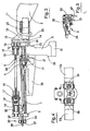
- Figure 1 shows a partially sectioned lateral view of the crossbow;
- Figure 2 shows a partially sectioned top view of the crossbow of Figure 1;
- Figure 3 shows a partially sectioned lateral view of the crossbow of Figure 1;
- Figure 4 shows a front view of the crossbow of Figure 1;
- Figure 5 shows a detail of the crossbow of Figure 3.
Claims (23)
- An automatic cocking device in a crossbow (1) for hunting and/or archery, of the type comprising:characterised in that said trigger block (8) can translate on a rectilinear path with a draw line coaxial to the longitudinal axis of the crossbow, in which in a first phase the trigger block advances towards the flexing element (3) until the means for catching and releasing the bowstring automatically catch the bowstring (4), and in a second phase the trigger block (8) moves back until reaching a position of correct tensioning of the bowstring in which the operation of the trigger causes the instantaneous release of the bowstring, and in that said electromechanical means are so shaped as to produce on the trigger block (8) a force that is substantially coaxial to the shooting axis of the crossbow to carry out said first and second phase.a frame (2) having at least a flexing element (3) and a bowstring (4) strung between opposite ends of the flexing element (3) and positioned substantially perpendicular, under rest conditions, to a shooting axis of the crossbow;electromechanical means for the automatic cocking of the bowstring (4) said electromechanical means comprising at least a feeding device and actuator means;a trigger block (8) provided with means for catching and releasing the bowstring;
- A device as claimed in claim 1, wherein said electromechanical means comprise at least a drawing element integral with the trigger block (8) and actuated by the electromechanical means, the actuator means being integral with the crossbow and placed in such a way as to do not need to be removed before shooting.
- A device as claimed in claim 2, wherein the drawing element is obtained by means of at least a draw wire (21) actuated by the electromechanical means and having at least an end integral with the trigger block (8).
- A device as claimed in claim 3, wherein the draw wire (21) has both its ends integral with the trigger block (8) and slides on rotating pulleys (22) mounted on the frame (2) at opposite sides along the run of the trigger block itself.
- A device as claimed in any of the claims from 2 to 4, wherein said electromechanical means comprise: a ball screw (17) positioned parallel to the longitudinal axis of the crossbow and cinematically connected to an electric motor (11) which causes its actuation; a sleeve (18), sliding on the ball screw towards the front part of the crossbow or towards its rear part depending on the direction of rotation of the balls screw and operatively associated to the drawing element of the trigger block.
- A device as claimed in claim 5, wherein said ball screw (17) comprises at each end a shock absorbing element (20) to brake the run of the sleeve (1'8) and operate a clutch assembly (26).
- A device as claimed in any of the previous claims, wherein the electromechanical means further comprise at least a guide (7) integral with the frame (2) of the crossbow parallel to the longitudinal axis thereof, whereon the trigger block (8) slides.
- A device as claimed in any of the previous claims, wherein the electromechanical means for the automatic tensioning of the bowstring comprise an electric motor (11) anchored in the area between the trigger block (8) and a butt (5) or the rear part of the crossbow, and powered by a battery (12).
- A device as claimed in claim 8, wherein the battery (12) is anchored, in a removable manner by means of a pushbutton (39), to a grip (6) integral with the frame (2) of the crossbow.
- A device as claimed in claim 8, wherein the battery (12) is anchored, in a removable manner, to the rear part of the frame (2) of the crossbow between the trigger block (8) and the butt (5) or terminal part of the crossbow itself.
- A device as claimed in any of the claims from 8 to 10, wherein the electromechanical means for the automatic tensioning of the bowstring comprise an epicyclical reduction gear (25) associated to the electric motor (11).
- A device as claimed in claim 11, wherein the electromechanical means for the automatic tensioning of the bowstring comprise a clutch assembly (26) associated to the electric motor.
- A device as claimed in any of the previous claims, characterised in that the flexing element (3) is divided in two halves (3a), each of which is pivotally engaged to the frame (2) of the crossbow and so shaped as to be able to rotate relative thereto in order to shift from a resting position, in which the two halves are substantially parallel to the frame, to a working position, in which the two halves extend transversely relative to the frame to tension the bowstring, and vice versa.
- A device as claimed in claim 13, wherein each of the halves (3a) comprises means for locking and tensioning (33) the bowstring operating to shift from the resting position to the working position.
- A device as claimed in claim 14, wherein the locking and tensioning means (33) comprise: two pivot pins (34) having a first end integral with the frame (2) of the crossbow; a slot (35) obtained in each of the two halves in proximity to the end pivotally engaged to the frame to receive said pivot pin (34); threaded elements (36) able to be operatively associated to said pivot pin (34) to lock the two halves (3a) in the working position.
- A device as claimed in claim 15, wherein the locking and tensioning means (33) further comprise an element (37) that is at least partially cylindrical and inserted between one half(3a) and the respective threaded element to facilitate the placement of the halves in the working position.
- A crossbow, characterised in that it incorporates a device as claimed in any of the previous claims.
- A crossbow as claimed in claim 17, wherein the distance between a grip (6) and a butt (5) is lesser than the distance between the grip (6) and the front end of the crossbow.
- A crossbow as claimed in claim 18, wherein the distance between a grip (6) and a butt (5) is lesser by a factor of 0.5-0.8 than the distance between the grip (6) and the front end of the crossbow.
- A crossbow as claimed in one or more of the claims from 17 to 19, wherein no element is applied to the front end of the crossbow.
- A crossbow as claimed in claim 17, characterized in that it comprises an electric motor (11), a epicyclical reduction gear (25), a clutch assembly (26), all positioned in the rear part of the crossbow.
- A crossbow as claimed in claim 17, characterized in that it comprises a ball screw (17) positioned centrally parallel and superiorly relative to the shooting axis or longitudinal axis of the crossbow.
- A crossbow as claimed in claim 17, characterized in that it has electromechanical means shaped in such a way as to uncock the weapon without necessarily shooting an arrow.
Applications Claiming Priority (4)
| Application Number | Priority Date | Filing Date | Title |
|---|---|---|---|
| ITPR20000035 | 2000-05-30 | ||
| IT2000PR000035A ITPR20000035A1 (en) | 2000-05-30 | 2000-05-30 | AUTOMATIC LOADING DEVICE IN THE CROSSBOW FOR HUNTING AND SHOOTING |
| ITPR000003 | 2000-05-30 | ||
| PCT/IT2001/000200 WO2001092808A1 (en) | 2000-05-30 | 2001-04-23 | An automatic cocking device in a crossbow for hunting and archery |
Publications (2)
| Publication Number | Publication Date |
|---|---|
| EP1285215A1 EP1285215A1 (en) | 2003-02-26 |
| EP1285215B1 true EP1285215B1 (en) | 2005-10-05 |
Family
ID=11453420
Family Applications (1)
| Application Number | Title | Priority Date | Filing Date |
|---|---|---|---|
| EP01932058A Expired - Lifetime EP1285215B1 (en) | 2000-05-30 | 2001-04-23 | An automatic cocking device in a crossbow for hunting and archery |
Country Status (8)
| Country | Link |
|---|---|
| US (1) | US6799566B1 (en) |
| EP (1) | EP1285215B1 (en) |
| AT (1) | ATE306064T1 (en) |
| AU (1) | AU2001258731A1 (en) |
| CA (1) | CA2406712C (en) |
| DE (1) | DE60113830D1 (en) |
| IT (1) | ITPR20000035A1 (en) |
| WO (1) | WO2001092808A1 (en) |
Cited By (1)
| Publication number | Priority date | Publication date | Assignee | Title |
|---|---|---|---|---|
| DE202008003615U1 (en) | 2008-03-11 | 2008-07-03 | Häring, Andre | Crossbow with modified tensioning device |
Families Citing this family (58)
| Publication number | Priority date | Publication date | Assignee | Title |
|---|---|---|---|---|
| US7624724B2 (en) * | 2005-10-05 | 2009-12-01 | Tenpoint Crossbow Technologies | Multi-position draw weight crossbow |
| DE102006000202A1 (en) * | 2006-04-27 | 2007-11-08 | Hilti Ag | Hand-guided tacker |
| US8042530B2 (en) * | 2006-04-28 | 2011-10-25 | Barnett Outdoors, Llc | Crossbow with removable prod |
| US8091540B2 (en) | 2007-09-07 | 2012-01-10 | Kodabow, Inc. | Crossbow |
| US20090078243A1 (en) * | 2007-09-26 | 2009-03-26 | Hunter's Manufacturing, Inc. | Trigger assembly for an archery device |
| US7784453B1 (en) | 2007-10-31 | 2010-08-31 | Extreme Technologies, Inc. | Draw mechanism for a crossbow |
| US20100224177A1 (en) * | 2009-03-09 | 2010-09-09 | Stellcon Millenium Corp. | Modular crossbow |
| US20100224176A1 (en) * | 2009-03-09 | 2010-09-09 | Stas Kaylan | Modular Crossbow |
| US8651094B2 (en) * | 2010-01-19 | 2014-02-18 | Kodabow Inc. | Bow having improved limbs, trigger releases, safety mechanisms and/or dry fire mechanisms |
| US8651095B2 (en) | 2010-06-18 | 2014-02-18 | John J. Islas | Bowstring cam arrangement for compound crossbow |
| US9303944B2 (en) | 2010-12-14 | 2016-04-05 | Archery America, L.L.C. | Crossbow with integrated decocking device |
| US8752535B2 (en) | 2010-12-14 | 2014-06-17 | Archery America, L.L.C. | Device for decocking a crossbow |
| US9423203B2 (en) | 2012-09-10 | 2016-08-23 | Mcp Ip, Llc | Crossbow cocking device |
| US9435605B2 (en) | 2012-12-06 | 2016-09-06 | Mcp Ip, Llc | Safety trigger mechanism for a crossbow |
| US9255753B2 (en) | 2013-03-13 | 2016-02-09 | Ravin Crossbows, Llc | Energy storage device for a bow |
| US9383159B2 (en) | 2013-03-13 | 2016-07-05 | Ravin Crossbows, Llc | De-cocking mechanism for a bow |
| CA2858703C (en) | 2013-08-09 | 2020-07-28 | Mcp Ip, Llc | Crossbow cocking crank |
| US9360268B2 (en) | 2013-11-22 | 2016-06-07 | Mcp Ip, Llc | Crossbow with a release mechanism |
| US10082359B2 (en) | 2013-12-16 | 2018-09-25 | Ravin Crossbows, Llc | Torque control system for cocking a crossbow |
| US20220373290A1 (en) * | 2013-12-16 | 2022-11-24 | Ravin Crossbows, Llc | Reduced length crossbow |
| US9879936B2 (en) | 2013-12-16 | 2018-01-30 | Ravin Crossbows, Llc | String guide for a bow |
| US10254075B2 (en) | 2013-12-16 | 2019-04-09 | Ravin Crossbows, Llc | Reduced length crossbow |
| US10209026B2 (en) | 2013-12-16 | 2019-02-19 | Ravin Crossbows, Llc | Crossbow with pulleys that rotate around stationary axes |
| US9494379B2 (en) | 2013-12-16 | 2016-11-15 | Ravin Crossbows, Llc | Crossbow |
| US10962322B2 (en) | 2013-12-16 | 2021-03-30 | Ravin Crossbows, Llc | Bow string cam arrangement for a compound bow |
| US20190137212A1 (en) * | 2013-12-16 | 2019-05-09 | Ravin Crossbows, Llc | Crossbow with Pulleys that Rotate Around Stationary Axes |
| US10254073B2 (en) | 2013-12-16 | 2019-04-09 | Ravin Crossbows, Llc | Crossbow |
| US10175023B2 (en) | 2013-12-16 | 2019-01-08 | Ravin Crossbows, Llc | Cocking system for a crossbow |
| US9354015B2 (en) | 2013-12-16 | 2016-05-31 | Ravin Crossbows, Llc | String guide system for a bow |
| US10077965B2 (en) | 2013-12-16 | 2018-09-18 | Ravin Crossbows, Llc | Cocking system for a crossbow |
| US10126088B2 (en) | 2013-12-16 | 2018-11-13 | Ravin Crossbows, Llc | Crossbow |
| US10712118B2 (en) | 2013-12-16 | 2020-07-14 | Ravin Crossbows, Llc | Crossbow |
| US9354018B2 (en) | 2014-03-13 | 2016-05-31 | Mcp Ip, Llc | Crossbow with a release mechanism |
| US9404706B2 (en) * | 2014-05-27 | 2016-08-02 | Bahram Khoshnood | Crossbow with a crank cocking and release mechanism |
| US9933219B2 (en) * | 2014-07-08 | 2018-04-03 | Hasboro, Inc. | Toy projectile launchers with two trigger safety locks |
| US9341432B1 (en) | 2014-10-29 | 2016-05-17 | Clem Wohleb | Drawstring cocking assembly |
| US9714808B2 (en) * | 2015-03-09 | 2017-07-25 | Willard D. Carroll, Jr. | Bow for launching an arrow |
| US9494381B1 (en) * | 2015-05-18 | 2016-11-15 | Richard Henry Jeske | Crossbow de-cocking device and method |
| US9557134B1 (en) | 2015-10-22 | 2017-01-31 | Ravin Crossbows, Llc | Reduced friction trigger for a crossbow |
| US9726454B2 (en) | 2015-11-11 | 2017-08-08 | Mcp Ip, Llc | Crossbow trigger with decocking mechanism |
| RU2632029C1 (en) * | 2016-05-04 | 2017-10-02 | Федеральное государственное бюджетное образовательное учреждение высшего профессионального образования "Казанский государственный архитектурно-строительный университет" КГАСУ | Crossbow |
| NO342025B1 (en) * | 2016-07-15 | 2018-03-12 | Bakke Invest As | Compound bow power assisted draw weight amplifier |
| AT518555B1 (en) | 2016-07-20 | 2017-11-15 | Missbach Gerald | Tensioning device for a crossbow and crossbow with such a tensioning device |
| US10458743B1 (en) * | 2017-06-09 | 2019-10-29 | James J. Kempf | Crossbow with built in cocking device |
| US10408558B2 (en) | 2017-07-18 | 2019-09-10 | Bakke Invest As | Crossbow having an energizer |
| US10359254B1 (en) * | 2017-09-05 | 2019-07-23 | Archery Innovators | Crossbow with built in electric cocking |
| US9958232B1 (en) | 2017-10-15 | 2018-05-01 | Excalibur Crossbow, Inc. | Mechanism for drawing, cocking, and triggering a crossbow |
| US11226167B2 (en) | 2019-01-15 | 2022-01-18 | Krysse As | Tension amplifying assembly and method for archery bows |
| US11549777B1 (en) * | 2019-04-05 | 2023-01-10 | Ravin Crossbows, Llc | Linear crossbow |
| NO20200033A1 (en) * | 2019-09-19 | 2021-03-22 | Krysse As | Crossbow energizer |
| US11320230B2 (en) | 2019-09-19 | 2022-05-03 | Krysse As | Archery device having a motion generator operable for different levels of tension |
| US11009310B1 (en) * | 2019-12-17 | 2021-05-18 | Hunter's Manufacturing Co., Inc. | Reset mechanism for a crossbow |
| US11143482B2 (en) | 2020-03-30 | 2021-10-12 | Excalibur Crossbow, Inc. | Multiple-shot crossbow |
| US11385033B2 (en) | 2020-03-30 | 2022-07-12 | Excalibur Crossbow, Inc. | Rear arrow nock with retention |
| US11015892B1 (en) | 2020-04-26 | 2021-05-25 | Excalibur Crossbow, Inc. | Anti-dry-fire mechanism for a crossbow |
| US11428495B2 (en) * | 2020-10-13 | 2022-08-30 | Limin' Innovations LLC | Device and systems for a semi-automatic crossbow |
| US11713941B1 (en) * | 2022-05-06 | 2023-08-01 | Crist Reed Inc. | Cocking mechanisms for a crossbow |
| DE202023002662U1 (en) | 2023-12-18 | 2024-02-16 | Andreas Layer | Cocking device and crossbow with a cocking device |
Family Cites Families (8)
| Publication number | Priority date | Publication date | Assignee | Title |
|---|---|---|---|---|
| US2554966A (en) * | 1945-07-12 | 1951-05-29 | George M Stevens | Cross bow |
| US2520713A (en) | 1946-06-11 | 1950-08-29 | Charles A Diehr | Shoulder bow |
| US5115795A (en) * | 1990-08-16 | 1992-05-26 | Farris William M | Crossbow cocking device |
| US5220906A (en) | 1991-01-08 | 1993-06-22 | Horton Manufacturing Company Inc. | Device to draw the bowstring of a crossbow |
| US5243956A (en) * | 1992-03-30 | 1993-09-14 | Barnett International, Inc. | Crossbow cocking device |
| US5823172A (en) * | 1995-09-25 | 1998-10-20 | Suggitt; Jack A. | Crossbow bow string drawing device |
| US6286496B1 (en) * | 1998-01-08 | 2001-09-11 | William J. Bednar | Crossbow bowstring drawing mechanism |
| US6095128A (en) * | 1998-01-08 | 2000-08-01 | Tenpoint Crossbow Technologies | Crossbow bowstring drawing mechanisms |
-
2000
- 2000-05-30 IT IT2000PR000035A patent/ITPR20000035A1/en unknown
-
2001
- 2001-04-23 DE DE60113830T patent/DE60113830D1/en not_active Expired - Lifetime
- 2001-04-23 US US10/258,625 patent/US6799566B1/en not_active Expired - Fee Related
- 2001-04-23 EP EP01932058A patent/EP1285215B1/en not_active Expired - Lifetime
- 2001-04-23 CA CA002406712A patent/CA2406712C/en not_active Expired - Lifetime
- 2001-04-23 WO PCT/IT2001/000200 patent/WO2001092808A1/en active IP Right Grant
- 2001-04-23 AT AT01932058T patent/ATE306064T1/en not_active IP Right Cessation
- 2001-04-23 AU AU2001258731A patent/AU2001258731A1/en not_active Abandoned
Cited By (1)
| Publication number | Priority date | Publication date | Assignee | Title |
|---|---|---|---|---|
| DE202008003615U1 (en) | 2008-03-11 | 2008-07-03 | Häring, Andre | Crossbow with modified tensioning device |
Also Published As
| Publication number | Publication date |
|---|---|
| ATE306064T1 (en) | 2005-10-15 |
| CA2406712C (en) | 2008-06-17 |
| US20040194771A1 (en) | 2004-10-07 |
| AU2001258731A1 (en) | 2001-12-11 |
| EP1285215A1 (en) | 2003-02-26 |
| DE60113830D1 (en) | 2005-11-10 |
| ITPR20000035A0 (en) | 2000-05-30 |
| WO2001092808A1 (en) | 2001-12-06 |
| ITPR20000035A1 (en) | 2001-11-30 |
| CA2406712A1 (en) | 2001-12-06 |
| US6799566B1 (en) | 2004-10-05 |
Similar Documents
| Publication | Publication Date | Title |
|---|---|---|
| EP1285215B1 (en) | An automatic cocking device in a crossbow for hunting and archery | |
| US8136514B2 (en) | Device for propelling a projectile | |
| US6095128A (en) | Crossbow bowstring drawing mechanisms | |
| US6913007B2 (en) | Crossbow bowstring drawing mechanism | |
| US6286496B1 (en) | Crossbow bowstring drawing mechanism | |
| US8770178B2 (en) | Shooting bow | |
| US5205268A (en) | Archery apparatus | |
| US8899218B2 (en) | Shooting bow | |
| US8375928B1 (en) | Slip clutch | |
| US20190186865A1 (en) | Crossbow | |
| US7201161B1 (en) | Compound spring-loaded archery bow | |
| EP2972053B1 (en) | Power assisted bow | |
| US11236963B2 (en) | Crossbow with cocking mechanism | |
| US20090223500A1 (en) | Device for launching a projectile or a launch object in general | |
| WO2009113018A1 (en) | Device for launching a projectile or a launch object in general | |
| US10215522B1 (en) | Adjustable trigger pull for a crossbow | |
| US7673626B1 (en) | Archery bow having a shooting force greater than drawing force | |
| WO2022125509A1 (en) | Crossover crossbow | |
| US20020162546A1 (en) | Pneumaticall time delayed bow release | |
| US8522763B2 (en) | Compound archery bow | |
| US20230375301A1 (en) | Archery bow and related apparatuses | |
| US20230408219A1 (en) | Cocking assembly for crossbow | |
| CA2894985A1 (en) | Projectile launcher | |
| US7171961B1 (en) | Archery bow with mismatched limbs |
Legal Events
| Date | Code | Title | Description |
|---|---|---|---|
| PUAI | Public reference made under article 153(3) epc to a published international application that has entered the european phase |
Free format text: ORIGINAL CODE: 0009012 |
|
| 17P | Request for examination filed |
Effective date: 20021024 |
|
| AK | Designated contracting states |
Kind code of ref document: A1 Designated state(s): AT BE CH CY DE DK ES FI FR GB GR IE IT LI LU MC NL PT SE TR |
|
| AX | Request for extension of the european patent |
Extension state: AL LT LV MK RO SI |
|
| 17Q | First examination report despatched |
Effective date: 20040130 |
|
| GRAJ | Information related to disapproval of communication of intention to grant by the applicant or resumption of examination proceedings by the epo deleted |
Free format text: ORIGINAL CODE: EPIDOSDIGR1 |
|
| GRAP | Despatch of communication of intention to grant a patent |
Free format text: ORIGINAL CODE: EPIDOSNIGR1 |
|
| GRAP | Despatch of communication of intention to grant a patent |
Free format text: ORIGINAL CODE: EPIDOSNIGR1 |
|
| GRAS | Grant fee paid |
Free format text: ORIGINAL CODE: EPIDOSNIGR3 |
|
| GRAA | (expected) grant |
Free format text: ORIGINAL CODE: 0009210 |
|
| AK | Designated contracting states |
Kind code of ref document: B1 Designated state(s): AT BE CH CY DE DK ES FI FR GB GR IE IT LI LU MC NL PT SE TR |
|
| PG25 | Lapsed in a contracting state [announced via postgrant information from national office to epo] |
Ref country code: NL Free format text: LAPSE BECAUSE OF FAILURE TO SUBMIT A TRANSLATION OF THE DESCRIPTION OR TO PAY THE FEE WITHIN THE PRESCRIBED TIME-LIMIT Effective date: 20051005 Ref country code: FI Free format text: LAPSE BECAUSE OF FAILURE TO SUBMIT A TRANSLATION OF THE DESCRIPTION OR TO PAY THE FEE WITHIN THE PRESCRIBED TIME-LIMIT Effective date: 20051005 Ref country code: LI Free format text: LAPSE BECAUSE OF FAILURE TO SUBMIT A TRANSLATION OF THE DESCRIPTION OR TO PAY THE FEE WITHIN THE PRESCRIBED TIME-LIMIT Effective date: 20051005 Ref country code: CH Free format text: LAPSE BECAUSE OF FAILURE TO SUBMIT A TRANSLATION OF THE DESCRIPTION OR TO PAY THE FEE WITHIN THE PRESCRIBED TIME-LIMIT Effective date: 20051005 Ref country code: BE Free format text: LAPSE BECAUSE OF FAILURE TO SUBMIT A TRANSLATION OF THE DESCRIPTION OR TO PAY THE FEE WITHIN THE PRESCRIBED TIME-LIMIT Effective date: 20051005 Ref country code: AT Free format text: LAPSE BECAUSE OF FAILURE TO SUBMIT A TRANSLATION OF THE DESCRIPTION OR TO PAY THE FEE WITHIN THE PRESCRIBED TIME-LIMIT Effective date: 20051005 |
|
| REG | Reference to a national code |
Ref country code: GB Ref legal event code: FG4D |
|
| REG | Reference to a national code |
Ref country code: CH Ref legal event code: EP |
|
| REG | Reference to a national code |
Ref country code: IE Ref legal event code: FG4D |
|
| REF | Corresponds to: |
Ref document number: 60113830 Country of ref document: DE Date of ref document: 20051110 Kind code of ref document: P |
|
| PG25 | Lapsed in a contracting state [announced via postgrant information from national office to epo] |
Ref country code: SE Free format text: LAPSE BECAUSE OF FAILURE TO SUBMIT A TRANSLATION OF THE DESCRIPTION OR TO PAY THE FEE WITHIN THE PRESCRIBED TIME-LIMIT Effective date: 20060105 Ref country code: DK Free format text: LAPSE BECAUSE OF FAILURE TO SUBMIT A TRANSLATION OF THE DESCRIPTION OR TO PAY THE FEE WITHIN THE PRESCRIBED TIME-LIMIT Effective date: 20060105 Ref country code: GR Free format text: LAPSE BECAUSE OF FAILURE TO SUBMIT A TRANSLATION OF THE DESCRIPTION OR TO PAY THE FEE WITHIN THE PRESCRIBED TIME-LIMIT Effective date: 20060105 |
|
| PG25 | Lapsed in a contracting state [announced via postgrant information from national office to epo] |
Ref country code: DE Free format text: LAPSE BECAUSE OF FAILURE TO SUBMIT A TRANSLATION OF THE DESCRIPTION OR TO PAY THE FEE WITHIN THE PRESCRIBED TIME-LIMIT Effective date: 20060106 |
|
| PG25 | Lapsed in a contracting state [announced via postgrant information from national office to epo] |
Ref country code: ES Free format text: LAPSE BECAUSE OF FAILURE TO SUBMIT A TRANSLATION OF THE DESCRIPTION OR TO PAY THE FEE WITHIN THE PRESCRIBED TIME-LIMIT Effective date: 20060116 |
|
| NLV1 | Nl: lapsed or annulled due to failure to fulfill the requirements of art. 29p and 29m of the patents act | ||
| PG25 | Lapsed in a contracting state [announced via postgrant information from national office to epo] |
Ref country code: PT Free format text: LAPSE BECAUSE OF FAILURE TO SUBMIT A TRANSLATION OF THE DESCRIPTION OR TO PAY THE FEE WITHIN THE PRESCRIBED TIME-LIMIT Effective date: 20060306 |
|
| REG | Reference to a national code |
Ref country code: CH Ref legal event code: PL |
|
| PG25 | Lapsed in a contracting state [announced via postgrant information from national office to epo] |
Ref country code: GB Free format text: LAPSE BECAUSE OF NON-PAYMENT OF DUE FEES Effective date: 20060423 |
|
| PG25 | Lapsed in a contracting state [announced via postgrant information from national office to epo] |
Ref country code: IE Free format text: LAPSE BECAUSE OF NON-PAYMENT OF DUE FEES Effective date: 20060424 |
|
| PG25 | Lapsed in a contracting state [announced via postgrant information from national office to epo] |
Ref country code: MC Free format text: LAPSE BECAUSE OF NON-PAYMENT OF DUE FEES Effective date: 20060430 |
|
| PLBE | No opposition filed within time limit |
Free format text: ORIGINAL CODE: 0009261 |
|
| STAA | Information on the status of an ep patent application or granted ep patent |
Free format text: STATUS: NO OPPOSITION FILED WITHIN TIME LIMIT |
|
| 26N | No opposition filed |
Effective date: 20060706 |
|
| PG25 | Lapsed in a contracting state [announced via postgrant information from national office to epo] |
Ref country code: FR Free format text: LAPSE BECAUSE OF FAILURE TO SUBMIT A TRANSLATION OF THE DESCRIPTION OR TO PAY THE FEE WITHIN THE PRESCRIBED TIME-LIMIT Effective date: 20061020 |
|
| EN | Fr: translation not filed | ||
| GBPC | Gb: european patent ceased through non-payment of renewal fee |
Effective date: 20060423 |
|
| REG | Reference to a national code |
Ref country code: IE Ref legal event code: MM4A |
|
| PG25 | Lapsed in a contracting state [announced via postgrant information from national office to epo] |
Ref country code: TR Free format text: LAPSE BECAUSE OF FAILURE TO SUBMIT A TRANSLATION OF THE DESCRIPTION OR TO PAY THE FEE WITHIN THE PRESCRIBED TIME-LIMIT Effective date: 20051005 Ref country code: LU Free format text: LAPSE BECAUSE OF NON-PAYMENT OF DUE FEES Effective date: 20060423 |
|
| PG25 | Lapsed in a contracting state [announced via postgrant information from national office to epo] |
Ref country code: FR Free format text: LAPSE BECAUSE OF FAILURE TO SUBMIT A TRANSLATION OF THE DESCRIPTION OR TO PAY THE FEE WITHIN THE PRESCRIBED TIME-LIMIT Effective date: 20051005 Ref country code: CY Free format text: LAPSE BECAUSE OF FAILURE TO SUBMIT A TRANSLATION OF THE DESCRIPTION OR TO PAY THE FEE WITHIN THE PRESCRIBED TIME-LIMIT Effective date: 20051005 |
|
| PGFP | Annual fee paid to national office [announced via postgrant information from national office to epo] |
Ref country code: IT Payment date: 20150430 Year of fee payment: 15 |
|
| PG25 | Lapsed in a contracting state [announced via postgrant information from national office to epo] |
Ref country code: IT Free format text: LAPSE BECAUSE OF NON-PAYMENT OF DUE FEES Effective date: 20160423 |