EP1284649B1 - A method and apparatus for detecting lameness in animals - Google Patents
A method and apparatus for detecting lameness in animals Download PDFInfo
- Publication number
- EP1284649B1 EP1284649B1 EP01939620.9A EP01939620A EP1284649B1 EP 1284649 B1 EP1284649 B1 EP 1284649B1 EP 01939620 A EP01939620 A EP 01939620A EP 1284649 B1 EP1284649 B1 EP 1284649B1
- Authority
- EP
- European Patent Office
- Prior art keywords
- animal
- plate
- limb
- force
- limbs
- Prior art date
- Legal status (The legal status is an assumption and is not a legal conclusion. Google has not performed a legal analysis and makes no representation as to the accuracy of the status listed.)
- Expired - Lifetime
Links
Images






Classifications
-
- A—HUMAN NECESSITIES
- A61—MEDICAL OR VETERINARY SCIENCE; HYGIENE
- A61B—DIAGNOSIS; SURGERY; IDENTIFICATION
- A61B5/00—Measuring for diagnostic purposes; Identification of persons
- A61B5/103—Measuring devices for testing the shape, pattern, colour, size or movement of the body or parts thereof, for diagnostic purposes
- A61B5/1036—Measuring load distribution, e.g. podologic studies
- A61B5/1038—Measuring plantar pressure during gait
-
- A—HUMAN NECESSITIES
- A01—AGRICULTURE; FORESTRY; ANIMAL HUSBANDRY; HUNTING; TRAPPING; FISHING
- A01K—ANIMAL HUSBANDRY; AVICULTURE; APICULTURE; PISCICULTURE; FISHING; REARING OR BREEDING ANIMALS, NOT OTHERWISE PROVIDED FOR; NEW BREEDS OF ANIMALS
- A01K29/00—Other apparatus for animal husbandry
- A01K29/005—Monitoring or measuring activity
-
- A—HUMAN NECESSITIES
- A61—MEDICAL OR VETERINARY SCIENCE; HYGIENE
- A61B—DIAGNOSIS; SURGERY; IDENTIFICATION
- A61B6/00—Apparatus or devices for radiation diagnosis; Apparatus or devices for radiation diagnosis combined with radiation therapy equipment
- A61B6/50—Apparatus or devices for radiation diagnosis; Apparatus or devices for radiation diagnosis combined with radiation therapy equipment specially adapted for specific body parts; specially adapted for specific clinical applications
Definitions
- This invention relates to apparatus for detecting lameness in animals and promoting animal well-being. Particularly for detecting lameness in four legged animals, such as but not limited to houses, dairy cow, non-dairy cows, pigs, and sheep.
- Dairy production is an important industry in the U.S. and a major branch of agriculture in many countries around the world.
- Cow lameness caused by hoof and leg ailments is a costly problem for the dairy farmer.
- Lameness necessitates medical treatment, reduces milk production, results in decreased body condition, impairs reproduction performance, and adversely impacts the social status of animals.
- Economically, lameness is reported to be the third most costly problem for dairy herds following mastitis and sub-fertility.
- the average cost of lameness is reported to be 412 dollars per incident and the annual incidence rate in the U.S. is fifteen percent.
- the annual economic losses due to lameness is over 570 million dollars for the over nine million U.S. cows. These losses significantly impair dairy farms and harm the entire bovine industry.
- Lameness in dairy herds has been reported to be a critical economic factor and a vital animal-welfare issue for the dairy industry around the world.
- Various lameness evaluation schemes that assess the severity of the ailment, using non-clinical personal, have been suggested. These schemes are based on visual observations of individual cattle. In one scheme, lameness scoring is based on the shape of the cow's back both as the animal stands and as the animal walks. However, although this scheme lends itself to field use, its results are highly subjective and are non-quantitative in nature.
- H value is compared with a previously calculated sound horse model.
- This type of system and index are not available for detecting lameness in dairy cows and they are not as sensitive and versatile as the system described herein.
- the H index relies on leading a horse multiple times across a measuring device under the assumption that the speed of the horse remains constant during all measurements.
- US patent 5299454 discloses continuous foot-strike measurement for a human treadmill, with multi-sensor plates whose forces may be summed.
- US patent 4195643 discloses a diagnostic force analysis system for lameness in horses, measuring heel strike forces on multiple plates.
- US patent 5623944 discloses using sensors in a human treadmill and on shoes to determine gait during walking or running.
- the invention provides a system as defined in Claim 1.
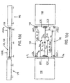
- the Reaction Force Device (RFD) system 100 measures, among many other variables, the weight and forces related to walking gait of animals.
- the RFD system 100 has a walk-through layout configured to guide the animals through the RFD one at a time. As the animal passes through the RFD system, stepping on instrumented plates, the animal's limb reaction forces, weight, bilateral symmetry of limb reaction forces, and other factors may be determined, as discussed below. Once one animal has passed through the RFD system, another animal may then enter the RFD system.
- the RFD system is particularly suited to applications wherein a plurality of animals, such as a herd of cattle, are sequentially enter the system to determine the presence of lameness in any particular individual in the group.
- impediments to animal movement may be provided.
- impediments include an initial step-up 110, side railings 115 (shown only on one of two sides in Figure 1(a) ) or side walls that constrain the animal's lateral movement to thereby force the animal to walk over the plate, and a divider 125 the prompts the animal to place its left leg on a left plate 130 and right foot on a right plate 120 or prevents the animal from placing its left leg on a left plate 130 and right foot on a right plate 120.
- the step-up 110 dimensions are 127 cm x 122 cm x 18 cm (width, length and height), although these dimensions may be freely varied to accomplish the intended result.
- the step-up 110 is configured to compel the animals to space themselves and walk through the system one at a time.
- the left and right floor plates 130, 120 are each made of three layers comprising a 3/16" steel floor grating covered with 1/8" sheet steel and a top surface comprising an anti-slip, corrosion-resistant flooring.
- the gratings may be, for example, SGW gratings manufactured by McNichols Corporation of Tampa, Florida and the anti-slip flooring may be 1/8" Chemplate made by Chemgrate Corporation of Woodinville, WA.
- each plate 130, 120 is 63 cm in width and 198 cm in length, as shown in the central portion of Figure 1(a) .
- divider 125 is approximately 1 cm in width, yielding the total width of 127 cm.
- a length inclusive of at least 3 ⁇ of the distance traversed by the sample population at the desired gait is multiplied by a factor such as two, three, or more to obtain multiples of individual limb contact data with the first and second plates 130, 120.
- more than two plates 130, 120 may be used in accord with the invention.
- another set of plates, a second left plate and a second right plate could be provided after the first left plate 130 and first right plate 120.
- a fore force plate and a hind force plate could be provided to detect differences in an animal's stance and force distribution between fore limbs and rear limbs.
- Partition or divider 125 projects upwardly from an inner edge of one of the left and right plates 130, 120 or a position between the left and right plates.
- This divider 125 in a preferred aspect of the invention, is a single continuous divider having a width of about 1 cm and a height of between about 0.5 to 1.5 cm. The width and the height may vary in accord with a size of the animal, but is preferred not to exceed a height of about 3 cm. The inventors have determined that barrier 125 heights above 3 cm start to affect the animal's normal cadence, thus potentially reducing the amount of or value of the data obtained.
- the height of barrier 125 may exceed 3 cm if the specific data desired to be obtained is not related to or dependent on the animal's cadence and limb cross-over is itself a concern.
- the divider 125 may comprise a rigid or semi-rigid material, such as a plastic or resilient rubber, and may preferably be rounded at the edges.
- a partition or divider 125 is not required, however, as limb-cross over is uncommon and may be corrected by an additional run of the animal through the RFD or by intervention by the RFD user in the data analysis to back out the values of the left limb and right limb, respectively.
- each plate 130, 120 is supported by an array of four load cells 150 distributed adjacent the four corners of the respective plate 130, 120.
- the invention may comprise more or less load cells 150 distributed in various locations and arrangements above, below, or adjacent the plates 130, 120 in accord with the physical configuration and type (e.g., number of axes) of load cell selected and the desired robustness of data.
- X is positive in a direction toward the outside of the plates
- Y is positive in a direction of the rear or backside of the plates
- Z is positive in an upward direction.
- the position of a force applied to the plates 130, 120 is thus defined through the left and right coordinate systems (X L , Y L and X R , Y R ) shown Figures 1(a) and 1(c) .
- the RFD system 100 calculates the position of that limb.
- the RFD system 100 calculates the position of an equivalent or resultant force, as discussed below.
- a suitable load cell for this arrangement is Model RL35083 produced by Rice Lake Weighing Systems of Rice Lake, Wisconsin. If a greater or lesser number of load cells 150 is desired, correspondingly and respectively decreasing or increasing the Ground Reaction Force (GRF) experienced by any individual load cell 150, alternative load cells may be selected to appropriately maintain the GRFs within the calibrated working ranges of each load cell. For applications involving cows, the inventors have determined that the GRFs are substantially vertical and GRF variations due to lameness, or the onset thereof, are determinable based on differences in these vertical GRFs. Therefore, bovine applications may employ a plurality of single-axis load cells measuring force in only the vertical direction, thus achieving a significant cost reduction over comparable multi-axis system.
- GRF Ground Reaction Force
- the present invention also includes applications utilizing multi-axis load cells such as 2-axis, 3-axis, and n-axis load cells, where n is any integer, in any number and any combination.
- multi-axis load cells such as 2-axis, 3-axis, and n-axis load cells, where n is any integer, in any number and any combination.
- n is any integer, in any number and any combination.
- a lesser number of multi-axis load cells 150 could be used in lieu of the four single-axis load cells of the embodiment described above for a bovine application.
- an equal number or greater number of such multi-axis load cells could be used, just as the number of single-axis load cells could be increased, as desired.
- Some embodiments of the present invention could, for example, advantageously utilize one or more load cells 150 per left or right plate 130, 120, wherein the load cell 150 is able to measure three orthogonal force components along the X, Y, and Z axes, as well as the moments about the axes, producing up to six outputs.
- These multi-axis load cells are particularly useful for measuring GRF components of hoof or foot movement in a plurality of axis, but may be also used to reduce the number of load cells required for an RFD, such as an RFD configured for a bovine application, by replacing the 4 single-axis load cells with two 3-axis load cells for each of the left and right plates 130, 120.
- the load cell 150 specifications and arrangements may be freely varied and optimized to identify ailments endemic to a particular animal type based on the physical manifestation of such ailment on the GRFs produced by the animal's hoof or foot against a load sensitive surface 130, 120.
- the load cells 150 and left and right plates 130, 120 are mounted on a single base.
- the load cell 150 outputs are sampled by an A/D board 950, such as an Iotech DaqBook model 200, receiving signals from an external eight channel strain gage module 970, such as an lotech DBK43A. These eight channels are read sequentially through a single channel amplifier 960 and the sampled data is stored in computer memory 906, 910 in a convenient computer readable medium, such as an ASCII file.
- the sampling rate of the A/D board is preferably set to 100 Hz, but may be increased in accord with frequency of the sampled events to provide an appropriate sampling rate, such as a sampling rate greater than the Nyquist rate, as known to those skilled in the art.
- a ramp down 140 is disposed immediately after the left and right plates to permit egress of the animal from the RFD system 100.
- a suitable ramp down possesses a width of 127 cm and a length of 122 cm, although these dimensions may vary significantly in accord with space constraints, if any. Generally, the downgrade is maintained between about 5 to 15' to avoid injury to the animals.
- the ramp 140 preferably comprises the same layered structure as the left and right floor plates 130, 120. Alternatively, some animals, such as horses do not respond well to such ramps, steps, or height differences. Therefore, another embodiment of the invention advantageously incorporates the left and right floor plates 130, 120 into the floor itself so that the upper surface of the floor plates 130, 120 are substantially flush with the remainder of the floor surface.
- a plurality of photocells, and corresponding reflective elements, may be disposed to measure each animals' speed through the RFD system 100.
- three photocells 160 are sequentially arranged along the left or right plates 130, 120 so as to be triggered by the cow's brisket and rear flank as the cow passes though the line of sight of one of the three sequentially spaced photo-cells. Any number of photocells could be used in accord with the invention, however. Additionally, it is generally preferred that the photocells 160 be spaced along the entire length of the plates 130, 120, or may be grouped toward the center or toward one side in accord with the invention.
- the RFD system 100 is calibrated by placing a known or calibrated weight at predetermined (X. V) positions along each of the left and right plates 130, 120 and recording the voltage produced by the individual load cells 150.
- the weights may be 113.2 kg, 158.6 kg, and 203.8 kg.
- the reaction force at each of the eight load cells 150 is evaluated, in one preferred aspect of the invention, via one or more finite element models (FEM), known to those skilled in the art, when the unit loads are applied at the left and right calibration points C L and C R .
- FEM finite element models
- Alternative calculation methods known to those skilled in the art may also be used to determine the reaction forces.
- Lines that pass through the zero load conditions and best fit, using conventional best fit techniques, to the three applied known loads establish the loading factors of the eight individual load cells 150.
- the calibration factors of the load cells 150 are calculated as a ratio of the computed applied loads to the individual load cell 150 readings. These factors, listed in Table 1 below, are stored computer 900 for later use by the calibration program.
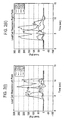
- load cell 150 reactions to the cow's passage are recorded as a function of time (see Figures 2(i) and 2(ii) ) while the aforementioned array of photocells 160 measures the walkthrough speed ( Figure 2(iii) ). Summation of load cell 150 reactions provides an accurate measurement of the cow's body weight. As shown in Figure 2(iv) , for example, the body weight of cow 18 is determined to be 672.7 Kg.
- the load cell 150 reactions are used to calculate the X and Y coordinates of the cow's limb positions and the associated left and right Ground Reaction Forces (GRF), previously mentioned.
- GRF Ground Reaction Forces
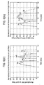
- the time history of the X and Y limb positions and the left and right GRF values for a sound cow that has passed through the device are depicted in Figure 3 .
- the X and Y limb positions and the GRF values, shown in Figure 3 are used to calculate various limb movement variables, as discussed in greater detail below. These limb movement variables are analyzed to objectively determine whether an animal, such as a cow, has hoof, foot, or leg ailments.
- limb movement variables are the key to identifying lame animals and detecting which limb of an animal is afflicted with an ailment well before the ailment is manifested in a manner detectable by purely visual observation of the animal's movement
- the limb movement variables are calculated by analyzing the X, Y and GRF values and the walking speed of each animal passing through the RFD system 100.
- FIG. 6 and 7 Examples of the usefulness of these limb movement variables are illustrate in Figures 6 and 7 .
- a full set of leg positions, X and Y values, and ground reaction forces, GRF values are plotted in Figure 6 for a healthy cow and in Figure 7 for a lame cow.
- the identification of the time, position, and intensity of individual front and rear limb contact with the left and right plates 130, 120 is premised, in part, on the fact that the left and right forelimbs strike the plate first and the hind limbs follow behind. Using this premise, the sequence by which the animal's limbs contacted the plates 130, 120 may be determined.
- Photocell 160 data is used to confirm the position of the cow and to verify that only one cow is on the force plates 130, 120.
- Limb movement variables, provided below, may be calculated when a single leg is in contact with the left or right plate or even when two limbs are in contact with a single plate.
- the typical RFD output consists of both single and two limb positions
- the stance time may be computed for a fore limb, a rear limb, or for both a fore and rear limb, or for all limbs.
- the total time that a limb is in contact with the left or right plate 130, 120 may be calculated by taking a difference between a first time at which an applied force from the selected limb first exceeds a predetermined threshold force as the limb is applied to the plate and a second time at which the applied force from the limb falls below the predetermined threshold force.
- the predetermined threshold is simply a force that is used as a trigger to start and stop the computation of the stance time.
- the preselected force is generally between 0.00 to about 5.0 lbf, but could be 10.0 lbf, 20.0 lbf, or higher, so long as a consistent value is used.
- limb movement variables of sound cow 18 are listed in Table 2, below. Table 2.
- Cow Limb Movement Variables Individual Limbs Left Front [LF] Right Front [RFD] Left Rear [LR] Right Rear [RR] Sound 18 Normalized PGRF 0.54 0.55 0.41 0.39 Stance time (sec) 2.30 1.95 1.70 1.65 Impulse (sec) 0.88 0.71 0.52 0.45 Normalized AGRF 0.38 0.37 0.31 0.27
- Step size (cm) 99 101 115 101 Speed of animal (cm/sec) 43 43 43 46 Impulse * Speed (cm) 38 31 23 21
- Figure 7 depicts the Y coordinate and normalized GRF of a cow (lame cow 94) that is known to be lame as a result of sole bruising in her right rear limb.
- limb movement variables can be used to evaluate the symmetry characteristics of the animal movement (e.g., walking, trotting, running, etc.) parameters.
- Figure 9 depicts the test results as normalized PGRF and symmetry factor bar charts.
- Figure 9(i) depicts the normalized PGRF values of sound cows (cows 18, 130, and 136), wherein the typical values of 0.5 for the front limbs and 0.4 for the rear.
- the corresponding PGRF values for the three lame cows (cows 94, 113, and 982), shown in Figure 9(ii) are 0.12 (right rear limb), 0.24 (left rear limb), and 0.25 (right rear limb).
- Figure 9(iii) and 9(iv) further depict the symmetry factors of the front and rear limbs.
- the SF values for the sound cows 18, 130, and 136 are better than 0.07
- the SF values of cows 94, 113, and 982 are -0.61, 0.33, and -0.30, respectively.
- various conventional lameness detection schemes employ visual observations of the animal's posture or gait to obtain relatively assign a value corresponding to the severity of the lameness.
- the present invention advantageously determines various limb movement characteristics through the RFD system.
- the RFD system can be used to measure multiple variables representative of limb movements, such as: (a) peak value of ground reaction force (GRF) of individual limbs, (b) integral of GRF with respect to time, (c) stance time, (d) average GRF, (e) step size, (f) integral of the Fourier transformation of the GRF signature with respect to frequency, and (g) the integral with respect to frequency of the Fourier transform of the GRF signature multiplied by the frequency, (h) various symmetry variables, and numerous other combinations, derivatives, and integrals.
- the variables representative of limb movements may be normalized with respect to body weight and symmetry variables may be used to compare left to right limbs for the same speed of body movement.
- the limb movement variables can be used to evaluate the symmetry characteristics of the animal walking parameters, for example, the limb movement variables may be advantageously used to actually relate clinical lameness diagnoses of individual limbs to the measured values of limb movement variables.
- the conventional techniques utilize subjective and non-quantitative visual observation.
- a statistically sufficient sample population of a selected animal such as a dairy cow or horse, for example, is evaluated using the RFD to obtain limb movement variables for each animal. Subsequent to or preceding the RFD testing on the sample population, a determination is made by a veterinarian or other person trained to diagnose lameness, or other ailment or condition manifesting in the animal's movement.
- correlations may be drawn between individual limb variables or combinations of limb variables such as but not limited to any data manipulation, such as but not limited to products, sums, differences, dividends, derivatives, integrals, log charts, etc., conventionally used to relate data to definable patterns used to then generate a function to describe an observed phenomena such that a function of one or more variables may be established between the limb movement data, limb movement variables, and/or combinations thereof, and lameness, for example.
- additional RFD tests e.g., a "subsequent" test
- This subsequent test may be used to validate or confirm the results of the first test, particularly when the first test indicates the onset of a potential problem with the animal.
- the invention is not limited to simple determinations of "sound” or “lame”, but is capable of measuring and defining many levels or degrees of lameness, which facilitates early detection of potential lameness precursors and thereby promotes animal well-being.
- inventors have performed logistic regression and discriminant analyses, such as by LOGISTICTM, STEPDISCTM, and SASTM computer program subroutines, known to those skilled in the statistical analysis art, to determine a strong correlation between the visual lameness scoring scale and the GRFs determined by the apparatus of the invention.
- the correlation between the visual lameness scoring scale and the GRFs can be captured by the average GRF values (p ⁇ 0.05), or in other words, a 95% confidence level, of individual limbs.
- the model or formulas generatable therefrom such as but not limited to an estimated lameness index derived as the weighted sum of these probabilities, predict probabilities that a cow is sound, mildly lame, and lame.
- the models or formulas generated from the data obtained by the RFD system may include many degrees of lameness, or other observed characteristic, in accord with a statistically significant sample size. For example, 5 degrees of lameness, or even 10 or more degrees of lameness may be gleaned from sufficient data samples.
- the inventors have determined, with respect to a small sample size of 16 mildly lame and sound dairy cows, that the diagnostic results of the visual scoring scale and the new estimated lameness index matched perfectly for lame cows and the visual scores and lameness index of 2 out of 16 mildly lame and sound cases exhibited discrepancies.
- the limb movement data, limb movement variables, and mathematically manipulated combinations or variations thereof can be used to develop objective measures of dairy cow lameness in combination with existing clinical lameness diagnoses of individual limbs.
- limb movement data can be used to develop many other objective measures of dairy cow lameness or other characteristics of interest in combination with existing clinical lameness diagnoses of individual limbs and these objective measures could include many levels of severity or interest.
- models for an ailment such as lameness, as varying degrees of severity thereof, may be developed for specific animal-types based on the data obtained by the RFD.
- Such models could thus determine the lameness score of individual limbs based on the values of a set of important limb movement variables and could account for many environmental variables such as geographic location, climate, living conditions, and even farm management styles.
- the RFD system following development of correlations between the raw data and/or derived data, as noted above, obtained from the RFD system, the RFD system can be largely or entirely automized.
- an RFD system could be placed in a tract that the animals pass through with a frequency commensurate with at least a desired diagnostic frequency and the system may be set up and calibrated in advance.
- trending data of the RFD system calibration may be used to determine whether or not a particular application or environment of the RFD system would permit re-calibrations at a frequency less than the diagnostic test frequency.
- one aspect of the invention includes a means for identification or labeling of the animal for subsequent follow-up by veterinarian.
- one or more dye markers, ink jets, or other marking device may provided at the exit of the RFD to place a temporary mark on an animal as it exits the RFD system. These dye markers, or other marking devices, may place a temporary colored mark on the animal's hide to designate the occurrence of an ailment. Various colors could also be used as an indicator of severity.
- an imaging system could be used to image the animal or a part thereof, such as a conventional location of a brand or marking or ear tag and store the information on the computer memory or transmit the information to a remote location.
- the animals may be equipped with electronic memory devices or data tags, such as but not limited to those manufactured by SanDisk Corp. of Sunnyvale, Calif.
- Such devices typically encapsulated, utilize semiconductor memory devices or chips to store information and an antenna to send and receive data in the form of radio or high-frequency signals.
- the RFD system computer, or other device could read the memory of an animals data tag using, for example, radio signals or high-frequency signals.
- Detailed testing information as described above, may be output to and stored in such "local" memory to facilitate trending of limb movement data, or other variables, such as but not limited to weight. In such a configuration, the system would perform a read operation on the animal's data tag upon entry of the animal into the RFD.
- the animal's previous test data could be uploaded into the RFD computer and, following the movement of the animal through the RFD, could be compared to the current test data in various manners such as, but not limited to, those described above.
- current test data could overwrite or supplement the previous test data in accord with data tag memory requirements.
- the data tag may be advantageously used to simply store the results of previous test results. For example, if lameness is being detected and there is a 10-level severity scale, the date of a test and the severity on the 10-level scale could be saved in the data tag memory. In a subsequent test, that data could be retrieved to facilitate data analysis and trending in view of the new test results.
- the tags may be read from and written to several feet away within less than one second. Naturally, if the animal receives treatment, the data tag memory could be reset or supplemented with such information.
- FIG 10 is a block diagram illustrating a conventional computer system 900 upon which an embodiment of the invention may be implemented.
- Computer system 900 includes a bus 902 or other communication mechanism for communicating information, and a processor or processors 904 coupled with bus 902 for processing information.
- Computer system 900 also includes a main memory 906, such as a random access memory (RAM) or other dynamic storage device, coupled to bus 902 for storing information and instructions to be executed by processor 904.
- Main memory 906 also may be used for storing temporary variables or other intermediate information during execution of instructions to be executed by processor 904.
- Computer system 900 further includes a read only memory (ROM) 908 or other static storage device coupled to bus 902 for storing static information and instructions for processor 904.
- ROM read only memory
- a storage device 910 such as a magnetic disk or optical disk, is provided and coupled to bus 902 for storing information and instructions.
- Computer system 900 may be coupled via bus 902 to a display 912, such as a cathode ray tube (CRT), for displaying information to a computer user.
- a display 912 such as a cathode ray tube (CRT)
- An input device 914 is coupled to bus 902 for communicating information and command selections to processor 904.
- cursor control 916 is Another type of user input device
- cursor control 916 such as a mouse, a trackball, or cursor direction keys for communicating direction information and command selections to processor 904 and for controlling cursor movement on display 912.
- This input device typically has two degrees of freedom in two axes, a first axis (e.g., x) and a second axis (e.g., y), that allows the device to specify positions in a plane.
- Computer system 900 is used to process all GRF data obtained by the various load cells by means of the calibration program and data acquisition software and converts the force data, using equations and principles discussed herein, into usable data.
- the pertinent programs and executable code is contained in main memory 906 and is selectively accessed and executed in response to processor 904, which executes one or more sequences of one or more instructions contained in main memory 906.
- Such instructions may be read into main memory 906 from another computer-readable medium, such as storage device 910.
- processors in a multi-processing arrangement may also be employed to execute the sequences of instructions contained in main memory 906.
- hard-wired circuitry may be used in place of or in combination with software instructions and it is to be understood that no specific combination of hardware circuitry and software are required.
- the instructions may be provided in any number of forms such as source code, assembly code, object code, machine language, compressed or encrypted versions of the foregoing, and any and all equivalents thereof.
- Computer-readable medium refers to any medium that participates in providing instructions to processor 904 for execution and "program product” refers to such a computer-readable medium bearing a computer-executable program.
- the computer usable medium may be referred to as "bearing" the instructions, which encompass all ways in which instructions are associated with a computer usable medium.
- Computer-readable mediums include, but are not limited to, non-volatile media, volatile media, and transmission media.
- Non-volatile media include, for example, optical or magnetic disks, such as storage device 910.
- Volatile media include dynamic memory, such as main memory 906.
- Transmission media include coaxial cables, copper wire and fiber optics, including the wires that comprise bus 902. Transmission media may comprise acoustic or light waves, such as those generated during radio frequency (RF) and infrared (IR) data communications.
- RF radio frequency
- IR infrared
- Computer-readable media include, for example, a floppy disk, a flexible disk, hard disk, magnetic tape, any other magnetic medium, a CD-ROM, DVD, any other optical medium, punch cards, paper tape, any other physical medium with patterns of holes, a RAM, a PROM, and EPROM, a FLASH-EPROM, any other memory chip or cartridge, a carrier wave as described hereinafter, or any other medium from which a computer can read.
- Various forms of computer readable media may be involved in carrying one or more sequences of one or more instructions to processor 904 for execution.
- the instructions may initially be borne on a magnetic disk of a remote computer.
- the remote computer can load the instructions into its dynamic memory and send the instructions over a telephone line using a modem.
- a modem local to computer system 900 can receive the data on the telephone line and use an infrared transmitter to convert the data to an infrared signal.
- An infrared detector coupled to bus 902 can receive the data carried in the infrared signal and place the data on bus 902.
- Bus 902 carries the data to main memory 906, from which processor 904 retrieves and executes the instructions.
- the instructions received by main memory 906 may optionally be stored on storage device 910 either before or after execution by processor 104.
- Computer system 900 may also include a communication interface 918 coupled to bus 902 to provide a two-way data communication coupling to a network link 920 connected to a local network 922.
- communication interface 918 may be an integrated services digital network (ISDN) card or a modem to provide a data communication connection to a corresponding type of telephone line.
- ISDN integrated services digital network
- communication interface 918 may be a local area network (LAN) card to provide a data communication connection to a compatible LAN.
- LAN local area network
- Wireless links may also be implemented.
- communication interface 918 sends and receives electrical, electromagnetic or optical signals that carry digital data streams representing various types of information.
- Network link 920 typically provides data communication through one or more networks to other data devices.
- network link 920 may provide a connection through local network 922 to a host computer 924 or to data equipment operated by an Internet Service Provider (ISP) 926.
- ISP 926 in turn provides data communication services through the worldwide packet data communication network, now commonly referred to as the "Internet" 928.
- Internet 928 uses electrical, electromagnetic or optical signals that carry digital data streams.
- the signals through the various networks and the signals on network link 920 and through communication interface 918, which carry the digital data to and from computer system 900, are exemplary forms of carrier waves transporting the information.
- the processing required by method of the invention described by way of example herein may be implemented on a local computer utilizing storage device 910 or may be implemented, for example, on a LAN or over the internet.
- Computer system 900 can send messages and receive data, including program code, through the network(s), network link 920, and communication interface 918.
- a server 930 might transmit a requested code for an application program through Internet 928, ISP 926, local network 922 and communication interface 918.
- the received code may be executed by processor 904 as it is received, and/or stored in storage device 910, or other non-volatile storage for later execution. In this manner, computer system 900 may obtain application code in the form of a carrier wave.
Landscapes
- Life Sciences & Earth Sciences (AREA)
- Health & Medical Sciences (AREA)
- Engineering & Computer Science (AREA)
- Medical Informatics (AREA)
- Biophysics (AREA)
- General Health & Medical Sciences (AREA)
- Surgery (AREA)
- Environmental Sciences (AREA)
- Oral & Maxillofacial Surgery (AREA)
- Veterinary Medicine (AREA)
- Public Health (AREA)
- Pathology (AREA)
- Dentistry (AREA)
- Biomedical Technology (AREA)
- Heart & Thoracic Surgery (AREA)
- Molecular Biology (AREA)
- Physics & Mathematics (AREA)
- Animal Behavior & Ethology (AREA)
- Radiology & Medical Imaging (AREA)
- Optics & Photonics (AREA)
- Nuclear Medicine, Radiotherapy & Molecular Imaging (AREA)
- Animal Husbandry (AREA)
- Biodiversity & Conservation Biology (AREA)
- High Energy & Nuclear Physics (AREA)
- Measurement Of The Respiration, Hearing Ability, Form, And Blood Characteristics Of Living Organisms (AREA)
- Investigating Or Analysing Biological Materials (AREA)
Description
- This invention relates to apparatus for detecting lameness in animals and promoting animal well-being. Particularly for detecting lameness in four legged animals, such as but not limited to houses, dairy cow, non-dairy cows, pigs, and sheep.
- Dairy production is an important industry in the U.S. and a major branch of agriculture in many countries around the world. Cow lameness caused by hoof and leg ailments is a costly problem for the dairy farmer. Lameness necessitates medical treatment, reduces milk production, results in decreased body condition, impairs reproduction performance, and adversely impacts the social status of animals. Economically, lameness is reported to be the third most costly problem for dairy herds following mastitis and sub-fertility. The average cost of lameness is reported to be 412 dollars per incident and the annual incidence rate in the U.S. is fifteen percent. Thus, the annual economic losses due to lameness is over 570 million dollars for the over nine million U.S. cows. These losses significantly impair dairy farms and harm the entire bovine industry.
- In addition to the economic impact, lameness is also recognized as an important animal welfare issue. The 1993-94 Annual Report of the Animal Welfare Foundation of the British Veterinary Association states that "... if it were possible to substantially reduce the incidence of lameness, this single initiative, more than any other would benefit more animals than any other (initiative) ...." Thus, researchers have focused on developing a means of detecting hoof and leg ailments at their early onset.
- Lameness in dairy herds has been reported to be a critical economic factor and a vital animal-welfare issue for the dairy industry around the world. Various lameness evaluation schemes that assess the severity of the ailment, using non-clinical personal, have been suggested. These schemes are based on visual observations of individual cattle. In one scheme, lameness scoring is based on the shape of the cow's back both as the animal stands and as the animal walks. However, although this scheme lends itself to field use, its results are highly subjective and are non-quantitative in nature.
- There are reports of management programs to control lameness and studies of the housing factors that influence the locomotion of dairy cows. Some of the etiological factors contributing to lameness are nutrition, bacterial and fungal infections, bacterial endotoxin, environmental conditions, housing, flooring, feeding management, and cow behaviors. The fact that many different factors lead to lameness makes it almost impossible to eliminate hoof and leg ailments and imposes difficulties for diagnostic procedures. Early detection of hoof and leg ailments is not a yet reality and most farmers record an incidence of lameness only at the stage when the cow is crippled. Thus, there is a need in the art for a method and an apparatus able to provide early detection of hoof and leg problems, which will enable prompt veterinarian medical intervention to reduce economic losses, lessen the pain that the animal endures, and expedite the animal's recovery process. Furthermore, an early detection system will facilitate scientific testing of management programs designed to reduce the rate of incidence of lameness in dairy herds and will promote animal well-being.
- A research effort that analyzes the gait of horses and detects lame limbs is reported in Schamhardt, H.C. and Merkens, H.W., "Objective determination of ground contact of equine limbs at the walk and trot: comparison between ground reaction forces, accelerometer data and kinematics, Equine Vet. J Suppl. No. 17, pp. 75-79,1994. In this study, the animal is led over a single force plate and a Horse ("H") index is calculated. However, this method and apparatus only detected the force of one of the animal's limbs. To obtain forces from each of the animal's limbs, four separate tests would have to be performed. Therefore, even though a set of forces could be obtained for each limb, such data was merely a compilation of four or more separate tests wherein the speed of the animal, as well as other variables, varied in each run. To detect lameness, the H value is compared with a previously calculated sound horse model. This type of system and index are not available for detecting lameness in dairy cows and they are not as sensitive and versatile as the system described herein. In particular, the H index relies on leading a horse multiple times across a measuring device under the assumption that the speed of the horse remains constant during all measurements.
-
US patent 5299454 discloses continuous foot-strike measurement for a human treadmill, with multi-sensor plates whose forces may be summed. -
US patent 4195643 discloses a diagnostic force analysis system for lameness in horses, measuring heel strike forces on multiple plates. -
US patent 5623944 discloses using sensors in a human treadmill and on shoes to determine gait during walking or running. - The invention provides a system as defined in
Claim 1. -
-
Figure 1(a) is a schematic representation of Reaction Force Detection (RFD) system of the present invention showing a partial side view of the RFD system including a step up; force-detecting floor plates, and ramp down. -
Figure 1 (b) is an isometric view of a force plate used in the present invention and an applied load. -
Figure 1(c) is a top down view of the RFD system including a step up, force-detecting floor plates, and ramp down of the present invention. -
Figures 2(i)-2(iv) are graphs depicting the load cell reactions of the left and right plates plotted as a function of time ((i) and (ii)), the animal's walkthrough speed as measured by a photo cell array (iii), and the animal's body weight calculated by summing the load cell reactions (iv). -
Figures 3(i)-3(iv) are charts showing the accuracy of body weight measurements, whereinFigures 3(i) and 3(ii) illustrate weight readings of the left and right plate when a weight of 203.8 Kg is placed at five points along the line X=18.4 cm and the percentage errors of these measurements for the left and right plates inFigures 3(iii) and 3(iv) , respectively. -
Figures 4(i)-4(vi) are graphs illustrating a typical time history of X (Figures 4(i) and 4(ii) ) and Y (Figures 4(iii) and 4(iv) ) coordinates of the cow's limb positions when passing through the RFD unit. Corresponding ground reaction forces are depicted inFigures 4(v) and 4(vi) . -
Figures 5(i)-5(iv) are graphs showing the accuracy of the X and Y coordinates of the limb positions. -
Figures 6(i)-6(iv) are graphs showing the time history of the Y coordinate of a sound cow's limb positions on the left and right plates (Figures 6(i) and 6(ii) , respectively) and the corresponding normalized ground reaction forces (GRF)(Figures 6(iii) and 6(iv) , respectively) obtained by dividing the GRF by the animal's body weight. -
Figures 7(i)-7(iv) are graphs showing the time history of the Y coordinate of a lame cow's limb positions on the left and right plates (Figures 7(i) and 7(ii) , respectively) and the corresponding normalized ground reaction forces (Figures 7(iii) and 7(iv) , respectively). -
Figures 8(a)-8(f) are graphs showing the Y-positions of the limbs on the left plate (a) and right plate (b), as well as the distributions of an equivalent GRF for two-limb conditions (c and d) and distributions of equivalent GRF to individual limbs (e and f). -
Figures 9(a)-9(d) are bar charts showing normalized peak ground reaction force (PGRF) for sound cows and for lame cows (Figures 9(a) and9(b) , respectively) and Symmetry Factors of sound cows and lame cows. -
Figure 10 depicts a computer-based system upon which the invention may be implemented. -
Figure 11 illustrates limb movement variables of individual limbs of two sound cows calculated in accord with the apparatus and method of the invention. -
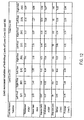
Figure 12 illustrates limb movement variables of individual limbs of two lame cows calculated in accord with the apparatus and method of the invention. - The Reaction Force Device (RFD)
system 100 measures, among many other variables, the weight and forces related to walking gait of animals. TheRFD system 100 has a walk-through layout configured to guide the animals through the RFD one at a time. As the animal passes through the RFD system, stepping on instrumented plates, the animal's limb reaction forces, weight, bilateral symmetry of limb reaction forces, and other factors may be determined, as discussed below. Once one animal has passed through the RFD system, another animal may then enter the RFD system. Thus, the RFD system is particularly suited to applications wherein a plurality of animals, such as a herd of cattle, are sequentially enter the system to determine the presence of lameness in any particular individual in the group. - To facilitate sequential movement of a plurality of animals, impediments to animal movement may be provided. In a preferred aspect of the invention, impediments include an initial step-
up 110, side railings 115 (shown only on one of two sides inFigure 1(a) ) or side walls that constrain the animal's lateral movement to thereby force the animal to walk over the plate, and adivider 125 the prompts the animal to place its left leg on aleft plate 130 and right foot on aright plate 120 or prevents the animal from placing its left leg on aleft plate 130 and right foot on aright plate 120. In a preferred aspect, the step-up 110 dimensions are 127 cm x 122 cm x 18 cm (width, length and height), although these dimensions may be freely varied to accomplish the intended result. The step-up 110 is configured to compel the animals to space themselves and walk through the system one at a time. - Following the step-
up 110, animals moving through the RFD system next encounter a floor comprising parallel left and right portions orplates partition 125 projecting upwardly from a position between the left and right plates, as shown inFigures 1(a) through 1(c) . In a preferred aspect, the left andright floor plates - In a preferred aspect, such as for a bovine application, each
plate Figure 1(a) . As illustrated inFigure 1(a) ,divider 125 is approximately 1 cm in width, yielding the total width of 127 cm. In an application of the RFD system to horses, for example, it is generally desirable to have a force plate length of between about 300 and 500 cm, although longer force plate lengths could certainly be utilized. It has been determined, however, that if the plate is too small, such as 36 cm x 52 cm, data collection of the ground reaction forces (GRFs) for bovines and animals of like gait becomes increasingly difficult, necessitating multiple passes through the system to obtain GRFs for all limbs. Therefore, although the size and number of the plates may be varied in accord with the invention, such variation must permit measurement of the GRFs for all four of the animals limbs in a single pass of the animal through the RFD. This may be accomplished, for example, by sampling the walking gait or other gait such as a trot or run, of a sample population of the animals and determining the distance traversed by the animals at that gait to a desired statistical significance. In one aspect of the invention, it is preferred to use a length inclusive of at least 3σ of the distance traversed by the sample population at the desired gait. In another aspect of the invention, the above length is multiplied by a factor such as two, three, or more to obtain multiples of individual limb contact data with the first andsecond plates plates left plate 130 and firstright plate 120. Alternatively, prior to or subsequent to theinitial plates - Partition or
divider 125 projects upwardly from an inner edge of one of the left andright plates divider 125, in a preferred aspect of the invention, is a single continuous divider having a width of about 1 cm and a height of between about 0.5 to 1.5 cm. The width and the height may vary in accord with a size of the animal, but is preferred not to exceed a height of about 3 cm. The inventors have determined thatbarrier 125 heights above 3 cm start to affect the animal's normal cadence, thus potentially reducing the amount of or value of the data obtained. However, in accord with the invention, the height ofbarrier 125 may exceed 3 cm if the specific data desired to be obtained is not related to or dependent on the animal's cadence and limb cross-over is itself a concern. In a preferred embodiment of thedivider 125 may comprise a rigid or semi-rigid material, such as a plastic or resilient rubber, and may preferably be rounded at the edges. A partition ordivider 125 is not required, however, as limb-cross over is uncommon and may be corrected by an additional run of the animal through the RFD or by intervention by the RFD user in the data analysis to back out the values of the left limb and right limb, respectively. - As shown by the embodiment of
Figure 1(c) , eachplate load cells 150 distributed adjacent the four corners of therespective plate less load cells 150 distributed in various locations and arrangements above, below, or adjacent theplates - These
load cells 150 measure the ground reaction forces (GRFs) produced as the animal steps on each plate. TheRFD system 100 measures these ground reaction forces and calculates the position of the weight placed on therespective floor plate Figure 1(c) , each of theplates plates plates Figures 1(a) and1(c) . When a single limb (i.e., hoof or foot) is on aplate RFD system 100 calculates the position of that limb. When more than one limb is in contact with afloor plate RFD system 100 calculates the position of an equivalent or resultant force, as discussed below. - A suitable load cell for this arrangement is Model RL35083 produced by Rice Lake Weighing Systems of Rice Lake, Wisconsin. If a greater or lesser number of
load cells 150 is desired, correspondingly and respectively decreasing or increasing the Ground Reaction Force (GRF) experienced by anyindividual load cell 150, alternative load cells may be selected to appropriately maintain the GRFs within the calibrated working ranges of each load cell. For applications involving cows, the inventors have determined that the GRFs are substantially vertical and GRF variations due to lameness, or the onset thereof, are determinable based on differences in these vertical GRFs. Therefore, bovine applications may employ a plurality of single-axis load cells measuring force in only the vertical direction, thus achieving a significant cost reduction over comparable multi-axis system. - However, the present invention also includes applications utilizing multi-axis load cells such as 2-axis, 3-axis, and n-axis load cells, where n is any integer, in any number and any combination. For example, a lesser number of
multi-axis load cells 150 could be used in lieu of the four single-axis load cells of the embodiment described above for a bovine application. Alternatively, an equal number or greater number of such multi-axis load cells could be used, just as the number of single-axis load cells could be increased, as desired. Some embodiments of the present invention could, for example, advantageously utilize one ormore load cells 150 per left orright plate load cell 150 is able to measure three orthogonal force components along the X, Y, and Z axes, as well as the moments about the axes, producing up to six outputs. These multi-axis load cells are particularly useful for measuring GRF components of hoof or foot movement in a plurality of axis, but may be also used to reduce the number of load cells required for an RFD, such as an RFD configured for a bovine application, by replacing the 4 single-axis load cells with two 3-axis load cells for each of the left andright plates load cell 150 specifications and arrangements may be freely varied and optimized to identify ailments endemic to a particular animal type based on the physical manifestation of such ailment on the GRFs produced by the animal's hoof or foot against a loadsensitive surface - In the above described aspect of the invention, the
load cells 150 and left andright plates Figure 10 , discussed in more detail below, theload cell 150 outputs are sampled by an A/D board 950, such as anIotech DaqBook model 200, receiving signals from an external eight channelstrain gage module 970, such as an lotech DBK43A. These eight channels are read sequentially through asingle channel amplifier 960 and the sampled data is stored incomputer memory - Following passage of the animal over the step-up 110 and over the left and
right plates RFD system 100. A suitable ramp down possesses a width of 127 cm and a length of 122 cm, although these dimensions may vary significantly in accord with space constraints, if any. Generally, the downgrade is maintained between about 5 to 15' to avoid injury to the animals. Theramp 140 preferably comprises the same layered structure as the left andright floor plates right floor plates floor plates - A plurality of photocells, and corresponding reflective elements, may be disposed to measure each animals' speed through the
RFD system 100. In one preferred aspect, illustrated inFigure 1(a) , threephotocells 160 are sequentially arranged along the left orright plates photocells 160 be spaced along the entire length of theplates - The
RFD system 100 is calibrated by placing a known or calibrated weight at predetermined (X. V) positions along each of the left andright plates individual load cells 150. In a preferred calibration technique, a calibrated load of 203.8 Kg is placed at (X, Y) = (18.74 cm, 99 cm). - Initial animal tests showed that a sound cow places her limbs at X values that range between 15 to 20 cm when passing through the
RFD system 100. Accordingly, a longitudinal center line at X =18.74 cm was selected as a preferred calibration point, however, any point between 15 cm and 20 cm would suffice for this application. Correspondingly, the weight of the calibration weight and the location of the center line may be adjusted in accord with the size and weight of the group of animals to be observed. The system calibration points, shown as CL and CR inFigure 1(c) , are selected along the longitudinal center lines at XL,R = 18.74 cm. To calibrate the system, it is preferred that three calibrated weights be placed on each of the left andright plates load cells 150 are measured and stored. In one aspect, the weights may be 113.2 kg, 158.6 kg, and 203.8 kg. - The reaction force at each of the eight
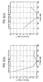
load cells 150 is evaluated, in one preferred aspect of the invention, via one or more finite element models (FEM), known to those skilled in the art, when the unit loads are applied at the left and right calibration points CL and CR. Alternative calculation methods known to those skilled in the art may also be used to determine the reaction forces. Lines that pass through the zero load conditions and best fit, using conventional best fit techniques, to the three applied known loads establish the loading factors of the eightindividual load cells 150. In other words, the calibration factors of theload cells 150 are calculated as a ratio of the computed applied loads to theindividual load cell 150 readings. These factors, listed in Table 1 below, are storedcomputer 900 for later use by the calibration program. It is preferred that the calibration procedure be performed prior to use of the RFD; however, trending analyses may advantageously be performed to determine the degree of miscalibration over time for a particular application and environment to determine the efficacy of such per-use calibrations.Table 1. Load distribution of the right and left floor plates as calculated by the finite element model and corresponding calibration factors of the system eight load cells. Load Cell Load Distribution Obtained by FEM Calibration Factors Kg/Volt LC1 0.08 0.0257 LC2 0.06 0.0111 LC3 0.44 0.0324 LC4 0.42 0.0273 LC5 0.44 0.0264 LC6 0.43 0.0260 LC7 0.07 0.0229 LC8 0.06 0.0286 - To characterize the accuracy of the measurements of the ground reaction forces and total body weight measurements, a weight of 203.8 kg is placed at five points along the lines XL,R = 18.74 cm. Each measured load and its location is measured and calculated, respectively, in a manner discussed below. Errors of the load measurements on the right and left plates have been found to be less than 1.3% and 1.7%, respectively, as shown in
Figure 3(iv) and 3(iii) , respectively. The resulting error locations along the X and Y axes in theright plate 120 were found to be less than 1.3 and 3.1 cm, respectively, and the corresponding errors in theleft plate 130 are less than 1.5 and 2.4 cm, respectively. - In the
RFD system 100,load cell 150 reactions to the cow's passage are recorded as a function of time (seeFigures 2(i) and 2(ii) ) while the aforementioned array ofphotocells 160 measures the walkthrough speed (Figure 2(iii) ). Summation ofload cell 150 reactions provides an accurate measurement of the cow's body weight. As shown inFigure 2(iv) , for example, the body weight ofcow 18 is determined to be 672.7 Kg. - Turning to the calculations executed by the
computer 900 in the analysis of the animal's walking gait and weight, theload cell 150 reactions are used to calculate the X and Y coordinates of the cow's limb positions and the associated left and right Ground Reaction Forces (GRF), previously mentioned. In these calculations, it is assumed that the right and left legs of the cow make contact with the corresponding right and leftplates plate load cells 150 associated with theleft plate 130, designated as "RLci", or the Reaction Force of each of the fourload cells 150 associated with theright plate 120, designated as "RRci", are added together to calculated the GRF for that side. These individual reaction forces and the GRF for each side are used to calculate the limb contact positions with respect to the X and Y-axes. - The X and Y limb contact positions are calculated by summing the moments in the X-axis and Y-axis directions. Specifically, the GRFR and XR and YR contact limb positions of the right plate are calculated as:


- where RLci is the reaction force read by the i-th load cell, and XLci and YLci are the X and Y coordinates of the load cells positions, as depicted in
Figure 3 . The corresponding GRF and limb positions of the left plate are calculated in a similar way: - The time history of the X and Y limb positions and the left and right GRF values for a sound cow that has passed through the device are depicted in
Figure 3 . The X and Y limb positions and the GRF values, shown inFigure 3 , are used to calculate various limb movement variables, as discussed in greater detail below. These limb movement variables are analyzed to objectively determine whether an animal, such as a cow, has hoof, foot, or leg ailments. Analysis of these limb movement variables are the key to identifying lame animals and detecting which limb of an animal is afflicted with an ailment well before the ailment is manifested in a manner detectable by purely visual observation of the animal's movement The limb movement variables are calculated by analyzing the X, Y and GRF values and the walking speed of each animal passing through theRFD system 100. - various limb movement characteristics are calculated from the information depicted in
Figure 6 . Table 2 below lists the values of non-limiting limb movement variables: - (i) normalized peak ground reaction force PRGF,
- (ii) impulse which is the integral of the normalized GRF with respect to time,
- (iii) stance time, the time during which a limb is in contact with the floor plate,
- (iv) normalized average ground reaction force AGRF which is the impulse divided by the stance time,
- (v) step size of individual limbs,
- (vi) speed of animal movement when a particular limb contacts the floor,
- (vii) the product of the impulse and cow speed which results in a characteristic unit length;
- (viii) the "m-energy", defined herein as the integral of the magnitude of the GRFs with respect to the frequency in the frequency response domain;
- (ix) the "p-energy", defined herein as the integral, over the frequency domain, of the product of the magnitude of the GRFs and frequency; and
- (x) understep of the animal, for a left side or right side of the animal, such as a horse, defined as the Y position of the fore limb placement (YFORE) minus the Y position of the hind limb placement (YHIND), wherein a positive value indicates that that the animal puts the front limb ahead of the rear limb as it moves through the RFD and wherein a negative value indicates that the animal puts the rear limb ahead of the front limb as it moves through the RFD.
- Examples of the usefulness of these limb movement variables are illustrate in
Figures 6 and7 . A full set of leg positions, X and Y values, and ground reaction forces, GRF values are plotted inFigure 6 for a healthy cow and inFigure 7 for a lame cow. The identification of the time, position, and intensity of individual front and rear limb contact with the left andright plates plates Photocell 160 data is used to confirm the position of the cow and to verify that only one cow is on theforce plates - The stance time may be computed for a fore limb, a rear limb, or for both a fore and rear limb, or for all limbs. The total time that a limb is in contact with the left or
right plate - When only one limb is in contact with the
plate computer 900 utilizing equations (1) through (6), above, and output to an appropriate output device, such asdisplay 912 or attached printer, or to a remote device throughcommunication interface 918. For example,Figure 6 shows a sound cow that has placed her right forelimb first at Y = 53 cm (Figure 6(ii)(a) ) and then her left forelimb at Y = 96 cm (Figure 6(i)(b) ). Next, the right hind limb is placed at Y = 8 cm (Figure 6(ii)(c) ) and the right forelimb was moved to Y = 155 cm (Figure 6(ii)(d) ). - Concurrent placement of both the right fore and hind limbs on the
right plate 120 is represented inFigures 6(ii) and6(iv) as "cd". Similarly, the left hind and fore limbs are then placed at Y = 46 cm and Y = 193 cm, respectively, as shown inFigures 6(i) and6(iii) . Concurrent placement of both the left fore and hind limbs on theleft plate 130 is represented as "ef". At the end of the cow's walk-through, the right and left hind limbs were placed at Y = 107 cm (Figure 6(ii)(g) ) and Y = 163 cm (Figure 6(i)(h) ), respectively. - Normalized GRF values of the sound cow's left and right limbs are depicted in
Figures 6(iii) and 6(iv) , which illustrate that the peak GRF values of the right and left fore limbs are 0.55 (seeFigure 6(iv)(a) ) and 0.54 (seeFigure 6(iii)(b) ), respectively, whereas the peaks of the right and left hind limbs are 0.39 (seeFigure 6(iv)(g) ) and 0.41 (seeFigure 6(iii)(h) ), respectively. - The numerical values selected limb movement variables of
sound cow 18 are listed in Table 2, below.Table 2. Limb movement variables of sound cow 18.Cow Limb Movement Variables Individual Limbs Left Front [LF] Right Front [RFD] Left Rear [LR] Right Rear [RR] Sound 18Normalized PGRF 0.54 0.55 0.41 0.39 Stance time (sec) 2.30 1.95 1.70 1.65 Impulse (sec) 0.88 0.71 0.52 0.45 Normalized AGRF 0.38 0.37 0.31 0.27 Step size (cm) 99 101 115 101 Speed of animal (cm/sec) 43 43 43 46 Impulse * Speed (cm) 38 31 23 21 - Similarly,
Figure 7 depicts the Y coordinate and normalized GRF of a cow (lame cow 94) that is known to be lame as a result of sole bruising in her right rear limb. As shown byFigure 7 , the lame cow first places her right front limb at Y = 46 cm (Figure 7(ii)(a) ) and left front limb at Y = 97 cm (Figure 7(i)(b) ). Subsequently the right and left rear limbs are placed at Y = 30 cm (Figure 7(ii)(c) ) and Y = 64 cm (Figure 7(i)(d) ), respectively. Then, the right front limb is placed at Y = 114 cm (Figure 7(ii)(e) ) and theright plate 120 experiences two limb contact, designated as "ce" inFigure 7(ii) . Finally, the left and right rear limbs were placed at Y = 198 cm (Figure 7(i)(g) ) and Y = 127 cm (Figure 7(ii)(f) ), respectively. The varying Y position reading (of 127 to 165 cm) when the right hind limb contacts thefloor 120 illustrates a shift in the cow's weight placement toward the toe and off the heel. - Normalized GRF values of the lame cow's left and right limbs are depicted in
Figures 7(iii) and 7(iv) , which illustrate that the peak GRF values of the right and left fore limbs are 0.47 (seeFigure 7(iv)(a) ) and 0.53 (seeFigure 7(iii)(b) ), respectively, whereas the peaks of the right and left hind limbs are 0.12 (seeFigure 7(iv)(g) ) and 0.50 (seeFigure 7(iii)(h) ), respectively. Thus, the lame right hind limb produces a noticeably low peak GRF value. - The numerical values selected limb movement variables of
lame cow 94 are listed in Table 3, below.Table 3. Limb movement variables of lame cow 94.Cow Limb Movement Variables Individual Limbs Left Front [OF] Right Front [RF] Left Rear [LR] Right Rear [RR] Lame 94 Normalized PGRF 0.53 0.47 0.50 0.12 Stance time (sec) 1.20 1.20 1.45 0.75 Impulse (sec) 0.39 0.39 0.51 0.05 Normalized AGRF 0.33 0.32 0.35 0.07 Step size (cm) NA 72 121 110 Speed of animal (cm/sec) 97 89 56 56 Impulse * Speed (cm) 38 35 29 3 - Note the low values of normalized PGRF, impulse, AGRF, and the product of impulse and speed associated with the right rear limb of
cow 94. Similar results were obtained in additional tests conducted on groups of sound cows and lame cows, as evident in the tables of test data presented inFigures 11 and12 . - When both the fore and rear limbs contact the plate, the RFD captures the position of the equivalent (resultant) applied load. These two limb positions and the corresponding equivalent loads are shown, for example, in
Figures 8 (a), (b), (c), (d) . This equivalent load can be decomposed into the loads of the individual limbs as explained below. - From the time history of the Y position before and after the two limb contact one skilled in the art can recognize the positions of the front (Y2) and rear limbs (Y1). In
Figure 9(a) , for example, the left rear limb is placed at Y1 = 49 cm and the left front limb is placed at Y2 = 190 cm. At the point in time between approximately 7.5 seconds and 8.5 seconds, both the front limb and the rear limb are in contact with theleft plate 130. Assuming no slip conditions in accord with the anti-slip component of the above-described aspects of theforce plate 130, the value of Y1 and Y2 do not change and are known. Following a determination that two limbs are in contact with a force plate, such as the example shown inFigure 8(a) , the GRF of the individual limbs may be calculated by solving the following two limb model presenting two equations with two unknowns:

- Where, i = 1 to 4 for left and right plate load cells, RLCi = load cell outputs,
- YLCi = load cell Y positions, F1 = GRF of the rear limb and F2 = GRF of the front limb. By solving these two limb model equations, the GRF of the individual limbs may be obtained as shown in
Figure 8 (e) and 8 (f) . - Furthermore, the limb movement variables can be used to evaluate the symmetry characteristics of the animal movement (e.g., walking, trotting, running, etc.) parameters. A symmetry factor ("SF") is expressed as:

- where RLMV and LLMV correspond to right and left limb movement variables. A zero SF value represents a symmetric condition whereas positive and negative values represent dominance of the right and left sides, respectively. In the extreme case where a limb movement variable approaches a zero value, SF converges to 1.0 when the left limb is lame, and -1.0 when the right limb is lame. Hence, SF is an intensity indicator of lameness that utilizes the bilateral symmetry of the animal's body to examine the extent to which a selected left or right limb movement variable differs from the corresponding value of its counter side. Table 4 lists the SF values of the limb movement variables of the sound cow of
Figure 6 and the lame cow ofFig. 7 . - Note the low SF values (less than 0.11) of the
sound cow 18, and the high values (as high as 0.82) of thelame cow 94. These measurements are indicative of still further diagnostic benefits afforded by the method and apparatus of the present invention by indentification and analysis of precursors to lameness, such as but not limited to various SF indicators, PGRF, Impulse, AGRF, and Impulse*Speed. Present test data does not seem to indicate that step size and speed are significantly affected by early stages of lameness. However, such correlation has not conclusively been ruled out and may be determinable upon a sufficient sample population in accord with the present invention. - The
RFD system 100 was further tested on three sound cows and three lame cows.Figure 9 depicts the test results as normalized PGRF and symmetry factor bar charts.Figure 9(i) depicts the normalized PGRF values of sound cows (cows 18, 130, and 136), wherein the typical values of 0.5 for the front limbs and 0.4 for the rear. The corresponding PGRF values for the three lame cows (cows 94, 113, and 982), shown inFigure 9(ii) , are 0.12 (right rear limb), 0.24 (left rear limb), and 0.25 (right rear limb).Figure 9(iii) and 9(iv) further depict the symmetry factors of the front and rear limbs. In accord with other test results, the SF values for the sound cows 18, 130, and 136, are better than 0.07, whereas the SF values ofcows - As noted previously, various conventional lameness detection schemes employ visual observations of the animal's posture or gait to obtain relatively assign a value corresponding to the severity of the lameness. In an effort to objectively characterize the status or severity of hoof and leg ailments (e.g., lameness), the present invention advantageously determines various limb movement characteristics through the RFD system. The RFD system can be used to measure multiple variables representative of limb movements, such as: (a) peak value of ground reaction force (GRF) of individual limbs, (b) integral of GRF with respect to time, (c) stance time, (d) average GRF, (e) step size, (f) integral of the Fourier transformation of the GRF signature with respect to frequency, and (g) the integral with respect to frequency of the Fourier transform of the GRF signature multiplied by the frequency, (h) various symmetry variables, and numerous other combinations, derivatives, and integrals. To allow comparisons among different cows, the variables representative of limb movements may be normalized with respect to body weight and symmetry variables may be used to compare left to right limbs for the same speed of body movement.
- Additionally, just as the limb movement variables can be used to evaluate the symmetry characteristics of the animal walking parameters, for example, the limb movement variables may be advantageously used to actually relate clinical lameness diagnoses of individual limbs to the measured values of limb movement variables. As previously noted, the conventional techniques utilize subjective and non-quantitative visual observation. In accord with the inventive method, a statistically sufficient sample population of a selected animal, such as a dairy cow or horse, for example, is evaluated using the RFD to obtain limb movement variables for each animal. Subsequent to or preceding the RFD testing on the sample population, a determination is made by a veterinarian or other person trained to diagnose lameness, or other ailment or condition manifesting in the animal's movement.
- With this knowledge of the actual physical condition of each animal, correlations may be drawn between individual limb variables or combinations of limb variables such as but not limited to any data manipulation, such as but not limited to products, sums, differences, dividends, derivatives, integrals, log charts, etc., conventionally used to relate data to definable patterns used to then generate a function to describe an observed phenomena such that a function of one or more variables may be established between the limb movement data, limb movement variables, and/or combinations thereof, and lameness, for example. Moreover, it is within the scope of the invention to perform one or more additional RFD tests (e.g., a "subsequent" test) immediately or soon after completion of a successful first test. This subsequent test may be used to validate or confirm the results of the first test, particularly when the first test indicates the onset of a potential problem with the animal.
- In this manner, the invention is not limited to simple determinations of "sound" or "lame", but is capable of measuring and defining many levels or degrees of lameness, which facilitates early detection of potential lameness precursors and thereby promotes animal well-being. In accord with the invention, inventors have performed logistic regression and discriminant analyses, such as by LOGISTIC™, STEPDISC™, and SAS™ computer program subroutines, known to those skilled in the statistical analysis art, to determine a strong correlation between the visual lameness scoring scale and the GRFs determined by the apparatus of the invention. Specifically, the correlation between the visual lameness scoring scale and the GRFs can be captured by the average GRF values (p<0.05), or in other words, a 95% confidence level, of individual limbs. The model or formulas generatable therefrom, such as but not limited to an estimated lameness index derived as the weighted sum of these probabilities, predict probabilities that a cow is sound, mildly lame, and lame. Further, it is to be appreciated that the models or formulas generated from the data obtained by the RFD system may include many degrees of lameness, or other observed characteristic, in accord with a statistically significant sample size. For example, 5 degrees of lameness, or even 10 or more degrees of lameness may be gleaned from sufficient data samples. The inventors have determined, with respect to a small sample size of 16 mildly lame and sound dairy cows, that the diagnostic results of the visual scoring scale and the new estimated lameness index matched perfectly for lame cows and the visual scores and lameness index of 2 out of 16 mildly lame and sound cases exhibited discrepancies. Thus, above example provides one instance wherein the limb movement data, limb movement variables, and mathematically manipulated combinations or variations thereof can be used to develop objective measures of dairy cow lameness in combination with existing clinical lameness diagnoses of individual limbs. However, it is to be understood that the limb movement data, limb movement variables, and mathematically manipulated combinations or variations thereof can be used to develop many other objective measures of dairy cow lameness or other characteristics of interest in combination with existing clinical lameness diagnoses of individual limbs and these objective measures could include many levels of severity or interest.
- In one aspect of the invention, therefore, models for an ailment, such as lameness, as varying degrees of severity thereof, may be developed for specific animal-types based on the data obtained by the RFD. Such models could thus determine the lameness score of individual limbs based on the values of a set of important limb movement variables and could account for many environmental variables such as geographic location, climate, living conditions, and even farm management styles.
- In still another aspect of the invention, following development of correlations between the raw data and/or derived data, as noted above, obtained from the RFD system, the RFD system can be largely or entirely automized. For example, an RFD system could be placed in a tract that the animals pass through with a frequency commensurate with at least a desired diagnostic frequency and the system may be set up and calibrated in advance. As previously noted, trending data of the RFD system calibration may be used to determine whether or not a particular application or environment of the RFD system would permit re-calibrations at a frequency less than the diagnostic test frequency. In such automatic operation, if the computer determines, based on the raw and/or derived data, that a potential malady is present in the animal, the computer could output a signal to identify the animal in the RFD system as a suspect animal. Owing to automatic operation, one aspect of the invention includes a means for identification or labeling of the animal for subsequent follow-up by veterinarian. For example, one or more dye markers, ink jets, or other marking device, may provided at the exit of the RFD to place a temporary mark on an animal as it exits the RFD system. These dye markers, or other marking devices, may place a temporary colored mark on the animal's hide to designate the occurrence of an ailment. Various colors could also be used as an indicator of severity. Alternatively, an imaging system could be used to image the animal or a part thereof, such as a conventional location of a brand or marking or ear tag and store the information on the computer memory or transmit the information to a remote location.
- Still further, the animals may be equipped with electronic memory devices or data tags, such as but not limited to those manufactured by SanDisk Corp. of Sunnyvale, Calif. Such devices, typically encapsulated, utilize semiconductor memory devices or chips to store information and an antenna to send and receive data in the form of radio or high-frequency signals. The RFD system computer, or other device, could read the memory of an animals data tag using, for example, radio signals or high-frequency signals. Detailed testing information, as described above, may be output to and stored in such "local" memory to facilitate trending of limb movement data, or other variables, such as but not limited to weight. In such a configuration, the system would perform a read operation on the animal's data tag upon entry of the animal into the RFD. The animal's previous test data could be uploaded into the RFD computer and, following the movement of the animal through the RFD, could be compared to the current test data in various manners such as, but not limited to, those described above. Upon exit of the animal from the RFD, current test data could overwrite or supplement the previous test data in accord with data tag memory requirements. If memory is severely limited, the data tag may be advantageously used to simply store the results of previous test results. For example, if lameness is being detected and there is a 10-level severity scale, the date of a test and the severity on the 10-level scale could be saved in the data tag memory. In a subsequent test, that data could be retrieved to facilitate data analysis and trending in view of the new test results. Presently, the tags may be read from and written to several feet away within less than one second. Naturally, if the animal receives treatment, the data tag memory could be reset or supplemented with such information.
- Turning to the computer hardware executing the aforementioned data acquisition software and calibration program,
Figure 10 is a block diagram illustrating aconventional computer system 900 upon which an embodiment of the invention may be implemented.Computer system 900 includes a bus 902 or other communication mechanism for communicating information, and a processor orprocessors 904 coupled with bus 902 for processing information.Computer system 900 also includes amain memory 906, such as a random access memory (RAM) or other dynamic storage device, coupled to bus 902 for storing information and instructions to be executed byprocessor 904.Main memory 906 also may be used for storing temporary variables or other intermediate information during execution of instructions to be executed byprocessor 904.Computer system 900 further includes a read only memory (ROM) 908 or other static storage device coupled to bus 902 for storing static information and instructions forprocessor 904. Astorage device 910, such as a magnetic disk or optical disk, is provided and coupled to bus 902 for storing information and instructions. -
Computer system 900 may be coupled via bus 902 to adisplay 912, such as a cathode ray tube (CRT), for displaying information to a computer user. Aninput device 914, including alphanumeric and other keys, is coupled to bus 902 for communicating information and command selections toprocessor 904. Another type of user input device iscursor control 916, such as a mouse, a trackball, or cursor direction keys for communicating direction information and command selections toprocessor 904 and for controlling cursor movement ondisplay 912. This input device typically has two degrees of freedom in two axes, a first axis (e.g., x) and a second axis (e.g., y), that allows the device to specify positions in a plane. -
Computer system 900 is used to process all GRF data obtained by the various load cells by means of the calibration program and data acquisition software and converts the force data, using equations and principles discussed herein, into usable data. The pertinent programs and executable code is contained inmain memory 906 and is selectively accessed and executed in response toprocessor 904, which executes one or more sequences of one or more instructions contained inmain memory 906. Such instructions may be read intomain memory 906 from another computer-readable medium, such asstorage device 910. One or more processors in a multi-processing arrangement may also be employed to execute the sequences of instructions contained inmain memory 906. In alternative embodiments, hard-wired circuitry may be used in place of or in combination with software instructions and it is to be understood that no specific combination of hardware circuitry and software are required. - The instructions may be provided in any number of forms such as source code, assembly code, object code, machine language, compressed or encrypted versions of the foregoing, and any and all equivalents thereof. "Computer-readable medium" refers to any medium that participates in providing instructions to
processor 904 for execution and "program product" refers to such a computer-readable medium bearing a computer-executable program. The computer usable medium may be referred to as "bearing" the instructions, which encompass all ways in which instructions are associated with a computer usable medium. - Computer-readable mediums include, but are not limited to, non-volatile media, volatile media, and transmission media. Non-volatile media include, for example, optical or magnetic disks, such as
storage device 910. Volatile media include dynamic memory, such asmain memory 906. Transmission media include coaxial cables, copper wire and fiber optics, including the wires that comprise bus 902. Transmission media may comprise acoustic or light waves, such as those generated during radio frequency (RF) and infrared (IR) data communications. Common forms of computer-readable media include, for example, a floppy disk, a flexible disk, hard disk, magnetic tape, any other magnetic medium, a CD-ROM, DVD, any other optical medium, punch cards, paper tape, any other physical medium with patterns of holes, a RAM, a PROM, and EPROM, a FLASH-EPROM, any other memory chip or cartridge, a carrier wave as described hereinafter, or any other medium from which a computer can read. - Various forms of computer readable media may be involved in carrying one or more sequences of one or more instructions to
processor 904 for execution. For example, the instructions may initially be borne on a magnetic disk of a remote computer. The remote computer can load the instructions into its dynamic memory and send the instructions over a telephone line using a modem. A modem local tocomputer system 900 can receive the data on the telephone line and use an infrared transmitter to convert the data to an infrared signal. An infrared detector coupled to bus 902 can receive the data carried in the infrared signal and place the data on bus 902. Bus 902 carries the data tomain memory 906, from whichprocessor 904 retrieves and executes the instructions. The instructions received bymain memory 906 may optionally be stored onstorage device 910 either before or after execution by processor 104. -
Computer system 900 may also include acommunication interface 918 coupled to bus 902 to provide a two-way data communication coupling to anetwork link 920 connected to alocal network 922. For example,communication interface 918 may be an integrated services digital network (ISDN) card or a modem to provide a data communication connection to a corresponding type of telephone line. As another example,communication interface 918 may be a local area network (LAN) card to provide a data communication connection to a compatible LAN. Wireless links may also be implemented. In any such implementation,communication interface 918 sends and receives electrical, electromagnetic or optical signals that carry digital data streams representing various types of information. - Network link 920 typically provides data communication through one or more networks to other data devices. For example,
network link 920 may provide a connection throughlocal network 922 to ahost computer 924 or to data equipment operated by an Internet Service Provider (ISP) 926. ISP 926 in turn provides data communication services through the worldwide packet data communication network, now commonly referred to as the "Internet" 928.Local network 922 andInternet 928 both use electrical, electromagnetic or optical signals that carry digital data streams. The signals through the various networks and the signals onnetwork link 920 and throughcommunication interface 918, which carry the digital data to and fromcomputer system 900, are exemplary forms of carrier waves transporting the information. Thus the processing required by method of the invention described by way of example herein may be implemented on a local computer utilizingstorage device 910 or may be implemented, for example, on a LAN or over the internet. -
Computer system 900 can send messages and receive data, including program code, through the network(s),network link 920, andcommunication interface 918. In the Internet example, aserver 930 might transmit a requested code for an application program throughInternet 928, ISP 926,local network 922 andcommunication interface 918. The received code may be executed byprocessor 904 as it is received, and/or stored instorage device 910, or other non-volatile storage for later execution. In this manner,computer system 900 may obtain application code in the form of a carrier wave. - While this invention has been described in connection with what is presently considered to be the most practical and preferred embodiment, it is to be understood that the invention is not limited to the disclosed aspects of the invention, but on the contrary, is intended to cover various modifications and equivalent arrangements included within the scope of the appended claims and may include modifications to such as, but not limited to, modification of the force plate geometry and adjustment of the number and placement of load cells to accommodate the monitored activity.


| Limb Movement Variables | Cow 18 - Sound | Cow 94 - Lame | ||
| Symmetry of Front limbs | Symmetry of Rear limbs | Symmetry of Front limbs | Symmetry of Rear limbs | |
| Normalized PGRF | 0.01 | -0.03 | -0.06 | -0.61 |
| Stance time | -0.08 | -0.02 | 0.00 | -0.32 |
| Impulse | -0.11 | -0.07 | 0.00 | -0.82 |
| Normalized AGRF | -0.01 | -0.07 | -0.02 | -0.60 |
| Step size | 0.01 | -0.07 | NA | -0.05 |
| Speed of animal | 0.00 | 0.03 | -0.04 | 0.00 |
| Impulse * Speed | -0.10 | -0.05 | -0.04 | -0.81 |
Claims (8)
- A computer-based diagnostic system to detect and analyze ground reaction forces produced by a quadruped animal passing through the diagnostic system, comprising:a lengthwise path (100) arranged to guide a sequence of quadruped animals one at a time along the path:the path comprising a left plate (120), and a right plate (130) disposed laterally adjacent the left plate with respect to the lengthwise path;the system further comprising a first plurality of load cells (LC1-LC4), each configured to detect a force dynamically applied to the left plate along at least one axis as the quadruped animal is moving along the lengthwise path, and to output a signal representative of the detected force;a second plurality of load cells (LC5-LC8), each configured to detect a force dynamically applied to the right plate along at least one axis as the quadruped animal is moving along the lengthwise path, and to output a signal representative of the detected force; anda processor (904) adapted to execute at least one force analysis instruction set comprising instructions which, when executed by the processor, cause the processor to
compute a magnitude and location of the dynamic force applied to the left plate by summing the signals output by the first plurality of load cells,
compute a magnitude and location of the dynamic force applied to the right plate by summing the signals output by the second plurality of load cells,
compute the weight of the animal passing through the system by summing the magnitudes of forces applied to the left plate and the right plate,
compute a normalized ground reaction force for each of the left plate and the right plate by dividing the dynamic force applied to the respective left plate and right plate by the weight of the animal,
identify which of the four limbs of the quadruped animal was associated with each normalised ground reaction force, based on the computed location of that force;
correlate limb movement variables including the normalized ground reaction force of the individual limbs of the quadruped animal;
and determine from this correlation an indication that the quadruped animal is sound, lame or in an indeterminate condition;
characterised in that:the length of each of the left plate and the right plate is greater than or equal to 150 cm so that each limb of the quadruped animal will contact a respective one of the left plate and the right plate at least once as it moves through the diagnostic system. - A system according to Claim 1, comprising a divider (125) extending lengthwise between the left and right plates to encourage the animal to walk with its right limbs on only one plate and its left limbs on only the other plate.
- A system according to claim 2, wherein the divider has a height above the plates of between 0.5 cm and 3 cm.
- A system according to any preceding claim, wherein the length of each plate (120, 130) is between 150 cm and 500 cm and its width is between 50 cm and 150 cm.
- A system according to any preceding claim, wherein the lengthwise path comprises a step-up ramp (110) and a step-down ramp (140) immediately before and after the plates (120, 130) along the lengthwise path, respectively.
- A system according to any preceding claim, wherein the lengthwise path comprises a railing disposed on each side thereof, to guide the quadruped animals laterally one-by-one in sequence.
- A system according to any preceding claim, wherein the load cells are all configured to detect force only in a vertical direction relative to the lengthwise path which is horizontal.
- A method of using a system according to any preceding claim, including causing multiple quadruped animals to move one at a time just once along the lengthwise path, and for each one determining its degree of lameness.
Applications Claiming Priority (5)
| Application Number | Priority Date | Filing Date | Title |
|---|---|---|---|
| US827311 | 1986-02-07 | ||
| US20782300P | 2000-05-30 | 2000-05-30 | |
| US207823P | 2000-05-30 | ||
| US09/827,311 US6699207B2 (en) | 2000-05-30 | 2001-04-06 | Method and apparatus for detecting lameness in animals |
| PCT/US2001/017322 WO2001091640A1 (en) | 2000-05-30 | 2001-05-30 | A method and apparatus for detecting lameness in animals |
Publications (3)
| Publication Number | Publication Date |
|---|---|
| EP1284649A2 EP1284649A2 (en) | 2003-02-26 |
| EP1284649A4 EP1284649A4 (en) | 2007-09-19 |
| EP1284649B1 true EP1284649B1 (en) | 2014-02-26 |
Family
ID=26902632
Family Applications (1)
| Application Number | Title | Priority Date | Filing Date |
|---|---|---|---|
| EP01939620.9A Expired - Lifetime EP1284649B1 (en) | 2000-05-30 | 2001-05-30 | A method and apparatus for detecting lameness in animals |
Country Status (9)
| Country | Link |
|---|---|
| US (2) | US6699207B2 (en) |
| EP (1) | EP1284649B1 (en) |
| JP (1) | JP2004513613A (en) |
| AU (2) | AU6511701A (en) |
| CA (1) | CA2410533C (en) |
| IL (1) | IL152653A0 (en) |
| MX (1) | MXPA02011927A (en) |
| NZ (1) | NZ522806A (en) |
| WO (1) | WO2001091640A1 (en) |
Cited By (1)
| Publication number | Priority date | Publication date | Assignee | Title |
|---|---|---|---|---|
| DE102015004451B3 (en) * | 2015-04-04 | 2016-05-04 | Solnovis GmbH | Method and device for displaying a dairy cow to be selected as probably lame from a stock |
Families Citing this family (41)
| Publication number | Priority date | Publication date | Assignee | Title |
|---|---|---|---|---|
| US6699207B2 (en) * | 2000-05-30 | 2004-03-02 | University Of Maryland | Method and apparatus for detecting lameness in animals |
| MXPA05006829A (en) * | 2002-12-23 | 2005-12-05 | Univ Maryland | METHOD AND SYSTEM FOR REGISTRATION AND DYNAMIC ANALYSIS OF ANIMAL CHARACTERISTICS. |
| US20070208279A1 (en) * | 2003-10-24 | 2007-09-06 | Humanitas Mirasole S.P.A. | Motor Function Test System |
| US7467603B2 (en) * | 2004-05-24 | 2008-12-23 | Equusys, Incorporated | Animal instrumentation |
| AU2005265221A1 (en) * | 2004-06-21 | 2006-01-26 | Equestron Llc | Method and apparatus for evaluating animals' health and performance |
| CN1985155A (en) * | 2004-07-03 | 2007-06-20 | 伍兹堡尤利乌斯-马克西米利安斯大学 | Force estimating device and force estimating method for determining balance characteristics |
| IL174449A0 (en) * | 2006-03-21 | 2006-08-20 | E Afikim Computerized Dairy Ma | A method and a system for lameness recognition |
| US8626472B2 (en) | 2006-07-21 | 2014-01-07 | James C. Solinsky | System and method for measuring balance and track motion in mammals |
| WO2008011590A2 (en) * | 2006-07-21 | 2008-01-24 | The Curators Of The University Of Missouri | Lameness evaluation systems and methods |
| US7610166B1 (en) * | 2006-07-21 | 2009-10-27 | James Solinsky | Geolocation system and method for determining mammal locomotion movement |
| GB0711599D0 (en) * | 2007-06-15 | 2007-07-25 | Univ Aston | Automatic discrimination of dynamic behaviour |
| BRPI0705152A2 (en) * | 2007-07-09 | 2009-03-03 | Univ Minas Gerais | animal temperament measurement |
| US8852128B2 (en) * | 2008-03-12 | 2014-10-07 | University Of Cincinnati | Computer system and method for assessing dynamic bone quality |
| WO2009114909A1 (en) * | 2008-03-19 | 2009-09-24 | Murdoch Childrens Research Institute | Movement analysis |
| US9636046B2 (en) * | 2009-02-24 | 2017-05-02 | Step Analysis Llc | Diagnosis system and method |
| US8382687B2 (en) * | 2009-03-02 | 2013-02-26 | The Iams Company | Method for determining the biological age of a companion animal |
| US8366642B2 (en) * | 2009-03-02 | 2013-02-05 | The Iams Company | Management program for the benefit of a companion animal |
| US9470763B2 (en) | 2010-02-25 | 2016-10-18 | James C. Solinsky | Systems and methods for sensing balanced-action for improving mammal work-track efficiency |
| GB201007291D0 (en) * | 2010-04-30 | 2010-06-16 | Icerobotics Ltd | Apparatus and method for detecting disease in dairy animals |
| US20150025356A1 (en) * | 2011-07-01 | 2015-01-22 | Catherine Gibson | Assessment method |
| US9186091B2 (en) | 2011-07-11 | 2015-11-17 | Litecure, Llc | Systems and methods of analyzing stance of animals |
| AU2012319199B2 (en) | 2011-10-06 | 2017-06-01 | Delaval Holding Ab | Method and apparatus for detecting lameness in livestock |
| DE102012007436A1 (en) * | 2012-04-13 | 2013-10-17 | FBN - Leibniz-Institut für Nutztierbiologie | Method and device for the acoustic determination of the gait of a hoofed animal, in particular livestock |
| US9226481B1 (en) * | 2013-03-14 | 2016-01-05 | Praveen Paripati | Animal weight monitoring system |
| KR101435366B1 (en) * | 2013-05-24 | 2014-09-02 | 허홍 | Interface device sensing of walking and method of giving the data using this device |
| DE102013107413A1 (en) * | 2013-07-12 | 2015-02-12 | Gea Farm Technologies Gmbh | Apparatus and method for detecting a change in at least one claw of a milk giving animal, in particular a cow |
| GB2522020B (en) * | 2014-01-08 | 2018-01-10 | Greengage Lighting Ltd | A method of livestock rearing and a livestock shed |
| CN103960157A (en) * | 2014-05-26 | 2014-08-06 | 内蒙古农业大学 | Testing system and method for identifying limp of dairy cattle early |
| WO2016061529A1 (en) * | 2014-10-16 | 2016-04-21 | The Curators Of The University Of Missouri | Wireless kinetic gait analysis and lameness detection system and method |
| KR101877271B1 (en) * | 2017-10-26 | 2018-07-11 | 주식회사 이모션 | Load cell-based livestock weighing system and standard weight estimation method of livestock using it |
| JP7104563B2 (en) * | 2018-06-08 | 2022-07-21 | シャープ株式会社 | Animal identification device, control method and program of animal identification device |
| TR201902281A2 (en) * | 2019-02-14 | 2019-03-21 | Ekont Enduestriyel Kontrol Ve Bilisim Sistemleri Ismail Kirbas | PRESSURE SENSITIVE AUTOMATIC TOPALLIC DETECTION SYSTEM FOR BÜYÜKBAŞ ANIMALS |
| KR102303356B1 (en) * | 2019-07-12 | 2021-09-16 | 경상국립대학교산학협력단 | Automated Pig Farm |
| US10791705B1 (en) | 2019-09-25 | 2020-10-06 | Gerald A. Pleckham | Air cushion device, system and method for determining lameness and weight monitoring |
| GB2589138B (en) * | 2019-11-22 | 2021-12-22 | Univ Cape Town | Ground reaction force plate apparatus and measurement system |
| JP2021096258A (en) * | 2019-12-17 | 2021-06-24 | ボストン ダイナミクス,インコーポレイテッド | Multiple degree of freedom force sensor |
| CN114080985A (en) * | 2020-08-24 | 2022-02-25 | 清洁犬股份有限公司 | Pet nest control method and system and pet nest |
| KR102535769B1 (en) * | 2022-01-10 | 2023-05-26 | (주)엠트리센 | Contactless livestock weighing apparatus and method |
| DE102022128733A1 (en) | 2022-10-28 | 2024-05-08 | Technische Universität München, Körperschaft des öffentlichen Rechts | Method for automated recording and analysis of the gait of an animal |
| EP4665222A2 (en) * | 2023-02-13 | 2025-12-24 | Page, Barbara T. | Gait assessment systems and methods using acoustic data |
| PL447446A1 (en) * | 2023-12-31 | 2025-07-07 | 7M Amdg Spółka Z Ograniczoną Odpowiedzialnością | Device for diagnosing the state of lameness in four-legged animals |
Family Cites Families (10)
| Publication number | Priority date | Publication date | Assignee | Title |
|---|---|---|---|---|
| JPS52146985A (en) * | 1976-06-01 | 1977-12-07 | Roudou Fukushi Jigiyoudan | Device for analysing physically balancing function |
| US4195643A (en) * | 1976-12-27 | 1980-04-01 | Massachusetts Institute Of Technology | Diagnostic force analysis system |
| AU612488B2 (en) * | 1988-05-19 | 1991-07-11 | Standard St Sensortechnik Ag | Process for studying the mode of locomotion of a living organism |
| WO1993006779A1 (en) * | 1991-10-10 | 1993-04-15 | Neurocom International, Inc. | Apparatus and method for characterizing gait |
| US5987982A (en) | 1992-04-25 | 1999-11-23 | Sms Sandland Manufacturing Services Limited | Balance performance monitor |
| US5299454A (en) * | 1992-12-10 | 1994-04-05 | K.K. Holding Ag | Continuous foot-strike measuring system and method |
| US5736656A (en) | 1996-05-22 | 1998-04-07 | Fullen Systems, Inc. | Apparatus and method for measuring the magnitude and distribution of forces on the foot of a quadruped |
| JP2967580B2 (en) * | 1997-04-09 | 1999-10-25 | アニマ株式会社 | Arrangement structure of floor reaction force measuring device |
| EP1074217A1 (en) * | 1999-08-05 | 2001-02-07 | Anima Corporation | Floor reaction force measuring method and apparatus therefor |
| US6699207B2 (en) * | 2000-05-30 | 2004-03-02 | University Of Maryland | Method and apparatus for detecting lameness in animals |
-
2001
- 2001-04-06 US US09/827,311 patent/US6699207B2/en not_active Expired - Fee Related
- 2001-05-30 IL IL15265301A patent/IL152653A0/en not_active IP Right Cessation
- 2001-05-30 WO PCT/US2001/017322 patent/WO2001091640A1/en not_active Ceased
- 2001-05-30 CA CA002410533A patent/CA2410533C/en not_active Expired - Fee Related
- 2001-05-30 AU AU6511701A patent/AU6511701A/en active Pending
- 2001-05-30 EP EP01939620.9A patent/EP1284649B1/en not_active Expired - Lifetime
- 2001-05-30 AU AU2001265117A patent/AU2001265117B2/en not_active Ceased
- 2001-05-30 NZ NZ522806A patent/NZ522806A/en not_active IP Right Cessation
- 2001-05-30 MX MXPA02011927A patent/MXPA02011927A/en active IP Right Grant
- 2001-05-30 JP JP2001587659A patent/JP2004513613A/en active Pending
-
2004
- 2004-02-03 US US10/769,851 patent/US20040158174A1/en not_active Abandoned
Cited By (2)
| Publication number | Priority date | Publication date | Assignee | Title |
|---|---|---|---|---|
| DE102015004451B3 (en) * | 2015-04-04 | 2016-05-04 | Solnovis GmbH | Method and device for displaying a dairy cow to be selected as probably lame from a stock |
| EP3075348A1 (en) | 2015-04-04 | 2016-10-05 | Solnovis GmbH | Method and device for displaying a dairy cow which is probably limping and selected from a group |
Also Published As
| Publication number | Publication date |
|---|---|
| US6699207B2 (en) | 2004-03-02 |
| AU2001265117B2 (en) | 2005-04-14 |
| WO2001091640B1 (en) | 2002-03-28 |
| MXPA02011927A (en) | 2004-09-06 |
| US20020055691A1 (en) | 2002-05-09 |
| JP2004513613A (en) | 2004-05-13 |
| WO2001091640A1 (en) | 2001-12-06 |
| EP1284649A2 (en) | 2003-02-26 |
| US20040158174A1 (en) | 2004-08-12 |
| AU6511701A (en) | 2001-12-11 |
| EP1284649A4 (en) | 2007-09-19 |
| CA2410533C (en) | 2007-05-22 |
| IL152653A0 (en) | 2003-06-24 |
| CA2410533A1 (en) | 2001-12-06 |
| NZ522806A (en) | 2006-02-24 |
Similar Documents
| Publication | Publication Date | Title |
|---|---|---|
| US6699207B2 (en) | Method and apparatus for detecting lameness in animals | |
| AU2001265117A1 (en) | A method and apparatus for detecting lameness in animals | |
| Siachos et al. | Automated dairy cattle lameness detection utilizing the power of artificial intelligence; current status quo and future research opportunities | |
| Kang et al. | Accurate detection of lameness in dairy cattle with computer vision: A new and individualized detection strategy based on the analysis of the supporting phase | |
| US9226692B2 (en) | System and method to detect and quantify lameness in animals | |
| Maertens et al. | Development of a real time cow gait tracking and analysing tool to assess lameness using a pressure sensitive walkway: The GAITWISE system | |
| Pastell et al. | A probabilistic neural network model for lameness detection | |
| Zhao et al. | Automatic lameness detection in dairy cattle based on leg swing analysis with an image processing technique | |
| US20070000216A1 (en) | Method and apparatus for evaluating animals' health and performance | |
| Viazzi et al. | Analysis of individual classification of lameness using automatic measurement of back posture in dairy cattle | |
| Alsaaod et al. | Development and validation of a novel pedometer algorithm to quantify extended characteristics of the locomotor behavior of dairy cows | |
| Radeski et al. | Gait and posture discrimination in sheep using a tri-axial accelerometer | |
| Haladjian et al. | Gait anomaly detection in dairy cattle | |
| EP1593118B1 (en) | Method and system for dynamic recordation and analysis of animal characteristics | |
| Dunthorn et al. | Predictive models of lameness in dairy cows achieve high sensitivity and specificity with force measurements in three dimensions | |
| JP2008264114A (en) | Mobile motion state diagnosis program, mobile motion state diagnosis device, and mobile motion state diagnosis method | |
| Van De Gucht et al. | Automatic cow lameness detection with a pressure mat: Effects of mat length and sensor resolution | |
| Dittrich et al. | Combining multivariate cumulative sum control charts with principal component analysis and partial least squares model to detect sickness behaviour in dairy cattle | |
| Sun et al. | Development of an embedded microcomputer-based force plate system for measuring sow weight distribution and detection of lameness | |
| AU2005203075B2 (en) | A method and apparatus for detecting lameness in animals | |
| Marques et al. | Validation of a leg-mounted pedometer for the measurement of steps in lactating Holstein cows | |
| Perino et al. | The accuracy and precision of an equine in-shoe pressure measurement system as a tool for gait analysis | |
| EP1363489B1 (en) | Method and system for monitoring the hooves of animals | |
| AURASOPON et al. | Dynamic time warping for classifying lameness in cows | |
| Warner et al. | Embedded microcomputer-based force plate system validation when evaluating lameness severity differentiation under an induced synovitis model in lactating dairy cattle |
Legal Events
| Date | Code | Title | Description |
|---|---|---|---|
| PUAI | Public reference made under article 153(3) epc to a published international application that has entered the european phase |
Free format text: ORIGINAL CODE: 0009012 |
|
| 17P | Request for examination filed |
Effective date: 20021212 |
|
| AK | Designated contracting states |
Kind code of ref document: A2 Designated state(s): AT BE CH CY DE DK ES FI FR GB GR IE IT LI LU MC NL PT SE TR |
|
| AX | Request for extension of the european patent |
Extension state: AL LT LV MK RO SI |
|
| RAP1 | Party data changed (applicant data changed or rights of an application transferred) |
Owner name: UNIVERSITY OF MARYLAND, BALTIMORE COUNTY Owner name: UNIVERSITY OF MARYLAND, COLLEGE PARK |
|
| A4 | Supplementary search report drawn up and despatched |
Effective date: 20070817 |
|
| 17Q | First examination report despatched |
Effective date: 20080619 |
|
| GRAP | Despatch of communication of intention to grant a patent |
Free format text: ORIGINAL CODE: EPIDOSNIGR1 |
|
| GRAP | Despatch of communication of intention to grant a patent |
Free format text: ORIGINAL CODE: EPIDOSNIGR1 |
|
| INTG | Intention to grant announced |
Effective date: 20130814 |
|
| GRAS | Grant fee paid |
Free format text: ORIGINAL CODE: EPIDOSNIGR3 |
|
| GRAA | (expected) grant |
Free format text: ORIGINAL CODE: 0009210 |
|
| AK | Designated contracting states |
Kind code of ref document: B1 Designated state(s): AT BE CH CY DE DK ES FI FR GB GR IE IT LI LU MC NL PT SE TR |
|
| REG | Reference to a national code |
Ref country code: GB Ref legal event code: FG4D |
|
| REG | Reference to a national code |
Ref country code: CH Ref legal event code: EP |
|
| REG | Reference to a national code |
Ref country code: AT Ref legal event code: REF Ref document number: 653075 Country of ref document: AT Kind code of ref document: T Effective date: 20140315 |
|
| REG | Reference to a national code |
Ref country code: IE Ref legal event code: FG4D |
|
| REG | Reference to a national code |
Ref country code: DE Ref legal event code: R096 Ref document number: 60148612 Country of ref document: DE Effective date: 20140410 |
|
| REG | Reference to a national code |
Ref country code: NL Ref legal event code: VDEP Effective date: 20140226 |
|
| REG | Reference to a national code |
Ref country code: AT Ref legal event code: MK05 Ref document number: 653075 Country of ref document: AT Kind code of ref document: T Effective date: 20140226 |
|
| PG25 | Lapsed in a contracting state [announced via postgrant information from national office to epo] |
Ref country code: CY Free format text: LAPSE BECAUSE OF FAILURE TO SUBMIT A TRANSLATION OF THE DESCRIPTION OR TO PAY THE FEE WITHIN THE PRESCRIBED TIME-LIMIT Effective date: 20140226 Ref country code: SE Free format text: LAPSE BECAUSE OF FAILURE TO SUBMIT A TRANSLATION OF THE DESCRIPTION OR TO PAY THE FEE WITHIN THE PRESCRIBED TIME-LIMIT Effective date: 20140226 Ref country code: FI Free format text: LAPSE BECAUSE OF FAILURE TO SUBMIT A TRANSLATION OF THE DESCRIPTION OR TO PAY THE FEE WITHIN THE PRESCRIBED TIME-LIMIT Effective date: 20140226 Ref country code: AT Free format text: LAPSE BECAUSE OF FAILURE TO SUBMIT A TRANSLATION OF THE DESCRIPTION OR TO PAY THE FEE WITHIN THE PRESCRIBED TIME-LIMIT Effective date: 20140226 Ref country code: NL Free format text: LAPSE BECAUSE OF FAILURE TO SUBMIT A TRANSLATION OF THE DESCRIPTION OR TO PAY THE FEE WITHIN THE PRESCRIBED TIME-LIMIT Effective date: 20140226 Ref country code: PT Free format text: LAPSE BECAUSE OF FAILURE TO SUBMIT A TRANSLATION OF THE DESCRIPTION OR TO PAY THE FEE WITHIN THE PRESCRIBED TIME-LIMIT Effective date: 20140626 |
|
| PG25 | Lapsed in a contracting state [announced via postgrant information from national office to epo] |
Ref country code: BE Free format text: LAPSE BECAUSE OF FAILURE TO SUBMIT A TRANSLATION OF THE DESCRIPTION OR TO PAY THE FEE WITHIN THE PRESCRIBED TIME-LIMIT Effective date: 20140226 |
|
| PG25 | Lapsed in a contracting state [announced via postgrant information from national office to epo] |
Ref country code: DK Free format text: LAPSE BECAUSE OF FAILURE TO SUBMIT A TRANSLATION OF THE DESCRIPTION OR TO PAY THE FEE WITHIN THE PRESCRIBED TIME-LIMIT Effective date: 20140226 |
|
| REG | Reference to a national code |
Ref country code: DE Ref legal event code: R097 Ref document number: 60148612 Country of ref document: DE |
|
| PG25 | Lapsed in a contracting state [announced via postgrant information from national office to epo] |
Ref country code: ES Free format text: LAPSE BECAUSE OF FAILURE TO SUBMIT A TRANSLATION OF THE DESCRIPTION OR TO PAY THE FEE WITHIN THE PRESCRIBED TIME-LIMIT Effective date: 20140226 |
|
| PG25 | Lapsed in a contracting state [announced via postgrant information from national office to epo] |
Ref country code: LU Free format text: LAPSE BECAUSE OF FAILURE TO SUBMIT A TRANSLATION OF THE DESCRIPTION OR TO PAY THE FEE WITHIN THE PRESCRIBED TIME-LIMIT Effective date: 20140530 |
|
| REG | Reference to a national code |
Ref country code: CH Ref legal event code: PL |
|
| PLBE | No opposition filed within time limit |
Free format text: ORIGINAL CODE: 0009261 |
|
| STAA | Information on the status of an ep patent application or granted ep patent |
Free format text: STATUS: NO OPPOSITION FILED WITHIN TIME LIMIT |
|
| PG25 | Lapsed in a contracting state [announced via postgrant information from national office to epo] |
Ref country code: LI Free format text: LAPSE BECAUSE OF NON-PAYMENT OF DUE FEES Effective date: 20140531 Ref country code: CH Free format text: LAPSE BECAUSE OF NON-PAYMENT OF DUE FEES Effective date: 20140531 Ref country code: MC Free format text: LAPSE BECAUSE OF FAILURE TO SUBMIT A TRANSLATION OF THE DESCRIPTION OR TO PAY THE FEE WITHIN THE PRESCRIBED TIME-LIMIT Effective date: 20140226 |
|
| 26N | No opposition filed |
Effective date: 20141127 |
|
| REG | Reference to a national code |
Ref country code: IE Ref legal event code: MM4A |
|
| REG | Reference to a national code |
Ref country code: DE Ref legal event code: R097 Ref document number: 60148612 Country of ref document: DE Effective date: 20141127 |
|
| PG25 | Lapsed in a contracting state [announced via postgrant information from national office to epo] |
Ref country code: IT Free format text: LAPSE BECAUSE OF FAILURE TO SUBMIT A TRANSLATION OF THE DESCRIPTION OR TO PAY THE FEE WITHIN THE PRESCRIBED TIME-LIMIT Effective date: 20140226 |
|
| PG25 | Lapsed in a contracting state [announced via postgrant information from national office to epo] |
Ref country code: IE Free format text: LAPSE BECAUSE OF NON-PAYMENT OF DUE FEES Effective date: 20140530 |
|
| REG | Reference to a national code |
Ref country code: FR Ref legal event code: PLFP Year of fee payment: 15 |
|
| PGFP | Annual fee paid to national office [announced via postgrant information from national office to epo] |
Ref country code: DE Payment date: 20150629 Year of fee payment: 15 Ref country code: GB Payment date: 20150629 Year of fee payment: 15 |
|
| PGFP | Annual fee paid to national office [announced via postgrant information from national office to epo] |
Ref country code: FR Payment date: 20150617 Year of fee payment: 15 |
|
| PG25 | Lapsed in a contracting state [announced via postgrant information from national office to epo] |
Ref country code: GR Free format text: LAPSE BECAUSE OF FAILURE TO SUBMIT A TRANSLATION OF THE DESCRIPTION OR TO PAY THE FEE WITHIN THE PRESCRIBED TIME-LIMIT Effective date: 20140527 |
|
| PG25 | Lapsed in a contracting state [announced via postgrant information from national office to epo] |
Ref country code: TR Free format text: LAPSE BECAUSE OF FAILURE TO SUBMIT A TRANSLATION OF THE DESCRIPTION OR TO PAY THE FEE WITHIN THE PRESCRIBED TIME-LIMIT Effective date: 20140226 |
|
| REG | Reference to a national code |
Ref country code: DE Ref legal event code: R119 Ref document number: 60148612 Country of ref document: DE |
|
| GBPC | Gb: european patent ceased through non-payment of renewal fee |
Effective date: 20160530 |
|
| REG | Reference to a national code |
Ref country code: FR Ref legal event code: ST Effective date: 20170131 |
|
| PG25 | Lapsed in a contracting state [announced via postgrant information from national office to epo] |
Ref country code: DE Free format text: LAPSE BECAUSE OF NON-PAYMENT OF DUE FEES Effective date: 20161201 Ref country code: FR Free format text: LAPSE BECAUSE OF NON-PAYMENT OF DUE FEES Effective date: 20160531 |
|
| PG25 | Lapsed in a contracting state [announced via postgrant information from national office to epo] |
Ref country code: GB Free format text: LAPSE BECAUSE OF NON-PAYMENT OF DUE FEES Effective date: 20160530 |