EP1284430A1 - Method and apparatus for interconnecting processors by WDM - Google Patents
Method and apparatus for interconnecting processors by WDM Download PDFInfo
- Publication number
- EP1284430A1 EP1284430A1 EP02254780A EP02254780A EP1284430A1 EP 1284430 A1 EP1284430 A1 EP 1284430A1 EP 02254780 A EP02254780 A EP 02254780A EP 02254780 A EP02254780 A EP 02254780A EP 1284430 A1 EP1284430 A1 EP 1284430A1
- Authority
- EP
- European Patent Office
- Prior art keywords
- wavelength
- accordance
- message
- tunable
- processing units
- Prior art date
- Legal status (The legal status is an assumption and is not a legal conclusion. Google has not performed a legal analysis and makes no representation as to the accuracy of the status listed.)
- Granted
Links
- 238000000034 method Methods 0.000 title claims abstract description 17
- 230000003287 optical effect Effects 0.000 claims abstract description 29
- 238000012545 processing Methods 0.000 claims description 41
- 238000004891 communication Methods 0.000 abstract description 8
- 239000000523 sample Substances 0.000 description 25
- 239000000835 fiber Substances 0.000 description 11
- 229910003460 diamond Inorganic materials 0.000 description 5
- 239000010432 diamond Substances 0.000 description 5
- 238000011084 recovery Methods 0.000 description 5
- 230000005540 biological transmission Effects 0.000 description 4
- 238000001228 spectrum Methods 0.000 description 4
- 108700026140 MAC combination Proteins 0.000 description 3
- 230000000712 assembly Effects 0.000 description 3
- 238000000429 assembly Methods 0.000 description 3
- 229910052691 Erbium Inorganic materials 0.000 description 2
- 238000010586 diagram Methods 0.000 description 2
- UYAHIZSMUZPPFV-UHFFFAOYSA-N erbium Chemical compound [Er] UYAHIZSMUZPPFV-UHFFFAOYSA-N 0.000 description 2
- 238000013507 mapping Methods 0.000 description 2
- 230000000153 supplemental effect Effects 0.000 description 2
- 238000012360 testing method Methods 0.000 description 2
- 238000013459 approach Methods 0.000 description 1
- 230000003139 buffering effect Effects 0.000 description 1
- 230000003247 decreasing effect Effects 0.000 description 1
- 230000000694 effects Effects 0.000 description 1
- 238000001914 filtration Methods 0.000 description 1
- 230000002401 inhibitory effect Effects 0.000 description 1
- 238000012423 maintenance Methods 0.000 description 1
- 238000012544 monitoring process Methods 0.000 description 1
- 230000002441 reversible effect Effects 0.000 description 1
- 230000035945 sensitivity Effects 0.000 description 1
- 230000003595 spectral effect Effects 0.000 description 1
- 230000003068 static effect Effects 0.000 description 1
- 239000013589 supplement Substances 0.000 description 1
Images



Classifications
-
- H—ELECTRICITY
- H04—ELECTRIC COMMUNICATION TECHNIQUE
- H04B—TRANSMISSION
- H04B10/00—Transmission systems employing electromagnetic waves other than radio-waves, e.g. infrared, visible or ultraviolet light, or employing corpuscular radiation, e.g. quantum communication
- H04B10/80—Optical aspects relating to the use of optical transmission for specific applications, not provided for in groups H04B10/03 - H04B10/70, e.g. optical power feeding or optical transmission through water
- H04B10/801—Optical aspects relating to the use of optical transmission for specific applications, not provided for in groups H04B10/03 - H04B10/70, e.g. optical power feeding or optical transmission through water using optical interconnects, e.g. light coupled isolators, circuit board interconnections
-
- H—ELECTRICITY
- H04—ELECTRIC COMMUNICATION TECHNIQUE
- H04B—TRANSMISSION
- H04B10/00—Transmission systems employing electromagnetic waves other than radio-waves, e.g. infrared, visible or ultraviolet light, or employing corpuscular radiation, e.g. quantum communication
- H04B10/11—Arrangements specific to free-space transmission, i.e. transmission through air or vacuum
- H04B10/114—Indoor or close-range type systems
- H04B10/1149—Arrangements for indoor wireless networking of information
-
- H—ELECTRICITY
- H04—ELECTRIC COMMUNICATION TECHNIQUE
- H04J—MULTIPLEX COMMUNICATION
- H04J14/00—Optical multiplex systems
- H04J14/02—Wavelength-division multiplex systems
Definitions
- This invention relates to the field of stored program controlled systems, including, but not limited to, telephone switching offices, data routers, and robotic machine tools; and, more specifically, this invention describes an optical communication path interconnect to provide communications for component processing units of the stored program controlled systems, wherein data is carried on the optical communication path using wavelength division multiplexing.
- a co-pending patent application discloses a system and method for interconnecting processing units of a stored program controlled system using free space optics.
- an optical beam line carries signals among the various processing units. Multiple distinct streams of data are communicated within that system.
- MAC Media Access Control
- One important function of any multiplexing and MAC protocol is to divide the limited capacity of the shared physical communication channel among the various logical streams or subchannels that share it. This subdivision of the shared physical channel provides capacity guarantees, so that each of the logical channels has an equal portion of the available capacity, or a pre-arranged larger or smaller proportion of this capacity. Pre-allocation of capacity provides a guaranteed level of capacity to all users. Such pre-allocation is often wasteful of system capacity because, if a given subchannel has no traffic to send, other sub-channels may have more traffic than they can handle.
- multiplexing and MAC protocols provide statistical multiplexing of the system's capacity, where in all potential transmitters on the shared channel negotiate for an opportunity to transmit.
- This system has potential channel utilization efficiency advantages, at the expense of making it more difficult to guarantee a minimum individual subchannel capacity.
- Another important function of any multiplexing and MAC protocol is to direct or route a given channel's traffic to the intended receiver over the shared medium.
- Channels in an optical system are often statically mapped using separate wavelengths (or similar separators as known in the art), and the receiver is determined by the wavelength assigned to the transmitter.
- traffic is offered to the shared medium as packets. These packets contain a destination address, which is used by switching or routing functions to complete the connections.
- the concept of priority is also important to multiplexing and MAC protocols. Some messages have a higher priority than others, based upon the importance or time sensitivity of their contents. The multiplexing and MAC protocol must take priority into account as it manages access to the shared medium.
- Security is often an intrinsic function of multiplexing and MAC protocols. If there is a hazard associated with un-authorized listeners interception of a messages over the shared medium, the protocol can take steps to eliminate (or at least greatly reduce the impact of) this hazard.
- One means for heightened security is physically separating sensitive traffic from all other traffic in the various parallel sub-media in the transmission medium.
- a more common approach is to use some form of encryption at the transmitter, and decryption at only the authorized receiver(s).
- a further function that multiplexing and MAC protocols provide is fault tolerance and fault recovery. If a failure occurs that disables the shared media or significantly reduces its capacity, the protocol invokes various diagnostic actions to discover the source of the problem and then appropriate recovery actions to attempt to correct the source of the problem. Often, the fault recovery operation involves switching the traffic to a redundant medium or attempting to shed load so only the highest priority traffic is allowed on the remaining capacity.
- wavelength division multiplexing One form of multiplexing and MAC protocols usable in a free space optical beam line medium is wavelength division multiplexing.
- WDM Wavelength Division Multiplexed
- the shared medium is divided into a set of simultaneously-transmitted wavelengths. All subchannels sharing the medium are assigned specific wavelengths on which to carry traffic. The number of different wavelengths assigned may be equal for all subchannels, or some subchannels may be given higher capacity by assigning them a higher proportion of wavelengths available on the beam line on which to transmit.
- WDM Wavelength Division Multiplexing
- wavelengths are assigned to subchannels when the system is configured, and each processing unit using the beam line has a predetermined wavelength or wavelengths for communication with other processing units.
- the wavelength assignment may also be determined as the processing units are installed by selecting a laser of an individually designated wavelength at each transmit probe and a wavelength selective filter optical element at each receive probe.
- An alternate embodiment, dynamic mapping uses frequency agile lasers and tunable filters at the receive probes to dynamically assign wavelengths to the various subchannels. Dynamic assignment has advantages in versatility, and reliability, but at the cost of more complex hardware.
- FIG. 1 a perspective view of a free space beam line 10 according to an exemplary embodiment of this invention is shown.
- a free space beam line 10 is generated at hub 11 which projects optically encoded signals, as will be described below in connection with FIG. 4
- a plurality of transmitters 12 within transmitting probes 14 and receivers 16 within receiving probes 18 are distributed throughout beam line 10 along the outer periphery in the form of a spiral or helix, in this exemplary embodiment.
- Other possible configurations of probes along the beam line will be apparent to one skilled in the art after studying this disclosure.
- the probes are distributed in a helix in this exemplary embodiment so that there is a minimal amount of shadowing; that is, one probe being in the shadow of a previous probe in beam line 10, inhibiting the probe in the shadow from transmitting or to receiving signals in beam line 10.
- Beam line 10 may be contained within a reserved volume or conduit 22 in an enclosure, such as a cylinder or pipe or, alternatively, may be in the open. If the beam line 10 is contained in a conduit, then the interior surface may be optically absorptive or optically reflective depending upon the length of the pipe, the wavelength of the signal generated by the laser within transmitter 12 and loss budget to provide optimal reception of optically encoded signal by the plurality of receiving probes 18 throughout the length of beam line 10.
- Conduit 22 includes, in this exemplary embodiment, a first terminal unit 24 comprising a hub 11 and a second terminal unit 26.
- First terminal unit 24 originates free space beam line 10 and second terminal unit 26 terminates the portion of free space beam line 10 passing beyond the probes 18.
- first terminal unit 24 and/or second terminal unit 26 may include both transmitters and receivers, and may be also interconnected to recycle the encoded signal.
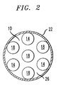
- FIG. 2 illustrates a view looking down a cross-section of beam line 10 taken along line 2-2 of FIG. 1.
- Conduit 22 includes a plurality of transmitting probes 14 and receiving probes 18 around its inner edge.
- the laser of hub 11 Fig. 1
- Second terminal unit 26 is illustrated herein as comprising a receiving probe 18.
- second terminal unit 26 may also include a transmitter 12, not shown.
- second terminal unit 26 may comprise another hub or an end cap.
- An end cap may be absorptive in order to stop the beam line 10 or may be reflective (i.e., a mirror or retroreflector) to recycle beam line 10 in the opposite direction.
- Transmitting probe assembly 14 includes transmit electro-optical components 12, and the receiving probe assembly 18 includes receive electro-optical components 16.
- Light of a pre-specified, closely controlled wavelength is transmitted over free space beam line 10 from transmit probe 14 to receive probe 18 to effect communication between two processing units in the system.
- Transmit electro-optical assembly 12 includes a laser 30 that operates at a controlled wavelength, a condensing lens 80, a fiber 82 to carry the light to the beam line and a diverging lens 36 and converging lens 38.
- Lenses 36 and 38 represent a reverse Galilean telescope that expands the small diverging beam from fiber 80 into a larger, less divergent beam, and directs it into free space beam line 10.
- Laser driver 40 energizes laser 30.
- Laser driver 40 includes circuits to provide the correct bias current and modulation to laser 30, but also includes elements necessary to control and monitor the emission wavelength of laser 30, as known in the art. Feedback is maintained between laser 30 and laser driver 40 to establish servo loops needed to precisely control the emission power, emission wavelength, and temperature of laser 30.
- Protocol handler 58 provides a serial bitstream used by laser driver 40 to modulate laser 30.
- Mux 60 merges data from all the various sources of bearer, control and administrative information arriving on links 310, which are to be transmitted to other processing units.
- Receive electro-optical assembly 16 includes a converging lens 306 to focus light from beam line 10 onto fiber 86.
- Fiber 86 carries the light from the beam line to wavelength selective photodetector 46.
- Lens 88 focus the light from fiber 86 to photodetector 46.
- Wavelength selective photodetector 46 includes a tunable optical bandpass filter, as known in the art, to select a single wavelength from the plurality of wavelengths present in beam line 10 (and on fiber 86). This filtering function must be very selective, as the wavelength spacing may be very close.
- the photoreceiver element, (i.e., a photodiode in the preferred embodiment) contained in 46 must be illuminated by only a single wavelength to reliably receive information from a single subchannel.
- Receiver circuit 48 includes all the circuits typical of known photoreceivers, including a transimpediance amplifier, clock recovery logic, and a decision circuit. In addition, receiver 48 includes elements needed to tune the wavelength selective filter contained in 46. Protocol handler 64 receives the serial stream and clock recovered in receiver circuit 48, and reassembles it into a data stream. This data stream (bearer, control and administrating data) is then sent to router/demux 66, which routes it to one of a plurality of possible destinations over links 68.
- FIG. 4 is a block diagram of hub 11, which may be first terminal unit 24 and/or second terminal unit 26 (FIG. 1). Hub 11 must simultaneously terminate all wavelengths on the free space beam line in each direction.
- Beam line 40 enters hub electro-optical assembly 400 through focusing lens 405.
- Light from beam line 40 passes through dichoric beam splitter 410, which divides the optical energy passing through into two bands: a band of longer wavelengths that pass straight through the beam splitter 410, and a shorter band of wavelengths that turn 90 degrees.
- Channels from the processing units are in the longer wavelength band, so they pass straight through the beam splitter 410, and are directed onto fiber 420. Wavelengths being sent to the processing units are in the shorter band, and therefore emerge from fiber 422, turned 90 degrees by beam splitter 410, and are transmitted through lens 405 and onto beam line 40.
- Erbium Doped Fiber Amplifier 424 boosts the amplitude of the receive optical signal, which passes through wavelength selective fiber splitter 428 and onto photoreceivers 432A - 432C, which contain photodiodes, transimpediance amplifiers, clock recovery circuits, and decision circuits, as known in the art.
- One photoreceiver is required per wavelength received at hub 11. Electrical signals from the photoreceivers then pass to router 435.
- Router 435 receives one electrical stream per wavelength from photoreceivers 432A - 432C, decodes their addresses, and routes them as electrical signals to the appropriate transmitter assembly 434A - 434C.
- Transmitter assemblies 434A - 434C include laser drivers, laser diodes, and feedback circuits to stabilize the laser's power and wavelength, as known in the art.
- Each of the optical transmitter assemblies 434A - 434C operates on a specific wavelength, with one transmitter required per wavelength transmitted into the beam line 40.
- Optical signals from transmitter assemblies 434A - 434C are combined in coupler 430, boosted by Erbium Doped Fiber Amplifier 426, and sent through beamsplitter 410 and lens 405 onto beam line 40.
- FIG. 5 represents a wavelength spectral plot of a WDM system according to an exemplary embodiment of this invention in operation. Eighty distinct wavelengths are used to interconnect 32 processing units in this exemplary embodiment. Each processing unit is assigned a single wavelength for transmission toward central hub 11, and a second wavelength over which hub 11 transmits messages back to the processing unit. Wavelengths used for transmission towards hub 11 are grouped in the longer wavelength spectrum, and wavelengths used to transmit from hub 11 back to the processing units occupy a group in the shorter wavelength spectrum.
- This plot represents output from a spectrophotometer monitoring the entire light spectrum in free space beam line 10.
- the horizontal axis 360 represents the wavelength of the monitored light, and the vertical axis 370 represents the power monitored on each wavelength.
- the group of 32 longer wavelength peaks 380 is the set of subchannel signals from the processing units toward the hub 11.
- the group of shorter wavelength peaks 382 is the optical signal set from the hub to the individual processing units.
- Unused wavelengths 384 and 386 are spare; to be used for system expansion or in case a failure requires reconfiguration of the wavelength assignments. Unused wavelengths 384 and 386 could also be used to balance the load of the system.
- Each processing unit transmits and receives its primary traffic on its assigned wavelengths 382 and 384, but if the traffic load exceeded the capacity of these channels, spare wavelengths 384 and 386 can be allocated to supplement the channels that are in overflow.
- spare wavelengths 384 and 386 can be allocated to supplement the channels that are in overflow.
- the supplemental wavelengths can be a shared, managed free resource pool.
- spare wavelengths 384 and 386 are activated, the amplitude of their peaks on FIG. 5 would increase.
- FIG. 6 is a flowchart for managing the dynamically allocated bandwidth available if more than one wavelength agile laser and photoreceiver is used at each processing unit.
- Dynamic bandwidth allocation operation starts at 450.
- decision diamond 452 a determination is made if any of the processing units have excessive bandwidth allocations. This determination is made by polling all processing units with more than one wavelength assigned in each direction, and calculating whether the total load has fallen below 90% of the capacity of a single channel. If so, the supplementary wavelength channel is de-allocated from the processing unit in action box 454. Any traffic that may be queued for transmission is allowed to clear in action box 456. Processing proceeds to action box 458, where the newly freed wavelength is added to the free list. In decision diamond 460, a determination is made if there are any remaining processing units to check for excess bandwidth.
- the determination of decision diamond 462 comprises determining if any subchannel is approaching overload. Each processing unit is polled to determine if its transmit queue is over 90% full. If so, decision diamond 564 determines if a supplementary wavelength is available to take the added traffic. If not, a system overload error is sent to the Operations Administration, Maintenance and Provisioning system in action box 466. If a supplementary wavelength is available, a wavelength is reserved in action box 468. The lasers and photoreceivers associated with both transmitters and both receivers are programmed to tune their wavelengths in action box 470. Tests are performed in action box 472 to determine if the new channels are performing correctly. In action box 474, the wavelength is allocated, and traffic begins to flow to relieve the overloaded primary wavelength. Decision diamond 478 tests to see if other processing units are in overload. The entire bandwidth management loop repeats infinitely as long as the system operates.
Landscapes
- Engineering & Computer Science (AREA)
- Computer Networks & Wireless Communication (AREA)
- Signal Processing (AREA)
- Physics & Mathematics (AREA)
- Electromagnetism (AREA)
- Computing Systems (AREA)
- Optical Communication System (AREA)
Abstract
Description
- This invention relates to the field of stored program controlled systems, including, but not limited to, telephone switching offices, data routers, and robotic machine tools; and, more specifically, this invention describes an optical communication path interconnect to provide communications for component processing units of the stored program controlled systems, wherein data is carried on the optical communication path using wavelength division multiplexing.
- A co-pending patent application discloses a system and method for interconnecting processing units of a stored program controlled system using free space optics. According to this disclosure, an optical beam line carries signals among the various processing units. Multiple distinct streams of data are communicated within that system. When multiple distinct communication streams within a system or network share the same physical media, a multiplexing and Media Access Control (MAC) protocol is necessary for optimal system operation. These protocols help insure that the system performs at the desired capacity, performance and reliability levels.
- One important function of any multiplexing and MAC protocol is to divide the limited capacity of the shared physical communication channel among the various logical streams or subchannels that share it. This subdivision of the shared physical channel provides capacity guarantees, so that each of the logical channels has an equal portion of the available capacity, or a pre-arranged larger or smaller proportion of this capacity. Pre-allocation of capacity provides a guaranteed level of capacity to all users. Such pre-allocation is often wasteful of system capacity because, if a given subchannel has no traffic to send, other sub-channels may have more traffic than they can handle.
- Other multiplexing and MAC protocols provide statistical multiplexing of the system's capacity, where in all potential transmitters on the shared channel negotiate for an opportunity to transmit. The theoretical maximum load offered, if all transmitters are operating at full rate, often exceeded the capacity of the shared media, which requires various buffering, queuing and priority techniques to govern when each transmitter operates. This system has potential channel utilization efficiency advantages, at the expense of making it more difficult to guarantee a minimum individual subchannel capacity.
- Another important function of any multiplexing and MAC protocol is to direct or route a given channel's traffic to the intended receiver over the shared medium. Channels in an optical system are often statically mapped using separate wavelengths (or similar separators as known in the art), and the receiver is determined by the wavelength assigned to the transmitter. In other cases, traffic is offered to the shared medium as packets. These packets contain a destination address, which is used by switching or routing functions to complete the connections.
- The concept of priority is also important to multiplexing and MAC protocols. Some messages have a higher priority than others, based upon the importance or time sensitivity of their contents. The multiplexing and MAC protocol must take priority into account as it manages access to the shared medium.
- Security is often an intrinsic function of multiplexing and MAC protocols. If there is a hazard associated with un-authorized listeners interception of a messages over the shared medium, the protocol can take steps to eliminate (or at least greatly reduce the impact of) this hazard. One means for heightened security is physically separating sensitive traffic from all other traffic in the various parallel sub-media in the transmission medium. A more common approach is to use some form of encryption at the transmitter, and decryption at only the authorized receiver(s).
- A further function that multiplexing and MAC protocols provide is fault tolerance and fault recovery. If a failure occurs that disables the shared media or significantly reduces its capacity, the protocol invokes various diagnostic actions to discover the source of the problem and then appropriate recovery actions to attempt to correct the source of the problem. Often, the fault recovery operation involves switching the traffic to a redundant medium or attempting to shed load so only the highest priority traffic is allowed on the remaining capacity.
- One form of multiplexing and MAC protocols usable in a free space optical beam line medium is wavelength division multiplexing. In a Wavelength Division Multiplexed (WDM) system, the shared medium is divided into a set of simultaneously-transmitted wavelengths. All subchannels sharing the medium are assigned specific wavelengths on which to carry traffic. The number of different wavelengths assigned may be equal for all subchannels, or some subchannels may be given higher capacity by assigning them a higher proportion of wavelengths available on the beam line on which to transmit.
- Therefore, there is a need in the art to provide a free space optical interconnect between units of a stored program controlled system using a wavelength division multiplex system.
- This need is satisfied and a technical advance is achieved in the art by a system and method that provides wavelength division multiplexing in a system that uses free space optics to interconnect processing units of a stored program controlled system. The system of this invention uses Wavelength Division Multiplexing (WDM) techniques to provide a plurality of logically independent subchannels over a single shared free space optical beam line. The single logical beam is divided among the subchannels, with each subchannel operating on a selected wavelength or wavelengths.
- In static WDM mapping, wavelengths are assigned to subchannels when the system is configured, and each processing unit using the beam line has a predetermined wavelength or wavelengths for communication with other processing units. The wavelength assignment may also be determined as the processing units are installed by selecting a laser of an individually designated wavelength at each transmit probe and a wavelength selective filter optical element at each receive probe. An alternate embodiment, dynamic mapping, uses frequency agile lasers and tunable filters at the receive probes to dynamically assign wavelengths to the various subchannels. Dynamic assignment has advantages in versatility, and reliability, but at the cost of more complex hardware.
- A more complete understanding of this invention may be obtained from a consideration of the specification taken in conjunction with the drawings, in which:
- FIG. 1 is a perspective view of a beam line illustrating the relationship of the beam line and probes according to a general overview of an exemplary embodiment of this invention;
- FIG. 2 is a cross-sectional view of the beam line taken along line 2-2 of FIG. 1;
- FIG. 3 is an exemplary embodiment of transmitting and receiving probes of FIGs. 1 and 2;
- FIG. 4 is a block diagram of a hub of the beam line of FIG.'s 1 and 2 according to an exemplary embodiment of this invention;
- FIG. 5 is a representative wavelength spectrum of the beam line of FIG. 1 operating at full capacity; and
- FIG. 6 is a flowchart of processing for bandwidth management tasks of increasing and decreasing the capacity of each subchannel.
-
- Turning to FIG. 1, a perspective view of a free
space beam line 10 according to an exemplary embodiment of this invention is shown. According to this exemplary embodiment, a freespace beam line 10 is generated at hub 11 which projects optically encoded signals, as will be described below in connection with FIG. 4 - A plurality of
transmitters 12 within transmittingprobes 14 andreceivers 16 within receivingprobes 18 are distributed throughoutbeam line 10 along the outer periphery in the form of a spiral or helix, in this exemplary embodiment. Other possible configurations of probes along the beam line will be apparent to one skilled in the art after studying this disclosure. The probes are distributed in a helix in this exemplary embodiment so that there is a minimal amount of shadowing; that is, one probe being in the shadow of a previous probe inbeam line 10, inhibiting the probe in the shadow from transmitting or to receiving signals inbeam line 10. -
Beam line 10 may be contained within a reserved volume orconduit 22 in an enclosure, such as a cylinder or pipe or, alternatively, may be in the open. If thebeam line 10 is contained in a conduit, then the interior surface may be optically absorptive or optically reflective depending upon the length of the pipe, the wavelength of the signal generated by the laser withintransmitter 12 and loss budget to provide optimal reception of optically encoded signal by the plurality of receivingprobes 18 throughout the length ofbeam line 10. -
Conduit 22 includes, in this exemplary embodiment, afirst terminal unit 24 comprising a hub 11 and asecond terminal unit 26.First terminal unit 24 originates freespace beam line 10 andsecond terminal unit 26 terminates the portion of freespace beam line 10 passing beyond theprobes 18. As will be discussed further, below,first terminal unit 24 and/orsecond terminal unit 26 may include both transmitters and receivers, and may be also interconnected to recycle the encoded signal. - FIG. 2 illustrates a view looking down a cross-section of
beam line 10 taken along line 2-2 of FIG. 1.Conduit 22 includes a plurality of transmittingprobes 14 and receivingprobes 18 around its inner edge. In the illustration of FIG. 2, the laser of hub 11 (Fig. 1) focusesbeam line 10 to encompass the interior circumference ofconduit 22 whereby eachprobe 18 receives the encoded optical signal.Second terminal unit 26 is illustrated herein as comprising areceiving probe 18. (Secondterminal unit 26 may also include atransmitter 12, not shown.) Alternatively, secondterminal unit 26 may comprise another hub or an end cap. An end cap may be absorptive in order to stop thebeam line 10 or may be reflective (i.e., a mirror or retroreflector) to recyclebeam line 10 in the opposite direction. - Turning now to FIG. 3, exemplary embodiments of a transmitting
probe 14 and a receivingprobe 18 configured for wavelength division multiplexing (WDM) of the bandwidth of a beam line are shown. Transmittingprobe assembly 14 includes transmit electro-optical components 12, and the receivingprobe assembly 18 includes receive electro-optical components 16. Light of a pre-specified, closely controlled wavelength is transmitted over freespace beam line 10 from transmitprobe 14 to receiveprobe 18 to effect communication between two processing units in the system. - Transmit electro-
optical assembly 12 includes alaser 30 that operates at a controlled wavelength, a condensing lens 80, afiber 82 to carry the light to the beam line and a diverginglens 36 and converginglens 38.Lenses space beam line 10. -
Laser driver 40 energizeslaser 30.Laser driver 40 includes circuits to provide the correct bias current and modulation tolaser 30, but also includes elements necessary to control and monitor the emission wavelength oflaser 30, as known in the art. Feedback is maintained betweenlaser 30 andlaser driver 40 to establish servo loops needed to precisely control the emission power, emission wavelength, and temperature oflaser 30.Protocol handler 58 provides a serial bitstream used bylaser driver 40 to modulatelaser 30.Mux 60 merges data from all the various sources of bearer, control and administrative information arriving onlinks 310, which are to be transmitted to other processing units. - Receive electro-
optical assembly 16 includes a converginglens 306 to focus light frombeam line 10 ontofiber 86.Fiber 86 carries the light from the beam line to wavelengthselective photodetector 46.Lens 88 focus the light fromfiber 86 tophotodetector 46. - Wavelength
selective photodetector 46 includes a tunable optical bandpass filter, as known in the art, to select a single wavelength from the plurality of wavelengths present in beam line 10 (and on fiber 86). This filtering function must be very selective, as the wavelength spacing may be very close. The photoreceiver element, (i.e., a photodiode in the preferred embodiment) contained in 46 must be illuminated by only a single wavelength to reliably receive information from a single subchannel. -
Receiver circuit 48 includes all the circuits typical of known photoreceivers, including a transimpediance amplifier, clock recovery logic, and a decision circuit. In addition,receiver 48 includes elements needed to tune the wavelength selective filter contained in 46.Protocol handler 64 receives the serial stream and clock recovered inreceiver circuit 48, and reassembles it into a data stream. This data stream (bearer, control and administrating data) is then sent to router/demux 66, which routes it to one of a plurality of possible destinations overlinks 68. - FIG. 4 is a block diagram of hub 11, which may be first
terminal unit 24 and/or second terminal unit 26 (FIG. 1). Hub 11 must simultaneously terminate all wavelengths on the free space beam line in each direction.Beam line 40 enters hub electro-optical assembly 400 through focusinglens 405. Light frombeam line 40 passes throughdichoric beam splitter 410, which divides the optical energy passing through into two bands: a band of longer wavelengths that pass straight through thebeam splitter 410, and a shorter band of wavelengths that turn 90 degrees. Channels from the processing units are in the longer wavelength band, so they pass straight through thebeam splitter 410, and are directed ontofiber 420. Wavelengths being sent to the processing units are in the shorter band, and therefore emerge fromfiber 422, turned 90 degrees bybeam splitter 410, and are transmitted throughlens 405 and ontobeam line 40. - Erbium
Doped Fiber Amplifier 424 boosts the amplitude of the receive optical signal, which passes through wavelengthselective fiber splitter 428 and ontophotoreceivers 432A - 432C, which contain photodiodes, transimpediance amplifiers, clock recovery circuits, and decision circuits, as known in the art. One photoreceiver is required per wavelength received at hub 11. Electrical signals from the photoreceivers then pass torouter 435.Router 435 receives one electrical stream per wavelength fromphotoreceivers 432A - 432C, decodes their addresses, and routes them as electrical signals to theappropriate transmitter assembly 434A - 434C. -
Transmitter assemblies 434A - 434C include laser drivers, laser diodes, and feedback circuits to stabilize the laser's power and wavelength, as known in the art. Each of theoptical transmitter assemblies 434A - 434C operates on a specific wavelength, with one transmitter required per wavelength transmitted into thebeam line 40. Optical signals fromtransmitter assemblies 434A - 434C are combined incoupler 430, boosted by ErbiumDoped Fiber Amplifier 426, and sent throughbeamsplitter 410 andlens 405 ontobeam line 40. - FIG. 5 represents a wavelength spectral plot of a WDM system according to an exemplary embodiment of this invention in operation. Eighty distinct wavelengths are used to interconnect 32 processing units in this exemplary embodiment. Each processing unit is assigned a single wavelength for transmission toward central hub 11, and a second wavelength over which hub 11 transmits messages back to the processing unit. Wavelengths used for transmission towards hub 11 are grouped in the longer wavelength spectrum, and wavelengths used to transmit from hub 11 back to the processing units occupy a group in the shorter wavelength spectrum.
- This plot represents output from a spectrophotometer monitoring the entire light spectrum in free
space beam line 10. Thehorizontal axis 360 represents the wavelength of the monitored light, and thevertical axis 370 represents the power monitored on each wavelength. The group of 32 longer wavelength peaks 380 is the set of subchannel signals from the processing units toward the hub 11. The group of shorter wavelength peaks 382 is the optical signal set from the hub to the individual processing units.Unused wavelengths Unused wavelengths wavelengths spare wavelengths spare wavelengths - FIG. 6 is a flowchart for managing the dynamically allocated bandwidth available if more than one wavelength agile laser and photoreceiver is used at each processing unit. Dynamic bandwidth allocation operation starts at 450. In
decision diamond 452, a determination is made if any of the processing units have excessive bandwidth allocations. This determination is made by polling all processing units with more than one wavelength assigned in each direction, and calculating whether the total load has fallen below 90% of the capacity of a single channel. If so, the supplementary wavelength channel is de-allocated from the processing unit inaction box 454. Any traffic that may be queued for transmission is allowed to clear inaction box 456. Processing proceeds toaction box 458, where the newly freed wavelength is added to the free list. Indecision diamond 460, a determination is made if there are any remaining processing units to check for excess bandwidth. - The determination of
decision diamond 462 comprises determining if any subchannel is approaching overload. Each processing unit is polled to determine if its transmit queue is over 90% full. If so, decision diamond 564 determines if a supplementary wavelength is available to take the added traffic. If not, a system overload error is sent to the Operations Administration, Maintenance and Provisioning system inaction box 466. If a supplementary wavelength is available, a wavelength is reserved inaction box 468. The lasers and photoreceivers associated with both transmitters and both receivers are programmed to tune their wavelengths inaction box 470. Tests are performed inaction box 472 to determine if the new channels are performing correctly. Inaction box 474, the wavelength is allocated, and traffic begins to flow to relieve the overloaded primary wavelength. Decision diamond 478 tests to see if other processing units are in overload. The entire bandwidth management loop repeats infinitely as long as the system operates.
Claims (14)
- A method for use in a stored program controlled system comprising a plurality of processing units and a signal generator for interconnecting processing units using wavelength division multiplexing over a free space beam line, said method including the steps of:generating a message at one of said plurality of processing units for a destination processing unit comprising another one of said plurality of processing units;modulating the message on a specific optical wavelength;transmitting the modulated message over said free space beam line;receiving said modulated message at a wavelength selective receiver;selecting a particular wavelength at said receiver; andrecreating the message and forwarding it to said destination processing unit.
- A method in accordance with claim 1 wherein said signal generator includes a tunable laser, said step of modulating comprising:tuning said tunable laser to said specific optical wavelength prior to modulating the message on said specific optical wavelength.
- A method in accordance with claim 1 wherein said signal generator includes a plurality of fixed wavelength lasers, each of which operates on a different wavelength, said step of modulating comprising:delivering said message to one of said plurality of fixed wavelength lasers corresponding to said specific optical wavelength prior to modulating the message on said specific optical wavelength.
- A method in accordance with claim 1 wherein said wavelength selective receiver comprises tunable photodetectors, said step of selecting comprising:tuning said tunable photodetector to said specific optical wavelength.
- A method in accordance with claim 1 wherein said wavelength selective receiver comprises one of a plurality of fixed wavelength photodetectors, all operating at different wavelengths, said step of selecting comprising:receiving only the fixed wavelength.
- A method in accordance with claim 1 wherein said wavelength selective receiver comprises one of a plurality of fixed wavelength photodetectors and a tunable photodetector, said method further including the step of:dynamically allocating bandwidth by receiving messages on a primary wavelength at said one of a plurality of fixed wavelength photodetectors and receiving one or more messages on other wavelengths at said tunable photodetector.
- A method in accordance with claim 1 wherein each of said processing units includes a fixed transmitter comprising a laser configured to modulate on a fixed optical wavelength over said free space optical beam line and a tunable transmitter comprising a tunable laser configured to modulate on multiple, selectable wavelengths, said method further including the step of:dynamically allocating bandwidth by transmitting messages on a primary wavelength at said fixed wavelength transmitter and transmitting one or more messages on other wavelengths at said tunable transmitter.
- A system for use in a stored program controlled system comprising a plurality of processing units for interconnecting said processing units using wavelength division multiplexing over a free space optical beam line, said system comprising:a transmitter configured to generate a message at one of said plurality of processing units for a destination processing unit comprising another one of said plurality of processing units;a laser configured to modulate the message on a specific optical wavelength over said free space optical beam line;a wavelength selective receiver; andmeans at said receiver for recreating the message and forwarding it to said destination processing unit.
- A system in accordance with claim 8 wherein said laser comprises a tunable laser configured to modulate at a specific optical wavelength before transmitting said message.
- A system in accordance with claim 8 wherein said laser comprises a fixed wavelength laser.
- A system in accordance with claim 8 wherein said wavelength selective receiver comprises a tunable photodetector.
- A system in accordance with claim 8 wherein said wavelength selective receiver comprises a fixed wavelength photodetector.
- A system in accordance with claim 8 wherein said wavelength selective receiver comprises a fixed wavelength photodetector and a tunable photodetector configured to dynamically allocating bandwidth by receiving messages on a primary wavelength at said one of a plurality of fixed wavelength photodetectors and receiving one or more messages on other wavelengths at said tunable photodetector.
- A system in accordance with claim 8 further including means for dynamic wavelength allocation and deallocation responsive to system load.
Applications Claiming Priority (2)
| Application Number | Priority Date | Filing Date | Title |
|---|---|---|---|
| US932705 | 2001-08-17 | ||
| US09/932,705 US20030035169A1 (en) | 2001-08-17 | 2001-08-17 | Interconnecting processing units of a stored program controlled system using wavelength division muliplexed free space optics |
Publications (2)
| Publication Number | Publication Date |
|---|---|
| EP1284430A1 true EP1284430A1 (en) | 2003-02-19 |
| EP1284430B1 EP1284430B1 (en) | 2006-04-26 |
Family
ID=25462761
Family Applications (1)
| Application Number | Title | Priority Date | Filing Date |
|---|---|---|---|
| EP02254780A Expired - Lifetime EP1284430B1 (en) | 2001-08-17 | 2002-07-09 | Method and apparatus for interconnecting processors by WDM |
Country Status (3)
| Country | Link |
|---|---|
| US (1) | US20030035169A1 (en) |
| EP (1) | EP1284430B1 (en) |
| DE (1) | DE60210875T2 (en) |
Families Citing this family (6)
| Publication number | Priority date | Publication date | Assignee | Title |
|---|---|---|---|---|
| FR2832883B1 (en) * | 2001-11-27 | 2006-05-26 | Cit Alcatel | DIGITAL SIGNAL TRANSMISSION SYSTEM FOR A SPA VEHICLE |
| US7587141B2 (en) | 2005-08-02 | 2009-09-08 | Itt Manufacturing Enterprises, Inc. | Communication transceiver architecture |
| US8605580B2 (en) * | 2006-07-05 | 2013-12-10 | The Board Of Regents Of The University Of Oklahoma | Maximization of throughput under a fairness constraint in DWDM-based optical networks |
| US8346087B2 (en) * | 2007-09-28 | 2013-01-01 | Oracle America, Inc. | Wavelength-division multiplexing for use in multi-chip systems |
| EP2666097B1 (en) * | 2011-01-20 | 2017-10-25 | Hewlett-Packard Enterprise Development LP | Composite processors |
| DE102017209094A1 (en) * | 2017-05-31 | 2018-12-06 | Osram Gmbh | WIRELESS TRANSMISSION OF DATA BETWEEN A COMMUNICATION TERMINAL POSITIONED IN A PRESENT AREA AND A COMMUNICATION OBJECT |
Citations (3)
| Publication number | Priority date | Publication date | Assignee | Title |
|---|---|---|---|---|
| EP0811862A2 (en) * | 1996-06-03 | 1997-12-10 | Nippon Telegraph And Telephone Corporation | Board-to-board and unit-to-unit optical interconnection system |
| EP0876019A2 (en) * | 1997-04-30 | 1998-11-04 | AT&T Corp. | Optical receiver and demultiplexer for free-space wavelength division multiplexing communications system |
| GB2334396A (en) * | 1998-04-02 | 1999-08-18 | Bookham Technology Ltd | Connecting circuit boards using optical WDM signals |
Family Cites Families (2)
| Publication number | Priority date | Publication date | Assignee | Title |
|---|---|---|---|---|
| WO1996011539A2 (en) * | 1994-10-04 | 1996-04-18 | Sdl, Inc. | Infrared laser diode wireless local area network |
| US6735393B1 (en) * | 1999-09-24 | 2004-05-11 | Telenor, As | All-optical network with passive wavelength routers |
-
2001
- 2001-08-17 US US09/932,705 patent/US20030035169A1/en not_active Abandoned
-
2002
- 2002-07-09 DE DE60210875T patent/DE60210875T2/en not_active Expired - Lifetime
- 2002-07-09 EP EP02254780A patent/EP1284430B1/en not_active Expired - Lifetime
Patent Citations (3)
| Publication number | Priority date | Publication date | Assignee | Title |
|---|---|---|---|---|
| EP0811862A2 (en) * | 1996-06-03 | 1997-12-10 | Nippon Telegraph And Telephone Corporation | Board-to-board and unit-to-unit optical interconnection system |
| EP0876019A2 (en) * | 1997-04-30 | 1998-11-04 | AT&T Corp. | Optical receiver and demultiplexer for free-space wavelength division multiplexing communications system |
| GB2334396A (en) * | 1998-04-02 | 1999-08-18 | Bookham Technology Ltd | Connecting circuit boards using optical WDM signals |
Also Published As
| Publication number | Publication date |
|---|---|
| US20030035169A1 (en) | 2003-02-20 |
| DE60210875D1 (en) | 2006-06-01 |
| DE60210875T2 (en) | 2007-05-24 |
| EP1284430B1 (en) | 2006-04-26 |
Similar Documents
| Publication | Publication Date | Title |
|---|---|---|
| US11637633B2 (en) | Optical transmission apparatus, optical reception apparatus, optical communications apparatus, optical communication system, and methods of controlling them | |
| US9634791B2 (en) | Flexible optical spectrum management systems and methods | |
| US7092642B2 (en) | Tunable channel spacing for wavelength division multiplexing (WDM) transport system | |
| JP6271757B2 (en) | Optical network on chip, and method and apparatus for dynamically adjusting optical link bandwidth | |
| US8041217B2 (en) | System and method for managing wavelength drift in an optical network | |
| JP7599080B2 (en) | Optical transmitting device, optical receiving device, optical communication device, optical communication system, and control method thereof | |
| US20170134114A1 (en) | Flexible grid optical spectrum transmitter, receiver, and transceiver | |
| US7609966B2 (en) | Method and system for time-sharing transmission frequencies in an optical network | |
| JP2005244973A (en) | Optical network with selective mode switching | |
| EP2774301A1 (en) | Wson restoration | |
| WO2011005223A1 (en) | Method and system for wavelength allocation in a wdm/tdm passive optical network | |
| US20020018260A1 (en) | Multimedia optical community area network | |
| CN101536537B (en) | Method of managing connections in an optical access network and related platforms, exchanges, networks and computer software products | |
| EP1284430B1 (en) | Method and apparatus for interconnecting processors by WDM | |
| US8676956B1 (en) | Method and system for monitoring network resources utilization | |
| CN112913164B (en) | Time and wave division multiplexing | |
| CA2272786C (en) | Low-latency high-bandwidth tdm-wdm network architecture | |
| US7386233B2 (en) | Ring network made using a dual optical data bus | |
| US9270376B2 (en) | Method of allocating bandwidth in an optical network | |
| JP2006074765A (en) | Method and system for data centric architecture in optical networks | |
| JP3595332B2 (en) | Communications system | |
| JP4016953B2 (en) | Optical transmission system | |
| JP3595331B2 (en) | Communications system | |
| KR100617307B1 (en) | Connection configuration method and connection reconfiguration method in optical network | |
| US20020075547A1 (en) | High-speed optical data network with improved optical receiver |
Legal Events
| Date | Code | Title | Description |
|---|---|---|---|
| PUAI | Public reference made under article 153(3) epc to a published international application that has entered the european phase |
Free format text: ORIGINAL CODE: 0009012 |
|
| 17P | Request for examination filed |
Effective date: 20020720 |
|
| AK | Designated contracting states |
Designated state(s): AT BE BG CH CY CZ DE DK EE ES FI FR GB GR IE IT LI LU MC NL PT SE SK TR |
|
| AX | Request for extension of the european patent |
Extension state: AL LT LV MK RO SI |
|
| 17Q | First examination report despatched |
Effective date: 20030623 |
|
| AKX | Designation fees paid |
Designated state(s): DE FR GB |
|
| GRAP | Despatch of communication of intention to grant a patent |
Free format text: ORIGINAL CODE: EPIDOSNIGR1 |
|
| GRAS | Grant fee paid |
Free format text: ORIGINAL CODE: EPIDOSNIGR3 |
|
| GRAA | (expected) grant |
Free format text: ORIGINAL CODE: 0009210 |
|
| AK | Designated contracting states |
Kind code of ref document: B1 Designated state(s): DE FR GB |
|
| REG | Reference to a national code |
Ref country code: GB Ref legal event code: FG4D |
|
| REF | Corresponds to: |
Ref document number: 60210875 Country of ref document: DE Date of ref document: 20060601 Kind code of ref document: P |
|
| ET | Fr: translation filed | ||
| PLBE | No opposition filed within time limit |
Free format text: ORIGINAL CODE: 0009261 |
|
| STAA | Information on the status of an ep patent application or granted ep patent |
Free format text: STATUS: NO OPPOSITION FILED WITHIN TIME LIMIT |
|
| 26N | No opposition filed |
Effective date: 20070129 |
|
| REG | Reference to a national code |
Ref country code: GB Ref legal event code: 732E Free format text: REGISTERED BETWEEN 20131107 AND 20131113 |
|
| REG | Reference to a national code |
Ref country code: FR Ref legal event code: CD Owner name: ALCATEL-LUCENT USA INC. Effective date: 20131122 |
|
| REG | Reference to a national code |
Ref country code: FR Ref legal event code: GC Effective date: 20140410 |
|
| REG | Reference to a national code |
Ref country code: FR Ref legal event code: RG Effective date: 20141015 |
|
| REG | Reference to a national code |
Ref country code: FR Ref legal event code: PLFP Year of fee payment: 14 |
|
| REG | Reference to a national code |
Ref country code: FR Ref legal event code: PLFP Year of fee payment: 15 |
|
| PGFP | Annual fee paid to national office [announced via postgrant information from national office to epo] |
Ref country code: DE Payment date: 20160722 Year of fee payment: 15 Ref country code: GB Payment date: 20160721 Year of fee payment: 15 |
|
| PGFP | Annual fee paid to national office [announced via postgrant information from national office to epo] |
Ref country code: FR Payment date: 20160721 Year of fee payment: 15 |
|
| REG | Reference to a national code |
Ref country code: DE Ref legal event code: R119 Ref document number: 60210875 Country of ref document: DE |
|
| GBPC | Gb: european patent ceased through non-payment of renewal fee |
Effective date: 20170709 |
|
| REG | Reference to a national code |
Ref country code: FR Ref legal event code: ST Effective date: 20180330 |
|
| PG25 | Lapsed in a contracting state [announced via postgrant information from national office to epo] |
Ref country code: DE Free format text: LAPSE BECAUSE OF NON-PAYMENT OF DUE FEES Effective date: 20180201 Ref country code: GB Free format text: LAPSE BECAUSE OF NON-PAYMENT OF DUE FEES Effective date: 20170709 |
|
| PG25 | Lapsed in a contracting state [announced via postgrant information from national office to epo] |
Ref country code: FR Free format text: LAPSE BECAUSE OF NON-PAYMENT OF DUE FEES Effective date: 20170731 |
|
| REG | Reference to a national code |
Ref country code: DE Ref legal event code: R081 Ref document number: 60210875 Country of ref document: DE Owner name: WSOU INVESTMENTS, LLC, LOS ANGELES, US Free format text: FORMER OWNER: LUCENT TECHNOLOGIES INC., MURRAY HILL, N.J., US |