EP1284373A1 - Tunable slip yoke damper assembly - Google Patents
Tunable slip yoke damper assembly Download PDFInfo
- Publication number
- EP1284373A1 EP1284373A1 EP02255099A EP02255099A EP1284373A1 EP 1284373 A1 EP1284373 A1 EP 1284373A1 EP 02255099 A EP02255099 A EP 02255099A EP 02255099 A EP02255099 A EP 02255099A EP 1284373 A1 EP1284373 A1 EP 1284373A1
- Authority
- EP
- European Patent Office
- Prior art keywords
- inner housing
- magnetic means
- assembly
- damper assembly
- assembly according
- Prior art date
- Legal status (The legal status is an assumption and is not a legal conclusion. Google has not performed a legal analysis and makes no representation as to the accuracy of the status listed.)
- Withdrawn
Links
- 230000005291 magnetic effect Effects 0.000 claims abstract description 40
- 229920001971 elastomer Polymers 0.000 claims abstract description 34
- 239000000806 elastomer Substances 0.000 claims abstract description 33
- 238000000034 method Methods 0.000 claims description 5
- 230000007423 decrease Effects 0.000 claims description 3
- 238000013016 damping Methods 0.000 claims description 2
- 239000002184 metal Substances 0.000 claims 4
- 230000003247 decreasing effect Effects 0.000 abstract 1
- 238000012360 testing method Methods 0.000 description 3
- 230000005294 ferromagnetic effect Effects 0.000 description 2
- 239000000463 material Substances 0.000 description 2
- 229910001018 Cast iron Inorganic materials 0.000 description 1
- 244000043261 Hevea brasiliensis Species 0.000 description 1
- 238000011161 development Methods 0.000 description 1
- 238000012986 modification Methods 0.000 description 1
- 230000004048 modification Effects 0.000 description 1
- 229920003052 natural elastomer Polymers 0.000 description 1
- 229920001194 natural rubber Polymers 0.000 description 1
- 230000005298 paramagnetic effect Effects 0.000 description 1
- 239000002245 particle Substances 0.000 description 1
- 239000011236 particulate material Substances 0.000 description 1
- 238000003466 welding Methods 0.000 description 1
Images
Classifications
-
- F—MECHANICAL ENGINEERING; LIGHTING; HEATING; WEAPONS; BLASTING
- F16—ENGINEERING ELEMENTS AND UNITS; GENERAL MEASURES FOR PRODUCING AND MAINTAINING EFFECTIVE FUNCTIONING OF MACHINES OR INSTALLATIONS; THERMAL INSULATION IN GENERAL
- F16F—SPRINGS; SHOCK-ABSORBERS; MEANS FOR DAMPING VIBRATION
- F16F15/00—Suppression of vibrations in systems; Means or arrangements for avoiding or reducing out-of-balance forces, e.g. due to motion
- F16F15/10—Suppression of vibrations in rotating systems by making use of members moving with the system
- F16F15/14—Suppression of vibrations in rotating systems by making use of members moving with the system using masses freely rotating with the system, i.e. uninvolved in transmitting driveline torque, e.g. rotative dynamic dampers
- F16F15/1407—Suppression of vibrations in rotating systems by making use of members moving with the system using masses freely rotating with the system, i.e. uninvolved in transmitting driveline torque, e.g. rotative dynamic dampers the rotation being limited with respect to the driving means
- F16F15/1414—Masses driven by elastic elements
- F16F15/1435—Elastomeric springs, i.e. made of plastic or rubber
- F16F15/1442—Elastomeric springs, i.e. made of plastic or rubber with a single mass
-
- F—MECHANICAL ENGINEERING; LIGHTING; HEATING; WEAPONS; BLASTING
- F16—ENGINEERING ELEMENTS AND UNITS; GENERAL MEASURES FOR PRODUCING AND MAINTAINING EFFECTIVE FUNCTIONING OF MACHINES OR INSTALLATIONS; THERMAL INSULATION IN GENERAL
- F16D—COUPLINGS FOR TRANSMITTING ROTATION; CLUTCHES; BRAKES
- F16D3/00—Yielding couplings, i.e. with means permitting movement between the connected parts during the drive
- F16D3/16—Universal joints in which flexibility is produced by means of pivots or sliding or rolling connecting parts
- F16D3/26—Hooke's joints or other joints with an equivalent intermediate member to which each coupling part is pivotally or slidably connected
- F16D3/38—Hooke's joints or other joints with an equivalent intermediate member to which each coupling part is pivotally or slidably connected with a single intermediate member with trunnions or bearings arranged on two axes perpendicular to one another
-
- F—MECHANICAL ENGINEERING; LIGHTING; HEATING; WEAPONS; BLASTING
- F16—ENGINEERING ELEMENTS AND UNITS; GENERAL MEASURES FOR PRODUCING AND MAINTAINING EFFECTIVE FUNCTIONING OF MACHINES OR INSTALLATIONS; THERMAL INSULATION IN GENERAL
- F16F—SPRINGS; SHOCK-ABSORBERS; MEANS FOR DAMPING VIBRATION
- F16F1/00—Springs
- F16F1/36—Springs made of rubber or other material having high internal friction, e.g. thermoplastic elastomers
- F16F1/3605—Springs made of rubber or other material having high internal friction, e.g. thermoplastic elastomers characterised by their material
- F16F1/361—Springs made of rubber or other material having high internal friction, e.g. thermoplastic elastomers characterised by their material comprising magneto-rheological elastomers [MR]
-
- F—MECHANICAL ENGINEERING; LIGHTING; HEATING; WEAPONS; BLASTING
- F16—ENGINEERING ELEMENTS AND UNITS; GENERAL MEASURES FOR PRODUCING AND MAINTAINING EFFECTIVE FUNCTIONING OF MACHINES OR INSTALLATIONS; THERMAL INSULATION IN GENERAL
- F16F—SPRINGS; SHOCK-ABSORBERS; MEANS FOR DAMPING VIBRATION
- F16F2224/00—Materials; Material properties
- F16F2224/02—Materials; Material properties solids
- F16F2224/025—Elastomers
-
- F—MECHANICAL ENGINEERING; LIGHTING; HEATING; WEAPONS; BLASTING
- F16—ENGINEERING ELEMENTS AND UNITS; GENERAL MEASURES FOR PRODUCING AND MAINTAINING EFFECTIVE FUNCTIONING OF MACHINES OR INSTALLATIONS; THERMAL INSULATION IN GENERAL
- F16F—SPRINGS; SHOCK-ABSORBERS; MEANS FOR DAMPING VIBRATION
- F16F2224/00—Materials; Material properties
- F16F2224/04—Fluids
- F16F2224/045—Fluids magnetorheological
-
- F—MECHANICAL ENGINEERING; LIGHTING; HEATING; WEAPONS; BLASTING
- F16—ENGINEERING ELEMENTS AND UNITS; GENERAL MEASURES FOR PRODUCING AND MAINTAINING EFFECTIVE FUNCTIONING OF MACHINES OR INSTALLATIONS; THERMAL INSULATION IN GENERAL
- F16F—SPRINGS; SHOCK-ABSORBERS; MEANS FOR DAMPING VIBRATION
- F16F2228/00—Functional characteristics, e.g. variability, frequency-dependence
- F16F2228/06—Stiffness
- F16F2228/066—Variable stiffness
Definitions
- This invention generally relates to a driveline assembly in a motor vehicle and more particularly to a damper assembly installed in a slip yoke of a driveline assembly of a motor vehicle.
- the Slip Yoke Damper As part of the often used arsenal of NVH devices used to combat gear noise issues in the driveline system, the Slip Yoke Damper (SYD) has proved to be an integral component within many of the driveline systems currently in use.
- SYD Slip Yoke Damper
- One of the core problems in the use of an SYD during the development phase is the lead time necessary to order and receive a correctly tuned damper.
- MR elastomers present the possibility of a tunable device due to the change in material characteristics with the introduction of a magnetic field.
- the SYD assembly will make use of the variable adjustment of magnetically charged bolts, which changes the modulus of the material, and thus, the tuned frequency of the SYD.
- the ability to tune the SYD to a different frequency will reduce the lead time necessary to test the slip yoke dampers.
- a driveline assembly installed in a motor vehicle is generally illustrated by reference numeral 10.
- the driveline assembly 10 is adapted to transmit rotational power from an engine system 14 to a plurality of drive wheels (not shown).
- the driveline assembly 10 comprises a driveshaft 12 that transfers the rotational power through the driveline assembly 10.
- the driveshaft 12 is conventional in the art and preferably is an internally splined driveshaft 12.
- the driveline assembly 10 In order to connect the driveshaft 12 from the engine 14 to the wheels, the driveline assembly 10 typically includes at least one slip yoke assembly 16. Due to the rotational and axial movement of the driveshaft 12, driveline assembly 10 exhibits noise and vibrations. In order to reduce the noise and dampen the vibrations of the driveline assembly 10, a damper assembly 22 is incorporated in the driveline assembly 10. In the present invention, the damper assembly 22 is a part of the slip yoke assembly 16. The damper assembly 22 functions to dampen the vibration of the driveline assembly 10, such that the vibrations are not substantially transferred to the vehicular parts of the motor vehicle. In addition, the damper assembly 22 is also capable of being adjusted such that the modulus of the driveline assembly 10 can be altered to minimize the vibrations in the vehicle.
- the driveshaft 12 is connected to a slip yoke assembly 16, preferably the driveshaft 12 is welded to the slip yoke assembly 16.
- a slip yoke assembly 16 is conventional in the art and includes a yoke 18 and a universal cross joint 20.
- the yoke 18 is typically connected to a tubular end 17 that is attached to an engine shaft (not shown).
- a damper assembly 22 is installed in the slip yoke assembly 16.
- the damper assembly 22 of the present invention comprises a damper ring 24 that is fastened to the slip yoke assembly 16.
- the damper ring 24 is annular and is provided with a central opening 26.
- a plurality of holes 40 and 42 are provided in the universal cross joint 20.
- a corresponding set of openings 39 and 41 are provided in the damper ring 24.
- the damper ring 24 is fastened to the slip yoke assembly 16 by means of bolts 36 and 38.
- the bolts 36 and 38 are dimensioned such that they are adaptable to pass through the openings 39 and 41 in the damper ring 24 and fasten the damper ring 24 to the slip yoke assembly 16.
- other means such as welding may be used to fasten the damper ring 24 to the slip yoke assembly 16.
- the damper ring 24 is made of cast iron such that the damper ring 24 add more mass to the damper assembly 22 and functions to more effectively dampen the vibrations of the driveline assembly 10.
- the damper ring 24 preferably comprises an outer housing 30 and an inner housing 32.
- a gap 34 is defined between the outer housing 30 and the inner housing 32.
- the gap 34 between the outer housing 30 and the inner housing 32 is filled with magnetorheological (MR) elastomer 50.
- the MR elastomer therefore holds the outer housing 30 and the inner housing 32.
- the MR elastomer is conventional in the art and may comprise a suitable gel as an elastomer of natural rubber. The gel or elastomer has particulate materials embedded therein.
- Preferred particulates are those that are magnetisable by means of an applied magnetic field, that is, particulates having paramagnetic, ferromagnetic, or ferromagnetic properties.
- the size of the magnetisable particles used can vary widely, such as, for example, from 10 nanometres to several millimeters.
- the recess 34 is filled with the MR elastomer rubber ring where the characteristics of the MR elastomer 50 may be altered by changing the magnetic field applied to the damper assembly 22.
- the inner housing 32 is provided with a plurality of openings 52 and 54. As shown in FIGURE 2, the openings 52 and 54 are disposed opposite each other. Although this is a preferred embodiment, it is possible that the two openings 52 and 54 are disposed anywhere on the inner housing. Alternatively, it is also possible that more than two openings are provided to vary the magnetic field of the MR elastomer 50.
- the openings 52 and 54 are configured to receive a pair of magnetic bolts, 56 and 58.
- the magnetic bolts 56 and 58 are permanent magnets. Alternatively they could be temporarily magnetized by suitable means such as passing current through them.
- the bolts 56 and 58 are threaded bolts such that they are capable of being axially rotated towards or away from the inner housing 32.
- the magnetic bolts 54 and 58 create a magnetic field in the damper assembly 22.
- the magnetic field will subsequently result in the alignment of the particulates in the MR elastomer.
- the alignment of the particulates in the MR elastomer will determine the modulus of the MR elastomer.
- the modulus of the MR elastomer can be varied either by axially turning the magnetic bolts towards the inner housing or by axially turning the magnetic bolts away from the inner housing. Therefore, by turning the magnetized bolts towards the inner housing 32, the modulus of the MR elastomer will increase and thereby increasing the stiffness of the MR elastomer. Alternatively, the modulus of the MR elastomer may be reduced by turning the magnetic bolts away from the inner housing 32.
- the present invention also provides for a method of tuning the damper assembly 22 to different frequencies to effectively dampen the vibrations of the driveline assembly 10.
- the damper assembly 22 is first tuned to a baseline frequency.
- vehicle testing is performed to natural frequency of the driveline assembly for a particular speed.
- the torsional mode is determined of the driveline assembly 10.
- the magnetized bolts 56 and 58 are then rotated to either increase or decrease the modulus of the MR elastomer, to match the baseline frequency of the damper assembly 22 with the natural frequency of the drive line assembly.
- the damper assembly can be tuned to different frequency by merely adjusting the bolts 56 and 58. Therefore, the present invention provides for tuning one damper assembly to different frequencies. This is especially advantageous during testing of the driveline assembly 10, as one damper assembly 22 can be substantially tuned to damper the vibrations of the driveline assembly.
Landscapes
- Engineering & Computer Science (AREA)
- General Engineering & Computer Science (AREA)
- Mechanical Engineering (AREA)
- Physics & Mathematics (AREA)
- Acoustics & Sound (AREA)
- Aviation & Aerospace Engineering (AREA)
- Motor Power Transmission Devices (AREA)
Abstract
The damper assembly, in accordance with the teachings of
the present invention, can be tuned to different
frequency to dampen the vibrations of the driveline
assembly. The damper assembly (22) comprises an outer
housing (30), an inner housing (32) and a recess defined between
the inner housing and the outer housing. A
magnetorheological elastomer (50) is housed in the recess. In
order to change the modulus of the magnetorheological
elastomer at least one magnetic means is provided in the
contact with the inner housing. The magnetic means (56,58) are
capable of being rotated either towards the inner house
or away from the inner house such that the modulus of the
magnetorheological elastomer is either increased or
decreased.
Description
- This invention generally relates to a driveline assembly in a motor vehicle and more particularly to a damper assembly installed in a slip yoke of a driveline assembly of a motor vehicle.
- As part of the often used arsenal of NVH devices used to combat gear noise issues in the driveline system, the Slip Yoke Damper (SYD) has proved to be an integral component within many of the driveline systems currently in use. One of the core problems in the use of an SYD during the development phase is the lead time necessary to order and receive a correctly tuned damper.
- MR elastomers present the possibility of a tunable device due to the change in material characteristics with the introduction of a magnetic field. In accordance with the teachings of the present invention, the SYD assembly will make use of the variable adjustment of magnetically charged bolts, which changes the modulus of the material, and thus, the tuned frequency of the SYD. The ability to tune the SYD to a different frequency will reduce the lead time necessary to test the slip yoke dampers.
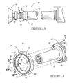
- FIGURE 1 is a side view of the driveline assembly in accordance with the teachings of the present invention; and
- FIGURE 2 is an exploded view of the damper assembly attached to a slip yoke in accordance with the teachings of the present invention.
-
- The following description of the preferred embodiment is merely exemplary in nature, and is in no way intended to limit the invention or its application or uses.
- Referring in particular to the drawings, a driveline assembly installed in a motor vehicle is generally illustrated by
reference numeral 10. Typically, thedriveline assembly 10 is adapted to transmit rotational power from anengine system 14 to a plurality of drive wheels (not shown). Typically, thedriveline assembly 10 comprises adriveshaft 12 that transfers the rotational power through thedriveline assembly 10. Thedriveshaft 12 is conventional in the art and preferably is an internallysplined driveshaft 12. - In order to connect the
driveshaft 12 from theengine 14 to the wheels, thedriveline assembly 10 typically includes at least oneslip yoke assembly 16. Due to the rotational and axial movement of thedriveshaft 12,driveline assembly 10 exhibits noise and vibrations. In order to reduce the noise and dampen the vibrations of thedriveline assembly 10, adamper assembly 22 is incorporated in thedriveline assembly 10. In the present invention, thedamper assembly 22 is a part of theslip yoke assembly 16. Thedamper assembly 22 functions to dampen the vibration of thedriveline assembly 10, such that the vibrations are not substantially transferred to the vehicular parts of the motor vehicle. In addition, thedamper assembly 22 is also capable of being adjusted such that the modulus of thedriveline assembly 10 can be altered to minimize the vibrations in the vehicle. - As shown in FIGURE 1, the
driveshaft 12 is connected to aslip yoke assembly 16, preferably thedriveshaft 12 is welded to theslip yoke assembly 16. Alternatively other suitable means may be employed to connect theslip yoke assembly 16 to thedriveshaft 12. Theslip yoke assembly 16 is conventional in the art and includes ayoke 18 and auniversal cross joint 20. Theyoke 18 is typically connected to atubular end 17 that is attached to an engine shaft (not shown). - Referring in particular to FIGURE 2, in order to minimize the vibrations of the
driveshaft 12 during the operation of a motor vehicle, adamper assembly 22 is installed in theslip yoke assembly 16. Thedamper assembly 22 of the present invention comprises adamper ring 24 that is fastened to theslip yoke assembly 16. Preferably, thedamper ring 24 is annular and is provided with acentral opening 26. In order to facilitate the fastening of thedamper ring 24, a plurality ofholes universal cross joint 20. A corresponding set ofopenings damper ring 24. Preferably, thedamper ring 24 is fastened to theslip yoke assembly 16 by means ofbolts bolts openings damper ring 24 and fasten thedamper ring 24 to theslip yoke assembly 16. Alternatively, other means such as welding may be used to fasten thedamper ring 24 to theslip yoke assembly 16. Preferably, thedamper ring 24 is made of cast iron such that thedamper ring 24 add more mass to thedamper assembly 22 and functions to more effectively dampen the vibrations of thedriveline assembly 10. - As shown in FIGURE 2, the
damper ring 24 preferably comprises anouter housing 30 and aninner housing 32. Agap 34 is defined between theouter housing 30 and theinner housing 32. In order to facilitate the damping of the vibrations of thedriveline assembly 10, thegap 34 between theouter housing 30 and theinner housing 32 is filled with magnetorheological (MR)elastomer 50. The MR elastomer, therefore holds theouter housing 30 and theinner housing 32. The MR elastomer is conventional in the art and may comprise a suitable gel as an elastomer of natural rubber. The gel or elastomer has particulate materials embedded therein. Preferred particulates are those that are magnetisable by means of an applied magnetic field, that is, particulates having paramagnetic, ferromagnetic, or ferromagnetic properties. The size of the magnetisable particles used can vary widely, such as, for example, from 10 nanometres to several millimeters. Preferably, therecess 34 is filled with the MR elastomer rubber ring where the characteristics of theMR elastomer 50 may be altered by changing the magnetic field applied to thedamper assembly 22. - In order to vary the magnetic field and hence the modulus of the
MR elastomer 50, theinner housing 32 is provided with a plurality ofopenings openings openings MR elastomer 50. - The
openings magnetic bolts bolts inner housing 32. - The
magnetic bolts damper assembly 22. The magnetic field will subsequently result in the alignment of the particulates in the MR elastomer. The alignment of the particulates in the MR elastomer will determine the modulus of the MR elastomer. The modulus of the MR elastomer can be varied either by axially turning the magnetic bolts towards the inner housing or by axially turning the magnetic bolts away from the inner housing. Therefore, by turning the magnetized bolts towards theinner housing 32, the modulus of the MR elastomer will increase and thereby increasing the stiffness of the MR elastomer. Alternatively, the modulus of the MR elastomer may be reduced by turning the magnetic bolts away from theinner housing 32. - The present invention also provides for a method of tuning the
damper assembly 22 to different frequencies to effectively dampen the vibrations of thedriveline assembly 10. In particular thedamper assembly 22 is first tuned to a baseline frequency. Next vehicle testing is performed to natural frequency of the driveline assembly for a particular speed. Also, the torsional mode is determined of thedriveline assembly 10. Themagnetized bolts damper assembly 22 with the natural frequency of the drive line assembly. Further, the damper assembly can be tuned to different frequency by merely adjusting thebolts driveline assembly 10, as onedamper assembly 22 can be substantially tuned to damper the vibrations of the driveline assembly. - As any person skilled in the art will recognize from the previous description and from the figures and claims, modifications and changes can be made to the preferred embodiment of the invention without departing from the scope of the invention as defined in the following claims.
Claims (23)
- A driveline assembly installed in a motor vehicle comprising:a tubular shaft having a first end and a second end, wherein the shaft transfers rotational energy from an engine to the wheels of the motor vehicle;a slip yoke assembly having a yoke member and an annular member attached to the yoke member, wherein the yoke member is rotatably coupled to the shaft;a damper assembly fastened to the annular member of the slip yoke assembly;
wherein the damper assembly comprises an outer housing, an inner housing and a recess defined between the outer housing and the inner housing;
such that the inner housing defines a first opening;a magnetorheological elastomer housing located in the recess between the outer housing and inner housing; andat least one magnetic means received in the first opening such that a axial movement of the at least one magnetic means changes the modulus of the magnetorheological elastomer, and thus changes the frequency of the slip yoke. - A driveline assembly according to claim 1, wherein the inner housing further comprises a second opening for receiving fasteners to connect the damper assembly to the slip yoke assembly.
- A driveline assembly according to claim 2, wherein the fasteners are bolts.
- A driveline assembly according to any one of claims 1 to 3, wherein the axial movement of the magnetic means comprises rotating the magnetic means towards the inner housing.
- A driveline assembly according to claim 4, wherein rotating the magnetic means towards the inner housing increases the modulus of the magnetorheological elastomer.
- The A driveline assembly according to any one of claims 1 to 3, wherein the axial movement of the magnetic means comprises rotating the magnetic means away from the inner housing.
- A driveline assembly according to claim 6, wherein rotating the magnetic means away from the inner housing decreases the modulus of the magnetorheological elastomer.
- A driveline assembly according to any one of claims 1 to 7, wherein the magnetic means for varying the modulus of the magnetorheological elastomer is magnetic bolts.
- A driveline assembly according to any one of claims 1 to 8, wherein the inner housing is made of cast metal.
- A driveline assembly according to any one of claims 1 to 9, wherein the outer housing is made of cast metal.
- A damper assembly fastenable to a slip yoke assembly in a drive line assembly of a motor vehicle comprising:an outer housing;an inner housing wherein the inner housing has a first opening;a gap defined between the inner housing and the outer housing;a magnetorheological elastomer housed in the gap between the outer housing and inner housing; andat least one magnetic means received in the first opening such that a axial movement of the magnetic means changes the modulus of the magnetorheological elastomer.
- A damper assembly according to claim 11, wherein the inner housing comprises a second opening for receiving fasteners to connect the damper assembly to the slip yoke assembly.
- A damper assembly according to claim 12, wherein the fasteners are bolts.
- A damper assembly according to any one of claim 11 to claim 13, wherein the axial movement of the magnetic means comprises rotating the magnetic means towards the inner housing.
- A damper assembly according to claim 14, wherein rotating the magnetic means towards the inner housing increases the modulus of the magnetorheological elastomer.
- A damper assembly according to any one of claim 11 to claim 15, wherein the axial movement of the magnetic means comprises rotating the magnetic means away from the inner housing.
- A damper assembly according to claim 16, wherein rotating the magnetic means away from the inner housing decreases the modulus of the magnetorheological elastomer.
- A damper assembly according to any one of claim 11 to claim 17, wherein the magnetic means for varying the modulus of the elastomer are magnetic bolts.
- A damper assembly according to any one of claim 11 to claim 18, wherein the inner housing is made of cast metal.
- A damper assembly according to any one of claim 11 to claim 19, wherein the outer housing is made of cast metal.
- A method of damping the vibrations of a driveline assembly in a motor vehicle, the method comprising the steps of:providing a damper assembly;fastening the damper assembly to a slip yoke assembly, wherein the damper assembly has an inner housing and an outer housing; providing a gap between the inner housing and the outer housing;
defining a first opening in the inner housing;providing a magnetorheological elastomer in the recess between the inner housing and the outer housing; andproviding at least one magnetic means in the first opening such that rotation of the at least one magnetic means changes the modulus of the magnetorheological elastomer. - A method according to claim 21 further comprising the steps of:measuring a natural frequency of the driveline assembly of the motor vehicle;measuring a torsional mode of the driveline assembly;tuning the damper assembly to a baseline frequency;moving the at least one magnetic means either towards the inner housing or away from the inner housing such that the baseline frequency of the damper assembly matches the natural frequency of the driveline assembly.
- A method according to claim 21 wherein the at least one magnetic means is magnetic bolts.
Applications Claiming Priority (2)
| Application Number | Priority Date | Filing Date | Title |
|---|---|---|---|
| US932593 | 2001-08-17 | ||
| US09/932,593 US6623364B2 (en) | 2001-08-17 | 2001-08-17 | Tunable slip yoke damper assembly |
Publications (1)
| Publication Number | Publication Date |
|---|---|
| EP1284373A1 true EP1284373A1 (en) | 2003-02-19 |
Family
ID=25462559
Family Applications (1)
| Application Number | Title | Priority Date | Filing Date |
|---|---|---|---|
| EP02255099A Withdrawn EP1284373A1 (en) | 2001-08-17 | 2002-07-22 | Tunable slip yoke damper assembly |
Country Status (2)
| Country | Link |
|---|---|
| US (1) | US6623364B2 (en) |
| EP (1) | EP1284373A1 (en) |
Cited By (2)
| Publication number | Priority date | Publication date | Assignee | Title |
|---|---|---|---|---|
| CN105508498A (en) * | 2015-12-19 | 2016-04-20 | 东北大学 | Method for restricting rotation of rotary machinery rotor |
| US11673445B2 (en) * | 2019-07-30 | 2023-06-13 | Continental Automotive Systems, Inc. | Powertrain proactive damping system using magneto rheological materials |
Families Citing this family (9)
| Publication number | Priority date | Publication date | Assignee | Title |
|---|---|---|---|---|
| US7022023B2 (en) * | 2002-04-30 | 2006-04-04 | Don Guo | Integrated driveline flange torsional damper |
| DE102006020650B3 (en) * | 2006-05-02 | 2007-08-23 | Thyssenkrupp Presta Ag | Steering column for a motor vehicle |
| US7942229B2 (en) * | 2008-10-28 | 2011-05-17 | American Axle & Manufacturing, Inc. | Dual-tuned vibration damper and method for damping vibrations in a power transmission system using a dual-tuned vibration damper |
| US20110121223A1 (en) * | 2009-11-23 | 2011-05-26 | Gm Global Technology Operations, Inc. | Magnetorheological fluids and methods of making and using the same |
| KR101129302B1 (en) * | 2010-03-11 | 2012-03-26 | 인하대학교 산학협력단 | Device for controlling vibration of hollow shaft in using magneto-rheological elastomer |
| US10465557B2 (en) | 2015-09-01 | 2019-11-05 | Rolls-Royce North American Technologies, Inc. | Magnetic squeeze film damper system for a gas turbine engine |
| US20190011013A1 (en) * | 2017-07-07 | 2019-01-10 | GM Global Technology Operations LLC | Active vibration damper for a vehicle driveline component |
| CN116025660B (en) * | 2023-03-10 | 2024-09-10 | 重庆大学 | Passive mechanical continuous adjustable magneto-rheological damper |
| CN119652232B (en) * | 2024-12-26 | 2025-06-17 | 深圳市江博仕新能源有限公司 | High-efficient light guide installing support with solar photovoltaic board matches |
Citations (5)
| Publication number | Priority date | Publication date | Assignee | Title |
|---|---|---|---|---|
| US4023438A (en) * | 1975-03-13 | 1977-05-17 | Metzeler Kautschuk Ag | Torsional vibration damper |
| US4114472A (en) * | 1975-08-02 | 1978-09-19 | Daimler-Benz Aktiengesellschaft | Installation for vibration damping in drive connection of motor vehicles |
| DE3917330A1 (en) * | 1989-05-27 | 1990-11-29 | Continental Ag | Torsional vibration balancer system - has flywheel mass radially inside it and hub and shaft, has rubber spring with fibres and threads inserted |
| EP0784163A1 (en) * | 1996-01-11 | 1997-07-16 | Ford Motor Company Limited | Variable stiffness bushing using magnetorheological elastomers |
| EP1083361A1 (en) * | 1999-09-09 | 2001-03-14 | Carl Schenck Ag | Torsional vibration damper |
Family Cites Families (16)
| Publication number | Priority date | Publication date | Assignee | Title |
|---|---|---|---|---|
| US2683825A (en) * | 1952-09-12 | 1954-07-13 | Danly Mach Specialties Inc | Eddy-current clutch mounting means |
| GB789031A (en) * | 1955-10-11 | 1958-01-15 | Wipac Dev Ltd | Improvements in and relating to permanent magnet alternators |
| US4452334A (en) | 1982-10-21 | 1984-06-05 | The United States Of America As Represented By The United States Department Of Energy | Tunable damper for an acoustic wave guide |
| US4733758A (en) | 1986-08-18 | 1988-03-29 | Lord Corporation | Tunable electrorheological fluid mount |
| US5286013A (en) | 1990-11-13 | 1994-02-15 | General Electric Company | Vibration damper assembly |
| JP3020307B2 (en) * | 1991-06-05 | 2000-03-15 | 株式会社シマノ | Brake mechanism for fishing reel |
| US5573088A (en) | 1994-05-10 | 1996-11-12 | Daniels; John J. | Controllable resistance device and force dampener, and vehicle utilizing the same |
| US5553514A (en) * | 1994-06-06 | 1996-09-10 | Stahl International, Inc. | Active torsional vibration damper |
| US5452957A (en) | 1994-11-22 | 1995-09-26 | Dana Corporation | Center bearing assembly including support member containing rheological fluid |
| US5542508A (en) | 1995-06-26 | 1996-08-06 | Illinois Tool Works Inc. | Fluid free damper |
| US5634853A (en) | 1995-12-27 | 1997-06-03 | Dana Corporation | Slip yoke assembly for vehicle driveshaft |
| US5941133A (en) | 1996-04-19 | 1999-08-24 | Eti Technologies Inc. | Torsional and translational vibration removing device |
| US5816587A (en) * | 1996-07-23 | 1998-10-06 | Ford Global Technologies, Inc. | Method and apparatus for reducing brake shudder |
| US5829319A (en) | 1996-10-04 | 1998-11-03 | Vibratech, Inc. | Magneto-rheological torsional vibration damper |
| DE19704517C2 (en) | 1997-02-06 | 2003-06-12 | Zf Sachs Ag | Torsional vibration damping device for damping torsional vibrations in a drive train |
| US5947238A (en) | 1997-03-05 | 1999-09-07 | Lord Corporation | Passive magnetorheological fluid device with excursion dependent characteristic |
-
2001
- 2001-08-17 US US09/932,593 patent/US6623364B2/en not_active Expired - Lifetime
-
2002
- 2002-07-22 EP EP02255099A patent/EP1284373A1/en not_active Withdrawn
Patent Citations (5)
| Publication number | Priority date | Publication date | Assignee | Title |
|---|---|---|---|---|
| US4023438A (en) * | 1975-03-13 | 1977-05-17 | Metzeler Kautschuk Ag | Torsional vibration damper |
| US4114472A (en) * | 1975-08-02 | 1978-09-19 | Daimler-Benz Aktiengesellschaft | Installation for vibration damping in drive connection of motor vehicles |
| DE3917330A1 (en) * | 1989-05-27 | 1990-11-29 | Continental Ag | Torsional vibration balancer system - has flywheel mass radially inside it and hub and shaft, has rubber spring with fibres and threads inserted |
| EP0784163A1 (en) * | 1996-01-11 | 1997-07-16 | Ford Motor Company Limited | Variable stiffness bushing using magnetorheological elastomers |
| EP1083361A1 (en) * | 1999-09-09 | 2001-03-14 | Carl Schenck Ag | Torsional vibration damper |
Cited By (3)
| Publication number | Priority date | Publication date | Assignee | Title |
|---|---|---|---|---|
| CN105508498A (en) * | 2015-12-19 | 2016-04-20 | 东北大学 | Method for restricting rotation of rotary machinery rotor |
| CN105508498B (en) * | 2015-12-19 | 2018-01-02 | 东北大学 | A kind of method for suppressing oscillation of rotary machine rotor |
| US11673445B2 (en) * | 2019-07-30 | 2023-06-13 | Continental Automotive Systems, Inc. | Powertrain proactive damping system using magneto rheological materials |
Also Published As
| Publication number | Publication date |
|---|---|
| US6623364B2 (en) | 2003-09-23 |
| US20030036432A1 (en) | 2003-02-20 |
Similar Documents
| Publication | Publication Date | Title |
|---|---|---|
| US8028602B2 (en) | Active vibrational damper | |
| US6623364B2 (en) | Tunable slip yoke damper assembly | |
| JP3155280B2 (en) | Drive | |
| EP1056958B1 (en) | Electromagnetic clutch and pulley assembly | |
| US20020140145A1 (en) | Magneto-rheological steering damper | |
| CN107956839B (en) | A composite adjustable transmission system torsional vibration damping device with particle damping and electromagnetic damping | |
| CA2426066A1 (en) | Isolator for alternator pulley | |
| AU605182B2 (en) | Electromagnetic clutch with impact absorbing connector | |
| CN201561090U (en) | Driven frame type torsion vibration absorber of flywheel | |
| CN116557473A (en) | A dual-mass flywheel with variable inertia based on electromagnetic control | |
| KR101289750B1 (en) | Electromagnetic clutch for compressor | |
| US8136621B2 (en) | Dual-tuned vibration damper | |
| US5762558A (en) | Damper disc assemby and balance weight therefor | |
| CN103052821B (en) | Devices for transmitting torque for drive lines of motor vehicles | |
| US6668995B2 (en) | Variable inertia flywheel | |
| CN101076934B (en) | Pulley assembly connected to transmission mechanism | |
| AU599395B2 (en) | Electromagnetic clutch | |
| GB2388176A (en) | An integrated drive-line flange and torsional damper component | |
| Agrawal et al. | A bearing application using magnetorheological fluids | |
| KR101360129B1 (en) | disc & hub assembly of electromagnetic clutch | |
| CN114537046B (en) | Counterweight structure arranged on driving half shaft | |
| JP2002295588A (en) | Torsional damper | |
| US6540056B1 (en) | Armature disk with friction material | |
| JPH05312224A (en) | Electromagnetic connecting device | |
| CN108317216B (en) | Torsional damper and clutch and vehicle using same |
Legal Events
| Date | Code | Title | Description |
|---|---|---|---|
| PUAI | Public reference made under article 153(3) epc to a published international application that has entered the european phase |
Free format text: ORIGINAL CODE: 0009012 |
|
| AK | Designated contracting states |
Designated state(s): AT BE BG CH CY CZ DE DK EE ES FI FR GB GR IE IT LI LU MC NL PT SE SK TR |
|
| AX | Request for extension of the european patent |
Extension state: AL LT LV MK RO SI |
|
| 17P | Request for examination filed |
Effective date: 20030507 |
|
| AKX | Designation fees paid |
Designated state(s): DE FR GB |
|
| STAA | Information on the status of an ep patent application or granted ep patent |
Free format text: STATUS: THE APPLICATION IS DEEMED TO BE WITHDRAWN |
|
| 18D | Application deemed to be withdrawn |
Effective date: 20050201 |