EP1284347A1 - Throttle body - Google Patents
Throttle body Download PDFInfo
- Publication number
- EP1284347A1 EP1284347A1 EP01934352A EP01934352A EP1284347A1 EP 1284347 A1 EP1284347 A1 EP 1284347A1 EP 01934352 A EP01934352 A EP 01934352A EP 01934352 A EP01934352 A EP 01934352A EP 1284347 A1 EP1284347 A1 EP 1284347A1
- Authority
- EP
- European Patent Office
- Prior art keywords
- bore
- throttle valve
- throttle
- resin
- filler
- Prior art date
- Legal status (The legal status is an assumption and is not a legal conclusion. Google has not performed a legal analysis and makes no representation as to the accuracy of the status listed.)
- Withdrawn
Links
Images











Classifications
-
- F—MECHANICAL ENGINEERING; LIGHTING; HEATING; WEAPONS; BLASTING
- F02—COMBUSTION ENGINES; HOT-GAS OR COMBUSTION-PRODUCT ENGINE PLANTS
- F02D—CONTROLLING COMBUSTION ENGINES
- F02D9/00—Controlling engines by throttling air or fuel-and-air induction conduits or exhaust conduits
- F02D9/08—Throttle valves specially adapted therefor; Arrangements of such valves in conduits
- F02D9/10—Throttle valves specially adapted therefor; Arrangements of such valves in conduits having pivotally-mounted flaps
- F02D9/1075—Materials, e.g. composites
- F02D9/108—Plastics
-
- F—MECHANICAL ENGINEERING; LIGHTING; HEATING; WEAPONS; BLASTING
- F02—COMBUSTION ENGINES; HOT-GAS OR COMBUSTION-PRODUCT ENGINE PLANTS
- F02D—CONTROLLING COMBUSTION ENGINES
- F02D9/00—Controlling engines by throttling air or fuel-and-air induction conduits or exhaust conduits
- F02D9/08—Throttle valves specially adapted therefor; Arrangements of such valves in conduits
- F02D9/10—Throttle valves specially adapted therefor; Arrangements of such valves in conduits having pivotally-mounted flaps
- F02D9/1005—Details of the flap
- F02D9/101—Special flap shapes, ribs, bores or the like
-
- F—MECHANICAL ENGINEERING; LIGHTING; HEATING; WEAPONS; BLASTING
- F02—COMBUSTION ENGINES; HOT-GAS OR COMBUSTION-PRODUCT ENGINE PLANTS
- F02D—CONTROLLING COMBUSTION ENGINES
- F02D9/00—Controlling engines by throttling air or fuel-and-air induction conduits or exhaust conduits
- F02D9/08—Throttle valves specially adapted therefor; Arrangements of such valves in conduits
- F02D9/10—Throttle valves specially adapted therefor; Arrangements of such valves in conduits having pivotally-mounted flaps
- F02D9/1035—Details of the valve housing
-
- F—MECHANICAL ENGINEERING; LIGHTING; HEATING; WEAPONS; BLASTING
- F02—COMBUSTION ENGINES; HOT-GAS OR COMBUSTION-PRODUCT ENGINE PLANTS
- F02D—CONTROLLING COMBUSTION ENGINES
- F02D9/00—Controlling engines by throttling air or fuel-and-air induction conduits or exhaust conduits
- F02D9/08—Throttle valves specially adapted therefor; Arrangements of such valves in conduits
- F02D9/10—Throttle valves specially adapted therefor; Arrangements of such valves in conduits having pivotally-mounted flaps
- F02D9/107—Manufacturing or mounting details
-
- F—MECHANICAL ENGINEERING; LIGHTING; HEATING; WEAPONS; BLASTING
- F16—ENGINEERING ELEMENTS AND UNITS; GENERAL MEASURES FOR PRODUCING AND MAINTAINING EFFECTIVE FUNCTIONING OF MACHINES OR INSTALLATIONS; THERMAL INSULATION IN GENERAL
- F16K—VALVES; TAPS; COCKS; ACTUATING-FLOATS; DEVICES FOR VENTING OR AERATING
- F16K1/00—Lift valves or globe valves, i.e. cut-off apparatus with closure members having at least a component of their opening and closing motion perpendicular to the closing faces
- F16K1/16—Lift valves or globe valves, i.e. cut-off apparatus with closure members having at least a component of their opening and closing motion perpendicular to the closing faces with pivoted closure-members
- F16K1/18—Lift valves or globe valves, i.e. cut-off apparatus with closure members having at least a component of their opening and closing motion perpendicular to the closing faces with pivoted closure-members with pivoted discs or flaps
- F16K1/22—Lift valves or globe valves, i.e. cut-off apparatus with closure members having at least a component of their opening and closing motion perpendicular to the closing faces with pivoted closure-members with pivoted discs or flaps with axis of rotation crossing the valve member, e.g. butterfly valves
- F16K1/222—Shaping of the valve member
-
- B—PERFORMING OPERATIONS; TRANSPORTING
- B29—WORKING OF PLASTICS; WORKING OF SUBSTANCES IN A PLASTIC STATE IN GENERAL
- B29C—SHAPING OR JOINING OF PLASTICS; SHAPING OF MATERIAL IN A PLASTIC STATE, NOT OTHERWISE PROVIDED FOR; AFTER-TREATMENT OF THE SHAPED PRODUCTS, e.g. REPAIRING
- B29C45/00—Injection moulding, i.e. forcing the required volume of moulding material through a nozzle into a closed mould; Apparatus therefor
- B29C45/0005—Injection moulding, i.e. forcing the required volume of moulding material through a nozzle into a closed mould; Apparatus therefor using fibre reinforcements
-
- B—PERFORMING OPERATIONS; TRANSPORTING
- B29—WORKING OF PLASTICS; WORKING OF SUBSTANCES IN A PLASTIC STATE IN GENERAL
- B29L—INDEXING SCHEME ASSOCIATED WITH SUBCLASS B29C, RELATING TO PARTICULAR ARTICLES
- B29L2031/00—Other particular articles
- B29L2031/748—Machines or parts thereof not otherwise provided for
- B29L2031/7506—Valves
Definitions
- the present invention relates to a throttle valve made of resin used in a throttle body made of resin.
- a conventional throttle body one of the components of an intake system, is manufactured by aluminum die casting. Efforts have been made in recent years to provide lightweight, low-cost throttle bodies by forming throttle bodies of resins.
- the bore of a throttle body must be formed so that the gap between the bore wall defining the bore of the throttle body and a throttle valve placed in the bore of the throttle body is in the range of 80 to 100 ⁇ m.
- the bore of a conventional throttle body formed by die casting is finished by machining to form the bore in a desired accuracy. If a resin throttle body can be formed such that its bore is formed in an accuracy that insures the gap in the aforesaid range, machining is unnecessary.
- the roundness of the bore after molding shrinkage, the roundness of the throttle valve (hereinafter, roundness is used to represent variations in diameter), and errors in the inside diameter of the bore must be equal to those of an aluminum throttle valve formed by die casting. It is necessary to prevent the interference between the bore wall and the throttle valve, and an excessive increase in the gap between the throttle body and the throttle valve due to thermal deformation caused by the variation of temperature between a very low temperature and a high temperature exceeding 100°C.
- a method of preventing irregular deformation proposed in JP-A No. 169473/1998 places filler in an orientation in a bore part of a throttle body defining a bore. It is considered that the gap can be reduced when a metal throttle valve formed by machining is placed in such a bore part.
- the throttle valve must be formed of resin to omit a machining process.
- the throttle body and the throttle valve can be formed of resins respectively having similar coefficients of linear expansion, respectively, and hence the initial gap between the bore wall and the throttle valve can be substantially maintained.
- the throttle valve is formed of a resin having a thermal conductivity lower than those of metals, it is possible to prevent freezing that occurs in metal throttle valves during operation.
- both the throttle body and the throttle valve are formed of the same resin containing the same amount of filler, the throttle body and the throttle valve have different coefficients of linear expansion, respectively, and deform by different quantities of deformation, respectively due to the difference between the throttle body and the throttle valve in the orientation of the filler. Consequently, there is the possibility that the throttle valve interferes with the bore wall, and the gap between the bore wall and the throttle valve increases excessively.
- Recent internal combustion engines have a tendency to reduce idle throttle valve opening to reduce idle speed.
- idle throttle valve opening is reduced, the possibility that contaminants, such as carbon contained in the recirculated exhaust gas, and oils contained in the blowby gas, adhere to the periphery of the throttle valve increases. If those contaminants deposited on the throttle valve are solidified by the heat of the internal combustion engine, the throttle valve is locked to the bore wall and, in the worst case, the throttle valve will not move even if the accelerator pedal is operated.
- a second object of the present invention is to reduce the roundness of a bore after molding shrinkage and to reduce the gap between a throttle valve and the bore.
- a third object of the present invention is to prevent the fixation of a throttle valve by solid deposits including carbon and oils.
- a filler contained in a resin is oriented in a circumferential direction to make the linear expansion coefficient of a throttle valve in a radial direction approach that of a bore by making the thermal deformation of the throttle valve approach that of the bore to prevent the aforesaid interference and the enlargement of the gap.
- a throttle body comprises: a throttle shaft extended substantially diametrically across an intake cylinder (bore); and a throttle valve fixed to the throttle shaft and contained in the bore; wherein the bore and the throttle valve are made of a resin containing filler, and the difference between circumferential deformation of the bore and radial deformation of the throttle valve is in the range of 0 to 40 ⁇ m at temperatures in the range of -40°C to 120°C.
- a throttle body comprises: an intake cylinder (bore); and a throttle valve; wherein the throttle valve and the bore are formed of resins containing filler, the difference between the linear expansion coefficient of the throttle valve and that of the bore is in the range of 0 to 4 ⁇ 10 -6 /°C.
- the fillers in the bore and the throttle valve are oriented in substantially the same direction.
- the fillers are randomly oriented in the bore and the throttle valve.
- the throttle valve is provided with circumferential grooves or ribs, and the filler is substantially circumferentially oriented.
- the throttle valve is formed by sandwiching an aggregate formed by circumferentially arranging the filler between resin layers.
- the throttle valve is made of a resin different in filler content from that forming the bore to make the radial linear expansion coefficient of the throttle valve nearly equal to the circumferential linear expansion coefficient of the bore.
- At least a peripheral part of the throttle valve facing the bore wall of the bore is made of a resin containing a fluorocarbon resin or is coated with a fluorocarbon resin.
- a throttle body comprises: a throttle shaft extended substantially diametrically across an intake cylinder (bore); and a throttle valve fixed to the throttle shaft and contained in the bore; wherein the bore is made of a resin, and an annular rib of a fixed or continuously changing width, or parts of such an annular rib are formed in a part, corresponding to the throttle shaft, of the bore to counterbalance the effect of sinks due to bosses.
- minimum thickness is 2/3 of maximum thickness or below.
- ribs are formed in parts of the bore, around the throttle shaft such that the product of maximum height and thickness is in the range of 15 to 40% of the height and the mean thickness of the bosses, and the product of minimum height and thickness is in the range of 20 to 80% of the product of maximum height and thickness.
- the bore is provided in a part thereof with a rib capable of limiting the roundness (diameter) of a part of the bore in the range of ⁇ 5 mm along the center axis of the bore from a position corresponding to the throttle shaft to 80 ⁇ m or below.
- the ribs are formed in the parts of the intake cylinder defining the bore around the throttle shaft to reduce the roundness of the bore after mold shrinkage.
- the present invention adds an additive to the resin to suppress the adhesion of carbon and oils to the throttle valve.
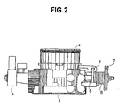
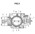
- a throttle body 3 has a throttle valve 1 contained in a space surrounded by a bore wall 4a of a bore 4, and a throttle shaft 5.
- the throttle valve 1 is fastened to the throttle shaft 5 with screws 22.
- the throttle shaft 5 is extended substantially diametrically across the bore 4.
- a throttle lever 7 is connected to one end of the throttle shaft 5.
- a return spring 6 is extended between the throttle lever 7 and a stopper 8.
- a throttle-valve position sensor 9 is attached to the other end of the throttle shaft 5.
- the throttle lever 7 When the driver depresses an accelerator pedal, not shown, the throttle lever 7 is moved and the throttle shaft 5 is moved accordingly to open the throttle valve 1.
- the throttle valve 1 When the force applied to the accelerator pedal is removed, the throttle valve 1 is closed by the resilience of the return spring 6.
- the gap between the circumference 1a of the throttle valve 1 and the bore wall 4a is, for example, in the range of 80 to 100 ⁇ m to reduce idle speed, fuel consumption and noise during idling. This gap enables the smooth movement of the throttle valve 1. In Fig. 3, the gap is exaggerated to facilitate understanding.
- Fig. 4 is a schematic view of assistance in explaining a method of molding a common disk, in which a filler is indicated at 10, a disk is indicated at 11 and a runner a is indicated at 12. A resin flows through the runner 12 to a position corresponding to the center of the disk-shaped part 11. As shown in Fig. 4, the filler 10 is oriented radially from the center when the thickness of the disk-shaped part 11 is small. The filler 10 is enlarged in Fig. 4 to facilitate recognizing the direction of orientation.
- Fig. 5 is a schematic view of assistance in explaining a method of molding a cylindrical part. Gates symmetrical with respect to a circumferential direction are formed to improve roundness. Shown in Fig. 5 are a cylindrical part 13, a gate 14 and a runner b 15. In this case, the filler 10 extends in a flowing direction and is generally axially oriented. It is expected that circumferential and radial coefficients of thermal deformation are large, an axial thermal deformation is small.
- Fig. 22 show measured coefficients of linear expansion of a cylindrical part and a disk-shaped part made of a resin containing the filler 10.
- the circumferential linear expansion coefficient of the cylindrical part is 1.6 times the axial linear expansion coefficient of the same, and the circumferential linear expansion coefficient of the disk-shaped part is 1.4 times the radial linear expansion coefficient of the same, which substantiates the aforesaid expectation.
- the cylindrical part is a bore
- the disk-shaped part is a throttle valve.
- the circumferential linear expansion coefficient of the cylindrical part, and the radial linear expansion coefficient of the disk-shaped part are related with the gap.
- the circumferential linear expansion coefficient of the cylindrical part 28.8 ⁇ 10 -6 /°C
- the radial linear expansion coefficient of the disk-shaped part 18.8 ⁇ 10 -6 /°C.
- the difference between the respective deformations of the bore and the throttle vale must be smaller than 80 ⁇ m.
- the deformation difference of 80 ⁇ m corresponds to a difference of about 8 ⁇ 10 -6 /°C in linear expansion coefficient when the inside diameter is 60 mm and the working temperature range is -40 to 120°C.
- the difference between the respective coefficients of linear expansion of the both must not be greater than about 8 ⁇ 10 -6 /°C. More preferably, in view of changes in roundness, it is desirable that the deformation difference is 40 ⁇ m or below.
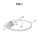
- Fig. 1 is a typical view of a throttle valve 1 in a first embodiment according to the present invention. Shown in Fig. 1 are a throttle valve 16, some of grooves 17 arranged on concentric circles, and holes 24 for attaching the throttle valve 16 to a shaft 5.
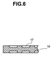
- Fig. 6 is a sectional view taken on line A-A in Fig. 1.
- Filler 2 can be oriented mostly in a circumferential direction by arranging the grooves 17 on concentric circles.
- the grooves 17 are arranged zigzag in this embodiment to make a resin flow through thin parts of each groove without fail.
- the radial flow of the resin is disturbed to make the extension of the filler in radial directions difficult, and the probability of the filler extending in a circumferential direction increases.
- the filler can be more randomly oriented by changing the depth, size and pitches of the grooves 17.
- the linear expansion coefficient of the throttle valve 1 is close to that of the bore 4.
- the difference in linear expansion coefficient between the throttle valve 1 and the bore 4 can be made smaller than that when the filler is radially oriented in the throttle valve (valve) by randomly orienting the filler, which is within the scope of the present invention.
- the radial linear expansion coefficient of the throttle valve can be made to approach that of the bore 4 to suppress the variation of the gap between the throttle valve 16 and the bore 4 according to temperature variation.
- the throttle valve 16 in this embodiment can be easily made by injecting a thermoplastic resin into a cavity of a mold provided with protrusions corresponding to the grooves.
- Minimum thicknesses t of the disk-shaped parts, which are associated with these depths of the grooves, are 2.0 mm, 1.5 mm and 1.0 mm, respectively.
- the thickness ratio t/t 0 is measured on the horizontal axis, and the linear expansion coefficient ratio ⁇ / ⁇ 0 , i.e., the ratio of the linear expansion coefficient ⁇ of the throttle valve to the linear expansion coefficient ⁇ 0 of the bore is measured on vertical axis.
- the effect of the groves is significant and the linear expansion coefficient ratio ⁇ / ⁇ 0 approaches 1 when the thickness ratio t/t 0 is smaller than 2/3; that is, the respective linear expansion coefficients of the disk-shaped part and the bore approaches each other.
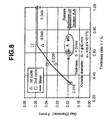
- Fig. 8 shows calculated gaps between the disk-shaped part and the bore in the temperature range of -40 to 120°C.
- the gap is 49 ⁇ m when the disk-shaped part is not provided with any grooves.
- the gap is as small as 18 ⁇ m when the disk-shaped part is provided with grooves of 1 mm in depth.
- the gap can be limited to 40 ⁇ m or below (0 to 40 ⁇ m) when the temperature of the disk-shaped part is in the temperature range of -40 to 120°C by forming grooves in the disk-shaped part such that the minimum thickness is 1/2 of the original thickness or below. This corresponds to the linear expansion coefficient difference of about 4 ⁇ 10 -6 /°C (0 to 4 ⁇ 10 -6 /°C) when the inside diameter is 60 mm.
- the linear expansion coefficient of of 23.7 ⁇ 10 -6 /°C of the disk-shaped part in this embodiment is greater than the linear expansion coefficient of 18.1 ⁇ 10 -6 /°C of a disk-shaped part shown in Fig. 22 and is near the linear expansion coefficient of 28.8 ⁇ 10 -6 /°C of the bore. It is inferred that such a fact is the result of increase of part not subject to the influence of shearing with a wall surface resulting from increase of the thickness in the range of 1.5 to 3.0 mm and increase of the ratio of circumferentially oriented fibers.
- the practical throttle valve 16 is in contact with the bore 4 in a position inclined at several degrees to the axis of the bore and not perpendicular to the axis of the bore. Therefore, the practical throttle valve 16 is not a perfectly circular disk, is an elliptic plate and is tapered.
- the mold is made so as to conform the shape of the throttle valve 16.
- the grooves 17 are formed in the opposite surfaces, the grooves 17 may be formed only in one of the opposite surfaces for the same effect. However, when the grooves 17 is formed only in one of the opposite surfaces, measures to prevent the warp of the throttle valve, such as heating different parts of the mold at different temperatures, respectively, must be taken. Although the grooves 17 are arranged zigzag in this embodiment, the grooves may be radially arranged. The throttle valve may be provided with concentric circular grooves. The grooves 17 may be formed only in a peripheral part for the same effect.
- the throttle valve 1 is bent around the throttle shaft by a negative pressure during idling.
- the throttle valve 11 since the throttle valve 11 is not perpendicular to the axis of the bore and is inclined at an angle to the axis of the bore, a half part of the throttle valve closer to the engine is bent so as to recede from the bore wall. The other half part of the throttle valve farther from the engine is bent so as to come into the bore wall. Consequently, the throttle valve and the bore gall and, there is the possibility, in the worst case, that the throttle valve becomes uncontrollable.
- ribs are formed on the half part of the throttle valve farther from the engine (right-hand half part in Fig. 9) instead of the grooves so that the filler are circumferentially oriented.
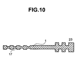
- Shown in Fig. 10 are grooves 17 and ribs 23.
- Fig. 10 is a sectional view taken on line A-A in Fig. 9.
- Most part of the filler 10 is circumferentially oriented in the half part provided with ribs 23 of the throttle valve shown in Fig. 10. Therefore, the linear expansion coefficient of the throttle valve 1 can be made near or substantially equal to that of the bore.
- the strength of the throttle valve 1 can be increased and, at the same time, the difference in linear expansion coefficient between the throttle valve and the bore can be reduced to a value not greater than the predetermined value, which can solve the problem with galling of the throttle valve 1 and bore 4.
- ribs may be formed either on both or one of the opposite surfaces. If the ribs are formed only on one of the surfaces, flow resistance can be reduced by forming protrusions on the side of the engine.
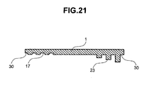
- Fig. 21 shows another section of a throttle valve corresponding to the section taken on line A-A in Fig. 9. Shown in Fig. 21 are grooves 17 and ribs 23. The ribs are formed in a right half part of the throttle valve such that the height of the rib nearer to the circumference is greater than that of the rib farther from the circumference to enhance the bending rigidity of the rib. The adhesion of carbon and oils to a peripheral part 30 can be avoided without forming any rib in the peripheral part 30.
- Possible materials as the filler to be contained in the resin used in this embodiment are, for example, glass fibers, carbon fibers, boron fibers, aramid fibers, carbon silicate fibers, alumina fibers and potassium titanate (K n O ⁇ nTiO 2 ) whiskers.
- Fig. 11 is a typical view of assistance in explaining a method of manufacturing a throttle valve 1 in a second embodiment according to the present invention
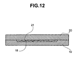
- Fig. 12 is a sectional view of a mold to be used in manufacturing the throttle valve 1.
- an aggregate 18 formed by circumferentially arranging filler 2, a lower mold 19, and an upper mold 20.
- the aggregate of the filler 2 is placed in a recess formed in the lower mold 19, a thermosetting resin is poured in the recess to impregnate the filler 2 with the thermosetting resin, the lower mold 19 and the upper mold 20 are joined together, and the mold is heated to set the thermosetting resin.
- the filler 2 is arranged circumferentially.
- the linear expansion coefficient of the second embodiment similarly to that of the first embodiment, can be made to approach the linear expansion coefficient of the bore 4, so that it is possible to prevent the variation of the gap between the throttle valve 1 and the bore 4 according to the variation of temperature.
- a filling member formed by arranging strings of the filler 2 in concentric circles or in a spiral may be used. Even a filling member like a fabric formed by weaving threads of the filler 2 is somewhat effective.
- a throttle valve 1 having the same properties can be manufactured by using a cold-setting resin, a photocurable resin or a thermoplastic resin instead of the thermosetting resin. If a photocurable resin is used, the upper mold 20 must be a glass mold.
- the radial linear expansion coefficient of a throttle valve 1 can be made to approach the circumferential linear expansion coefficient of a bore 4 by another method that forms the throttle valve 1 of a resin having a filler content different from that of a resin forming the bore 4.
- the linear expansion coefficient of a resin having a small filler content is large.
- the linear expansion coefficient of the throttle valve 1 in this embodiment can be made to approach the circumferential linear expansion coefficient of the bore 4 by forming the throttle valve 1 of a resin having a small filler content. Consequently, the variation of the gap between the throttle valve 1 and the bore 4 according to the variation of temperature can be suppressed.
- the radial linear expansion coefficient of the throttle valve can be made to approach the circumferential linear expansion coefficient of the bore by forming the throttle valve and the bore of different resins, respectively.
- Fig. 13 shows a model of assistance in explaining the postmolding shrinkage that occurs after injection molding of a throttle body in a fourth embodiment according to the present invention.
- a bore 4 bearing housings 25 for housing bearings supporting a throttle shaft, and a through holes 26 through which the throttle shaft is extended.
- the bore is 50 mm in diameter and 100 mm in height
- the housing is 20 mm in diameter and 10 mm in height
- the through holes are 10 mm in diameter
- the bore has a wall thickness of 2 mm.
- PEI polyetherimide
- mica ULTEM 3452 made by GE Plastics
- Fig. 14 shows the results of the analysis.
- Broken lines 27 indicate, in an enlarged view, the position of the bore corresponding to the position of the center of the throttle shaft after shrinkage.
- the shrinkage of a part corresponding to the bearing housings is large and the bore has a laterally elongate elliptic shape.
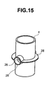
- annular rib 28 of 2 mm in thickness and 10 mm in width was formed around a part corresponding to the center of the throttle shaft.
- Fig. 16 shows the results of analysis performed using the model shown in Fig. 15.
- Broken lines 29 indicate, in an enlarged view, the position of the bore corresponding to the position of the center of the throttle shaft after shrinkage.
- the shrinkage of the bore is different from that of the bore shown in Fig. 14, and a part corresponding to the bearing housings and the bore has a longitudinally elongate elliptic shape. It was inferred that such shrinkage occurred because the shrinkage of the annular rib is greater than a part corresponding to the bearing housings.
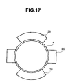
- Fig. 17 shows a bore provided with partial ribs.
- the partial ribs narrow ranges of shrinking effect of the ribs.
- Fig. 18 shows a rib having a narrow width.
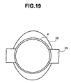
- Fig. 19 shows ribs having a continuously changing width. The roundness of the bore can be greatly improved by these ribs.
- Fig. 20 is a diagram of assistance in explaining the dependence of deformation due to postmolding shrinkage on the shape of the rib, in which the ratio h/h 0 , i.e., the ratio of the maximum width h of the rib to the height h 0 of the boss, is measured on the horizontal axis, and the ratio hb/h, i.e., the ratio of minimum width hb of the rib to the maximum width h of the rib, is measured on the vertical axis.
- the ratio h/h 0 i.e., the ratio of the maximum width h of the rib to the height h 0 of the boss
- the ratio hb/h i.e., the ratio of minimum width hb of the rib to the maximum width h of the rib
- the bore is deformed in a laterally elongate elliptic shape, in a longitudinally elongate elliptic shape, and in a nearly square shape when any ribs are not formed, when a large rib is formed, and when a rib having a comparatively narrow, uniform width is formed, respectively.
- the roundness after molding shrinkage is the smallest in the vicinity of the boundaries of those three deformation modes.
- the roundness is 80 ⁇ m or below in a range where the maximum width is in the range of 15 to 40% of the height of the boss, and the minimum width is in the range of 20 to 80% of the maximum width.
- the respective mean wall thicknesses of the rib and the bore are substantially equal.
- sinks are dependent not only on the width of the rib and the height of the boss, but also on the volume.
- a deformation mode will be similar to a case where the width of the rib and the height of the boss are multiplied by the wall thickness.
- the same effect as that available when the rib and the boss have the same wall thickness is expected when the rib is formed such that the product of the maximum width and wall thickness of the rib is in the range of 15 to 40% of the product of the height and the mean wall thickness of the boss, and the product of the minimum width and wall thickness of the rib is in the range of 20 to 80% of the product of the maximum width and wall thickness of the rib.
- the roundness Since the throttle valve is inclined at an angle in the range of 5° to 7° when closed, the roundness must be 80 ⁇ m or below in a range of ⁇ 5 mm along the center axis of the bore from a position corresponding to the throttle shaft.
- the results of the analysis showed that the roundness is substantially 80 ⁇ m or below in the aforesaid ranges.
- ribs may be formed in two or more layers at positions around the center of the throttle shaft. Since the rib enhances the rigidity of the bore, the wall thickness of the bore may be reduced.
- the adhesion of oils or carbon can be prevented by forming the throttle valve 1 of a resin capable of preventing the adhesion of oils, carbon or an adhesive substance containing oils and carbon. More concretely, water repellency can be increased and the adhesion of oils or carbon to the throttle valve can be prevented by adding a fluorocarbon resin, such as PTFE (polytetrafluoroethylene resin) to the resin. Formation of a peripheral part of the throttle valve 1 of a resin containing a fluorocarbon resin by two-color molding provides a similar effect. Alternatively, coating the surface of the throttle valve 1 with a fluorocarbon resin provides a similar effect.
- PTFE polytetrafluoroethylene resin
- the bore 4 and the throttle valve 1 are substantially the same in linear expansion coefficient, the gap between the bore wall 4a and the circumference 1a of the throttle valve 1 can be kept uniform, and the interference between the bore 4 and the throttle valve 1 can be avoided.
- the roundness of a part of the bore around the throttle shaft after molding shrinkage can be reduced.
- the gap between the bore wall 4a and the circumference 1a of the throttle valve during idling can be limited to a very small value, so that a high-performance resin throttle body that permits only a small air leakage can be obtained.
- the adhesion of carbon and oils to the throttle valve 1 can be suppressed by adding an additive to the resin and, consequently, the faulty operation of the throttle valve 1 can be obviated.
- the present invention is applicable to the throttle body included in the intake system of an automobile, and is particularly of service when the bore and the throttle valve of the throttle body are made of resins.
Landscapes
- Engineering & Computer Science (AREA)
- General Engineering & Computer Science (AREA)
- Mechanical Engineering (AREA)
- Chemical & Material Sciences (AREA)
- Combustion & Propulsion (AREA)
- Manufacturing & Machinery (AREA)
- Control Of Throttle Valves Provided In The Intake System Or In The Exhaust System (AREA)
- Lift Valve (AREA)
Abstract
Efforts have been made in recent years to provide
lightweight, low-cost throttle bodies by forming throttle
bodies of resins. The bore of a throttle body must be
formed so that the gap between the bore of the throttle
body and a throttle valve placed in the bore is in the
range of 80 to 100 µm. Even if the bore and the throttle
valve are made of the same resin, the bore and the
throttle valve have different linear expansion
coefficients, respectively, when the bore and the throttle
valve differ from each other in the orientation of a
filler contained in the resin and, consequently, the bore
and the throttle valve differ from each other in thermal
deformation. Roundness can be deteriorated by molding
shrinkage. Therefore, there is the possibility that the
bore and the throttle valve interfere with each other and
an excessively large gap is formed. The present invention
circumferentially orients filler contained in a resin
forming a throttle valve to make the radial linear
expansion coefficient of the throttle valve substantially
equal to that of a bore 4. Grooves 17 are formed on
concentric circles in the throttle valve to orient filler
2 circumferentially. A throttle valve provided with
circumferentially oriented filler can be formed by
impregnating an aggregate formed by circumferentially
arranging the filler with a resin and curing the resin. A
rib 28 is formed in a part near a throttle shaft to
control molding shrinkage so that the roundness of the
bore 4 is small.
Description
The present invention relates to a throttle valve
made of resin used in a throttle body made of resin.
Research and development activities have been made
to reduce the weight of automobiles for the reduction of
fuel consumption. A conventional throttle body, one of
the components of an intake system, is manufactured by
aluminum die casting. Efforts have been made in recent
years to provide lightweight, low-cost throttle bodies by
forming throttle bodies of resins.
The bore of a throttle body must be formed so that
the gap between the bore wall defining the bore of the
throttle body and a throttle valve placed in the bore of
the throttle body is in the range of 80 to 100 µm. The
bore of a conventional throttle body formed by die casting
is finished by machining to form the bore in a desired
accuracy. If a resin throttle body can be formed such
that its bore is formed in an accuracy that insures the
gap in the aforesaid range, machining is unnecessary. The
roundness of the bore after molding shrinkage, the
roundness of the throttle valve (hereinafter, roundness is
used to represent variations in diameter), and errors in
the inside diameter of the bore must be equal to those of
an aluminum throttle valve formed by die casting. It is
necessary to prevent the interference between the bore
wall and the throttle valve, and an excessive increase in
the gap between the throttle body and the throttle valve
due to thermal deformation caused by the variation of
temperature between a very low temperature and a high
temperature exceeding 100°C.
A method of preventing irregular deformation
proposed in JP-A No. 169473/1998 places filler in an
orientation in a bore part of a throttle body defining a
bore. It is considered that the gap can be reduced when a
metal throttle valve formed by machining is placed in such
a bore part.
However, in view of cost reduction, the throttle
valve must be formed of resin to omit a machining process.
When both a throttle body having a bore and a throttle
valve to be placed in the bore are formed of resins, the
throttle body and the throttle valve can be formed of
resins respectively having similar coefficients of linear
expansion, respectively, and hence the initial gap between
the bore wall and the throttle valve can be substantially
maintained. When the throttle valve is formed of a resin
having a thermal conductivity lower than those of metals,
it is possible to prevent freezing that occurs in metal
throttle valves during operation. Even if both the
throttle body and the throttle valve are formed of the
same resin containing the same amount of filler, the
throttle body and the throttle valve have different
coefficients of linear expansion, respectively, and deform
by different quantities of deformation, respectively due
to the difference between the throttle body and the
throttle valve in the orientation of the filler.
Consequently, there is the possibility that the throttle
valve interferes with the bore wall, and the gap between
the bore wall and the throttle valve increases excessively.
Recent internal combustion engines have a tendency
to reduce idle throttle valve opening to reduce idle speed.
When idle throttle valve opening is reduced, the
possibility that contaminants, such as carbon contained in
the recirculated exhaust gas, and oils contained in the
blowby gas, adhere to the periphery of the throttle valve
increases. If those contaminants deposited on the
throttle valve are solidified by the heat of the internal
combustion engine, the throttle valve is locked to the
bore wall and, in the worst case, the throttle valve will
not move even if the accelerator pedal is operated.
It is a first object of the present invention to
form a throttle body such that the thermal deformation of
the bore wall of the throttle body is substantially equal
to that of a throttle valve at temperatures in the range
of a very low temperature to a temperature exceeding 100°C,
the gap between the bore wall and the throttle valve is at
the same level as the gap between the bore wall of a
conventional throttle body and a conventional throttle
valve, and to provide a low-cost, high-performance
throttle body.
A second object of the present invention is to
reduce the roundness of a bore after molding shrinkage and
to reduce the gap between a throttle valve and the bore.
A third object of the present invention is to
prevent the fixation of a throttle valve by solid deposits
including carbon and oils.
To solve the foregoing problems, according to the
present invention, a filler contained in a resin is
oriented in a circumferential direction to make the linear
expansion coefficient of a throttle valve in a radial
direction approach that of a bore by making the thermal
deformation of the throttle valve approach that of the
bore to prevent the aforesaid interference and the
enlargement of the gap.
To solve the foregoing problems, a throttle body
according to the present invention comprises: a throttle
shaft extended substantially diametrically across an
intake cylinder (bore); and a throttle valve fixed to the
throttle shaft and contained in the bore; wherein the bore
and the throttle valve are made of a resin containing
filler, and the difference between circumferential
deformation of the bore and radial deformation of the
throttle valve is in the range of 0 to 40 µm at
temperatures in the range of -40°C to 120°C.
To solve the foregoing problems, a throttle body
according to the present invention comprises: an intake
cylinder (bore); and a throttle valve; wherein the
throttle valve and the bore are formed of resins
containing filler, the difference between the linear
expansion coefficient of the throttle valve and that of
the bore is in the range of 0 to 4×10⁻⁶/°C.
To solve the foregoing problems, in the throttle
body according to the present invention, the fillers in
the bore and the throttle valve are oriented in
substantially the same direction.
To solve the foregoing problems, in the throttle
body according to the present invention, the fillers are
randomly oriented in the bore and the throttle valve.
To solve the foregoing problems, in the throttle
body according to the present invention, the throttle
valve is provided with circumferential grooves or ribs,
and the filler is substantially circumferentially oriented.
To solve the foregoing problems, in the throttle
body according to the present invention, the throttle
valve is formed by sandwiching an aggregate formed by
circumferentially arranging the filler between resin
layers.
To solve the foregoing problems, in the throttle
valve according to the present invention, the throttle
valve is made of a resin different in filler content from
that forming the bore to make the radial linear expansion
coefficient of the throttle valve nearly equal to the
circumferential linear expansion coefficient of the bore.
To solve the foregoing problems, in the throttle
body according to the present invention, at least a
peripheral part of the throttle valve facing the bore wall
of the bore is made of a resin containing a fluorocarbon
resin or is coated with a fluorocarbon resin.
To solve the foregoing problems, a throttle body
according to the present invention comprises: a throttle
shaft extended substantially diametrically across an
intake cylinder (bore); and a throttle valve fixed to the
throttle shaft and contained in the bore; wherein the bore
is made of a resin, and an annular rib of a fixed or
continuously changing width, or parts of such an annular
rib are formed in a part, corresponding to the throttle
shaft, of the bore to counterbalance the effect of sinks
due to bosses.
To solve the foregoing problems, in the throttle
body according to the present invention, minimum thickness
is 2/3 of maximum thickness or below.
To solve the foregoing problems, in the throttle
body according to the present invention, ribs are formed
in parts of the bore, around the throttle shaft such that
the product of maximum height and thickness is in the
range of 15 to 40% of the height and the mean thickness of
the bosses, and the product of minimum height and
thickness is in the range of 20 to 80% of the product of
maximum height and thickness.
To solve the foregoing problems, in the throttle
body according to the present invention, the bore is
provided in a part thereof with a rib capable of limiting
the roundness (diameter) of a part of the bore in the
range of ±5 mm along the center axis of the bore from a
position corresponding to the throttle shaft to 80 µm or
below.
According to the present invention, the ribs are
formed in the parts of the intake cylinder defining the
bore around the throttle shaft to reduce the roundness of
the bore after mold shrinkage.
The present invention adds an additive to the resin
to suppress the adhesion of carbon and oils to the
throttle valve.
Preferred embodiments of the present invention will
be described hereinafter with reference to the
accompanying drawings.
Referring to Figs. 2 and 3, a throttle body 3 has a
throttle valve 1 contained in a space surrounded by a bore
wall 4a of a bore 4, and a throttle shaft 5. The throttle
valve 1 is fastened to the throttle shaft 5 with screws 22.
The throttle shaft 5 is extended substantially
diametrically across the bore 4. A throttle lever 7 is
connected to one end of the throttle shaft 5. A return
spring 6 is extended between the throttle lever 7 and a
stopper 8. A throttle-valve position sensor 9 is attached
to the other end of the throttle shaft 5.
When the driver depresses an accelerator pedal, not
shown, the throttle lever 7 is moved and the throttle
shaft 5 is moved accordingly to open the throttle valve 1.
When the force applied to the accelerator pedal is removed,
the throttle valve 1 is closed by the resilience of the
return spring 6. In a state where the throttle valve 1 is
closed, the gap between the circumference 1a of the
throttle valve 1 and the bore wall 4a is, for example, in
the range of 80 to 100 µm to reduce idle speed, fuel
consumption and noise during idling. This gap enables the
smooth movement of the throttle valve 1. In Fig. 3, the
gap is exaggerated to facilitate understanding.
When the throttle body 3 is heated by the heat
generated by the engine, part of the gap between the
circumference 1a of the throttle valve and the bore wall
4a decreases, and the throttle valve 1 bites into the bore
wall. This phenomenon is liable to occur mostly during
idling.
The linear expansion coefficient of a resin
containing a fibrous filler in a direction parallel to the
extending direction of the filler is small, and that of
the same in a direction perpendicular to the extending
direction of the filler is large. Fig. 4 is a schematic
view of assistance in explaining a method of molding a
common disk, in which a filler is indicated at 10, a disk
is indicated at 11 and a runner a is indicated at 12. A
resin flows through the runner 12 to a position
corresponding to the center of the disk-shaped part 11.
As shown in Fig. 4, the filler 10 is oriented radially
from the center when the thickness of the disk-shaped part
11 is small. The filler 10 is enlarged in Fig. 4 to
facilitate recognizing the direction of orientation.
Therefore, it is expected that radial thermal deformation
is smaller than circumferential thermal deformation. Fig.
5 is a schematic view of assistance in explaining a method
of molding a cylindrical part. Gates symmetrical with
respect to a circumferential direction are formed to
improve roundness. Shown in Fig. 5 are a cylindrical part
13, a gate 14 and a runner b 15. In this case, the filler
10 extends in a flowing direction and is generally axially
oriented. It is expected that circumferential and radial
coefficients of thermal deformation are large, an axial
thermal deformation is small. Fig. 22 show measured
coefficients of linear expansion of a cylindrical part and
a disk-shaped part made of a resin containing the filler
10.
The circumferential linear expansion coefficient of
the cylindrical part is 1.6 times the axial linear
expansion coefficient of the same, and the circumferential
linear expansion coefficient of the disk-shaped part is
1.4 times the radial linear expansion coefficient of the
same, which substantiates the aforesaid expectation.
Suppose that the cylindrical part is a bore, and the disk-shaped
part is a throttle valve. Then, the
circumferential linear expansion coefficient of the
cylindrical part, and the radial linear expansion
coefficient of the disk-shaped part are related with the
gap. There is a large difference between the
circumferential linear expansion coefficient of the
cylindrical part of 28.8×10⁻⁶/°C and the radial linear
expansion coefficient of the disk-shaped part of 18.8×10⁻⁶/°C.
When the inside diameter is 60 mm, a difference
between sizes in the working temperature range of -40 to
120°C is 96 µm. Thus, it is most important to make equal
the coefficients of linear expansion of the both. In this
case, the difference between the respective deformations
of the bore and the throttle vale must be smaller than 80
µm. The deformation difference of 80 µm corresponds to a
difference of about 8×10⁻⁶/°C in linear expansion
coefficient when the inside diameter is 60 mm and the
working temperature range is -40 to 120°C. Thus, to
prevent galling of the bore and throttle valve, the
difference between the respective coefficients of linear
expansion of the both must not be greater than about 8×10⁻⁶/°C.
More preferably, in view of changes in roundness, it
is desirable that the deformation difference is 40 µm or
below.
In this embodiment, a method of increasing the
radial linear expansion coefficient of the throttle valve
1, which is easier to deal with than the throttle body 3,
has been devised. Preferred embodiments of the present
invention will be described with reference to the
accompanying drawings.
Fig. 1 is a typical view of a throttle valve 1 in a
first embodiment according to the present invention.
Shown in Fig. 1 are a throttle valve 16, some of grooves
17 arranged on concentric circles, and holes 24 for
attaching the throttle valve 16 to a shaft 5. Fig. 6 is a
sectional view taken on line A-A in Fig. 1.
Filler 2 can be oriented mostly in a
circumferential direction by arranging the grooves 17 on
concentric circles. The grooves 17 are arranged zigzag in
this embodiment to make a resin flow through thin parts of
each groove without fail. Thus, the radial flow of the
resin is disturbed to make the extension of the filler in
radial directions difficult, and the probability of the
filler extending in a circumferential direction increases.
The filler can be more randomly oriented by
changing the depth, size and pitches of the grooves 17.
When the filler is oriented mostly in a circumferential
direction, it is desirable that the linear expansion
coefficient of the throttle valve 1 is close to that of
the bore 4. The difference in linear expansion
coefficient between the throttle valve 1 and the bore 4
can be made smaller than that when the filler is radially
oriented in the throttle valve (valve) by randomly
orienting the filler, which is within the scope of the
present invention.
Consequently, as mentioned above, the radial linear
expansion coefficient of the throttle valve can be made to
approach that of the bore 4 to suppress the variation of
the gap between the throttle valve 16 and the bore 4
according to temperature variation.
The throttle valve 16 in this embodiment can be
easily made by injecting a thermoplastic resin into a
cavity of a mold provided with protrusions corresponding
to the grooves.
Fig. 7 shows the coefficients α of linear expansion
of four types of disk-shaped parts of a thickness of t0 =
3 mm and an outside diameter of 60 mm, respectively
provided with grooves of depths of 0.5 mm, 0.75 mm and 1.0
mm. Minimum thicknesses t of the disk-shaped parts, which
are associated with these depths of the grooves, are 2.0
mm, 1.5 mm and 1.0 mm, respectively. The thickness ratio
t/t0 is measured on the horizontal axis, and the linear
expansion coefficient ratio α/α0, i.e., the ratio of the
linear expansion coefficient α of the throttle valve to
the linear expansion coefficient α0 of the bore is
measured on vertical axis. The effect of the groves is
significant and the linear expansion coefficient ratio
α/α0 approaches 1 when the thickness ratio t/t0 is smaller
than 2/3; that is, the respective linear expansion
coefficients of the disk-shaped part and the bore
approaches each other.
Fig. 8 shows calculated gaps between the disk-shaped
part and the bore in the temperature range of -40
to 120°C. The gap is 49 µm when the disk-shaped part is
not provided with any grooves. The gap is as small as 18
µm when the disk-shaped part is provided with grooves of 1
mm in depth. In this embodiment, the gap can be limited
to 40 µm or below (0 to 40 µm) when the temperature of the
disk-shaped part is in the temperature range of -40 to
120°C by forming grooves in the disk-shaped part such that
the minimum thickness is 1/2 of the original thickness or
below. This corresponds to the linear expansion
coefficient difference of about 4×10⁻⁶/°C (0 to 4×10⁻⁶/°C)
when the inside diameter is 60 mm.
The linear expansion coefficient of of 23.7×10⁻⁶/°C
of the disk-shaped part in this embodiment is greater than
the linear expansion coefficient of 18.1×10⁻⁶/°C of a disk-shaped
part shown in Fig. 22 and is near the linear
expansion coefficient of 28.8×10⁻⁶/°C of the bore. It is
inferred that such a fact is the result of increase of
part not subject to the influence of shearing with a wall
surface resulting from increase of the thickness in the
range of 1.5 to 3.0 mm and increase of the ratio of
circumferentially oriented fibers.
To prevent galling of the throttle valve and bore 4,
the practical throttle valve 16 is in contact with the
bore 4 in a position inclined at several degrees to the
axis of the bore and not perpendicular to the axis of the
bore. Therefore, the practical throttle valve 16 is not a
perfectly circular disk, is an elliptic plate and is
tapered. The mold is made so as to conform the shape of
the throttle valve 16.
Although the grooves 17 are formed in the opposite
surfaces, the grooves 17 may be formed only in one of the
opposite surfaces for the same effect. However, when the
grooves 17 is formed only in one of the opposite surfaces,
measures to prevent the warp of the throttle valve, such
as heating different parts of the mold at different
temperatures, respectively, must be taken. Although the
grooves 17 are arranged zigzag in this embodiment, the
grooves may be radially arranged. The throttle valve may
be provided with concentric circular grooves. The grooves
17 may be formed only in a peripheral part for the same
effect.
The throttle valve 1 is bent around the throttle
shaft by a negative pressure during idling. As mentioned
above, since the throttle valve 11 is not perpendicular to
the axis of the bore and is inclined at an angle to the
axis of the bore, a half part of the throttle valve closer
to the engine is bent so as to recede from the bore wall.
The other half part of the throttle valve farther from the
engine is bent so as to come into the bore wall.
Consequently, the throttle valve and the bore gall and,
there is the possibility, in the worst case, that the
throttle valve becomes uncontrollable.
As shown in Fig. 9, ribs are formed on the half
part of the throttle valve farther from the engine (right-hand
half part in Fig. 9) instead of the grooves so that
the filler are circumferentially oriented. Shown in Fig.
10 are grooves 17 and ribs 23. Thus, the reduction of the
thickness due to the formation of the grooves is avoided
and the rigidity of the half part is increased. Fig. 10
is a sectional view taken on line A-A in Fig. 9. Most
part of the filler 10 is circumferentially oriented in the
half part provided with ribs 23 of the throttle valve
shown in Fig. 10. Therefore, the linear expansion
coefficient of the throttle valve 1 can be made near or
substantially equal to that of the bore. Consequently,
the strength of the throttle valve 1 can be increased and,
at the same time, the difference in linear expansion
coefficient between the throttle valve and the bore can be
reduced to a value not greater than the predetermined
value, which can solve the problem with galling of the
throttle valve 1 and bore 4.
The ribs may be formed either on both or one of the
opposite surfaces. If the ribs are formed only on one of
the surfaces, flow resistance can be reduced by forming
protrusions on the side of the engine. Fig. 21 shows
another section of a throttle valve corresponding to the
section taken on line A-A in Fig. 9. Shown in Fig. 21 are
grooves 17 and ribs 23. The ribs are formed in a right
half part of the throttle valve such that the height of
the rib nearer to the circumference is greater than that
of the rib farther from the circumference to enhance the
bending rigidity of the rib. The adhesion of carbon and
oils to a peripheral part 30 can be avoided without
forming any rib in the peripheral part 30.
Possible materials as the filler to be contained in
the resin used in this embodiment are, for example, glass
fibers, carbon fibers, boron fibers, aramid fibers, carbon
silicate fibers, alumina fibers and potassium titanate
(KnO·nTiO2) whiskers.
Fig. 11 is a typical view of assistance in
explaining a method of manufacturing a throttle valve 1 in
a second embodiment according to the present invention,
and Fig. 12 is a sectional view of a mold to be used in
manufacturing the throttle valve 1. There are shown an
aggregate 18 formed by circumferentially arranging filler
2, a lower mold 19, and an upper mold 20. The aggregate
of the filler 2 is placed in a recess formed in the lower
mold 19, a thermosetting resin is poured in the recess to
impregnate the filler 2 with the thermosetting resin, the
lower mold 19 and the upper mold 20 are joined together,
and the mold is heated to set the thermosetting resin. In
the throttle valve 1 in the second embodiment, the filler
2 is arranged circumferentially. The linear expansion
coefficient of the second embodiment, similarly to that of
the first embodiment, can be made to approach the linear
expansion coefficient of the bore 4, so that it is
possible to prevent the variation of the gap between the
throttle valve 1 and the bore 4 according to the variation
of temperature.
Although the aggregate of the filler 2 is used in
the second embodiment, a filling member formed by
arranging strings of the filler 2 in concentric circles or
in a spiral may be used. Even a filling member like a
fabric formed by weaving threads of the filler 2 is
somewhat effective.
A throttle valve 1 having the same properties can
be manufactured by using a cold-setting resin, a
photocurable resin or a thermoplastic resin instead of the
thermosetting resin. If a photocurable resin is used, the
upper mold 20 must be a glass mold.
The radial linear expansion coefficient of a
throttle valve 1 can be made to approach the
circumferential linear expansion coefficient of a bore 4
by another method that forms the throttle valve 1 of a
resin having a filler content different from that of a
resin forming the bore 4. Generally, the linear expansion
coefficient of a resin having a small filler content is
large. The linear expansion coefficient of the throttle
valve 1 in this embodiment can be made to approach the
circumferential linear expansion coefficient of the bore 4
by forming the throttle valve 1 of a resin having a small
filler content. Consequently, the variation of the gap
between the throttle valve 1 and the bore 4 according to
the variation of temperature can be suppressed.
The radial linear expansion coefficient of the
throttle valve can be made to approach the circumferential
linear expansion coefficient of the bore by forming the
throttle valve and the bore of different resins,
respectively.
Fig. 13 shows a model of assistance in explaining
the postmolding shrinkage that occurs after injection
molding of a throttle body in a fourth embodiment
according to the present invention. There are shown a
bore 4, bearing housings 25 for housing bearings
supporting a throttle shaft, and a through holes 26
through which the throttle shaft is extended. The bore is
50 mm in diameter and 100 mm in height, the housing is 20
mm in diameter and 10 mm in height, the through holes are
10 mm in diameter, and the bore has a wall thickness of 2
mm.
Flow, holding and warp during injection molding
were analyzed using this model and general-purpose resin
flow analyzing software (MOLDFLOW). A PEI
(polyetherimide) containing, as filler, 25% glass fibers
and 20% mica (ULTEM 3452 made by GE Plastics) was used.
Fig. 14 shows the results of the analysis. Broken
lines 27 indicate, in an enlarged view, the position of
the bore corresponding to the position of the center of
the throttle shaft after shrinkage. As obvious from Fig.
14, the shrinkage of a part corresponding to the bearing
housings is large and the bore has a laterally elongate
elliptic shape.
To form this part in a shape having a satisfactory
roundness, an annular rib 28 of 2 mm in thickness and 10
mm in width was formed around a part corresponding to the
center of the throttle shaft. Fig. 16 shows the results
of analysis performed using the model shown in Fig. 15.
Broken lines 29 indicate, in an enlarged view, the
position of the bore corresponding to the position of the
center of the throttle shaft after shrinkage. As obvious
from Fig. 16, the shrinkage of the bore is different from
that of the bore shown in Fig. 14, and a part
corresponding to the bearing housings and the bore has a
longitudinally elongate elliptic shape. It was inferred
that such shrinkage occurred because the shrinkage of the
annular rib is greater than a part corresponding to the
bearing housings.
It is known from the foregoing results that the
roundness of the bore after shrinkage can be improved by
properly determining the shape of the annular rib. Fig.
17 shows a bore provided with partial ribs. The partial
ribs narrow ranges of shrinking effect of the ribs. Fig.
18 shows a rib having a narrow width. Fig. 19 shows ribs
having a continuously changing width. The roundness of
the bore can be greatly improved by these ribs.
Fig. 20 is a diagram of assistance in explaining
the dependence of deformation due to postmolding shrinkage
on the shape of the rib, in which the ratio h/h0, i.e.,
the ratio of the maximum width h of the rib to the height
h0 of the boss, is measured on the horizontal axis, and
the ratio hb/h, i.e., the ratio of minimum width hb of the
rib to the maximum width h of the rib, is measured on the
vertical axis. The bore is deformed in a laterally
elongate elliptic shape, in a longitudinally elongate
elliptic shape, and in a nearly square shape when any ribs
are not formed, when a large rib is formed, and when a rib
having a comparatively narrow, uniform width is formed,
respectively. The roundness after molding shrinkage is
the smallest in the vicinity of the boundaries of those
three deformation modes. The roundness is 80 µm or below
in a range where the maximum width is in the range of 15
to 40% of the height of the boss, and the minimum width is
in the range of 20 to 80% of the maximum width. In Fig.
20, the respective mean wall thicknesses of the rib and
the bore are substantially equal. It is considered that
sinks are dependent not only on the width of the rib and
the height of the boss, but also on the volume. When the
rib and the boss differ from each other in wall thickness,
a deformation mode will be similar to a case where the
width of the rib and the height of the boss are multiplied
by the wall thickness. The same effect as that available
when the rib and the boss have the same wall thickness is
expected when the rib is formed such that the product of
the maximum width and wall thickness of the rib is in the
range of 15 to 40% of the product of the height and the
mean wall thickness of the boss, and the product of the
minimum width and wall thickness of the rib is in the
range of 20 to 80% of the product of the maximum width and
wall thickness of the rib.
Since the throttle valve is inclined at an angle in
the range of 5° to 7° when closed, the roundness must be
80 µm or below in a range of ±5 mm along the center axis
of the bore from a position corresponding to the throttle
shaft. The results of the analysis showed that the
roundness is substantially 80 µm or below in the aforesaid
ranges.
Although the rib is formed in one layer at a
position corresponding to the center of the throttle shaft
in this embodiment, ribs may be formed in two or more
layers at positions around the center of the throttle
shaft. Since the rib enhances the rigidity of the bore,
the wall thickness of the bore may be reduced.
The results of the analysis showed that the
roundness of a part corresponding to the throttle shaft is
improved scarcely when the rib is formed in axial range
other than an axial range corresponding to the boss.
Therefore, the rib must be formed in the axial range
corresponding to the boss.
The conception of the shape of the rib in this
embodiment applies also to a case where a resin and fiber
content different from those in this embodiment are used.
When an internal combustion engine, not shown,
operates, an exhaust gas and a blowby gas flow sometimes
from the internal combustion engine toward a throttle
valve 1. These gases contain carbon and oils. If the gap
between a throttle valve 1 and a bore wall 4a is narrow,
the carbon and the oils adhere to and solidify on a
peripheral part of the throttle valve 1 facing the bore
wall 4a. Consequently, the throttle valve 1 becomes
unmovable.
The adhesion of oils or carbon can be prevented by
forming the throttle valve 1 of a resin capable of
preventing the adhesion of oils, carbon or an adhesive
substance containing oils and carbon. More concretely,
water repellency can be increased and the adhesion of oils
or carbon to the throttle valve can be prevented by adding
a fluorocarbon resin, such as PTFE
(polytetrafluoroethylene resin) to the resin. Formation
of a peripheral part of the throttle valve 1 of a resin
containing a fluorocarbon resin by two-color molding
provides a similar effect. Alternatively, coating the
surface of the throttle valve 1 with a fluorocarbon resin
provides a similar effect.
According to the present invention, the bore 4 and
the throttle valve 1 are substantially the same in linear
expansion coefficient, the gap between the bore wall 4a
and the circumference 1a of the throttle valve 1 can be
kept uniform, and the interference between the bore 4 and
the throttle valve 1 can be avoided.
According to the present invention, the roundness
of a part of the bore around the throttle shaft after
molding shrinkage can be reduced.
Thus, the gap between the bore wall 4a and the
circumference 1a of the throttle valve during idling can
be limited to a very small value, so that a high-performance
resin throttle body that permits only a small
air leakage can be obtained.
According to the present invention, the adhesion of
carbon and oils to the throttle valve 1 can be suppressed
by adding an additive to the resin and, consequently, the
faulty operation of the throttle valve 1 can be obviated.
The present invention is applicable to the throttle
body included in the intake system of an automobile, and
is particularly of service when the bore and the throttle
valve of the throttle body are made of resins.
Claims (13)
- A throttle body comprising:wherein the bore and the throttle valve are made of a resin containing filler, and the difference between circumferential deformation of the bore and radial deformation of the throttle valve is in the range of 0 to 40 µm at temperatures in the range of -40°C to 120°C.a throttle shaft extended substantially diametrically across an intake cylinder (bore); anda throttle valve fixed to the throttle shaft and contained in the bore;
- The throttle body comprising:wherein the throttle valve and the bore are made of resins containing filler, and the difference between the linear expansion coefficient of the throttle valve and that of the bore is in the range of 0 to 4×10⁻⁶/°C.an intake cylinder (bore); anda throttle valve;
- The throttle body according to claim 1 or 2, wherein the fillers in the bore and the throttle valve are oriented in substantially the same direction.
- The throttle body according to claim 1 or 2, wherein the fillers are randomly oriented in the bore and the throttle valve.
- The throttle body according to claim 1 or 2, wherein the throttle valve is provided with circumferential grooves or ribs, and the filler is substantially circumferentially oriented in the throttle valve.
- The throttle body according to claim 1 or 2, wherein the throttle valve is formed by sandwiching an aggregate formed by circumferentially arranging the filler between resin layers.
- The throttle valve according to claim 1 or 2, wherein the throttle valve is made of a resin different in filler content from that forming the bore to make the radial linear expansion coefficient of the throttle valve nearly equal to the circumferential linear expansion coefficient of the bore.
- The throttle body according to claim 1 or 2, wherein at least a peripheral part of the throttle valve facing the bore wall of the bore is made of a resin containing a fluorocarbon resin or is coated with a fluorocarbon resin.
- A throttle body comprising:wherein the bore is made of a resin, and an annular rib of a fixed or continuously changing width, or parts of such an annular rib are formed in a part, corresponding to the throttle shaft, of the bore to counterbalance the effect of sinks due to bosses.a throttle shaft extended substantially diametrically across an intake cylinder (bore); anda throttle valve fixed to the throttle shaft and contained in the bore;
- The throttle body according to claim 1 or 2, wherein, a minimum thickness is 2/3 of a maximum thickness or below in the throttle valve stated in claim 5.
- The throttle body according to claim 9, wherein ribs are formed in parts of the bore provided with bosses, around the throttle shaft such that the product of maximum height and thickness is in the range of 15 to 40% of the height and the mean thickness of the bosses, and the product of minimum height and thickness is in the range of 20 to 80% of the product of maximum height and thickness.
- The throttle body according to claim 9, wherein a rib having a maximum width in the range of 15 to 40% of the height of the bosses and a minimum width in the range of 20 to 80% of the maximum width is formed in a part of the bore provided with the bosses, corresponding to the throttle shaft.
- The throttle body according to any one of claims 9, 11 and 12, wherein the bore is provided in a part thereof with a rib capable of limiting the roundness (diameter) of a part of the bore in the range of ±5 mm along the center axis of the bore from a position corresponding to the throttle shaft to 80 µm or below.
Priority Applications (1)
| Application Number | Priority Date | Filing Date | Title |
|---|---|---|---|
| EP08001843A EP2161432A1 (en) | 2000-05-25 | 2001-05-25 | Throttle body |
Applications Claiming Priority (5)
| Application Number | Priority Date | Filing Date | Title |
|---|---|---|---|
| JP2000159540 | 2000-05-25 | ||
| JP2000159540 | 2000-05-25 | ||
| JP2001105372A JP3971898B2 (en) | 2000-05-25 | 2001-04-04 | Throttle body |
| JP2001105372 | 2001-04-04 | ||
| PCT/JP2001/004404 WO2001090550A1 (en) | 2000-05-25 | 2001-05-25 | Throttle body |
Publications (2)
| Publication Number | Publication Date |
|---|---|
| EP1284347A1 true EP1284347A1 (en) | 2003-02-19 |
| EP1284347A4 EP1284347A4 (en) | 2007-07-25 |
Family
ID=26592861
Family Applications (2)
| Application Number | Title | Priority Date | Filing Date |
|---|---|---|---|
| EP08001843A Withdrawn EP2161432A1 (en) | 2000-05-25 | 2001-05-25 | Throttle body |
| EP01934352A Withdrawn EP1284347A4 (en) | 2000-05-25 | 2001-05-25 | BUTTERFLY BODY |
Family Applications Before (1)
| Application Number | Title | Priority Date | Filing Date |
|---|---|---|---|
| EP08001843A Withdrawn EP2161432A1 (en) | 2000-05-25 | 2001-05-25 | Throttle body |
Country Status (5)
| Country | Link |
|---|---|
| US (2) | US6986502B2 (en) |
| EP (2) | EP2161432A1 (en) |
| JP (1) | JP3971898B2 (en) |
| CN (1) | CN1444693A (en) |
| WO (1) | WO2001090550A1 (en) |
Cited By (1)
| Publication number | Priority date | Publication date | Assignee | Title |
|---|---|---|---|---|
| WO2008022876A1 (en) * | 2006-08-25 | 2008-02-28 | Mahle International Gmbh | Control valve for controlling a gas flow |
Families Citing this family (13)
| Publication number | Priority date | Publication date | Assignee | Title |
|---|---|---|---|---|
| DE10255339A1 (en) * | 2002-11-27 | 2004-06-09 | Siemens Ag | Process for the production of a throttle valve |
| WO2005116423A1 (en) * | 2004-05-31 | 2005-12-08 | Aisan Kogyo Kabushiki Kaisha | Molding method for throttle body and throttle body |
| JP4606829B2 (en) * | 2004-09-24 | 2011-01-05 | 本田技研工業株式会社 | Throttle valve device |
| JP2008063959A (en) * | 2006-09-05 | 2008-03-21 | Aisan Ind Co Ltd | Throttle device |
| JP5239179B2 (en) * | 2007-03-13 | 2013-07-17 | 独立行政法人産業技術総合研究所 | Back pressure valve |
| US20090000119A1 (en) * | 2007-06-26 | 2009-01-01 | Honeywell International, Inc. | Valve assemblies having valve flowbodies and methods of manufacturing |
| US8453621B2 (en) * | 2010-10-22 | 2013-06-04 | Magneti Marelli Powertrain Usa, Llc | Integrated throttle body for electronic fuel injection system and method of manufacture |
| USD681059S1 (en) * | 2012-08-22 | 2013-04-30 | Group-A Autosports, Inc. | Throttle body |
| JP5999252B2 (en) * | 2013-03-11 | 2016-09-28 | 株式会社島津製作所 | Flow path switching valve |
| US9938893B2 (en) * | 2014-12-22 | 2018-04-10 | MAGNETI MARELLI S.p.A. | Electromechanical actuator for an internal combustion engine provided with a conditioning circuit |
| KR101877132B1 (en) * | 2016-11-23 | 2018-07-10 | 주식회사 현대케피코 | Intake apparatus for engine |
| US20170159840A1 (en) * | 2017-02-22 | 2017-06-08 | Borgwarner Inc. | Coupling Device for a Valve Arrangement |
| KR20220123801A (en) * | 2021-03-02 | 2022-09-13 | 현대자동차주식회사 | Apparatus and method for controlling throttle valve heating in EGR system for preventing freezing |
Family Cites Families (16)
| Publication number | Priority date | Publication date | Assignee | Title |
|---|---|---|---|---|
| FR2687601A1 (en) * | 1992-02-26 | 1993-08-27 | Plastic Omnium Cie | Method of manufacturing a butterfly valve, device for implementing it and butterfly valve obtained by this method |
| AT410245B (en) * | 1993-07-14 | 2003-03-25 | Bosch Gmbh Robert | PLASTIC MOLDED BODY |
| DE4329527A1 (en) * | 1993-09-02 | 1995-03-09 | Mann & Hummel Filter | Throttle device |
| DE4334180A1 (en) * | 1993-10-07 | 1995-04-13 | Bosch Gmbh Robert | Throttling device |
| JP2824447B2 (en) * | 1993-12-10 | 1998-11-11 | 株式会社ミクニ | Multiple-integrated butterfly valve for intake control device of multi-cylinder internal combustion engine and apparatus for manufacturing the same |
| JPH0814069A (en) * | 1994-06-29 | 1996-01-16 | Nippondenso Co Ltd | Intake device for internal combustion engine |
| JP3787861B2 (en) * | 1995-07-14 | 2006-06-21 | 株式会社デンソー | Throttle valve device for internal combustion engine |
| JP3713694B2 (en) * | 1996-12-09 | 2005-11-09 | 株式会社デンソー | Throttle body and manufacturing method thereof |
| JPH10205359A (en) * | 1997-01-21 | 1998-08-04 | Nissan Motor Co Ltd | Air flow control device |
| JP3404254B2 (en) * | 1997-05-07 | 2003-05-06 | 株式会社日立製作所 | Engine throttle device |
| JP3670127B2 (en) * | 1997-12-22 | 2005-07-13 | 三菱エンジニアリングプラスチックス株式会社 | Shell of intake air control device for internal combustion engine |
| US5988131A (en) * | 1997-12-23 | 1999-11-23 | Ford Global Technologies, Inc. | Air intake system with composite throttle body |
| JP4178642B2 (en) * | 1998-02-04 | 2008-11-12 | 日産自動車株式会社 | Air flow control device and manufacturing method thereof |
| JPH11236830A (en) * | 1998-02-20 | 1999-08-31 | Nissan Motor Co Ltd | Resin throttle chamber |
| US6451238B1 (en) * | 1998-04-07 | 2002-09-17 | Honda Giken Kogyo Kabushiki Kaisha | Process for producing intake member of resin, and intake member of resin |
| US6354267B1 (en) * | 2000-03-28 | 2002-03-12 | Borgwarner Inc. | Injection molded throttle body |
-
2001
- 2001-04-04 JP JP2001105372A patent/JP3971898B2/en not_active Expired - Lifetime
- 2001-05-25 US US10/296,654 patent/US6986502B2/en not_active Expired - Fee Related
- 2001-05-25 CN CN01813268A patent/CN1444693A/en active Pending
- 2001-05-25 EP EP08001843A patent/EP2161432A1/en not_active Withdrawn
- 2001-05-25 WO PCT/JP2001/004404 patent/WO2001090550A1/en not_active Ceased
- 2001-05-25 EP EP01934352A patent/EP1284347A4/en not_active Withdrawn
-
2005
- 2005-11-14 US US11/273,905 patent/US7316385B2/en not_active Expired - Fee Related
Cited By (2)
| Publication number | Priority date | Publication date | Assignee | Title |
|---|---|---|---|---|
| WO2008022876A1 (en) * | 2006-08-25 | 2008-02-28 | Mahle International Gmbh | Control valve for controlling a gas flow |
| US8191861B2 (en) | 2006-08-25 | 2012-06-05 | Mahle International Gmbh | Control valve for controlling a gas flow |
Also Published As
| Publication number | Publication date |
|---|---|
| US20030106526A1 (en) | 2003-06-12 |
| US7316385B2 (en) | 2008-01-08 |
| EP1284347A4 (en) | 2007-07-25 |
| CN1444693A (en) | 2003-09-24 |
| JP3971898B2 (en) | 2007-09-05 |
| WO2001090550A1 (en) | 2001-11-29 |
| US6986502B2 (en) | 2006-01-17 |
| US20060060808A1 (en) | 2006-03-23 |
| JP2002047950A (en) | 2002-02-15 |
| EP2161432A1 (en) | 2010-03-10 |
Similar Documents
| Publication | Publication Date | Title |
|---|---|---|
| US7316385B2 (en) | Throttle body | |
| JP4163230B2 (en) | Throttle body manufacturing method and throttle body | |
| US5615861A (en) | Throttle device for an internal combustion engine | |
| US7047936B2 (en) | Throttle bodies and methods of manufacturing such throttle bodies | |
| JP4457115B2 (en) | Butterfly type valve device | |
| US20070240690A1 (en) | Fluid control valve | |
| CN100587243C (en) | intake control valve | |
| CN1054117A (en) | The manufacture method of engine throttle gate segment assembly and throttle blade thereof | |
| JP4103721B2 (en) | Method of forming throttle device for internal combustion engine | |
| JP4515075B2 (en) | Injection molding method for throttle device for internal combustion engine | |
| KR20020097272A (en) | Valve assembly for an internal combustion engine and method of manufacturing | |
| JP3713694B2 (en) | Throttle body and manufacturing method thereof | |
| JP2007146855A (en) | Throttle body | |
| JPH0751902B2 (en) | Throttle valve body | |
| JP4424179B2 (en) | Method of manufacturing throttle device for internal combustion engine | |
| JP2005180423A (en) | Throttle body and method of manufacturing the same | |
| JPH1162637A (en) | Intake device for internal combustion engine | |
| JP2006009683A (en) | Inlet throttle device for internal combustion engine | |
| JPH11294201A (en) | Intake air control device for internal combustion engine | |
| JP2005163546A (en) | Throttle body and its manufacturing method | |
| JPH0749784B2 (en) | Throttle assembly | |
| JPH03297614A (en) | Manufacture of fiber reinforced plastic valve lifter | |
| JP2005240572A (en) | Method of manufacturing throttle device for internal combustion engine | |
| JP2006002674A (en) | Body forming mold for throttle body |
Legal Events
| Date | Code | Title | Description |
|---|---|---|---|
| PUAI | Public reference made under article 153(3) epc to a published international application that has entered the european phase |
Free format text: ORIGINAL CODE: 0009012 |
|
| 17P | Request for examination filed |
Effective date: 20021212 |
|
| AK | Designated contracting states |
Designated state(s): AT BE CH CY DE DK ES FI FR GB GR IE IT LI LU MC NL PT SE TR |
|
| RBV | Designated contracting states (corrected) |
Designated state(s): DE FR GB |
|
| RIC1 | Information provided on ipc code assigned before grant |
Ipc: F02D 9/10 20060101AFI20011205BHEP |
|
| A4 | Supplementary search report drawn up and despatched |
Effective date: 20070626 |
|
| 17Q | First examination report despatched |
Effective date: 20070828 |
|
| STAA | Information on the status of an ep patent application or granted ep patent |
Free format text: STATUS: THE APPLICATION IS DEEMED TO BE WITHDRAWN |
|
| 18D | Application deemed to be withdrawn |
Effective date: 20080307 |