EP1284328A1 - Panel body using spiral wire - Google Patents
Panel body using spiral wire Download PDFInfo
- Publication number
- EP1284328A1 EP1284328A1 EP01932168A EP01932168A EP1284328A1 EP 1284328 A1 EP1284328 A1 EP 1284328A1 EP 01932168 A EP01932168 A EP 01932168A EP 01932168 A EP01932168 A EP 01932168A EP 1284328 A1 EP1284328 A1 EP 1284328A1
- Authority
- EP
- European Patent Office
- Prior art keywords
- helical wire
- fixing
- members
- wire members
- troughs
- Prior art date
- Legal status (The legal status is an assumption and is not a legal conclusion. Google has not performed a legal analysis and makes no representation as to the accuracy of the status listed.)
- Granted
Links
Images


Classifications
-
- E—FIXED CONSTRUCTIONS
- E04—BUILDING
- E04F—FINISHING WORK ON BUILDINGS, e.g. STAIRS, FLOORS
- E04F15/00—Flooring
- E04F15/02—Flooring or floor layers composed of a number of similar elements
- E04F15/06—Flooring or floor layers composed of a number of similar elements of metal, whether or not in combination with other material
-
- E—FIXED CONSTRUCTIONS
- E04—BUILDING
- E04C—STRUCTURAL ELEMENTS; BUILDING MATERIALS
- E04C2/00—Building elements of relatively thin form for the construction of parts of buildings, e.g. sheet materials, slabs, or panels
- E04C2/30—Building elements of relatively thin form for the construction of parts of buildings, e.g. sheet materials, slabs, or panels characterised by the shape or structure
-
- Y—GENERAL TAGGING OF NEW TECHNOLOGICAL DEVELOPMENTS; GENERAL TAGGING OF CROSS-SECTIONAL TECHNOLOGIES SPANNING OVER SEVERAL SECTIONS OF THE IPC; TECHNICAL SUBJECTS COVERED BY FORMER USPC CROSS-REFERENCE ART COLLECTIONS [XRACs] AND DIGESTS
- Y10—TECHNICAL SUBJECTS COVERED BY FORMER USPC
- Y10T—TECHNICAL SUBJECTS COVERED BY FORMER US CLASSIFICATION
- Y10T428/00—Stock material or miscellaneous articles
- Y10T428/249921—Web or sheet containing structurally defined element or component
- Y10T428/249922—Embodying intertwined or helical component[s]
Definitions
- This invention relates to a panel body using helical wire members having high toughness and being excellent in impact resistance.
- collagen filaments having a helical structure with flexibility constitute fibers for crests and troughs are united side by side.
- the biological tissue dispersedly supports an external force applied thereto on the helical slope of the collagen filaments united side by side, and exhibits high toughness.
- the biological tissue exchanges the damaged collagen filaments with new ones, according to the metabolism, so as to maintain the tissue.
- the technologies described in these Laid-Open Patent Publications propose building structures such as a post member, a wall member and a sheet member all of which combine helical wire members, can provide high toughness and can easily be repaired when a part of the structure is damaged.
- 8-290501 and 8-291587 describe a helical structure obtained by uniting helical bodies, with their crests and troughs side by side, wherein each helical body is formed by winding in predetermined lead and predetermined pitch, wire members having a predetermined diameter into a shape such that a diameter of a helix is about twice the wire diameter, the crests and the troughs oppose one another or have substantially a similar shape, and the troughs are positioned outside from the center of the helix, or a helical structure wherein the helical bodies are wound in the same winding direction or are wound alternately.
- 9-314709 proposes a helical structure by combining, vertically and transversely, helical wire members for a helical structure and forming a planar mesh, wherein the helical wire members can strongly fix or release the uniting state of the helical bodies, can exhibit a predetermined motion in accordance with an environmental change and can keep the size of the mesh constant.
- the first invention of the present invention provides a panel body using helical wire members, comprising a large number of helical wire members each obtained by helically winding, in a predetermined lead and pitch, a wire material having a predetermined outer diameter in such a fashion that a diameter of a helix is about twice the outer diameter of the wire material, crests and troughs of the wire material have substantially a similar shape and each of the troughs is positioned outside the center of the helix; a first fixing frame having first fixing bars fitted thereto, the first fixing bars being fitted with predetermined gaps to frame members opposing each other with a predetermined gap between them, and engaging with the troughs positioned on the side of one of the surfaces of the helical wire members; and a second fixing frame having second fixing bars fitted thereto, the second fixing bars being fitted with predetermined gaps to frame members fixed to the frame members of said first frame, engaging with the troughs on the other side surface side and fixing a large number of helical wire members.
- a helical wire member 1 is made of various wire materials such as metal, plastic, ceramic (inclusive of glass), concrete, carbon fiber, and wood.
- the diameter of a helix is about twice the diameter of the wire member.
- the wire material 1 is wound in predetermined lead and pitch in such a fashion that crests 1a of the helical wire member 1 and its troughs 1b have substantially a similar shape, or the troughs are positioned are in conformity with, or are outside from, the center of the helix. Owing to this winding structure, the helical wire members 1 are wound so that a space at the helical center does not exist when viewed from the axial direction.
- the helical wire member 1 shown in Figs. 2 and 3 has a right-turn helical structure.
- the winding structure of the helix is not limited, and a left-turn helical structure may be used, as well.
- a panel body 3 using the helical wire members 1 is constituted in the following way.
- a frame 5 of the panel body 3 shown in Fig. 1 includes a pair of right and left fixing frames 7 and 9.
- Each fixing frame 7, 9 includes an upper frame 7a, 9a and a lower frame 7b, 9b that have the same width as a desired with of the panel body 3 and oppose each other.
- a plurality of fixing bars 11 having an axis thereof extending in a direction crossing the longitudinal direction of the upper and lower frames 7a and 7b are fitted to these upper and lower frames 7a and 7b of one of the fixing frames 7 with gaps between them such that they can engage with the troughs 1b of the helical wire members 1 in the longitudinal direction.
- a plurality of fixing bars 13 having an axis thereof extending in the direction crossing the longitudinal direction of the upper and lower frames 9a and 9b are fitted to these upper and lower frames 9a and 9b of the other fixing frames 9 at the positions deviated by one trough 10 relative to the fixing bars 11 of the fixing frame 7, respectively.
- the deviation width between the fixing bar 11 and the fixing bar 13 is not particularly limited to the width of one trough 10 as described above, but may be set to a width corresponding to an arbitrary number of troughs. In a preferred embodiment, however, fixing bars 11 and 13 preferably clamp the helical wire member 1 with the deviation width of one trough.
- a large number of helical wire members 1 having the axis thereof extending in the direction crossing the axis of the fixing bars 11 are arranged in close contact with one another on the fixing bars 11 of one of the fixing frames 7 in such a fashion that their crests 1a and their troughs 1b mutually unite side by side.
- each fixing bar 11 of the fixing frame 7 engages with the trough 1b of each helical wire member 1 so arranged.
- the panel body 3 is assembled as the other fixing frame 9 is put on, and fixed to, one of the fixing frame 7 having a large number of helical wire members 1 arranged thereon as shown in Figs. 1 and 6.
- the upper frames 7a and 9a and the lower frames 7b and 9b may be fastened by using screws 15, or may be bonded to one another.
- the panel body 3 so constituted is interconnected with one another in the following way and is used.
- Channel members having a connection recess formed on each side are used, and the end portion of an adjacent panel body 3 is fitted into the interconnection recess of the channel member, and is fastened by using a screw, whenever necessary.
- Another interconnecting method is as follows. Every other wire member of a large number of helical wire members 1 arranged on the panel body 3, for example, are rotated so that the end portion of the helical wire member 1 protrudes from one of the end portions of the panel body 3 in a predetermined width. Accordingly, recesses corresponding to the protruding width are formed at the other end in every other of the helical wire members 1.
- the end portion of the protruding helical wire member 1 is fitted into the recess at the other end of the adjacent panel body 3, and the crest 1a and trough 1b are united respectively with the crest 1a and trough 1b of the adjacent helical wire member 1 to thereby interconnect the panel bodies 3 with one another.
- one of the ends of a part of the helical wire members 1 may be so arranged as to protrude by a predetermined width to the other helical wire members 1 to constitute the panel body 3.
- the helical wire member 1 itself has a diameter of the helix that is about twice the diameter of the helical wire member 1. Therefore, in comparison with one sheet-like panel body, the panel can be constituted by about 1/2 of the materials, and the weight can be reduced.
- the panel body 3 can be assembled by arranging a large number of helical wire members 1 on one of the fixing frames 7 and then putting and fixing the other fixing frame 9. Therefore, transportation efficiency can be improved.
- the panel 3 can be constituted by 1/2 of the materials, the force acting on the panel body 3 can be borne and dispersed by the helical slope of the crests 1a of each helical wire member 1 and its troughs 1b that unite with one another side by side. Therefore, the panel 3 has high strength.
- the panel body 3 is constituted by arranging a large number of helical wire members 1 having the same winding direction (e.g. right-turn), and clamping and fixing them by the fixing bars 11 and 13 engaging with the troughs 1b on both surface sides. It is also possible to constitute a panel body 3 by arranging the left-turn helical wire members 1 in the same way as described above. To interconnect a plurality of panel bodies, the right-turn helical panel bodies and the left-turn helical panel bodies may be alternately arranged and interconnected. In this case, the resulting product more strongly resists deformation in the diagonal direction and can restrict this deformation better than when the helical panel bodies having the same helical direction are used. A similar effect can also be obtained, for example, when the left-turn helical wire members are arranged in superposition on the right-turn helical wire members and clamping them by the fixing bars to constitute a multi-layered panel body.
- Pairs of fixing bars 75a and 75b spaced apart from each other by a gap corresponding to one crest 1a or one trough 1b of the helical wire member are implanted to a frame 73 of a panel body 71 with a suitable gap in the longitudinal direction as shown in Fig. 7.
- a large number of helical wire members 1 are arranged between each pair of fixing bars 75a and 75b in such a fashion that the fixing bar 75a engages with the troughs 1b on the front side and the fixing bar 75b engages with the troughs 1b on the back side.
- the arranging method of each helical wire member 1 to the frame 73 may be either the method that pushes each helical wire member 1 from above the frame 73 between each pair of fixing bars 75a and 75b as shown in Fig. 8, or the method that rotates the helical wire member 1 while the distal end portion is inserted from the side of the frame 73 between the fixing bars 7a and 75b as indicated by broken arrow in Fig. 8, and moves the helical wire member 1 so that the fixing bars 75a and 75b engage with the troughs 1b.
- the fixing frame 77 is fixed to the upper end portions of the fixing bars 75a and 75b to assemble the panel body 71.
- Through-holes 77a are bored in the fixing frame 77 at positions corresponding to the fixing bars 75a and 75b, and screws are threaded at the upper end of the fixing bars 75a and 75b.
- the fixing frame 77 is fitted to the upper part of the fixing bars 75 and 75b and is fastened by screw engagement to form the panel body 71.
- This embodiment 2 is different from the embodiment 1 in only the assembling method, and its function and effect is the same as that of the embodiment 1.
- the resulting panel body has high tenacity, high impact resistance and good assembly factor.
- this embodiment can form the panel body comprising a curve surface by fixing a large number of helical wire members 1 arranged by using the fixing bars curved into a predetermined shape.
- the panel body using the helical wire members according to the present invention has excellent one-site assembly factor. It has high toughness and high impact resistance.
Landscapes
- Engineering & Computer Science (AREA)
- Architecture (AREA)
- Civil Engineering (AREA)
- Structural Engineering (AREA)
- Panels For Use In Building Construction (AREA)
- Reinforcement Elements For Buildings (AREA)
Abstract
Description
- This invention relates to a panel body using helical wire members having high toughness and being excellent in impact resistance.
- In biological tissues of living bodies such as bone, tendon and blood vessel, collagen filaments having a helical structure with flexibility constitute fibers for crests and troughs are united side by side. The biological tissue dispersedly supports an external force applied thereto on the helical slope of the collagen filaments united side by side, and exhibits high toughness. When some of the collagen filaments are damaged, the biological tissue exchanges the damaged collagen filaments with new ones, according to the metabolism, so as to maintain the tissue.
- The inventor of this invention filed Japanese Unexamined Patent Publication (Kokai) Nos. 8-290501, 8-291587 and 9-314709 on the basis of the helical structure of the collagen filaments, in particular. The technologies described in these Laid-Open Patent Publications propose building structures such as a post member, a wall member and a sheet member all of which combine helical wire members, can provide high toughness and can easily be repaired when a part of the structure is damaged. Japanese Unexamined Patent Publication (Kokai) Nos. 8-290501 and 8-291587 describe a helical structure obtained by uniting helical bodies, with their crests and troughs side by side, wherein each helical body is formed by winding in predetermined lead and predetermined pitch, wire members having a predetermined diameter into a shape such that a diameter of a helix is about twice the wire diameter, the crests and the troughs oppose one another or have substantially a similar shape, and the troughs are positioned outside from the center of the helix, or a helical structure wherein the helical bodies are wound in the same winding direction or are wound alternately. In the helical structure described above, Japanese Unexamined Patent Publication (Kokai) No. 9-314709 proposes a helical structure by combining, vertically and transversely, helical wire members for a helical structure and forming a planar mesh, wherein the helical wire members can strongly fix or release the uniting state of the helical bodies, can exhibit a predetermined motion in accordance with an environmental change and can keep the size of the mesh constant.
- It is an object of the present invention to provide a panel body that can be easily assembled by using the helical wire members described above and has an excellent working factor. It is another object of the present invention to provide a panel body by using helical wire members having high toughness and excellent impact resistance.
- The first invention of the present invention provides a panel body using helical wire members, comprising a large number of helical wire members each obtained by helically winding, in a predetermined lead and pitch, a wire material having a predetermined outer diameter in such a fashion that a diameter of a helix is about twice the outer diameter of the wire material, crests and troughs of the wire material have substantially a similar shape and each of the troughs is positioned outside the center of the helix; a first fixing frame having first fixing bars fitted thereto, the first fixing bars being fitted with predetermined gaps to frame members opposing each other with a predetermined gap between them, and engaging with the troughs positioned on the side of one of the surfaces of the helical wire members; and a second fixing frame having second fixing bars fitted thereto, the second fixing bars being fitted with predetermined gaps to frame members fixed to the frame members of said first frame, engaging with the troughs on the other side surface side and fixing a large number of helical wire members.
-
- Fig. 1 is a perspective view of a panel body according to the present invention.
- Fig. 2 is a perspective view of a helical wire member according to the present invention.
- Fig. 3 is a front view showing a winding state of the helical wire member according to the present invention.
- Fig. 4 is a perspective view of a frame of the panel body according to the present invention.
- Fig. 5 is a perspective view showing an arrangement state of the helical wire members to one of fixing frames in the panel body according to the present invention.
- Fig. 6 is a sectional view of the panel body taken along a line A - A in Fig. 1.
- Fig. 7 is an exploded perspective view showing a panel body according to Embodiment 2 of the present invention.
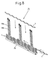
- Fig. 8 is an explanatory view showing an arranging method of the helical wire members according to the present invention.
-
- Hereinafter, embodiments of the present invention will be explained with reference to the drawings.
- Referring to Figs. 1 to 6, a
helical wire member 1 is made of various wire materials such as metal, plastic, ceramic (inclusive of glass), concrete, carbon fiber, and wood. The diameter of a helix is about twice the diameter of the wire member. Thewire material 1 is wound in predetermined lead and pitch in such a fashion that crests 1a of thehelical wire member 1 and itstroughs 1b have substantially a similar shape, or the troughs are positioned are in conformity with, or are outside from, the center of the helix. Owing to this winding structure, thehelical wire members 1 are wound so that a space at the helical center does not exist when viewed from the axial direction. - Incidentally, the
helical wire member 1 shown in Figs. 2 and 3 has a right-turn helical structure. However, the winding structure of the helix is not limited, and a left-turn helical structure may be used, as well. - A
panel body 3 using thehelical wire members 1 is constituted in the following way. - A
frame 5 of thepanel body 3 shown in Fig. 1 includes a pair of right andleft fixing frames fixing frame upper frame lower frame panel body 3 and oppose each other. A plurality offixing bars 11 having an axis thereof extending in a direction crossing the longitudinal direction of the upper andlower frames lower frames fixing frames 7 with gaps between them such that they can engage with thetroughs 1b of thehelical wire members 1 in the longitudinal direction. - As shown in Fig. 4, a plurality of
fixing bars 13 having an axis thereof extending in the direction crossing the longitudinal direction of the upper andlower frames lower frames other fixing frames 9 at the positions deviated by one trough 10 relative to thefixing bars 11 of thefixing frame 7, respectively. Incidentally, the deviation width between thefixing bar 11 and thefixing bar 13 is not particularly limited to the width of one trough 10 as described above, but may be set to a width corresponding to an arbitrary number of troughs. In a preferred embodiment, however,fixing bars helical wire member 1 with the deviation width of one trough. - As shown in Fig. 5, a large number of
helical wire members 1 having the axis thereof extending in the direction crossing the axis of thefixing bars 11 are arranged in close contact with one another on thefixing bars 11 of one of thefixing frames 7 in such a fashion that theircrests 1a and theirtroughs 1b mutually unite side by side. At this time, eachfixing bar 11 of the fixingframe 7 engages with thetrough 1b of eachhelical wire member 1 so arranged. - In the present invention, the
panel body 3 is assembled as theother fixing frame 9 is put on, and fixed to, one of thefixing frame 7 having a large number ofhelical wire members 1 arranged thereon as shown in Figs. 1 and 6. To fix thefixing frames upper frames lower frames screws 15, or may be bonded to one another. - The
panel body 3 so constituted is interconnected with one another in the following way and is used. Channel members having a connection recess formed on each side are used, and the end portion of anadjacent panel body 3 is fitted into the interconnection recess of the channel member, and is fastened by using a screw, whenever necessary. - Another interconnecting method is as follows. Every other wire member of a large number of
helical wire members 1 arranged on thepanel body 3, for example, are rotated so that the end portion of thehelical wire member 1 protrudes from one of the end portions of thepanel body 3 in a predetermined width. Accordingly, recesses corresponding to the protruding width are formed at the other end in every other of thehelical wire members 1. - The end portion of the protruding
helical wire member 1 is fitted into the recess at the other end of theadjacent panel body 3, and thecrest 1a andtrough 1b are united respectively with thecrest 1a andtrough 1b of the adjacenthelical wire member 1 to thereby interconnect thepanel bodies 3 with one another. - In this interconnecting method, one of the ends of a part of the
helical wire members 1 may be so arranged as to protrude by a predetermined width to the otherhelical wire members 1 to constitute thepanel body 3. - In the
panel body 3 according to this embodiment, thehelical wire member 1 itself has a diameter of the helix that is about twice the diameter of thehelical wire member 1. Therefore, in comparison with one sheet-like panel body, the panel can be constituted by about 1/2 of the materials, and the weight can be reduced. At a working site, thepanel body 3 can be assembled by arranging a large number ofhelical wire members 1 on one of thefixing frames 7 and then putting and fixing theother fixing frame 9. Therefore, transportation efficiency can be improved. - Although the
panel 3 can be constituted by 1/2 of the materials, the force acting on thepanel body 3 can be borne and dispersed by the helical slope of thecrests 1a of eachhelical wire member 1 and itstroughs 1b that unite with one another side by side. Therefore, thepanel 3 has high strength. - When a part of the
helical wire members 1 in thepanel body 3 is damaged, the damagedhelical wire member 1 is rotated and pulled out. Then, a newhelical wire member 1 is inserted among thehelical wire members 1 and is rotated so that thecrest 1a and thetrough 1b can be united with thecrest 1a and thetrough 1b of theadjacent wire member 1 side by side. In this way, repair can be done. - In the explanation given above, the
panel body 3 is constituted by arranging a large number ofhelical wire members 1 having the same winding direction (e.g. right-turn), and clamping and fixing them by thefixing bars troughs 1b on both surface sides. It is also possible to constitute apanel body 3 by arranging the left-turnhelical wire members 1 in the same way as described above. To interconnect a plurality of panel bodies, the right-turn helical panel bodies and the left-turn helical panel bodies may be alternately arranged and interconnected. In this case, the resulting product more strongly resists deformation in the diagonal direction and can restrict this deformation better than when the helical panel bodies having the same helical direction are used. A similar effect can also be obtained, for example, when the left-turn helical wire members are arranged in superposition on the right-turn helical wire members and clamping them by the fixing bars to constitute a multi-layered panel body. - Pairs of fixing
bars crest 1a or onetrough 1b of the helical wire member are implanted to aframe 73 of apanel body 71 with a suitable gap in the longitudinal direction as shown in Fig. 7. A large number ofhelical wire members 1 are arranged between each pair of fixingbars bar 75a engages with thetroughs 1b on the front side and the fixingbar 75b engages with thetroughs 1b on the back side. - The arranging method of each
helical wire member 1 to theframe 73 may be either the method that pushes eachhelical wire member 1 from above theframe 73 between each pair of fixingbars helical wire member 1 while the distal end portion is inserted from the side of theframe 73 between the fixingbars helical wire member 1 so that the fixing bars 75a and 75b engage with thetroughs 1b. - While a predetermined number of
helical wire members 1 are arranged between each pair of fixingbars frame 77 is fixed to the upper end portions of the fixing bars 75a and 75b to assemble thepanel body 71. Through-holes 77a are bored in the fixingframe 77 at positions corresponding to the fixing bars 75a and 75b, and screws are threaded at the upper end of the fixing bars 75a and 75b. After a necessary number ofhelical wire members 1 are arranged between the fixingbars frame 77 is fitted to the upper part of the fixing bars 75 and 75b and is fastened by screw engagement to form thepanel body 71. - This embodiment 2 is different from the
embodiment 1 in only the assembling method, and its function and effect is the same as that of theembodiment 1. The resulting panel body has high tenacity, high impact resistance and good assembly factor. - Incidentally, this embodiment can form the panel body comprising a curve surface by fixing a large number of
helical wire members 1 arranged by using the fixing bars curved into a predetermined shape. - The panel body using the helical wire members according to the present invention has excellent one-site assembly factor. It has high toughness and high impact resistance.
Claims (2)
- A panel body, using helical wire members, comprising:a large number of helical wire members obtained by helically winding, at a predetermined lead and pitch, wire materials having a predetermined outer diameter in such a fashion that a diameter of a helix is about twice the outer diameter of said wire materials, crests and troughs of said wire materials have substantially a similar shape and each of said troughs is positioned outside the center of the helix;a first fixing frame having first fixing bars fitted thereto, said first fixing bars being fitted with predetermined gaps to frame members opposing each other with a predetermined gap between them, and engaging with said troughs positioned on the side of one of the surfaces of said helical wire members; anda second fixing frame having second fixing bars fitted thereto, said second fixing bars being fitted with predetermined gaps to frame members fixed to said frame members of said first frame, engaging with said troughs on the other side surface side and fixing said large number of helical wire members.
- A panel body, using helical wire members, comprising:a large number of helical wire members obtained by helically winding, in a predetermined lead and pitch, wire materials having a predetermined outer diameter in such a fashion that a diameter of a helix is about twice the outer diameter of said wire materials, crests and troughs of said wire materials have substantially a similar shape and each of said troughs is positioned outside the center of the helix;support frames provided with a plurality of pairs of fixing bars with predetermined gaps in a longitudinal direction thereof, each pair of said fixing bars being fixed by support frame members on both sides of the axis of said helical wire members, and engaging with said troughs of said helical wire members arranged between said pair of fixing bars on the front side and the back side; andfixing members fixed to distal end portions of said fixing bars through which said helical wire members are arranged while said fixing bars engage with said troughs, and fastening each of said helical wire members.
Applications Claiming Priority (3)
| Application Number | Priority Date | Filing Date | Title |
|---|---|---|---|
| JP2000153989A JP4237377B2 (en) | 2000-05-25 | 2000-05-25 | Panel body using spiral wire |
| JP2000153989 | 2000-05-25 | ||
| PCT/JP2001/004229 WO2001090503A1 (en) | 2000-05-25 | 2001-05-21 | Panel body using spiral wire |
Publications (3)
| Publication Number | Publication Date |
|---|---|
| EP1284328A1 true EP1284328A1 (en) | 2003-02-19 |
| EP1284328A4 EP1284328A4 (en) | 2003-06-04 |
| EP1284328B1 EP1284328B1 (en) | 2005-02-02 |
Family
ID=18659152
Family Applications (1)
| Application Number | Title | Priority Date | Filing Date |
|---|---|---|---|
| EP01932168A Expired - Lifetime EP1284328B1 (en) | 2000-05-25 | 2001-05-21 | Panel body using spiral wire |
Country Status (8)
| Country | Link |
|---|---|
| US (1) | US6647694B2 (en) |
| EP (1) | EP1284328B1 (en) |
| JP (1) | JP4237377B2 (en) |
| KR (1) | KR100439708B1 (en) |
| CN (1) | CN1125220C (en) |
| DE (1) | DE60108743T2 (en) |
| TW (1) | TW473590B (en) |
| WO (1) | WO2001090503A1 (en) |
Families Citing this family (3)
| Publication number | Priority date | Publication date | Assignee | Title |
|---|---|---|---|---|
| JP4237377B2 (en) * | 2000-05-25 | 2009-03-11 | 暢彦 桂 | Panel body using spiral wire |
| US9038348B1 (en) * | 2013-12-18 | 2015-05-26 | General Electric Company | Lattice tower assembly for a wind turbine |
| CN107419841A (en) * | 2017-05-03 | 2017-12-01 | 北京建筑大学 | A kind of Concrete Sandwich Panel and preparation method thereof |
Family Cites Families (6)
| Publication number | Priority date | Publication date | Assignee | Title |
|---|---|---|---|---|
| DE58909543D1 (en) * | 1988-07-13 | 1996-02-08 | Kabelmetal Electro Gmbh | Elongated shaped strand |
| US5753355A (en) * | 1995-04-20 | 1998-05-19 | Nippon Laser & Electronics Lab. | Collective helical-elements structure |
| JP3280827B2 (en) | 1995-04-20 | 2002-05-13 | 暢彦 桂 | Spiral structure |
| JP3249030B2 (en) | 1995-04-20 | 2002-01-21 | 暢彦 桂 | Building components |
| JP3484295B2 (en) | 1996-05-24 | 2004-01-06 | 暢彦 桂 | Spiral structure |
| JP4237377B2 (en) * | 2000-05-25 | 2009-03-11 | 暢彦 桂 | Panel body using spiral wire |
-
2000
- 2000-05-25 JP JP2000153989A patent/JP4237377B2/en not_active Expired - Fee Related
-
2001
- 2001-05-21 DE DE60108743T patent/DE60108743T2/en not_active Expired - Lifetime
- 2001-05-21 KR KR10-2002-7000987A patent/KR100439708B1/en not_active Expired - Fee Related
- 2001-05-21 CN CN01801432A patent/CN1125220C/en not_active Expired - Fee Related
- 2001-05-21 EP EP01932168A patent/EP1284328B1/en not_active Expired - Lifetime
- 2001-05-21 US US10/048,365 patent/US6647694B2/en not_active Expired - Lifetime
- 2001-05-21 WO PCT/JP2001/004229 patent/WO2001090503A1/en not_active Ceased
- 2001-05-24 TW TW090112545A patent/TW473590B/en not_active IP Right Cessation
Non-Patent Citations (2)
| Title |
|---|
| No further relevant documents disclosed * |
| See also references of WO0190503A1 * |
Also Published As
| Publication number | Publication date |
|---|---|
| JP2001329652A (en) | 2001-11-30 |
| EP1284328A4 (en) | 2003-06-04 |
| US20020104284A1 (en) | 2002-08-08 |
| DE60108743D1 (en) | 2005-03-10 |
| WO2001090503A1 (en) | 2001-11-29 |
| TW473590B (en) | 2002-01-21 |
| KR100439708B1 (en) | 2004-07-12 |
| EP1284328B1 (en) | 2005-02-02 |
| DE60108743T2 (en) | 2006-03-30 |
| CN1125220C (en) | 2003-10-22 |
| KR20020045602A (en) | 2002-06-19 |
| JP4237377B2 (en) | 2009-03-11 |
| US6647694B2 (en) | 2003-11-18 |
| CN1380925A (en) | 2002-11-20 |
Similar Documents
| Publication | Publication Date | Title |
|---|---|---|
| CA2026397C (en) | Beam member for concrete forming system | |
| UA64747C2 (en) | Structural member (versions) and method ror its producing | |
| US5426822A (en) | Hinge structure | |
| CN1646776A (en) | Fiber architecture for a composite pole | |
| US6684912B2 (en) | Net body using helical wire members | |
| EP1284328B1 (en) | Panel body using spiral wire | |
| CN1650075A (en) | Space truss | |
| WO1988010343A1 (en) | Metal frame structure | |
| GB2288417A (en) | Elongate structural elements | |
| CA2445254C (en) | T-link of two profiled sections | |
| JP3249030B2 (en) | Building components | |
| US6634154B1 (en) | Plastic post | |
| WO2002008538A1 (en) | Metal roof truss | |
| US1166399A (en) | Iron structure. | |
| US5753355A (en) | Collective helical-elements structure | |
| EP1304418B1 (en) | Node for three-dimensional or treelike structures | |
| CN214614732U (en) | Novel prefabricated shear wall | |
| RU93055850A (en) | BUILDING PANEL | |
| RU2037034C1 (en) | Panel manufacturing method | |
| JP3828374B2 (en) | Fixing muscle | |
| JPH0921217A (en) | Spiral stairs and connecting fittings for spiral stairs | |
| KR0150274B1 (en) | Rebar mesh with multiple deformations | |
| SU1073400A1 (en) | Fastener for securing wooden parts | |
| SU1059096A1 (en) | Support unit of adhesive-bound wooden board column | |
| JPH10169006A (en) | Truss frame member and truss base structure using the same |
Legal Events
| Date | Code | Title | Description |
|---|---|---|---|
| PUAI | Public reference made under article 153(3) epc to a published international application that has entered the european phase |
Free format text: ORIGINAL CODE: 0009012 |
|
| 17P | Request for examination filed |
Effective date: 20020221 |
|
| AK | Designated contracting states |
Designated state(s): AT BE CH CY DE DK ES FI FR GB GR IE IT LI LU MC NL PT SE TR |
|
| A4 | Supplementary search report drawn up and despatched |
Effective date: 20030422 |
|
| GRAP | Despatch of communication of intention to grant a patent |
Free format text: ORIGINAL CODE: EPIDOSNIGR1 |
|
| GRAS | Grant fee paid |
Free format text: ORIGINAL CODE: EPIDOSNIGR3 |
|
| GRAA | (expected) grant |
Free format text: ORIGINAL CODE: 0009210 |
|
| AK | Designated contracting states |
Kind code of ref document: B1 Designated state(s): BE DE FR |
|
| REG | Reference to a national code |
Ref country code: IE Ref legal event code: FG4D |
|
| REF | Corresponds to: |
Ref document number: 60108743 Country of ref document: DE Date of ref document: 20050310 Kind code of ref document: P |
|
| PLBE | No opposition filed within time limit |
Free format text: ORIGINAL CODE: 0009261 |
|
| STAA | Information on the status of an ep patent application or granted ep patent |
Free format text: STATUS: NO OPPOSITION FILED WITHIN TIME LIMIT |
|
| ET | Fr: translation filed | ||
| 26N | No opposition filed |
Effective date: 20051103 |
|
| REG | Reference to a national code |
Ref country code: DE Ref legal event code: R082 Ref document number: 60108743 Country of ref document: DE Representative=s name: VOSSIUS & PARTNER, DE |
|
| REG | Reference to a national code |
Ref country code: DE Ref legal event code: R081 Ref document number: 60108743 Country of ref document: DE Owner name: TAIHEI MANUFACTURING CO., LTD., JP Free format text: FORMER OWNER: NIPPON STEEL CORP., TAIHEI MANUFACTURING CO., LTD.,NOBUHIKO KATSURA, , JP Effective date: 20130422 Ref country code: DE Ref legal event code: R081 Ref document number: 60108743 Country of ref document: DE Owner name: KATSURA, NOBUHIKO, JP Free format text: FORMER OWNER: NIPPON STEEL CORP., TAIHEI MANUFACTURING CO., LTD.,NOBUHIKO KATSURA, , JP Effective date: 20130422 Ref country code: DE Ref legal event code: R081 Ref document number: 60108743 Country of ref document: DE Owner name: NIPPON STEEL & SUMITOMO METAL CORPORATION, JP Free format text: FORMER OWNER: NIPPON STEEL CORP., TAIHEI MANUFACTURING CO., LTD.,NOBUHIKO KATSURA, , JP Effective date: 20130422 Ref country code: DE Ref legal event code: R082 Ref document number: 60108743 Country of ref document: DE Representative=s name: VOSSIUS & PARTNER, DE Effective date: 20130422 Ref country code: DE Ref legal event code: R082 Ref document number: 60108743 Country of ref document: DE Representative=s name: VOSSIUS & PARTNER PATENTANWAELTE RECHTSANWAELT, DE Effective date: 20130422 Ref country code: DE Ref legal event code: R081 Ref document number: 60108743 Country of ref document: DE Owner name: KATSURA, NOBUHIKO, OMURA, JP Free format text: FORMER OWNER: NIPPON STEEL CORP., TAIHEI MANUFACTURING CO., LTD.,NOBUHIKO KATSURA, , JP Effective date: 20130422 Ref country code: DE Ref legal event code: R081 Ref document number: 60108743 Country of ref document: DE Owner name: NIPPON STEEL & SUMITOMO METAL CORPORATION, JP Free format text: FORMER OWNERS: NIPPON STEEL CORP., TOKIO/TOKYO, JP; TAIHEI MANUFACTURING CO., LTD., OSAKA, JP; KATSURA, NOBUHIKO, OMURA, NAGASAKI, JP Effective date: 20130422 Ref country code: DE Ref legal event code: R081 Ref document number: 60108743 Country of ref document: DE Owner name: TAIHEI MANUFACTURING CO., LTD., JP Free format text: FORMER OWNERS: NIPPON STEEL CORP., TOKIO/TOKYO, JP; TAIHEI MANUFACTURING CO., LTD., OSAKA, JP; KATSURA, NOBUHIKO, OMURA, NAGASAKI, JP Effective date: 20130422 Ref country code: DE Ref legal event code: R081 Ref document number: 60108743 Country of ref document: DE Owner name: KATSURA, NOBUHIKO, OMURA, JP Free format text: FORMER OWNERS: NIPPON STEEL CORP., TOKIO/TOKYO, JP; TAIHEI MANUFACTURING CO., LTD., OSAKA, JP; KATSURA, NOBUHIKO, OMURA, NAGASAKI, JP Effective date: 20130422 |
|
| REG | Reference to a national code |
Ref country code: FR Ref legal event code: CA Effective date: 20130913 Ref country code: FR Ref legal event code: CD Owner name: NIPPON STEEL & SUMITOMO METAL CORPORATION, JP Effective date: 20130913 |
|
| REG | Reference to a national code |
Ref country code: FR Ref legal event code: PLFP Year of fee payment: 16 |
|
| REG | Reference to a national code |
Ref country code: FR Ref legal event code: PLFP Year of fee payment: 17 |
|
| PGFP | Annual fee paid to national office [announced via postgrant information from national office to epo] |
Ref country code: FR Payment date: 20170413 Year of fee payment: 17 Ref country code: DE Payment date: 20170516 Year of fee payment: 17 |
|
| PGFP | Annual fee paid to national office [announced via postgrant information from national office to epo] |
Ref country code: BE Payment date: 20170413 Year of fee payment: 17 |
|
| REG | Reference to a national code |
Ref country code: DE Ref legal event code: R119 Ref document number: 60108743 Country of ref document: DE |
|
| REG | Reference to a national code |
Ref country code: BE Ref legal event code: MM Effective date: 20180531 |
|
| PG25 | Lapsed in a contracting state [announced via postgrant information from national office to epo] |
Ref country code: FR Free format text: LAPSE BECAUSE OF NON-PAYMENT OF DUE FEES Effective date: 20180531 Ref country code: DE Free format text: LAPSE BECAUSE OF NON-PAYMENT OF DUE FEES Effective date: 20181201 |
|
| PG25 | Lapsed in a contracting state [announced via postgrant information from national office to epo] |
Ref country code: BE Free format text: LAPSE BECAUSE OF NON-PAYMENT OF DUE FEES Effective date: 20180531 |