EP1283925B1 - Arrangement for an attachment - Google Patents
Arrangement for an attachment Download PDFInfo
- Publication number
- EP1283925B1 EP1283925B1 EP01934712A EP01934712A EP1283925B1 EP 1283925 B1 EP1283925 B1 EP 1283925B1 EP 01934712 A EP01934712 A EP 01934712A EP 01934712 A EP01934712 A EP 01934712A EP 1283925 B1 EP1283925 B1 EP 1283925B1
- Authority
- EP
- European Patent Office
- Prior art keywords
- fastener
- bushes
- plates
- pins
- attachment
- Prior art date
- Legal status (The legal status is an assumption and is not a legal conclusion. Google has not performed a legal analysis and makes no representation as to the accuracy of the status listed.)
- Expired - Lifetime
Links
- 230000008878 coupling Effects 0.000 claims abstract 3
- 238000010168 coupling process Methods 0.000 claims abstract 3
- 238000005859 coupling reaction Methods 0.000 claims abstract 3
- 238000005259 measurement Methods 0.000 claims description 5
- 238000000034 method Methods 0.000 claims description 4
- 238000004873 anchoring Methods 0.000 claims 1
- 238000012986 modification Methods 0.000 description 2
- 230000004048 modification Effects 0.000 description 2
- 230000009286 beneficial effect Effects 0.000 description 1
- 210000000078 claw Anatomy 0.000 description 1
- 238000010276 construction Methods 0.000 description 1
- 230000002265 prevention Effects 0.000 description 1
Images

Classifications
-
- E—FIXED CONSTRUCTIONS
- E02—HYDRAULIC ENGINEERING; FOUNDATIONS; SOIL SHIFTING
- E02F—DREDGING; SOIL-SHIFTING
- E02F3/00—Dredgers; Soil-shifting machines
- E02F3/04—Dredgers; Soil-shifting machines mechanically-driven
- E02F3/28—Dredgers; Soil-shifting machines mechanically-driven with digging tools mounted on a dipper- or bucket-arm, i.e. there is either one arm or a pair of arms, e.g. dippers, buckets
- E02F3/36—Component parts
- E02F3/3604—Devices to connect tools to arms, booms or the like
- E02F3/3609—Devices to connect tools to arms, booms or the like of the quick acting type, e.g. controlled from the operator seat
- E02F3/3636—Devices to connect tools to arms, booms or the like of the quick acting type, e.g. controlled from the operator seat using two or four movable transversal pins
-
- Y—GENERAL TAGGING OF NEW TECHNOLOGICAL DEVELOPMENTS; GENERAL TAGGING OF CROSS-SECTIONAL TECHNOLOGIES SPANNING OVER SEVERAL SECTIONS OF THE IPC; TECHNICAL SUBJECTS COVERED BY FORMER USPC CROSS-REFERENCE ART COLLECTIONS [XRACs] AND DIGESTS
- Y10—TECHNICAL SUBJECTS COVERED BY FORMER USPC
- Y10T—TECHNICAL SUBJECTS COVERED BY FORMER US CLASSIFICATION
- Y10T403/00—Joints and connections
- Y10T403/59—Manually releaseable latch type
Definitions
- the present invention rebates to an arrangement pertaining to an implement attachment as defined in the preamble of claim 1.
- the present invention also relates to a method as defined in the preamble of claim 4.
- Various types of machine tools such as excavators, for example, include an arm to which different implements/tools can be connected.
- the arm thus includes means for connection with the implement attachment.
- a typical fastener system used in respect of the working arm/shaft/dipper stick of an excavator, digger or corresponding machine resides in the provision of two mutually parallel fastener pins at the tip of said arm, these pins engaging the implement attachment.
- different makes of such machines have different measurements and distances with respect to said fastener pins, therewith requiring the implement attachment to be especially designed for different machine sizes and machine makes.
- this presents a problem with respect to the stocking and the delivery of both the implement attachments and the implements, tools, or mounting systems carried thereby.
- An object of the present invention is to provide an extremely simple and attractive arrangement so that the implement attachment can be readily adapted to the measurements and geometric variations of sleaver and pins with which the aforesaid problems can be solved.
- This object is achieved with an inventive arrangement and inventive method having the characteristic features set forth in the accompanying Claims.
- FIG. 1 is a perspective illustration of a working arm in the form of a digger shaft that carries an inventive implement/tool attachment
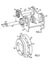
- Fig. 2 is a partially exploded perspective view, showing the implement attachment loosened from the shaft
- Fig. 3 is an enlarged perspective view of a bushing.
- Fig. 1 illustrates a typical working arm 10 of an excavator, digger or corresponding machine.
- the arm 10 which is also known as the machine shaft or dipper stick, carries an inventive implement attachment 30.
- the arm 10 is shown to carry a fastener sleeve 11 at its lower end.
- the arm 10 carries a pair of linkage arms 12 which, in turn, carry a lower linkage arm 13.
- a fastener sleeve 14 is carried at the free end of the linkage arm 13.
- the working movement of the linkage arms 12 and 13 is effected by a manoeuvring device in the form of an hydraulic cylinder 15.
- the implement attachment 30 is coupled to the arm 10 by means of two fastener pins 16,17 that extend through the sleeves 11 and 14. Different makes of machine have different positioning of the fastener sleeves 11,14 and their associated fastener pins 16,17, and also vary with respect to sleeve and pin measurements.
- the inventive implement attachment 30 is designed so that it can be readily adapted to the measurements and geometric variations of the sleeves 11,14 and the pins 16,17.
- the implement attachment 30 can, of course, carry all conceivable types of implement/tools, such as rotators, buckets, shovels, hydraulic hammers, gripping claws, etc.
- the implement attachment 30 may also carry a quick-fastener or some similar mounting system designed for the implement concerned. Although no implement is shown in the figures, it will be understood that the bottom part 31 of the attachment 30 can be adapted to the implement in question.
- the attachment 30 includes two side-plates 32,33 which support an implement/tool (not shown), either directly or indirectly.
- the side-plate 32 includes two circular holes 34,35, and the side-plate 33 includes two circular holes 36,37.
- the diameters of the holes 34-37 are much larger than the diameters of respective pins 16,17, so as to enable inventive bushes 44-47 to be mounted in said holes.
- the bushes 44-47 include a circular flange 50 that has an inner surface 51 which lies against the inside of the side-plates 32,33, and a circular guide portion 52 which fits snugly in the circular holes 34-37, i.e. in the absence of play.
- the circular guide portion 52 is provided with an entry portion 53 of slightly smaller diameter than its remaining part.
- the flanges 50 include a plurality of screw-threaded blind holes 55, and the side-plates 32,33 include corresponding holes 38, so as to enable the bushes 44-47 to be anchored to the side-plates 32,33 by means of screws 70, as shown in Figs. 1 and 2 . It is possible to substitute one or more of the screws 70 for guide pins, provided that the holes in the side-plates 32,33 and in the flanges 50 are adapted to this end.
- the bushes 44-47 are adapted to the fastener sleeves 11,14 and the fastener pins 16,17 concerned, by providing holes 56 for the fastener pins 16,17 through the bushes, these holes most often being positioned excentrically in relation to the centre line of the circular guide portion 52.
- the circular guide portion 52 has been given a diameter which can accommodate variations in the fastener-pin hole patterns from the machine manufacturers to be covered.
- the thickness of the flanges of respective bushes 44-47 is adapted to the lengths of respective fastener sleeves concerned, so that the clearances between the fastener sleeves 11,14 and the outer end plane 57 of respective flanges 50 will be a minimum.
- One end of the illustrated fastener pins 16,17 carries a perforated shoulder 18, wherewith the pins can be secured in their position of use by screwing said pins into the outer end surface 58 of the bush in question, said end surface including a screw-threaded hole 59 for receiving a screw fastener 71.
- the bushes 44-47 can be easily adapted to enable the use of other commercially-available fastener pins, without needing to modify said pins.
- the inventive implement attachment enables a common attachment including relevant implement and/or accessory, to be finally adapted to comply with customer requirements in conjunction with delivery, by screwing the bushes concerned firmly to the implement attachment.
- This provides significant advantages with respect to stock holding and delivery times. It is also possible to subsequently change the implement attachment by simply exchanging the bushes, therewith enabling the attachment to be fitted to excavating machines, digging machines, etc., of other manufactures.
- the invention thus provides a highly rewarding flexibility.
- the outer cylindrical shape of the guide portion of the respective bushes enables play-free connection with corresponding holes in the side-plates, this facility being highly significant from the life expectancy of the bush.
- the outer contour of the flange may deviate from the illustrate cylindrical contour if so desired, for instance when necessary because of space problems.
Landscapes
- Engineering & Computer Science (AREA)
- Mechanical Engineering (AREA)
- Mining & Mineral Resources (AREA)
- Civil Engineering (AREA)
- General Engineering & Computer Science (AREA)
- Structural Engineering (AREA)
- Pivots And Pivotal Connections (AREA)
- Agricultural Machines (AREA)
- Shovels (AREA)
- Mechanical Operated Clutches (AREA)
- Arrangement And Mounting Of Devices That Control Transmission Of Motive Force (AREA)
- Supplying Of Containers To The Packaging Station (AREA)
- Outer Garments And Coats (AREA)
- Load-Engaging Elements For Cranes (AREA)
Abstract
Description
- The present invention rebates to an arrangement pertaining to an implement attachment as defined in the preamble of claim 1. The present invention also relates to a method as defined in the preamble of claim 4.
- Various types of machine tools, such as excavators, for example, include an arm to which different implements/tools can be connected. The arm thus includes means for connection with the implement attachment. A typical fastener system used in respect of the working arm/shaft/dipper stick of an excavator, digger or corresponding machine resides in the provision of two mutually parallel fastener pins at the tip of said arm, these pins engaging the implement attachment. However, different makes of such machines have different measurements and distances with respect to said fastener pins, therewith requiring the implement attachment to be especially designed for different machine sizes and machine makes. Among other things, this presents a problem with respect to the stocking and the delivery of both the implement attachments and the implements, tools, or mounting systems carried thereby.
- The above-mentioned problems are described in
US 5,927,665 , an which the preamble of claim 1 is based This US patent specification proposes the use of adapter plugs or bushes of relatively complicated outer contours, said bushes being held in place by means of screws that pass transversely through the bushes and fastener pins. The fastener pins must therefore be designed especially. The adapter plugs are expensive to produce because of a complex construction, and the side-plate cut-outs or recesses required for the adapter plugs are also complicated and expensive. It is also difficult to achieve a close fit. - An object of the present invention is to provide an extremely simple and attractive arrangement so that the implement attachment can be readily adapted to the measurements and geometric variations of sleaver and pins with which the aforesaid problems can be solved. This object is achieved with an inventive arrangement and inventive method having the characteristic features set forth in the accompanying Claims.
- Of the many advantages afforded by the present invention it can be mentioned that the design of the bushes is highly beneficial from a total working aspect. Prevention of rotation of the bushes and fixation of said bushes relative to the side plates is achieved with simple means. Another advantage afforded by the inventive arrangement is that the fastener pins provided by the machine manufacturers can usually be used without requiring modification. The invention also affords both technical and economical advantages.
- The invention will now be described by way of example and also with reference to the accompanying drawings, in which
Fig. 1 is a perspective illustration of a working arm in the form of a digger shaft that carries an inventive implement/tool attachment;Fig. 2 is a partially exploded perspective view, showing the implement attachment loosened from the shaft; andFig. 3 is an enlarged perspective view of a bushing. -
Fig. 1 illustrates a typical working arm 10 of an excavator, digger or corresponding machine. The arm 10, which is also known as the machine shaft or dipper stick, carries aninventive implement attachment 30. The arm 10 is shown to carry a fastener sleeve 11 at its lower end. The arm 10 carries a pair oflinkage arms 12 which, in turn, carry alower linkage arm 13. Afastener sleeve 14 is carried at the free end of thelinkage arm 13. The working movement of thelinkage arms hydraulic cylinder 15. Theimplement attachment 30 is coupled to the arm 10 by means of twofastener pins 16,17 that extend through thesleeves 11 and 14. Different makes of machine have different positioning of thefastener sleeves 11,14 and their associatedfastener pins 16,17, and also vary with respect to sleeve and pin measurements. - The
inventive implement attachment 30 is designed so that it can be readily adapted to the measurements and geometric variations of thesleeves 11,14 and thepins 16,17. - The
implement attachment 30 can, of course, carry all conceivable types of implement/tools, such as rotators, buckets, shovels, hydraulic hammers, gripping claws, etc. Theimplement attachment 30 may also carry a quick-fastener or some similar mounting system designed for the implement concerned. Although no implement is shown in the figures, it will be understood that thebottom part 31 of theattachment 30 can be adapted to the implement in question. - The
attachment 30 includes two side-plates plate 32 includes twocircular holes plate 33 includes twocircular holes respective pins 16,17, so as to enable inventive bushes 44-47 to be mounted in said holes. - The bushes 44-47 include a
circular flange 50 that has an inner surface 51 which lies against the inside of the side-plates circular guide portion 52 which fits snugly in the circular holes 34-37, i.e. in the absence of play. In order to facilitate fitting of the bushes 44-47 in respective holes 34-37, thecircular guide portion 52 is provided with anentry portion 53 of slightly smaller diameter than its remaining part. Theflanges 50 include a plurality of screw-threadedblind holes 55, and the side-plates corresponding holes 38, so as to enable the bushes 44-47 to be anchored to the side-plates screws 70, as shown inFigs. 1 and2 . It is possible to substitute one or more of thescrews 70 for guide pins, provided that the holes in the side-plates flanges 50 are adapted to this end. - In accordance with the invention, the bushes 44-47 are adapted to the
fastener sleeves 11,14 and thefastener pins 16,17 concerned, by providing holes 56 for thefastener pins 16,17 through the bushes, these holes most often being positioned excentrically in relation to the centre line of thecircular guide portion 52. Thecircular guide portion 52 has been given a diameter which can accommodate variations in the fastener-pin hole patterns from the machine manufacturers to be covered. The thickness of the flanges of respective bushes 44-47 is adapted to the lengths of respective fastener sleeves concerned, so that the clearances between thefastener sleeves 11,14 and theouter end plane 57 ofrespective flanges 50 will be a minimum. - One end of the illustrated
fastener pins 16,17 carries aperforated shoulder 18, wherewith the pins can be secured in their position of use by screwing said pins into theouter end surface 58 of the bush in question, said end surface including a screw-threadedhole 59 for receiving a screw fastener 71. It will be readily seen that the bushes 44-47 can be easily adapted to enable the use of other commercially-available fastener pins, without needing to modify said pins. - Thus, the inventive implement attachment enables a common attachment including relevant implement and/or accessory, to be finally adapted to comply with customer requirements in conjunction with delivery, by screwing the bushes concerned firmly to the implement attachment. This provides significant advantages with respect to stock holding and delivery times. It is also possible to subsequently change the implement attachment by simply exchanging the bushes, therewith enabling the attachment to be fitted to excavating machines, digging machines, etc., of other manufactures. The invention thus provides a highly rewarding flexibility.
- It will also be noted that the outer cylindrical shape of the guide portion of the respective bushes enables play-free connection with corresponding holes in the side-plates, this facility being highly significant from the life expectancy of the bush. However, the outer contour of the flange may deviate from the illustrate cylindrical contour if so desired, for instance when necessary because of space problems.
- It will be understood that the detail design of the side-plates may be varied within the scope of the invention, and also their connection to relevant implements or mounting systems. The invention is therefore not restricted to the illustrated and described embodiment, since changes and modifications are, of course, possible within the scope of the accompanying Claims.
Claims (5)
- An arrangement for coupling an implement attachment (30) to a working arm (10) of a working machine, wherein the arm (10) is connected to the implement attachment (30) through the medium of fastener sleeves (11,14) and fastener pins (16,17),
wherein the implement attachment (30) includes two side-plates (32,33) which each carry two bushes (44-47) that have holes (56) for receiving the fastener pins (16,17), all the bushes (44-47) include a circular guide portion (52) adapted to fit in a circular hole (34-37) in the side-plates (32,33);
said bushes -(44-47) include a flange (50) which is connected to the side-plates (32,33) by means of a fastener element (70) which extends through respective side-plates and is anchored to said flange of respective bushes;
said holes (56) for the fastener pins (16,17) are positioned eccentrically in relation to said circular guide portion (52) in respect of at least two of said bushes (45-47); and characterized in that an outer end surface (58) of two of said bushes (44,45) includes a screw-threaded hole (59) for receiving a screw fastener (71) where with the pins (18,17) can be secured in their position of use by screwing said screw fastened into the outer end surface (58) of the bush in question. - An arrangement according to Claim 1 characterized in that the thickness of the flanges (50) is adapted so that the flanges will essentially fill-out the distance between the side-plates (32,33) and the end parts of the fastener sleeves (11,14).
- An arrangement according to any one of Claims 1-2, characterized in that the side-plates (32,33) are connected to an implement, tool, or mounting system.
- A method of coupling an implement attachment (30) to a working arm (10) of a working machine, wherein the arm (10) is connected to the implement attachment (30) through the medium of fastener sleeves (11,14) and fastener pins (16,17), wherein the implement attachment (30) includes two side-plates (32,33) which each carry two bushes (44-47) that include holes (56) for receiving said fastener pins (16,17), solely using bushes (44-47)that include a flange (50) and a circular guide portion (52) which fits into a circular hole (34-37) in the side-plates (32,33);
connecting said flange to the side-plates (32,33) by means of a fastener element (70) which extends through respective side-plates;
anchoring said fastener element (70) to said flange (50) of respective bushes;
using different placements of the fastener pin hole (56) in respective bushings (44-47), so as to enable the attachment to be adapted to varying fastener pin positions; and
securing each of the fastener pins (16, 17) by in their position of use by means of a screw fastener (71) which is received by a screw-threaded hole (59) disposed in an outer end surface (58) of two of said bushes. - A method according to Claim 4, characterized by adapting the attachment to varying length measurements of the fastener sleeves (11,14), by varying the thicknesses of flanges (50) provided on respective bushes (44-47).
Applications Claiming Priority (3)
| Application Number | Priority Date | Filing Date | Title |
|---|---|---|---|
| SE0001651A SE0001651D0 (en) | 2000-05-04 | 2000-05-04 | Ways to attach a tool and attach it |
| SE0001651 | 2000-05-04 | ||
| PCT/SE2001/000978 WO2001083894A1 (en) | 2000-05-04 | 2001-05-04 | Arrangement for an attachment |
Publications (2)
| Publication Number | Publication Date |
|---|---|
| EP1283925A1 EP1283925A1 (en) | 2003-02-19 |
| EP1283925B1 true EP1283925B1 (en) | 2009-12-23 |
Family
ID=20279550
Family Applications (1)
| Application Number | Title | Priority Date | Filing Date |
|---|---|---|---|
| EP01934712A Expired - Lifetime EP1283925B1 (en) | 2000-05-04 | 2001-05-04 | Arrangement for an attachment |
Country Status (7)
| Country | Link |
|---|---|
| US (1) | US7204656B2 (en) |
| EP (1) | EP1283925B1 (en) |
| AT (1) | ATE453020T1 (en) |
| AU (1) | AU2001260868A1 (en) |
| DE (1) | DE60140866D1 (en) |
| SE (1) | SE0001651D0 (en) |
| WO (1) | WO2001083894A1 (en) |
Families Citing this family (26)
| Publication number | Priority date | Publication date | Assignee | Title |
|---|---|---|---|---|
| US6662681B2 (en) | 2002-01-14 | 2003-12-16 | Kent Demolition, Inc. | Connector assembly for mounting an implement to a prime mover |
| WO2003069077A1 (en) * | 2002-01-14 | 2003-08-21 | Kent Demolition, Inc. | Connector assembly for mounting an implement to a prime mover |
| FR2886953B1 (en) * | 2005-06-14 | 2009-02-06 | Morin Soc Par Actions Simplifi | JOINT SUPPORT FOR WORK EQUIPMENT TOOLS, CONSTITUTING A QUICK ATTACHMENT OR PART OF THE TOOL AND METHOD FOR MANUFACTURING THE SAME |
| US7770311B2 (en) | 2005-12-20 | 2010-08-10 | Craig Arthur Hahnel | Mounting system for excavation buckets and implements |
| US7966754B2 (en) * | 2006-03-02 | 2011-06-28 | Caterpillar Inc. | Adapter for attaching a tool to a machine |
| US7810260B2 (en) | 2007-12-21 | 2010-10-12 | Caterpillar Trimble Control Technologies Llc | Control system for tool coupling |
| WO2009102223A1 (en) * | 2008-02-13 | 2009-08-20 | Jb Attachments Limited | Versatile couplers |
| GB2466017B (en) * | 2008-12-08 | 2012-10-17 | Jcb Compact Products Ltd | Mounting assembly |
| WO2010124326A1 (en) * | 2009-04-28 | 2010-11-04 | Satera Engineering Pty Ltd | Bucket attachment |
| US20120227246A1 (en) * | 2009-07-09 | 2012-09-13 | Dawson Francis J | Apparatus for connection of an implement to machinery |
| DK177778B1 (en) * | 2010-05-31 | 2014-06-30 | Subcpartner As | Flexible articulated crane arm and method of loading and / or unloading an object using such crane arm |
| IT1403865B1 (en) * | 2011-02-17 | 2013-11-08 | Cambria | UNIVERSAL BRACKET FOR OPERATING ORGANS APPLICABLE TO EARTH HANDLING MACHINES |
| WO2012129139A1 (en) * | 2011-03-18 | 2012-09-27 | Paladin Brands Group, Inc. | Loader coupler with removable mount pins |
| US20130149023A1 (en) * | 2011-12-09 | 2013-06-13 | United Technologies Corporation | Adjustable clevis assembly |
| FI20125972A7 (en) * | 2012-09-20 | 2014-03-21 | R´N D Universal Oy | Adapter |
| FR3027037B1 (en) * | 2014-10-13 | 2018-01-26 | Groupe Mecalac | TOOL HOLDER FOR CONSTRUCTION OR PUBLIC WORKS EQUIPMENT |
| AU2016101243B4 (en) * | 2015-03-02 | 2017-02-23 | Statewide Building Group Pty Ltd | Coupling assembly |
| AU2015100239B4 (en) * | 2015-03-02 | 2017-02-02 | Statewide Building Group Pty Ltd | Adjustable ears, pickups and pins for excavator and excavating buckets and attachments |
| AU2016206213B2 (en) * | 2016-04-20 | 2022-11-10 | Statewide Building Group Pty Ltd | Coupling assembly |
| GB2550458A (en) * | 2016-05-18 | 2017-11-22 | Trufab Farm Machinery Pty Ltd | A tool attachment |
| EP3296198B1 (en) | 2016-09-15 | 2018-11-14 | AIRBUS HELICOPTERS DEUTSCHLAND GmbH | Adjustment of track and balance of a multi-blade rotor |
| US10385535B2 (en) * | 2016-11-11 | 2019-08-20 | Caterpillar Inc. | Bracket assembly for linkage assemblies of machines |
| US10801178B2 (en) | 2018-12-07 | 2020-10-13 | Deere & Company | Work tool attachment for a work machine |
| US10760243B2 (en) | 2018-12-07 | 2020-09-01 | Deere & Company | Work tool attachment for a work machine |
| DE102020105460A1 (en) * | 2020-03-02 | 2021-09-02 | OilQuick Deutschland KG | Quick coupler |
| US12467222B2 (en) | 2022-09-28 | 2025-11-11 | Attach Acquisition Holdco LLC | Universal mounting structure for excavator attachments |
Family Cites Families (9)
| Publication number | Priority date | Publication date | Assignee | Title |
|---|---|---|---|---|
| US4207693A (en) * | 1976-08-18 | 1980-06-17 | Hemphill Charles W | Backhoe bucket adapter bushing and pin method and apparatus |
| US4133121A (en) * | 1976-08-18 | 1979-01-09 | Hemphill Charles W | Backhoe bucket adapter bushing and pin method and apparatus |
| US4214840A (en) * | 1979-01-18 | 1980-07-29 | J. H. Beales Steel Fabricators, Ltd. | Quick-release coupler |
| JPS5846691U (en) * | 1981-09-24 | 1983-03-29 | 株式会社シマノ | bicycle crank |
| US4813163A (en) * | 1988-01-26 | 1989-03-21 | Construction Technology, Inc. | Alignment fitting for attaching implements to a backhoe |
| US4890974A (en) * | 1989-02-06 | 1990-01-02 | David Kistner | Easy connection of dipper stick to tool of an earth working machine |
| US5927665A (en) | 1998-07-02 | 1999-07-27 | Allied Construction Products, Inc. | Implement mounting system |
| US6158917A (en) * | 1999-02-23 | 2000-12-12 | Wolin; Robert H. | Retention mechanism for mounting pins |
| US6662681B2 (en) * | 2002-01-14 | 2003-12-16 | Kent Demolition, Inc. | Connector assembly for mounting an implement to a prime mover |
-
2000
- 2000-05-04 SE SE0001651A patent/SE0001651D0/en unknown
-
2001
- 2001-05-04 EP EP01934712A patent/EP1283925B1/en not_active Expired - Lifetime
- 2001-05-04 AU AU2001260868A patent/AU2001260868A1/en not_active Abandoned
- 2001-05-04 US US10/275,192 patent/US7204656B2/en not_active Expired - Lifetime
- 2001-05-04 WO PCT/SE2001/000978 patent/WO2001083894A1/en not_active Ceased
- 2001-05-04 AT AT01934712T patent/ATE453020T1/en not_active IP Right Cessation
- 2001-05-04 DE DE60140866T patent/DE60140866D1/en not_active Expired - Lifetime
Also Published As
| Publication number | Publication date |
|---|---|
| ATE453020T1 (en) | 2010-01-15 |
| EP1283925A1 (en) | 2003-02-19 |
| SE0001651D0 (en) | 2000-05-04 |
| AU2001260868A1 (en) | 2001-11-12 |
| WO2001083894A1 (en) | 2001-11-08 |
| US20030103804A1 (en) | 2003-06-05 |
| DE60140866D1 (en) | 2010-02-04 |
| US7204656B2 (en) | 2007-04-17 |
Similar Documents
| Publication | Publication Date | Title |
|---|---|---|
| US20030103804A1 (en) | Arrangement for an attachment | |
| US6938514B1 (en) | Connector assembly for mounting an implement to a prime mover | |
| US6364561B1 (en) | Connector system for earth working machines | |
| US5927665A (en) | Implement mounting system | |
| US6108951A (en) | Work machine having improved implement coupling arrangement | |
| US4813163A (en) | Alignment fitting for attaching implements to a backhoe | |
| US6233852B1 (en) | Universal coupler for excavator buckets | |
| EP2419570B1 (en) | Apparatus for connection of an implement to machinery | |
| US6857842B2 (en) | Adapter assembly for an implement coupling system | |
| FI3875692T3 (en) | Quick change device for a construction machine | |
| US10161102B2 (en) | Excavator attachments alignment tool | |
| CA2295894C (en) | Implement mounting system | |
| CA2468966C (en) | Connector assembly for mounting an implement to a prime mover | |
| EP1533426B1 (en) | Blade device | |
| KR19990088296A (en) | Arm with simplified attachment removable unit for construction equipment | |
| US20060254096A1 (en) | Quick attach coupling device | |
| KR100499103B1 (en) | Work attachment attachment device | |
| AU2004201141B2 (en) | Excavator tools | |
| US12601151B2 (en) | Universal hydraulic connecting quick coupler system | |
| KR200362690Y1 (en) | Tooth point of bucket for excavator | |
| JPH09287163A (en) | Hydraulic excavator working machine | |
| GB2337505A (en) | Apparatus for attaching an implement assembly to a stick of a work machine | |
| PT1896663E (en) | Articulating support for construction machine constituting a quick-release fastener and related manufacturing method | |
| JPH06128980A (en) | Attachment for construction equipment | |
| JP3605753B2 (en) | Quick coupler device for work machines |
Legal Events
| Date | Code | Title | Description |
|---|---|---|---|
| PUAI | Public reference made under article 153(3) epc to a published international application that has entered the european phase |
Free format text: ORIGINAL CODE: 0009012 |
|
| 17P | Request for examination filed |
Effective date: 20021204 |
|
| AK | Designated contracting states |
Designated state(s): AT BE CH CY DE DK ES FI FR GB GR IE IT LI LU MC NL PT SE TR |
|
| AX | Request for extension of the european patent |
Extension state: AL LT LV MK RO SI |
|
| 17Q | First examination report despatched |
Effective date: 20070806 |
|
| GRAP | Despatch of communication of intention to grant a patent |
Free format text: ORIGINAL CODE: EPIDOSNIGR1 |
|
| RIC1 | Information provided on ipc code assigned before grant |
Ipc: E02F 3/36 20060101AFI20090511BHEP |
|
| GRAS | Grant fee paid |
Free format text: ORIGINAL CODE: EPIDOSNIGR3 |
|
| GRAA | (expected) grant |
Free format text: ORIGINAL CODE: 0009210 |
|
| AK | Designated contracting states |
Kind code of ref document: B1 Designated state(s): AT BE CH CY DE DK ES FI FR GB GR IE IT LI LU MC NL PT SE TR |
|
| AX | Request for extension of the european patent |
Extension state: LT |
|
| REG | Reference to a national code |
Ref country code: GB Ref legal event code: FG4D |
|
| REG | Reference to a national code |
Ref country code: CH Ref legal event code: EP |
|
| REG | Reference to a national code |
Ref country code: IE Ref legal event code: FG4D |
|
| REF | Corresponds to: |
Ref document number: 60140866 Country of ref document: DE Date of ref document: 20100204 Kind code of ref document: P |
|
| REG | Reference to a national code |
Ref country code: SE Ref legal event code: TRGR |
|
| REG | Reference to a national code |
Ref country code: NL Ref legal event code: T3 |
|
| LTIE | Lt: invalidation of european patent or patent extension |
Effective date: 20091223 |
|
| PG25 | Lapsed in a contracting state [announced via postgrant information from national office to epo] |
Ref country code: AT Free format text: LAPSE BECAUSE OF FAILURE TO SUBMIT A TRANSLATION OF THE DESCRIPTION OR TO PAY THE FEE WITHIN THE PRESCRIBED TIME-LIMIT Effective date: 20091223 |
|
| PG25 | Lapsed in a contracting state [announced via postgrant information from national office to epo] |
Ref country code: ES Free format text: LAPSE BECAUSE OF FAILURE TO SUBMIT A TRANSLATION OF THE DESCRIPTION OR TO PAY THE FEE WITHIN THE PRESCRIBED TIME-LIMIT Effective date: 20100403 Ref country code: PT Free format text: LAPSE BECAUSE OF FAILURE TO SUBMIT A TRANSLATION OF THE DESCRIPTION OR TO PAY THE FEE WITHIN THE PRESCRIBED TIME-LIMIT Effective date: 20100423 |
|
| PG25 | Lapsed in a contracting state [announced via postgrant information from national office to epo] |
Ref country code: BE Free format text: LAPSE BECAUSE OF FAILURE TO SUBMIT A TRANSLATION OF THE DESCRIPTION OR TO PAY THE FEE WITHIN THE PRESCRIBED TIME-LIMIT Effective date: 20091223 |
|
| PG25 | Lapsed in a contracting state [announced via postgrant information from national office to epo] |
Ref country code: CY Free format text: LAPSE BECAUSE OF FAILURE TO SUBMIT A TRANSLATION OF THE DESCRIPTION OR TO PAY THE FEE WITHIN THE PRESCRIBED TIME-LIMIT Effective date: 20091223 Ref country code: GR Free format text: LAPSE BECAUSE OF FAILURE TO SUBMIT A TRANSLATION OF THE DESCRIPTION OR TO PAY THE FEE WITHIN THE PRESCRIBED TIME-LIMIT Effective date: 20100324 |
|
| PLBE | No opposition filed within time limit |
Free format text: ORIGINAL CODE: 0009261 |
|
| STAA | Information on the status of an ep patent application or granted ep patent |
Free format text: STATUS: NO OPPOSITION FILED WITHIN TIME LIMIT |
|
| 26N | No opposition filed |
Effective date: 20100924 |
|
| PG25 | Lapsed in a contracting state [announced via postgrant information from national office to epo] |
Ref country code: MC Free format text: LAPSE BECAUSE OF NON-PAYMENT OF DUE FEES Effective date: 20100531 |
|
| REG | Reference to a national code |
Ref country code: CH Ref legal event code: PL |
|
| GBPC | Gb: european patent ceased through non-payment of renewal fee |
Effective date: 20100504 |
|
| PG25 | Lapsed in a contracting state [announced via postgrant information from national office to epo] |
Ref country code: DK Free format text: LAPSE BECAUSE OF FAILURE TO SUBMIT A TRANSLATION OF THE DESCRIPTION OR TO PAY THE FEE WITHIN THE PRESCRIBED TIME-LIMIT Effective date: 20091223 |
|
| PG25 | Lapsed in a contracting state [announced via postgrant information from national office to epo] |
Ref country code: CH Free format text: LAPSE BECAUSE OF NON-PAYMENT OF DUE FEES Effective date: 20100531 Ref country code: LI Free format text: LAPSE BECAUSE OF NON-PAYMENT OF DUE FEES Effective date: 20100531 |
|
| PG25 | Lapsed in a contracting state [announced via postgrant information from national office to epo] |
Ref country code: IT Free format text: LAPSE BECAUSE OF FAILURE TO SUBMIT A TRANSLATION OF THE DESCRIPTION OR TO PAY THE FEE WITHIN THE PRESCRIBED TIME-LIMIT Effective date: 20091223 |
|
| PG25 | Lapsed in a contracting state [announced via postgrant information from national office to epo] |
Ref country code: IE Free format text: LAPSE BECAUSE OF NON-PAYMENT OF DUE FEES Effective date: 20100504 |
|
| PG25 | Lapsed in a contracting state [announced via postgrant information from national office to epo] |
Ref country code: GB Free format text: LAPSE BECAUSE OF NON-PAYMENT OF DUE FEES Effective date: 20100504 |
|
| PG25 | Lapsed in a contracting state [announced via postgrant information from national office to epo] |
Ref country code: LU Free format text: LAPSE BECAUSE OF NON-PAYMENT OF DUE FEES Effective date: 20100504 |
|
| PG25 | Lapsed in a contracting state [announced via postgrant information from national office to epo] |
Ref country code: TR Free format text: LAPSE BECAUSE OF FAILURE TO SUBMIT A TRANSLATION OF THE DESCRIPTION OR TO PAY THE FEE WITHIN THE PRESCRIBED TIME-LIMIT Effective date: 20091223 |
|
| REG | Reference to a national code |
Ref country code: DE Ref legal event code: R082 Ref document number: 60140866 Country of ref document: DE Representative=s name: MITSCHERLICH, PATENT- UND RECHTSANWAELTE, PART, DE |
|
| REG | Reference to a national code |
Ref country code: DE Ref legal event code: R082 Ref document number: 60140866 Country of ref document: DE Representative=s name: MITSCHERLICH, PATENT- UND RECHTSANWAELTE, PART, DE Effective date: 20140314 Ref country code: DE Ref legal event code: R081 Ref document number: 60140866 Country of ref document: DE Owner name: INDEXATOR GROUP AB, SE Free format text: FORMER OWNER: INDEXATOR AB, VINDELN, SE Effective date: 20140314 Ref country code: DE Ref legal event code: R081 Ref document number: 60140866 Country of ref document: DE Owner name: ROTOTILT GROUP AB, SE Free format text: FORMER OWNER: INDEXATOR AB, VINDELN, SE Effective date: 20140314 Ref country code: DE Ref legal event code: R082 Ref document number: 60140866 Country of ref document: DE Representative=s name: MITSCHERLICH, PATENT- UND RECHTSANWAELTE PARTM, DE Effective date: 20140314 |
|
| REG | Reference to a national code |
Ref country code: DE Ref legal event code: R082 Ref document number: 60140866 Country of ref document: DE Representative=s name: MITSCHERLICH, PATENT- UND RECHTSANWAELTE PARTM, DE |
|
| REG | Reference to a national code |
Ref country code: DE Ref legal event code: R081 Ref document number: 60140866 Country of ref document: DE Owner name: ROTOTILT GROUP AB, SE Free format text: FORMER OWNER: INDEXATOR GROUP AB, VINDELN, SE Effective date: 20150324 Ref country code: DE Ref legal event code: R082 Ref document number: 60140866 Country of ref document: DE Representative=s name: MITSCHERLICH, PATENT- UND RECHTSANWAELTE PARTM, DE Effective date: 20150324 |
|
| REG | Reference to a national code |
Ref country code: NL Ref legal event code: TD Effective date: 20150610 Ref country code: NL Ref legal event code: SD Effective date: 20150610 |
|
| REG | Reference to a national code |
Ref country code: FR Ref legal event code: CD Owner name: ROTOTILT GROUP AB, SE Effective date: 20150630 Ref country code: FR Ref legal event code: TP Owner name: ROTOTILT GROUP AB, SE Effective date: 20150630 |
|
| REG | Reference to a national code |
Ref country code: FR Ref legal event code: PLFP Year of fee payment: 16 |
|
| REG | Reference to a national code |
Ref country code: FR Ref legal event code: PLFP Year of fee payment: 17 |
|
| REG | Reference to a national code |
Ref country code: FR Ref legal event code: PLFP Year of fee payment: 18 |
|
| PGFP | Annual fee paid to national office [announced via postgrant information from national office to epo] |
Ref country code: DE Payment date: 20200520 Year of fee payment: 20 Ref country code: NL Payment date: 20200519 Year of fee payment: 20 Ref country code: FR Payment date: 20200518 Year of fee payment: 20 Ref country code: FI Payment date: 20200519 Year of fee payment: 20 |
|
| PGFP | Annual fee paid to national office [announced via postgrant information from national office to epo] |
Ref country code: SE Payment date: 20200518 Year of fee payment: 20 |
|
| REG | Reference to a national code |
Ref country code: DE Ref legal event code: R071 Ref document number: 60140866 Country of ref document: DE |
|
| REG | Reference to a national code |
Ref country code: NL Ref legal event code: MK Effective date: 20210503 |
|
| REG | Reference to a national code |
Ref country code: FI Ref legal event code: MAE |
|
| REG | Reference to a national code |
Ref country code: SE Ref legal event code: EUG |