EP1283630A2 - Network routing using an untrusted router - Google Patents
Network routing using an untrusted router Download PDFInfo
- Publication number
- EP1283630A2 EP1283630A2 EP02017299A EP02017299A EP1283630A2 EP 1283630 A2 EP1283630 A2 EP 1283630A2 EP 02017299 A EP02017299 A EP 02017299A EP 02017299 A EP02017299 A EP 02017299A EP 1283630 A2 EP1283630 A2 EP 1283630A2
- Authority
- EP
- European Patent Office
- Prior art keywords
- data
- message
- information
- dummy
- security level
- Prior art date
- Legal status (The legal status is an assumption and is not a legal conclusion. Google has not performed a legal analysis and makes no representation as to the accuracy of the status listed.)
- Granted
Links
Images


Classifications
-
- H—ELECTRICITY
- H04—ELECTRIC COMMUNICATION TECHNIQUE
- H04L—TRANSMISSION OF DIGITAL INFORMATION, e.g. TELEGRAPHIC COMMUNICATION
- H04L45/00—Routing or path finding of packets in data switching networks
-
- H—ELECTRICITY
- H04—ELECTRIC COMMUNICATION TECHNIQUE
- H04L—TRANSMISSION OF DIGITAL INFORMATION, e.g. TELEGRAPHIC COMMUNICATION
- H04L45/00—Routing or path finding of packets in data switching networks
- H04L45/24—Multipath
-
- H—ELECTRICITY
- H04—ELECTRIC COMMUNICATION TECHNIQUE
- H04L—TRANSMISSION OF DIGITAL INFORMATION, e.g. TELEGRAPHIC COMMUNICATION
- H04L45/00—Routing or path finding of packets in data switching networks
- H04L45/302—Route determination based on requested QoS
- H04L45/306—Route determination based on the nature of the carried application
-
- H—ELECTRICITY
- H04—ELECTRIC COMMUNICATION TECHNIQUE
- H04L—TRANSMISSION OF DIGITAL INFORMATION, e.g. TELEGRAPHIC COMMUNICATION
- H04L63/00—Network architectures or network communication protocols for network security
- H04L63/08—Network architectures or network communication protocols for network security for authentication of entities
- H04L63/0823—Network architectures or network communication protocols for network security for authentication of entities using certificates
-
- H—ELECTRICITY
- H04—ELECTRIC COMMUNICATION TECHNIQUE
- H04L—TRANSMISSION OF DIGITAL INFORMATION, e.g. TELEGRAPHIC COMMUNICATION
- H04L63/00—Network architectures or network communication protocols for network security
- H04L63/10—Network architectures or network communication protocols for network security for controlling access to devices or network resources
- H04L63/105—Multiple levels of security
Definitions
- the invention relates to network communications methods and systems. More particularly, it relates to routing data of multiple levels of security in a data communication network.
- Multilevel security according to the National Information Systems Security (INFOSEC) Glossary, NSTISSI No. 4009, January 1999 (Rev. 1), is a concept of processing information with different classifications and categories that simultaneously permits access by users with different security clearances and denies access to users who lack authorization.
- Multilevel security and MLS as used here, encompass simultaneous access by users with different levels of access authority that is not necessarily limited to a national security clearance level.
- classified information Information classified according to a government or military organization's security classification is referred to here as classified information.
- Information used in a commercial environment and to which access is to be limited is referred to as proprietary information. More generally, confidential information refers to information to which access is to be limited and encompasses both classified and proprietary information.
- trusted computing system refers to the totality of protection mechanisms within a computer system, including hardware, firmware, and software, that is, the combination responsible for enforcing an organization's security policy.
- information systems' security methods and devices are used to protect the information systems against unauthorized access to or modification of information, whether in storage, processing or transit, and against the denial of service to authorized users, including those measures necessary to detect, document and counter such threats.
- Such information systems often employ red/black concepts and techniques.
- Red/black refers to separation of electrical and electronic circuits, components, equipment, and systems that handle national security information (red) in electrical form from those that handle non-national security information (black) in the same form, as described in the National INFOSEC Glossary .
- Devices and software components that operate in a red environment for processing classified data undergo extensive testing to ensure the integrity of the classified data passing through those components. Such testing can be very lengthy and very expensive.
- a Joint Tactical Radio System (JTRS) software radio is an example of equipment that must operate in a MLS environment.
- a software radio is a radio that uses computer software to perform a variety of functions in the process of converting voice or data information to and from a radio frequency (RF) signal.
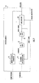
- the architecture of the JTRS software radio is designed, as shown in Fig. 1, in a modular manner in order to use commercial-off-the-shelf (COTS) components and thereby leverage COTS development and reduce the overall development costs of the JTRS software radio.
- the architecture depicted in Fig. 1 is a conceptual diagram illustrating major functional units, and does not necessarily illustrate physical relationships.
- the software radio notional architecture shown in Fig. 1 includes a red critical system interconnect (CSI) 1 and a black CSI 2.
- the red CSI couples functional entity interfaces (FEI), such as a user interface 3 or a network interface 4, to various red FEI units.
- FEI functional entity interfaces
- Those units can include a human-computer interface (HCI) 5, a red system control unit 6, an internetworking unit 7 and an information security (INFOSEC) unit 8.
- HCI human-computer interface
- HCI human-computer interface
- HCI human-computer interface
- a red system control unit 6 an internetworking unit 7
- an information security (INFOSEC) unit 8 information security
- the red CSI allows various types of red FEI units to be used on the red side of the radio.
- the internetworking unit 7, the red system control unit 6 and the HCI 5 can all reside on a single processor board 9, such as a Pentium class microprocessor circuit board that connects to the red CSI.
- the INFOSEC unit 8 connects to the black CSI on the black side of the software radio, and to the red CSI on the red side of the radio, and forms a boundary between the red and black environments.
- Connected to the black CSI are an antenna I/O interface unit 10 for sending and receiving RF signals, RF units 11, modems 12, and various other black side processes 13.
- a user interface 14 can be connected to the black CSI as shown in Fig. 1.
- the black CSI allows various types of COTS functional entity interface units to be used in the software radio, such as various types of commercial modems, for example.
- the internetworking unit 7 includes a router for routing messages, received from the user interfaces on the red side of the radio or received over the air after black side INFOSEC processing, to destinations on either the red or black sides of the radio. For destinations on the black side of the radio, the router must send the messages through the INFOSEC 8.
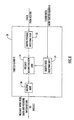
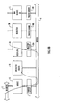
- FIG. 2 A multiple-input, multiple-output information system capable for use in the JTRS software radio is shown in Fig. 2 in which the INFOSEC unit 15 forms a boundary between red and black environments.
- the INFOSEC interfaces with input/output channels 1 through N.
- the INFOSEC interfaces with corresponding input/output channels 1 through N that connect to a router 16.
- the router 16 is coupled to a plurality of users, here, user 1 through user M.
- the data streams may be at different security/compartment levels if it is a government information system, or the data steams may belong to different communities of interest if in a commercial environment.
- the router 16 receives data, either from a user or from one of the channels, and routes it to the appropriate destination. For example, user 1 may send a message addressed to a destination reached using channel N.
- the router 16 using routing tables and routing algorithm software, receives the message from user 1 and based on the address determines a route over which to send the message. This entails attaching routing information to the message and outputting the message over the channel the router determines services the chosen route.
- the router 16 through the use of its routing tables and algorithms, determines that the message is to be output on channel N, for example. Accordingly, the router outputs the message on channel N with the added routing information attached to the message.
- the router when it receives a message on one of the N channels, it examines the routing information in the received message, determines the user or channel to which to send the message, and outputs the message to that user or channel. Because the router 16 receives data streams that may be at different security/compartment levels (government system) or may belong to different communities of interest (commercial system), the router in Fig. 2 must be tested to ensure it can be trusted with those data streams.
- an object of the invention is to use a router that has not been certified to process data of multiple security levels, to provide routing information for a message containing confidential data.
- a further object of the invention is to use routing information from an untrusted router to route confidential data without sending that data to the router.
- Yet another object of the invention is to generate a transmission frame by combining routing information from a dummy message sent to a router, with confidential information to be transported using the transmission frame.
- a still further object of the invention is to obtain routing information from a router that is not certified to handle information of multiple levels of security without sending confidential information to the router.
- a method in accordance with the invention routes a data message containing confidential information, by substituting dummy information for the confidential information in the message.
- the message is sent with the dummy information to a router for adding routing information to the message, and the confidential information is elsewhere substituted for the dummy information in the message containing the routing information.
- a trusted guard apparatus sends a data message to a router, in which the data message has information classified at a first security level.
- the apparatus includes a source authentication unit configured to receive the data message containing the information classified at the first security level, and to add to the data message source information concerning the source of the data message.
- the apparatus also includes a data integrity unit coupled to the source authentication unit and configured to transform the information classified at the first security level to include information for determining the integrity of the information classified at the first security level. It also includes a data substitution unit coupled to the source authentication unit and configured to generate a dummy data message by substituting dummy data for the information classified at the first security level, and outputting the dummy data message to the router.
- a transmission frame for delivering confidential data to a destination node includes a dummy data field containing dummy data, classified at a first security level, substituted for confidential data classified at a second security level different from the first security level.
- the transmission frame also includes a message header field containing information identifying the destination node, and a routing field containing routing information for use in routing the transmission frame to the destination node.
- source authentication When dealing with data processed by untrusted software between a source and a destination, it is necessary to prove at the destination point that the source information is accurate (source authentication) and that the data has not been modified (data integrity). If source authentication and data integrity are provided at the source and destination by trusted software and/or hardware entities, referred to here as trusted guards, then the untrusted router cannot interfere undetected with that information that is sent from the source to the destination and the trusted entities can enforce the computing system's security policy.
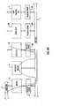
- Fig. 3 is a block diagram showing a trusted guard A 17 coupled with users 1 through M and coupled to ports 1 through M of the router 16.
- Another trusted guard B 18 is coupled to channels 1 through N of the router 16 and to the INFOSEC 15.
- Trusted guard B can be included as part of the INFOSEC 15.
- the trusted guard of Fig. 4 includes a labeling unit 19, a secure hashing algorithm (SHA) unit 20, a digital signature (DSS) unit 21 and a signature application unit 22.
- SHA secure hashing algorithm
- DSS digital signature
- the trusted guard's labeling unit 19 receives user data and source information and uses that information to attach a label to the data at its source.
- the label can include information about the source, such as, for example, a channel number, a security level, a packet number, the length of the packet and/or a time-of-day label.
- the trusted guard can add other information to the data such as a packet number, a time stamp or a unique identifier such as an identifier cryptographically generated by a trusted guard.
- the trusted guards are initialized by the INFOSEC, preferably at the time of powering on the trusted guards.
- the INFOSEC can initialize the trusted guards to operate at a specific security level depending on the guard's certification.
- the information provided by the labeling unit can be set at initialization.
- the SHA unit 20 can be used to reduce the amount of data by applying a hash algorithm to the labeled data and thereby reduce the computational complexity of the digital signature evaluation.
- Hashing can be used to reduce the complexity of using digital signatures, although it need not be used to practice the invention.
- the trusted guard can use well-known techniques to provide data integrity when sending data between trusted guards, such as by applying a digital signature to the labeled data.
- a digital signature can be a number computed from the data being signed.
- An example of a digital signature is a check-sum computed from the data and label.
- a cryptographic procedure is used instead of a checksum, to ensure that a signature cannot be modified.
- An example of such a cryptographic procedure that can be used to ensure the integrity of the data is the AFIPS-specified Digital Signature (DSS) which is based on Public Key Encryption.
- DSS Digital Signature
- the signature application unit 22 applies the signature to the labeled data received from the labeling unit 19, and outputs the labeled data with the signature as signed data.
- the trusted guard B 18, connected to the INFOSEC as shown in Fig. 3, receives the signed and labeled data from the router 16, authenticates it and verifies its integrity by using the signature and label in the data.
- the trusted guard system shown in Fig. 3 would suffice for routing messages to their destinations and ensuring that the security of the data is not compromised, if the untrusted router 16 were not allowed to generate data. If that were the case, and the router not allowed to generate data, the router would not be able to masquerade as a data source since the router could not generate signed data, as the source and destination are trusted and are the only ones that have the keys required by the DSS unit. However, the router 16 must be allowed to generate data, such as routing tables, and transmit them to other routers.
- the approach of labeling, hashing and signing data is insufficient to ensure that the router 16 cannot, through malicious or faulty software, hold on to data and then transmit that data as part of its own data transmissions, since that might cause data at a higher classification level to be released to users who are not authorized to see that data.
- the invention allows a router with untrusted software to be used in an MLS environment, yet ensures that the router does not release data from one security level to users or networks at a different level. This involves diverting data around the router that has the untrusted software, while using the router to supply routing information.
- An overall general process for using an untrusted router in an MLS environment is illustrated in Fig. 5. The process begins by trusted guard A receiving a message routed from a data source (23). The data in the message, which might be confidential and classified with a security level higher than a security level at which the router is certified, is removed and replaced with dummy data, such as a predetermined pattern of characters that is non-confidential (24).
- a pseudo random pattern can be cryptographically generated by the sending guard and validated by the receiving guard.
- the message with the dummy data i.e., a dummy data message
- the router 16 receives the dummy message, determines a route for it to travel to reach its intended destination, and appends to the dummy message routing information specifying such a route (26).
- the router sends the dummy message with the routing information to trusted guard B where the data is diverted (27).
- Trusted guard B then replaces the dummy data in the message to which the routing information is appended with the data from the data source (28). Trusted guard B then sends the reconstructed message according to the routing information supplied by the router (29). In this manner, a router 16 with untrusted software is used to supply routing information without the untrusted router receiving data from the data source.
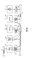
- a trusted guard A 30 coupled to users 1 through M and to the router, receives a message with data for delivery to a destination specified by an address in a header of the message.
- a detailed view of trusted guard A 19 is shown in Fig. 7.
- trusted guard A 30 also includes a dummy message generator 32.
- the trusted guard A compresses the labeled data using a hash algorithm or another data compression technique.
- Trusted guard A 30 sends the signed data (i.e., data + label + signature) over a trusted path that does not include the router, to a trusted guard B 31 that is coupled to the router 16 and INFOSEC 15.
- the dummy generator 32 receives the message supplied to trusted guard 30 from the user and replaces the data in the message with non-confidential dummy data that is classified at a security level the same as or lower than the security level of the router, and retains any headers in the message.
- An example of such non-confidential data is a predetermined pattern of characters or a pseudo random pattern that is cryptographically generated.
- the dummy message generator 32 can receive the message at any point in the trusted guard, so long as the message's header remains intact. Trusted guard A 30 then outputs the dummy message having the headers and non-confidential dummy data, to the router 16.
- the router 16 receives the dummy message and based on the headers in the message determines a route for delivering the message to the intended destination. The router 16 then applies to the dummy message routing information specifying the determined route. For example, the router can apply the routing information by appending it to the dummy message. The router 16 then outputs the dummy message with the routing information to trusted guard B 31.
- Trusted guard B 31 is shown in detail in Fig. 8 and includes a dummy message receiving unit 33, a signed data receiving unit 34, a message reconstruction unit 35, and an output unit 36.
- Signed data receiving unit 34 receives the signed data sent from the trusted guard A 30 and sends it to the message reconstruction unit 35 which holds it until the dummy message receiving unit 33 receives the corresponding dummy message from the router 16.
- the message reconstruction unit 35 then receives the signed data, matches headers, and replaces the dummy data with the signed data to form a reconstructed message.
- the reconstructed message includes the routing information, any original message headers and the signed data.
- the output unit 36 then outputs the reconstructed message to the INFOSEC 15, which performs conventional red/black isolation functions, and forwards the message to the intended destination along a path specified by the routing information.
- the destination upon receiving the message uses its keys to unhash and authenticate the message. In this manner the message is routed and verified at the destination.
- Trusted guard A can include the same structure and perform the same functions as trusted guard B, shown in Fig. 8, where trusted guard A also receives data from another trusted guard.
- trusted guard B can include the same structure and perform the same functions as trusted guard A, shown in Fig. 7, where trusted guard B also sends data to another trusted guard.
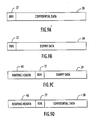
- Figs. 9A-9D show examples of messages sent from the source through the trusted guard A and the untrusted router to the INFOSEC.
- a user for example user 1 shown in Fig. 6, sends a message shown in Fig. 9A that contains data 38 that could be confidential and classified at a security level higher than a level at which the router is certified.
- the message in Fig. 9A also includes standard headers (HDR) 37 attached to the confidential data according to the networking protocols in use.
- Trusted guard 30, upon receiving the confidential data substitutes dummy data 39 for the confidential data and sends a dummy message, shown in Fig. 9B, to the router 16.
- the router 16 upon receiving the dummy message adds a routing header 40 to the dummy data 39 and header 37.
- the routing header 40 includes routing information for routing the message to the destination.
- the router 16 sends the dummy data message with the routing header, shown in Fig. 9C, to trusted guard B 31 by way of the appropriate channel according to the determined route
- Trusted guard A 30 sends the confidential data 38 that has been separated from the original message to trusted guard B 31.
- trusted guard A 30 can apply a hashing function to the confidential data, and can also apply a digital signature to the data.
- Trusted guard A 30 sends the signed confidential data to trusted guard B 31 by way of a trusted path separate from the router.
- Trusted guard B 31 matches the signed data with the dummy message received from the router that contains the routing header 40. Trusted guard B 31 substitutes the signed confidential data 38 received from the trusted guard A 30 for the dummy data 39 contained in the message received from the router16. Thus, trusted guard B 31 forms the message, or transmission frame, shown in Fig. 9D that includes the routing header 40 that contains the routing information for delivering the message to the intended destination, the original headers 37 and the confidential data 38. Trusted guard B 31 then sends the message shown in Fig. 9D to the INFOSEC for transmission to the destination along the determined route.
- the process described above also operates in the reverse direction. When information arrives from channels 1 through N it is provided to one of the users 1 through M. In that case, trusted guards A and B operate with their roles reversed.
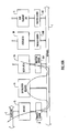
- the trusted guards described above can be used in a variety of data flow scenarios for delivering data both to the red side and the black side of INFOSEC 15.
- Various such data flows are shown in Figs. 10A through 10G, in which the data flows represented by a solid line designate messages that contain data from a source, such as red data from a user.
- the dashed lines depict data flow of messages containing dummy data.
- the data flow shown in Fig. 10A depicts a message originating from the red side of the INFOSEC and flowing to a destination on the black side.
- a user A sends a message containing red data through the user A's I/O device 3A to a trusted guard 30A and over the red bus 1 to trusted guard 31 to INFOSEC 15 for delivery to a destination over black bus 2.
- trusted guard 30A substitutes dummy data for the red data in the message to create a dummy message.
- Trusted guard 30A sends the dummy message to untrusted router 16 which adds routing information to the dummy message, as depicted by the dashed line. The router 16 sends the dummy message with the routing information to trusted guard 31.
- trusted guard 30A sends the message data to the trusted guard 31 across red bus 1, as depicted by the solid line.
- Trusted guard 31 then reconstructs the message by combining the routing information in the dummy message with the red data received from trusted guard 30A.
- Trusted guard 31 then sends the reconstructed message to the INFOSEC for delivery to a transmitter on the black bus 2.
- a message sent from a source outside the local red environment shown in Fig. 10B is received by INFOSEC 15 from black bus 2.
- the message likely in the form of a data packet, is received by the radio's antenna and demodulated on the black side of the INFOSEC 15.
- the demodulator forwards the message to the INFOSEC 15 over the black bus 2 and the INFOSEC 15 passes the received message to trusted guard 31.
- the trusted guard 31 generates a dummy message with the header information from the received message and dummy data substituted for the data in the message, and forwards the dummy message to untrusted router 16, as depicted by the dashed line.
- the INFOSEC 15 decrypts the message's data and passes the decrypted data to trusted guard 31.
- the router 16 returns the I/O address for the destination to the trusted guard 31. In the example shown in Fig. 10B the router returns the I/O address for user A's I/O device 3A.
- the trusted guard 31 then verifies the messages destination, and assembles the decrypted data with the header information returned from the router. Before sending the decrypted data to the destination I/O device indicated by the header information returned from the router, the trusted guard 31 verifies that the indicated destination is authorized to receive information at the security level of the decrypted data. Once verified the trusted guard 31 hashes and signs the message and sends the assembled message with the decrypted data to the destination I/O device via the red bus 1, here, user A's I/O device 3A, as depicted by the solid line.
- the data flow shown in Fig. 10B can be achieved by router 16 forwarding the dummy message to the trusted guard servicing the destination I/O device as shown in Fig. 10C.
- trusted guard 31 places the data from the received message on the red bus 1 with some type of identifier, such as, for example, a packet number, date/time stamp, etc.
- the dummy message generated by trusted guard 31 would have the same identifier (e.g., packet number, date/time stamp, etc.). All trusted guards on red bus 1 would see the data placed on the red bus, but only the guard(s) to which the dummy message is sent will take the data off the red bus and supply it to the respective user I/O device.
- the trusted guard(s) that receive the dummy message can detect the corresponding data on the red bus by matching the identifiers (e.g., packet number, date/time stamp, etc.)
- identifiers e.g., packet number, date/time stamp, etc.
- user A's I/O device 3A receives the dummy message thus indicating that it is to receive the data placed on the bus.
- Trusted guard 30A matches identifying information from the dummy message with the data on the red bus, and if there is a match it takes the data off the red bus, authenticates it and supplies the data to user A's I/O device 3A.
- the other trusted guards ignore the data on the red bus because they did not receive the dummy message from the router 16.
- the other trusted guards also ignore the data, if the data is labeled, because the attached label does not indicate that the data is destined for them.
- Fig. 10D depicts a data flow for the case in which a message is routed only within the red environment of the communication system.
- user A sends a message, via user A's I/O device 3A, to user B.
- Trusted guard 30A receives the message from user A's I/O device 3A and substitutes dummy data for the red data in the message. The dummy message is sent to untrusted router 16 for application of routing information to the message, as depicted by the dashed line.
- Trusted guard 30A sends the message's red data to the INFOSEC 15 by way of trusted guard 31.
- the router 16 adds routing information to the dummy message and then sends it to the trusted guard that services INFOSEC 15, i.e., trusted guard 31.
- trusted guard 31 reconstructs the message by assembling the red data with the header information received from the untrusted router 16 that contains the routing information. Trusted guard 31 forwards the reconstructed message data and header to the destination user I/O device indicated in the routing information, as depicted by the solid line. In the example shown in Fig.
- the message is destined for user B, and accordingly, the reconstructed message is forwarded to user B's I/O device 3B via trusted guard 30B.
- the trusted guard 30B verifies that the data in the message is at the proper classification level for the destination indicated by the routing information.
- the message can be routed without sending the data to either the router 16 or the INFOSEC 15.
- the untrusted router 16 upon receiving the dummy message and determining the appropriate routing information can notify the destination trusted guard, in this example, trusted guard 30B, that the message is intended for user B.
- the router 16 can notify the destination trusted guard by sending it the dummy data message, as shown by the dashed line in Fig. 10E, with the routing information included in that message. This notification can occur by the router 16 routing the dummy data message to the destination.
- trusted guard 30A When the source trusted guard, in this example, trusted guard 30A, substitutes dummy data for the message data, it can place the message data on the red bus 1 for all trusted guards to see, as shown by the solid line. As described above, trusted guard 30A can add identifying information to both the dummy data message and the message data to facilitate later matching. Only the trusted guard receiving the dummy data message from the router, here trusted guard 30B, will then identify the data on the red bus 1 as matching the dummy data message and take the message data off of red bus 1. The destination trusted guard can verify and authenticate the data, and allow the message data to be passed to user B only if user B is authorized to access the message data.
- FIG. 10F Another data flow example is shown in Fig. 10F.
- the data path is the same as shown in Fig. 10D except the encryption/decryption requirements are different. That is, here, user A sends a message intended for user B, however the message must be encrypted due to channel setup requirements designated at instantiation.
- trusted guard 30A separates the message data from the message's header information and uses that header information to generate a dummy message containing dummy data.
- the dummy message with the message's header information, is sent to untrusted router 16 to add routing information, as shown by the dashed line.
- the message data is supplied to INFOSEC 15 via trusted guard 31, as shown by the solid line.
- the untrusted router upon determining the appropriate route, provides the routing information to trusted guard 31, preferably in the form of routing information added to the header of the dummy message.
- the untrusted router 16 then sends the dummy message to trusted guard 31, as depicted by the dashed line.
- the message must be encrypted or decrypted since the user's encryption/decryption requirements are different.
- INFOSEC 15 performs the appropriate encryption/decryption on the message data according to the channel setup requirements for users A and B, and supplies the appropriately encrypted or decrypted message data to trusted guard 31.
- Trusted guard 31 then adds the routing information supplied by untrusted router 16 to the message data that is to be delivered to user B, thereby reconstructing the message.
- the trusted guard 31 sends the reconstructed message to user B according to the routing information, as depicted by the solid line.
- Trusted guard 30B receives the reconstructed message and verifies and authenticates the message before supplying it to user B's I/O device 3B.
- trusted guard 30A can send the message data to the INFOSEC 15, as depicted by the solid line, for encryption/decryption.
- the INFOSEC 15, after encrypting/decrypting the message data can place that data on red bus 1 via trusted guard 31.
- the router 16 can notify the destination trusted guard of the message, such as by sending the dummy message to the destination trusted guard, in this example, trusted guard 30B, as depicted by the dashed line.
- the destination trusted guard, here, trusted guard 30B upon receiving the dummy message matches identifying information in the dummy message with identifying information in the data on the red bus.
- trusted guard B takes the encrypted/decrypted data off of red bus 1.
- Trusted guard 30B verifies and authenticates the message data and supplies it to user B's I/O device if it's security level is adequate for the security classification of the message data.
- the functions of the trusted guards, and the units within the trusted guards such as the units shown in Figs. 7 and 8, can be performed using computer programs controlling computer hardware and firmware. It will also be understood that such computer programs can be recorded on computer-readable media, such as magnetic and optical disks, and can be transmitted in a computer-readable signal.
Abstract
Description
- The invention relates to network communications methods and systems. More particularly, it relates to routing data of multiple levels of security in a data communication network.
- Over the past several years the world has witnessed tremendous advances in commercial networking technologies. Many of the advances concern routing techniques and devices used in commercial networks, and networks of networks often referred to as the Internet. Typically, commercial routers are used in unsecured environments, at least from a data perspective. That is, commercial routers have been developed for commercial use without regard to supporting information classified according to multiple levels of security. Although commercial routing devices typically undergo many reliability and quality tests, they are not designed, nor are they tested, with the goal of handling multiple levels of security classification.
- In contrast to commercial environments, networking devices for use in military applications are often required to support multiple levels of security classification. Multilevel security (MLS), according to the National Information Systems Security (INFOSEC) Glossary, NSTISSI No. 4009, January 1999 (Rev. 1), is a concept of processing information with different classifications and categories that simultaneously permits access by users with different security clearances and denies access to users who lack authorization. Multilevel security and MLS, as used here, encompass simultaneous access by users with different levels of access authority that is not necessarily limited to a national security clearance level.
- Information classified according to a government or military organization's security classification is referred to here as classified information. Information used in a commercial environment and to which access is to be limited is referred to as proprietary information. More generally, confidential information refers to information to which access is to be limited and encompasses both classified and proprietary information.
- In an MLS environment, it is important to use a trusted computing system, which refers to the totality of protection mechanisms within a computer system, including hardware, firmware, and software, that is, the combination responsible for enforcing an organization's security policy. In many trusted computing systems that process sensitive or classified information, especially national security information, information systems' security methods and devices are used to protect the information systems against unauthorized access to or modification of information, whether in storage, processing or transit, and against the denial of service to authorized users, including those measures necessary to detect, document and counter such threats. Such information systems often employ red/black concepts and techniques. "Red/black" refers to separation of electrical and electronic circuits, components, equipment, and systems that handle national security information (red) in electrical form from those that handle non-national security information (black) in the same form, as described in the National INFOSEC Glossary. Devices and software components that operate in a red environment for processing classified data undergo extensive testing to ensure the integrity of the classified data passing through those components. Such testing can be very lengthy and very expensive.
- Unfortunately, because of the extensive design and testing to ensure the integrity of red data, many military computing systems have not been able to take full advantage of the tremendous advances in routing technology taking place in the commercial networking world. Accordingly, there is a need to use commercial networking equipment, particularly network routers, in computing environments that must support MLS systems, yet without requiring the extensive testing to certify that equipment to process red data. Hence, there is a need to employ untrusted commercial network routers in computing systems that handle multilevel security data.
- A Joint Tactical Radio System (JTRS) software radio is an example of equipment that must operate in a MLS environment. A software radio is a radio that uses computer software to perform a variety of functions in the process of converting voice or data information to and from a radio frequency (RF) signal. The architecture of the JTRS software radio is designed, as shown in Fig. 1, in a modular manner in order to use commercial-off-the-shelf (COTS) components and thereby leverage COTS development and reduce the overall development costs of the JTRS software radio. The architecture depicted in Fig. 1 is a conceptual diagram illustrating major functional units, and does not necessarily illustrate physical relationships.
- The software radio notional architecture shown in Fig. 1 includes a red critical system interconnect (CSI) 1 and a
black CSI 2. The red CSI couples functional entity interfaces (FEI), such as a user interface 3 or anetwork interface 4, to various red FEI units. Those units can include a human-computer interface (HCI) 5, a red system control unit 6, an internetworking unit 7 and an information security (INFOSEC) unit 8. The red CSI allows various types of red FEI units to be used on the red side of the radio. For example, the internetworking unit 7, the red system control unit 6 and the HCI 5 can all reside on asingle processor board 9, such as a Pentium class microprocessor circuit board that connects to the red CSI. - The INFOSEC unit 8 connects to the black CSI on the black side of the software radio, and to the red CSI on the red side of the radio, and forms a boundary between the red and black environments. Connected to the black CSI are an antenna I/
O interface unit 10 for sending and receiving RF signals, RF units 11, modems 12, and various otherblack side processes 13. Also, auser interface 14 can be connected to the black CSI as shown in Fig. 1. The black CSI allows various types of COTS functional entity interface units to be used in the software radio, such as various types of commercial modems, for example. - The internetworking unit 7 includes a router for routing messages, received from the user interfaces on the red side of the radio or received over the air after black side INFOSEC processing, to destinations on either the red or black sides of the radio. For destinations on the black side of the radio, the router must send the messages through the INFOSEC 8.
- A multiple-input, multiple-output information system capable for use in the JTRS software radio is shown in Fig. 2 in which the INFOSEC
unit 15 forms a boundary between red and black environments. On the black side of the system the INFOSEC interfaces with input/output channels 1 through N. Similarly, on the red side of the system the INFOSEC interfaces with corresponding input/output channels 1 through N that connect to arouter 16. Therouter 16 is coupled to a plurality of users, here, user 1 through user M. In such an environment the data streams may be at different security/compartment levels if it is a government information system, or the data steams may belong to different communities of interest if in a commercial environment. - The
router 16 receives data, either from a user or from one of the channels, and routes it to the appropriate destination. For example, user 1 may send a message addressed to a destination reached using channel N. Therouter 16, using routing tables and routing algorithm software, receives the message from user 1 and based on the address determines a route over which to send the message. This entails attaching routing information to the message and outputting the message over the channel the router determines services the chosen route. Therouter 16, through the use of its routing tables and algorithms, determines that the message is to be output on channel N, for example. Accordingly, the router outputs the message on channel N with the added routing information attached to the message. Similarly, when the router receives a message on one of the N channels, it examines the routing information in the received message, determines the user or channel to which to send the message, and outputs the message to that user or channel. Because therouter 16 receives data streams that may be at different security/compartment levels (government system) or may belong to different communities of interest (commercial system), the router in Fig. 2 must be tested to ensure it can be trusted with those data streams. - It is highly desirable to use standard commercial software for the router because of the rapid technological advances and routing evolution occurring in the commercial sector. However, commercial routing software does not undergo the rigorous and extensive testing required to certify it as trusted and therefore a commercial router has no level of trust. Yet, there is a strongly felt need to develop an approach that uses commercial routing techniques and software in an MLS environment and guarantees that data from one security level will not get released to users or networks at a different level without following the safeguards specified by the information system's security policy.
- Therefore, in light of the above, and for other reasons that will become apparent when the invention is fully described, an object of the invention is to use a router that has not been certified to process data of multiple security levels, to provide routing information for a message containing confidential data.
- A further object of the invention is to use routing information from an untrusted router to route confidential data without sending that data to the router.
- Yet another object of the invention is to generate a transmission frame by combining routing information from a dummy message sent to a router, with confidential information to be transported using the transmission frame.
- A still further object of the invention is to obtain routing information from a router that is not certified to handle information of multiple levels of security without sending confidential information to the router.
- The aforesaid objects are achieved individually and in combination, and it is not intended that the invention be construed as requiring two or more of the objects to be combined unless expressly required by the claims attached hereto.
- A method in accordance with the invention routes a data message containing confidential information, by substituting dummy information for the confidential information in the message. The message is sent with the dummy information to a router for adding routing information to the message, and the confidential information is elsewhere substituted for the dummy information in the message containing the routing information.
- A trusted guard apparatus, according to the invention, sends a data message to a router, in which the data message has information classified at a first security level. The apparatus includes a source authentication unit configured to receive the data message containing the information classified at the first security level, and to add to the data message source information concerning the source of the data message. The apparatus also includes a data integrity unit coupled to the source authentication unit and configured to transform the information classified at the first security level to include information for determining the integrity of the information classified at the first security level. It also includes a data substitution unit coupled to the source authentication unit and configured to generate a dummy data message by substituting dummy data for the information classified at the first security level, and outputting the dummy data message to the router.
- A transmission frame for delivering confidential data to a destination node, according to the invention, includes a dummy data field containing dummy data, classified at a first security level, substituted for confidential data classified at a second security level different from the first security level. The transmission frame also includes a message header field containing information identifying the destination node, and a routing field containing routing information for use in routing the transmission frame to the destination node.
- The above and still further objects, features and advantages of the invention will become apparent upon consideration of the following descriptions and descriptive figures of specific embodiments thereof. While these descriptions go into specific details of the invention, it should be understood that variations may and do exist and would be apparent to those skilled in the art based on the descriptions herein.
-
- Fig. 1 is a block diagram illustrating an architecture of a software radio.
- Fig. 2 is a block diagram of a portion of a computing system, such as the software radio of Fig. 1, using a router and an INFOSEC.
- Fig. 3 is a block diagram of a computing system using an untrusted router in combination with an INFOSEC and a trusted guard unit.
- Fig. 4 is a diagram showing a detailed view of a trusted guard unit A.
- Fig. 5 is a flowchart illustrating a process of routing data according to the invention.
- Fig. 6 is a block diagram of a computing system using an untrusted router, a trusted guard unit and showing data flows according to certain aspects of the invention.
- Fig. 7 is a detailed view of a trusted guard with a dummy message generator.
- Fig. 8 is a detailed view of a trusted guard unit that combines routing information from an untrusted router with signed data from another trusted guard unit.
- Figs. 9A-D are diagrams of data packets at various stages of a routing process according to aspects of the invention.
- Fig. 10A-G are diagrams illustrating various data flows in a software radio.
-
- Preferred embodiments according to the present invention are described below with reference to the above drawings, in which like reference numerals designate like components.
- When dealing with data processed by untrusted software between a source and a destination, it is necessary to prove at the destination point that the source information is accurate (source authentication) and that the data has not been modified (data integrity). If source authentication and data integrity are provided at the source and destination by trusted software and/or hardware entities, referred to here as trusted guards, then the untrusted router cannot interfere undetected with that information that is sent from the source to the destination and the trusted entities can enforce the computing system's security policy.
- Fig. 3 is a block diagram showing a trusted
guard A 17 coupled with users 1 through M and coupled to ports 1 through M of therouter 16. Another trustedguard B 18 is coupled to channels 1 through N of therouter 16 and to theINFOSEC 15. Trusted guard B can be included as part of theINFOSEC 15. - A block diagram of trusted guard A is shown in Fig. 4. The trusted guard of Fig. 4 includes a
labeling unit 19, a secure hashing algorithm (SHA)unit 20, a digital signature (DSS)unit 21 and asignature application unit 22. To provide source authentication the trusted guard'slabeling unit 19 receives user data and source information and uses that information to attach a label to the data at its source. The label can include information about the source, such as, for example, a channel number, a security level, a packet number, the length of the packet and/or a time-of-day label. Further, if assurance requirements so dictate, the trusted guard can add other information to the data such as a packet number, a time stamp or a unique identifier such as an identifier cryptographically generated by a trusted guard. The trusted guards are initialized by the INFOSEC, preferably at the time of powering on the trusted guards. For example, the INFOSEC can initialize the trusted guards to operate at a specific security level depending on the guard's certification. The information provided by the labeling unit can be set at initialization. TheSHA unit 20 can be used to reduce the amount of data by applying a hash algorithm to the labeled data and thereby reduce the computational complexity of the digital signature evaluation. Hashing can be used to reduce the complexity of using digital signatures, although it need not be used to practice the invention. The trusted guard can use well-known techniques to provide data integrity when sending data between trusted guards, such as by applying a digital signature to the labeled data. For example, a digital signature can be a number computed from the data being signed. An example of a digital signature is a check-sum computed from the data and label. Generally, however, a cryptographic procedure is used instead of a checksum, to ensure that a signature cannot be modified. An example of such a cryptographic procedure that can be used to ensure the integrity of the data is the AFIPS-specified Digital Signature (DSS) which is based on Public Key Encryption. TheDSS unit 21 shown in Fig. 4 determines and outputs such a digital signature for the labeled data. Thesignature application unit 22 applies the signature to the labeled data received from thelabeling unit 19, and outputs the labeled data with the signature as signed data. The trustedguard B 18, connected to the INFOSEC as shown in Fig. 3, receives the signed and labeled data from therouter 16, authenticates it and verifies its integrity by using the signature and label in the data. - The trusted guard system shown in Fig. 3 would suffice for routing messages to their destinations and ensuring that the security of the data is not compromised, if the
untrusted router 16 were not allowed to generate data. If that were the case, and the router not allowed to generate data, the router would not be able to masquerade as a data source since the router could not generate signed data, as the source and destination are trusted and are the only ones that have the keys required by the DSS unit. However, therouter 16 must be allowed to generate data, such as routing tables, and transmit them to other routers. Accordingly, the approach of labeling, hashing and signing data is insufficient to ensure that therouter 16 cannot, through malicious or faulty software, hold on to data and then transmit that data as part of its own data transmissions, since that might cause data at a higher classification level to be released to users who are not authorized to see that data. - The invention allows a router with untrusted software to be used in an MLS environment, yet ensures that the router does not release data from one security level to users or networks at a different level. This involves diverting data around the router that has the untrusted software, while using the router to supply routing information. An overall general process for using an untrusted router in an MLS environment is illustrated in Fig. 5. The process begins by trusted guard A receiving a message routed from a data source (23). The data in the message, which might be confidential and classified with a security level higher than a security level at which the router is certified, is removed and replaced with dummy data, such as a predetermined pattern of characters that is non-confidential (24). Alternatively, a pseudo random pattern can be cryptographically generated by the sending guard and validated by the receiving guard. The message with the dummy data (i.e., a dummy data message) is sent to the
router 16, and the data removed from the message is directed around theuntrusted router 16 and sent to trusted guard B to eventually match it with the dummy message once therouter 16 determines the routing information (25). Therouter 16 receives the dummy message, determines a route for it to travel to reach its intended destination, and appends to the dummy message routing information specifying such a route (26). The router sends the dummy message with the routing information to trusted guard B where the data is diverted (27). Trusted guard B then replaces the dummy data in the message to which the routing information is appended with the data from the data source (28). Trusted guard B then sends the reconstructed message according to the routing information supplied by the router (29). In this manner, arouter 16 with untrusted software is used to supply routing information without the untrusted router receiving data from the data source. - The operation of the untrusted router system of Fig. 3 is modified to perform a data diversion technique, as illustrated in Fig. 6. In the system shown in Fig. 6 a trusted
guard A 30, coupled to users 1 through M and to the router, receives a message with data for delivery to a destination specified by an address in a header of the message. A detailed view of trustedguard A 19 is shown in Fig. 7. In addition to the trusted guard shown in Fig. 4, trustedguard A 30 also includes adummy message generator 32.Trusted guard A 30, as described above, labels and applies a signature to the data. Alternatively, the trusted guard A compresses the labeled data using a hash algorithm or another data compression technique.Trusted guard A 30 sends the signed data (i.e., data + label + signature) over a trusted path that does not include the router, to a trustedguard B 31 that is coupled to therouter 16 andINFOSEC 15. Thedummy generator 32 receives the message supplied to trustedguard 30 from the user and replaces the data in the message with non-confidential dummy data that is classified at a security level the same as or lower than the security level of the router, and retains any headers in the message. An example of such non-confidential data is a predetermined pattern of characters or a pseudo random pattern that is cryptographically generated. Alternatively, thedummy message generator 32 can receive the message at any point in the trusted guard, so long as the message's header remains intact.Trusted guard A 30 then outputs the dummy message having the headers and non-confidential dummy data, to therouter 16. - The
router 16 receives the dummy message and based on the headers in the message determines a route for delivering the message to the intended destination. Therouter 16 then applies to the dummy message routing information specifying the determined route. For example, the router can apply the routing information by appending it to the dummy message. Therouter 16 then outputs the dummy message with the routing information to trustedguard B 31. -
Trusted guard B 31 is shown in detail in Fig. 8 and includes a dummymessage receiving unit 33, a signeddata receiving unit 34, amessage reconstruction unit 35, and anoutput unit 36. Signeddata receiving unit 34 receives the signed data sent from the trustedguard A 30 and sends it to themessage reconstruction unit 35 which holds it until the dummymessage receiving unit 33 receives the corresponding dummy message from therouter 16. Themessage reconstruction unit 35 then receives the signed data, matches headers, and replaces the dummy data with the signed data to form a reconstructed message. The reconstructed message includes the routing information, any original message headers and the signed data. Theoutput unit 36 then outputs the reconstructed message to theINFOSEC 15, which performs conventional red/black isolation functions, and forwards the message to the intended destination along a path specified by the routing information. - Since the source and destination are trusted and are the only ones that have the keys required by the digital signature algorithms, the destination upon receiving the message uses its keys to unhash and authenticate the message. In this manner the message is routed and verified at the destination.
- Trusted guard A can include the same structure and perform the same functions as trusted guard B, shown in Fig. 8, where trusted guard A also receives data from another trusted guard. Likewise, trusted guard B can include the same structure and perform the same functions as trusted guard A, shown in Fig. 7, where trusted guard B also sends data to another trusted guard.
- Figs. 9A-9D show examples of messages sent from the source through the trusted guard A and the untrusted router to the INFOSEC. A user, for example user 1 shown in Fig. 6, sends a message shown in Fig. 9A that contains
data 38 that could be confidential and classified at a security level higher than a level at which the router is certified. The message in Fig. 9A also includes standard headers (HDR) 37 attached to the confidential data according to the networking protocols in use.Trusted guard 30, upon receiving the confidential data substitutesdummy data 39 for the confidential data and sends a dummy message, shown in Fig. 9B, to therouter 16. Therouter 16, upon receiving the dummy message adds arouting header 40 to thedummy data 39 andheader 37. Therouting header 40 includes routing information for routing the message to the destination. Therouter 16 sends the dummy data message with the routing header, shown in Fig. 9C, to trustedguard B 31 by way of the appropriate channel according to the determined route. -
Trusted guard A 30 sends theconfidential data 38 that has been separated from the original message to trustedguard B 31. As discussed above, trustedguard A 30 can apply a hashing function to the confidential data, and can also apply a digital signature to the data.Trusted guard A 30 sends the signed confidential data to trustedguard B 31 by way of a trusted path separate from the router. -
Trusted guard B 31 matches the signed data with the dummy message received from the router that contains therouting header 40.Trusted guard B 31 substitutes the signedconfidential data 38 received from the trustedguard A 30 for thedummy data 39 contained in the message received from the router16. Thus, trustedguard B 31 forms the message, or transmission frame, shown in Fig. 9D that includes therouting header 40 that contains the routing information for delivering the message to the intended destination, theoriginal headers 37 and theconfidential data 38.Trusted guard B 31 then sends the message shown in Fig. 9D to the INFOSEC for transmission to the destination along the determined route. The process described above also operates in the reverse direction. When information arrives from channels 1 through N it is provided to one of the users 1 through M. In that case, trusted guards A and B operate with their roles reversed. - The trusted guards described above can be used in a variety of data flow scenarios for delivering data both to the red side and the black side of
INFOSEC 15. Various such data flows are shown in Figs. 10A through 10G, in which the data flows represented by a solid line designate messages that contain data from a source, such as red data from a user. The dashed lines depict data flow of messages containing dummy data. - The data flow shown in Fig. 10A depicts a message originating from the red side of the INFOSEC and flowing to a destination on the black side. Here, a user A sends a message containing red data through the user A's I/
O device 3A to a trustedguard 30A and over the red bus 1 to trustedguard 31 toINFOSEC 15 for delivery to a destination overblack bus 2. In the manner described above, trustedguard 30A substitutes dummy data for the red data in the message to create a dummy message.Trusted guard 30A sends the dummy message tountrusted router 16 which adds routing information to the dummy message, as depicted by the dashed line. Therouter 16 sends the dummy message with the routing information to trustedguard 31. Meanwhile, trustedguard 30A sends the message data to the trustedguard 31 across red bus 1, as depicted by the solid line.Trusted guard 31 then reconstructs the message by combining the routing information in the dummy message with the red data received from trustedguard 30A.Trusted guard 31 then sends the reconstructed message to the INFOSEC for delivery to a transmitter on theblack bus 2. - Data flowing in the reverse direction is shown in Fig. 10B. Here, a message sent from a source outside the local red environment shown in Fig. 10B is received by
INFOSEC 15 fromblack bus 2. In the case of the JTRS software radio the message, likely in the form of a data packet, is received by the radio's antenna and demodulated on the black side of theINFOSEC 15. The demodulator forwards the message to theINFOSEC 15 over theblack bus 2 and theINFOSEC 15 passes the received message to trustedguard 31. The trustedguard 31 generates a dummy message with the header information from the received message and dummy data substituted for the data in the message, and forwards the dummy message tountrusted router 16, as depicted by the dashed line. TheINFOSEC 15 decrypts the message's data and passes the decrypted data to trustedguard 31. Therouter 16 returns the I/O address for the destination to the trustedguard 31. In the example shown in Fig. 10B the router returns the I/O address for user A's I/O device 3A. The trustedguard 31 then verifies the messages destination, and assembles the decrypted data with the header information returned from the router. Before sending the decrypted data to the destination I/O device indicated by the header information returned from the router, the trustedguard 31 verifies that the indicated destination is authorized to receive information at the security level of the decrypted data. Once verified the trustedguard 31 hashes and signs the message and sends the assembled message with the decrypted data to the destination I/O device via the red bus 1, here, user A's I/O device 3A, as depicted by the solid line. - Alternatively, the data flow shown in Fig. 10B can be achieved by
router 16 forwarding the dummy message to the trusted guard servicing the destination I/O device as shown in Fig. 10C. Here, trustedguard 31 places the data from the received message on the red bus 1 with some type of identifier, such as, for example, a packet number, date/time stamp, etc. The dummy message generated by trustedguard 31 would have the same identifier (e.g., packet number, date/time stamp, etc.). All trusted guards on red bus 1 would see the data placed on the red bus, but only the guard(s) to which the dummy message is sent will take the data off the red bus and supply it to the respective user I/O device. The trusted guard(s) that receive the dummy message can detect the corresponding data on the red bus by matching the identifiers (e.g., packet number, date/time stamp, etc.) In the example shown in Fig. 10C, user A's I/O device 3A receives the dummy message thus indicating that it is to receive the data placed on the bus.Trusted guard 30A then matches identifying information from the dummy message with the data on the red bus, and if there is a match it takes the data off the red bus, authenticates it and supplies the data to user A's I/O device 3A. The other trusted guards ignore the data on the red bus because they did not receive the dummy message from therouter 16. The other trusted guards also ignore the data, if the data is labeled, because the attached label does not indicate that the data is destined for them. - Fig. 10D depicts a data flow for the case in which a message is routed only within the red environment of the communication system. In Fig. 10D user A sends a message, via user A's I/
O device 3A, to user B. Trustedguard 30A receives the message from user A's I/O device 3A and substitutes dummy data for the red data in the message. The dummy message is sent tountrusted router 16 for application of routing information to the message, as depicted by the dashed line.Trusted guard 30A sends the message's red data to theINFOSEC 15 by way of trustedguard 31. Therouter 16 adds routing information to the dummy message and then sends it to the trusted guard that servicesINFOSEC 15, i.e., trustedguard 31. If the message's destination is local, that is, within the red environment shown in Fig. 10D, and the encryption requirements are the same for both users (e.g., not requiring radio transmission), then the message need not be sent toINFOSEC 15 for encryption/decryption services. Accordingly, trustedguard 31 reconstructs the message by assembling the red data with the header information received from theuntrusted router 16 that contains the routing information.Trusted guard 31 forwards the reconstructed message data and header to the destination user I/O device indicated in the routing information, as depicted by the solid line. In the example shown in Fig. 10D the message is destined for user B, and accordingly, the reconstructed message is forwarded to user B's I/O device 3B via trustedguard 30B. Before allowing the message data to be released to user B's I/O device, the trustedguard 30B verifies that the data in the message is at the proper classification level for the destination indicated by the routing information. - Alternatively, in situations where security access controls do not require the function of
INFOSEC 15, the message can be routed without sending the data to either therouter 16 or theINFOSEC 15. In that case, depicted in Fig. 10E, when sending a message between users in the same red environment theuntrusted router 16 upon receiving the dummy message and determining the appropriate routing information can notify the destination trusted guard, in this example, trustedguard 30B, that the message is intended for user B. Therouter 16 can notify the destination trusted guard by sending it the dummy data message, as shown by the dashed line in Fig. 10E, with the routing information included in that message. This notification can occur by therouter 16 routing the dummy data message to the destination. When the source trusted guard, in this example, trustedguard 30A, substitutes dummy data for the message data, it can place the message data on the red bus 1 for all trusted guards to see, as shown by the solid line. As described above, trustedguard 30A can add identifying information to both the dummy data message and the message data to facilitate later matching. Only the trusted guard receiving the dummy data message from the router, here trustedguard 30B, will then identify the data on the red bus 1 as matching the dummy data message and take the message data off of red bus 1. The destination trusted guard can verify and authenticate the data, and allow the message data to be passed to user B only if user B is authorized to access the message data. - Another data flow example is shown in Fig. 10F. In this example the data path is the same as shown in Fig. 10D except the encryption/decryption requirements are different. That is, here, user A sends a message intended for user B, however the message must be encrypted due to channel setup requirements designated at instantiation. Here, trusted
guard 30A separates the message data from the message's header information and uses that header information to generate a dummy message containing dummy data. The dummy message, with the message's header information, is sent tountrusted router 16 to add routing information, as shown by the dashed line. The message data is supplied toINFOSEC 15 via trustedguard 31, as shown by the solid line. The untrusted router, upon determining the appropriate route, provides the routing information to trustedguard 31, preferably in the form of routing information added to the header of the dummy message. Theuntrusted router 16 then sends the dummy message to trustedguard 31, as depicted by the dashed line. In this example the message must be encrypted or decrypted since the user's encryption/decryption requirements are different.INFOSEC 15 performs the appropriate encryption/decryption on the message data according to the channel setup requirements for users A and B, and supplies the appropriately encrypted or decrypted message data to trustedguard 31.Trusted guard 31 then adds the routing information supplied byuntrusted router 16 to the message data that is to be delivered to user B, thereby reconstructing the message. The trustedguard 31 sends the reconstructed message to user B according to the routing information, as depicted by the solid line.Trusted guard 30B receives the reconstructed message and verifies and authenticates the message before supplying it to user B's I/O device 3B. - Alternatively, the data flow depicted in Fig. 10F can be accomplished in other ways. For example, as shown in Fig. 10G, trusted
guard 30A can send the message data to theINFOSEC 15, as depicted by the solid line, for encryption/decryption. TheINFOSEC 15, after encrypting/decrypting the message data, can place that data on red bus 1 via trustedguard 31. Therouter 16 can notify the destination trusted guard of the message, such as by sending the dummy message to the destination trusted guard, in this example, trustedguard 30B, as depicted by the dashed line. The destination trusted guard, here, trustedguard 30B, upon receiving the dummy message matches identifying information in the dummy message with identifying information in the data on the red bus. If they match trusted guard B takes the encrypted/decrypted data off of red bus 1.Trusted guard 30B then verifies and authenticates the message data and supplies it to user B's I/O device if it's security level is adequate for the security classification of the message data. - It will be understood that the functions of the trusted guards, and the units within the trusted guards such as the units shown in Figs. 7 and 8, can be performed using computer programs controlling computer hardware and firmware. It will also be understood that such computer programs can be recorded on computer-readable media, such as magnetic and optical disks, and can be transmitted in a computer-readable signal.
- Having described preferred embodiments of network routing using an untrusted router, it is believed that other modifications, variations and changes will be suggested to those skilled in the art in view of the teachings set forth herein. It is therefore to be understood that all such variations, modifications and changes are believed to fall within the scope of the present invention as defined by the appended claims. Although specific terms are employed herein, they are used in their ordinary and accustomed manner only, unless expressly defined differently herein, and not for purposes of limitation.
Claims (30)
- A method of generating a transmission frame for routing a first message, the first message having a header and first data, the method comprising:generating a second message by substituting second data for the first data in the first message;adding routing information to the second message; andgenerating the transmission frame by substituting the first data for the second data in the second information message after the routing information is added to the second information message.
- The method of item 1, wherein the header in the first message identifies a destination for the first message.
- The method of item 1 or 2, further comprising sending the transmission frame to the destination according to said routing information.
- The method of any of items 1 to 3, wherein the first data is classified at a first security level and the second data is classified at a second security level different from the first security level.
- The method of item 4, wherein the first security level is a security level designated for information to which access is restricted and the second security level is a security level designated for information to which access is not restricted.
- The method of any of items 1 to 5, wherein the second data is a predetermined pattern of characters.
- A method of routing a data message containing confidential information, the method comprising:substituting dummy information for the confidential information in the message;sending the message with the dummy information to a router for adding routing information to the message; andoutputting the confidential information for substitution with the dummy information after the routing information is added to the message.
- The method of item 7, further comprising sending the message with the confidential information substituted for the dummy information to a destination node indicated by the routing information.
- A computer program product directly loadable into the internal memory of a (digital) computer, the computer program product for controlling a computerized device to route a data message containing confidential information when said computer program product is run on a computer, the computer program product comprising:program code for substituting dummy information for the confidential information in the message;program code for sending the message with the dummy information to a router for adding routing information to the message; andprogram code for outputting the confidential information for substitution with the dummy information after the routing information is added to the message.
- The computer program product of item 9, further comprising program code for sending the message with the confidential information substituted for the dummy information to a destination node indicated by the routing information.
- A trusted guard apparatus for sending a data message to a router, the data message having information classified at a first security level, the apparatus comprising:a source authentication unit configured to receive the data message containing the information classified at the first security level, and to add to the data message source information concerning the source of the data message;a data integrity unit coupled to the source authentication unit and configured to transform the information classified at the first security level to include information for determining the integrity of the information classified at the first security level; anda data substitution unit coupled to the source authentication unit and configured to generate a dummy data message by substituting dummy data for the information classified at the first security level, and outputting the dummy data message to the router.
- The trusted guard apparatus of item 11, wherein information classified at the first security level is confidential information and the dummy data is non-confidential information.
- The trusted guard apparatus of item 11 or 12, wherein the data integrity unit transforms the information classified at the first security level by applying a digital signature to said information.
- The trusted guard apparatus of any of items 11 to 13, wherein the information concerning the source of the data message added by the source authentication unit is a label identifying the source of the data message.
- The trusted guard apparatus of any of items 11 to 14, further comprising a compression unit coupled to the source authentication unit and configured to compress the information classified at the first security level.
- The trusted guard apparatus of item 15, wherein the compression unit is configured to compress the labeled data by applying a secure hashing algorithm to the information classified at the first security level.
- A trusted guard apparatus for sending a data message to a router, the data message having information classified at a first security level, the apparatus comprising:a source authentication unit configured to receive the data message containing the information classified at the first security level, and to add to the data message source information concerning the source of the data message;a data integrity unit coupled to the source authentication unit and configured to transform the information classified at the first security level to include information for determining the integrity of the information classified at the first security level; andmeans for generating a dummy data message by substituting dummy data for the information classified at the first security level, and outputting the dummy data message to the router.
- The trusted guard apparatus of item 17, wherein information classified at the first security level is confidential information and the dummy data is non-confidential information.
- The trusted guard apparatus of item 17 or 18, wherein the data integrity unit transforms the information classified at the first security level by applying a digital signature to said information.
- The trusted guard apparatus of any of items 17 to 19, wherein the information concerning the source of the data message added by the source authentication unit is a label identifying the source of the data message.
- The trusted guard apparatus any of items 17 to 20, further comprising a compression unit coupled to the source authentication unit and configured to compress the information classified at the first security level.
- The trusted guard apparatus of item 21, wherein the compression unit is configured to compress the labeled data by applying a secure hashing algorithm to the information classified at the first security level.
- A transmission frame for delivering confidential data to a destination node, comprising:a dummy data field containing dummy data classified at a first security level, substituted for confidential data classified at a second security level different from the first security level;a message header field containing information identifying the destination node;a routing field containing routing information for use in routing the transmission frame to the destination node.
- The transmission frame of item 23, wherein access to data classified at the first security level is restricted, and access to data classified at the second security level is unrestricted.
- A method of generating a transmission frame for routing a message containing confidential data to a destination node, the method comprising:receiving a dummy data message containing routing information specifying a route to the destination node, and dummy data substituted for the confidential data;receiving the confidential data separately from the dummy data message; andsubstituting the confidential data for the dummy data in the dummy data message thereby generating the transmission frame.
- The method of item 25, wherein the confidential data is classified at a security level at which access is restricted, and the dummy data is classified at a security level at which access is not restricted.
- A trusted guard apparatus for routing a data message to a destination node, the data message including confidential information, the apparatus comprising:a dummy message receiving unit coupled to a router and configured to receive from the router a dummy message containing dummy data and routing information for routing the dummy data message to a destination node;a confidential data receiving unit coupled to a trusted guard unit and configured to receive from the trusted guard unit the confidential data to be routed to the destination node; anda message reconstruction unit connected to the dummy data message and confidential data receiving units, wherein in response to receiving the dummy data message and the confidential data the message reconstruction unit generates an output message containing the routing information and the confidential data.
- The trusted guard apparatus of item 27, further comprising an output unit configured to send the output message to the destination node based on the routing information.
- A trusted guard apparatus for routing a data message to a destination node, the data message including confidential information, the apparatus comprising:means for receiving from a router a dummy message containing dummy data and routing information for routing the dummy data message to a destination node;means for receiving from the trusted guard unit the confidential data to be routed to the destination node; andmeans for substituting confidential data for the dummy data in the dummy data message thereby generating an output message containing the routing information, the confidential data.
- The trusted guard apparatus of item 29, further comprising means for sending the output message to the destination node based on the routing information.
Applications Claiming Priority (2)
| Application Number | Priority Date | Filing Date | Title |
|---|---|---|---|
| US92264201A | 2001-08-07 | 2001-08-07 | |
| US922642 | 2001-08-07 |
Publications (3)
| Publication Number | Publication Date |
|---|---|
| EP1283630A2 true EP1283630A2 (en) | 2003-02-12 |
| EP1283630A3 EP1283630A3 (en) | 2003-12-10 |
| EP1283630B1 EP1283630B1 (en) | 2006-02-22 |
Family
ID=25447372
Family Applications (1)
| Application Number | Title | Priority Date | Filing Date |
|---|---|---|---|
| EP02017299A Expired - Lifetime EP1283630B1 (en) | 2001-08-07 | 2002-08-01 | Network routing using an untrusted router |
Country Status (3)
| Country | Link |
|---|---|
| EP (1) | EP1283630B1 (en) |
| AT (1) | ATE318477T1 (en) |
| DE (1) | DE60209280D1 (en) |
Cited By (8)
| Publication number | Priority date | Publication date | Assignee | Title |
|---|---|---|---|---|
| FR2915647A1 (en) * | 2007-04-27 | 2008-10-31 | Thales Sa | SYSTEM AND METHOD FOR PARALLELIZED PROCESSING. |
| US7533259B2 (en) | 2003-09-15 | 2009-05-12 | Telecommunication Systems, Inc. | Encapsulation of secure encrypted data in a deployable, secure communication system allowing benign, secure commercial transport |
| US7626977B2 (en) | 2003-09-15 | 2009-12-01 | Telecommunication Systems, Inc. | Standard telephone equipment (STE) based deployable secure communication system |
| WO2010012996A2 (en) * | 2008-07-30 | 2010-02-04 | British Telecommunications | Multiple carrier compression scheme |
| WO2010012998A1 (en) * | 2008-07-30 | 2010-02-04 | British Telecommunications Public Limited Company | Header compression scheme |
| US7707407B2 (en) | 2003-09-15 | 2010-04-27 | Telecommunication Systems, Inc. | Encryption of voice and data in a single data stream in a deployable, secure communication system |
| US7920558B2 (en) | 2004-12-31 | 2011-04-05 | British Telecommunications Public Limited Company | Method of operating a network |
| US8850179B2 (en) | 2003-09-15 | 2014-09-30 | Telecommunication Systems, Inc. | Encapsulation of secure encrypted data in a deployable, secure communication system allowing benign, secure commercial transport |
Citations (4)
| Publication number | Priority date | Publication date | Assignee | Title |
|---|---|---|---|---|
| US5778174A (en) * | 1996-12-10 | 1998-07-07 | U S West, Inc. | Method and system for providing secured access to a server connected to a private computer network |
| US5898784A (en) * | 1996-01-16 | 1999-04-27 | Raptor Systems, Inc. | Transferring encrypted packets over a public network |
| US5991300A (en) * | 1998-09-08 | 1999-11-23 | Cisco Technology, Inc. | Technique for efficiently performing optional TTL propagation during label imposition |
| WO2001044904A2 (en) * | 2000-08-21 | 2001-06-21 | Authoriszor Limited | System and method for providing security for a network site |
-
2002
- 2002-08-01 AT AT02017299T patent/ATE318477T1/en not_active IP Right Cessation
- 2002-08-01 DE DE60209280T patent/DE60209280D1/en not_active Expired - Lifetime
- 2002-08-01 EP EP02017299A patent/EP1283630B1/en not_active Expired - Lifetime
Patent Citations (4)
| Publication number | Priority date | Publication date | Assignee | Title |
|---|---|---|---|---|
| US5898784A (en) * | 1996-01-16 | 1999-04-27 | Raptor Systems, Inc. | Transferring encrypted packets over a public network |
| US5778174A (en) * | 1996-12-10 | 1998-07-07 | U S West, Inc. | Method and system for providing secured access to a server connected to a private computer network |
| US5991300A (en) * | 1998-09-08 | 1999-11-23 | Cisco Technology, Inc. | Technique for efficiently performing optional TTL propagation during label imposition |
| WO2001044904A2 (en) * | 2000-08-21 | 2001-06-21 | Authoriszor Limited | System and method for providing security for a network site |
Cited By (16)
| Publication number | Priority date | Publication date | Assignee | Title |
|---|---|---|---|---|
| US8958416B2 (en) | 2003-09-15 | 2015-02-17 | Telecommunication Systems, Inc. | Standard telephone equipment (STE) based deployable secure communication system |
| US7533259B2 (en) | 2003-09-15 | 2009-05-12 | Telecommunication Systems, Inc. | Encapsulation of secure encrypted data in a deployable, secure communication system allowing benign, secure commercial transport |
| US7626977B2 (en) | 2003-09-15 | 2009-12-01 | Telecommunication Systems, Inc. | Standard telephone equipment (STE) based deployable secure communication system |
| US8850179B2 (en) | 2003-09-15 | 2014-09-30 | Telecommunication Systems, Inc. | Encapsulation of secure encrypted data in a deployable, secure communication system allowing benign, secure commercial transport |
| US8295273B2 (en) | 2003-09-15 | 2012-10-23 | Telecommunication Systems, Inc. | Standard telephone equipment (STE) based deployable secure communication system |
| US7707407B2 (en) | 2003-09-15 | 2010-04-27 | Telecommunication Systems, Inc. | Encryption of voice and data in a single data stream in a deployable, secure communication system |
| US8209750B2 (en) | 2003-09-15 | 2012-06-26 | Telecommunication Systems, Inc. | Encryption of voice and data in a single data stream in a deployable, secure communication system |
| US7920558B2 (en) | 2004-12-31 | 2011-04-05 | British Telecommunications Public Limited Company | Method of operating a network |
| US8417940B2 (en) | 2007-04-27 | 2013-04-09 | Thales | System and device for parallelized processing |
| RU2465735C2 (en) * | 2007-04-27 | 2012-10-27 | Таль | System and device for parallelised processing |
| FR2915647A1 (en) * | 2007-04-27 | 2008-10-31 | Thales Sa | SYSTEM AND METHOD FOR PARALLELIZED PROCESSING. |
| WO2008135418A1 (en) | 2007-04-27 | 2008-11-13 | Thales | System and device for parallelised processing |
| WO2010012996A3 (en) * | 2008-07-30 | 2010-11-18 | British Telecommunications | Multiple carrier compression scheme |
| WO2010012998A1 (en) * | 2008-07-30 | 2010-02-04 | British Telecommunications Public Limited Company | Header compression scheme |
| US8711883B2 (en) | 2008-07-30 | 2014-04-29 | British Telecommunications Public Limited Company | Multiple carrier compression scheme |
| WO2010012996A2 (en) * | 2008-07-30 | 2010-02-04 | British Telecommunications | Multiple carrier compression scheme |
Also Published As
| Publication number | Publication date |
|---|---|
| ATE318477T1 (en) | 2006-03-15 |
| DE60209280D1 (en) | 2006-04-27 |
| EP1283630B1 (en) | 2006-02-22 |
| EP1283630A3 (en) | 2003-12-10 |
Similar Documents
| Publication | Publication Date | Title |
|---|---|---|
| US5444782A (en) | Computer network encryption/decryption device | |
| Atkinson | IP encapsulating security payload (ESP) | |
| US5442708A (en) | Computer network encryption/decryption device | |
| CN101300806B (en) | System and method for processing secure transmissions | |
| JP3688830B2 (en) | Packet transfer method and packet processing apparatus | |
| US5898784A (en) | Transferring encrypted packets over a public network | |
| CN102647431B (en) | There is the network security end to end of traffic visibility | |
| US20040210754A1 (en) | Shared security transform device, system and methods | |
| US7607167B1 (en) | Secure gateway/router | |
| EP1403839A1 (en) | Data originality validating method and system | |
| US6396929B1 (en) | Apparatus, method, and computer program product for high-availability multi-agent cryptographic key recovery | |
| US20080095367A1 (en) | Methods and apparatus for confidentiality protection for fibre channel common transport | |
| Phoha | Internet security dictionary | |
| EP1283630B1 (en) | Network routing using an untrusted router | |
| EP3771176A1 (en) | Cross-domain information transfer system and associated methods | |
| Bishop | Privacy-enhanced electronic mail | |
| JP2003530739A (en) | Network system | |
| US6877092B2 (en) | Apparatus, method, and computer program product for achieving interoperability between cryptographic key recovery enabled and unaware systems | |
| Atkinson | RFC1827: IP Encapsulating Security Payload (ESP) | |
| KR101575040B1 (en) | Different Units Same Security for instrumentation control | |
| JPH0677954A (en) | Apparatus and method for processing of code provided with arbitrary selective status encoding | |
| Tarman et al. | Implementing security for ATM networks | |
| BOOK | CCSDS BUNDLE PROTOCOL SECURITY SPECIFICATION | |
| JPH0993243A (en) | Data communication method and system | |
| Tarman et al. | Final Report for the Protocol Extensions for ATM Security Laboratory Directed Research and Development Project |
Legal Events
| Date | Code | Title | Description |
|---|---|---|---|
| PUAI | Public reference made under article 153(3) epc to a published international application that has entered the european phase |
Free format text: ORIGINAL CODE: 0009012 |
|
| AK | Designated contracting states |
Designated state(s): AT BE BG CH CY CZ DE DK EE ES FI FR GB GR IE IT LI LU MC NL PT SE SK TR |
|
| AX | Request for extension of the european patent |
Extension state: AL LT LV MK RO SI |
|
| PUAL | Search report despatched |
Free format text: ORIGINAL CODE: 0009013 |
|
| AK | Designated contracting states |
Kind code of ref document: A3 Designated state(s): AT BE BG CH CY CZ DE DK EE ES FI FR GB GR IE IT LI LU MC NL PT SE SK TR |
|
| AX | Request for extension of the european patent |
Extension state: AL LT LV MK RO SI |
|
| 17P | Request for examination filed |
Effective date: 20040611 |
|
| 17Q | First examination report despatched |
Effective date: 20040713 |
|
| AKX | Designation fees paid |
Designated state(s): AT BE BG CH CY CZ DE DK EE ES FI FR GB GR IE IT LI LU MC NL PT SE SK TR |
|
| GRAP | Despatch of communication of intention to grant a patent |
Free format text: ORIGINAL CODE: EPIDOSNIGR1 |
|
| GRAS | Grant fee paid |
Free format text: ORIGINAL CODE: EPIDOSNIGR3 |
|
| GRAA | (expected) grant |
Free format text: ORIGINAL CODE: 0009210 |
|
| AK | Designated contracting states |
Kind code of ref document: B1 Designated state(s): AT BE BG CH CY CZ DE DK EE ES FI FR GB GR IE IT LI LU MC NL PT SE SK TR |
|
| PG25 | Lapsed in a contracting state [announced via postgrant information from national office to epo] |
Ref country code: IT Free format text: LAPSE BECAUSE OF FAILURE TO SUBMIT A TRANSLATION OF THE DESCRIPTION OR TO PAY THE FEE WITHIN THE PRESCRIBED TIME-LIMIT;WARNING: LAPSES OF ITALIAN PATENTS WITH EFFECTIVE DATE BEFORE 2007 MAY HAVE OCCURRED AT ANY TIME BEFORE 2007. THE CORRECT EFFECTIVE DATE MAY BE DIFFERENT FROM THE ONE RECORDED. Effective date: 20060222 Ref country code: CH Free format text: LAPSE BECAUSE OF FAILURE TO SUBMIT A TRANSLATION OF THE DESCRIPTION OR TO PAY THE FEE WITHIN THE PRESCRIBED TIME-LIMIT Effective date: 20060222 Ref country code: FI Free format text: LAPSE BECAUSE OF FAILURE TO SUBMIT A TRANSLATION OF THE DESCRIPTION OR TO PAY THE FEE WITHIN THE PRESCRIBED TIME-LIMIT Effective date: 20060222 Ref country code: AT Free format text: LAPSE BECAUSE OF FAILURE TO SUBMIT A TRANSLATION OF THE DESCRIPTION OR TO PAY THE FEE WITHIN THE PRESCRIBED TIME-LIMIT Effective date: 20060222 Ref country code: NL Free format text: LAPSE BECAUSE OF FAILURE TO SUBMIT A TRANSLATION OF THE DESCRIPTION OR TO PAY THE FEE WITHIN THE PRESCRIBED TIME-LIMIT Effective date: 20060222 Ref country code: LI Free format text: LAPSE BECAUSE OF FAILURE TO SUBMIT A TRANSLATION OF THE DESCRIPTION OR TO PAY THE FEE WITHIN THE PRESCRIBED TIME-LIMIT Effective date: 20060222 Ref country code: SK Free format text: LAPSE BECAUSE OF FAILURE TO SUBMIT A TRANSLATION OF THE DESCRIPTION OR TO PAY THE FEE WITHIN THE PRESCRIBED TIME-LIMIT Effective date: 20060222 Ref country code: BE Free format text: LAPSE BECAUSE OF FAILURE TO SUBMIT A TRANSLATION OF THE DESCRIPTION OR TO PAY THE FEE WITHIN THE PRESCRIBED TIME-LIMIT Effective date: 20060222 |
|
| REG | Reference to a national code |
Ref country code: GB Ref legal event code: FG4D |
|
| REG | Reference to a national code |
Ref country code: CH Ref legal event code: EP |
|
| REG | Reference to a national code |
Ref country code: IE Ref legal event code: FG4D |
|
| REF | Corresponds to: |
Ref document number: 60209280 Country of ref document: DE Date of ref document: 20060427 Kind code of ref document: P |
|
| PG25 | Lapsed in a contracting state [announced via postgrant information from national office to epo] |
Ref country code: DK Free format text: LAPSE BECAUSE OF FAILURE TO SUBMIT A TRANSLATION OF THE DESCRIPTION OR TO PAY THE FEE WITHIN THE PRESCRIBED TIME-LIMIT Effective date: 20060522 Ref country code: SE Free format text: LAPSE BECAUSE OF FAILURE TO SUBMIT A TRANSLATION OF THE DESCRIPTION OR TO PAY THE FEE WITHIN THE PRESCRIBED TIME-LIMIT Effective date: 20060522 Ref country code: BG Free format text: LAPSE BECAUSE OF FAILURE TO SUBMIT A TRANSLATION OF THE DESCRIPTION OR TO PAY THE FEE WITHIN THE PRESCRIBED TIME-LIMIT Effective date: 20060522 |
|
| PG25 | Lapsed in a contracting state [announced via postgrant information from national office to epo] |
Ref country code: DE Free format text: LAPSE BECAUSE OF FAILURE TO SUBMIT A TRANSLATION OF THE DESCRIPTION OR TO PAY THE FEE WITHIN THE PRESCRIBED TIME-LIMIT Effective date: 20060523 |
|
| PG25 | Lapsed in a contracting state [announced via postgrant information from national office to epo] |
Ref country code: ES Free format text: LAPSE BECAUSE OF FAILURE TO SUBMIT A TRANSLATION OF THE DESCRIPTION OR TO PAY THE FEE WITHIN THE PRESCRIBED TIME-LIMIT Effective date: 20060602 |
|
| PG25 | Lapsed in a contracting state [announced via postgrant information from national office to epo] |
Ref country code: PT Free format text: LAPSE BECAUSE OF FAILURE TO SUBMIT A TRANSLATION OF THE DESCRIPTION OR TO PAY THE FEE WITHIN THE PRESCRIBED TIME-LIMIT Effective date: 20060724 |
|
| NLV1 | Nl: lapsed or annulled due to failure to fulfill the requirements of art. 29p and 29m of the patents act | ||
| PG25 | Lapsed in a contracting state [announced via postgrant information from national office to epo] |
Ref country code: IE Free format text: LAPSE BECAUSE OF NON-PAYMENT OF DUE FEES Effective date: 20060801 |
|
| PG25 | Lapsed in a contracting state [announced via postgrant information from national office to epo] |
Ref country code: MC Free format text: LAPSE BECAUSE OF NON-PAYMENT OF DUE FEES Effective date: 20060831 |
|
| REG | Reference to a national code |
Ref country code: CH Ref legal event code: PL |
|
| PLBE | No opposition filed within time limit |
Free format text: ORIGINAL CODE: 0009261 |
|
| STAA | Information on the status of an ep patent application or granted ep patent |
Free format text: STATUS: NO OPPOSITION FILED WITHIN TIME LIMIT |
|
| 26N | No opposition filed |
Effective date: 20061123 |
|
| EN | Fr: translation not filed | ||
| PG25 | Lapsed in a contracting state [announced via postgrant information from national office to epo] |
Ref country code: FR Free format text: LAPSE BECAUSE OF FAILURE TO SUBMIT A TRANSLATION OF THE DESCRIPTION OR TO PAY THE FEE WITHIN THE PRESCRIBED TIME-LIMIT Effective date: 20070309 Ref country code: GR Free format text: LAPSE BECAUSE OF FAILURE TO SUBMIT A TRANSLATION OF THE DESCRIPTION OR TO PAY THE FEE WITHIN THE PRESCRIBED TIME-LIMIT Effective date: 20060523 Ref country code: CZ Free format text: LAPSE BECAUSE OF FAILURE TO SUBMIT A TRANSLATION OF THE DESCRIPTION OR TO PAY THE FEE WITHIN THE PRESCRIBED TIME-LIMIT Effective date: 20060222 |
|
| PG25 | Lapsed in a contracting state [announced via postgrant information from national office to epo] |
Ref country code: EE Free format text: LAPSE BECAUSE OF FAILURE TO SUBMIT A TRANSLATION OF THE DESCRIPTION OR TO PAY THE FEE WITHIN THE PRESCRIBED TIME-LIMIT Effective date: 20060222 |
|
| PG25 | Lapsed in a contracting state [announced via postgrant information from national office to epo] |
Ref country code: LU Free format text: LAPSE BECAUSE OF NON-PAYMENT OF DUE FEES Effective date: 20060801 Ref country code: TR Free format text: LAPSE BECAUSE OF FAILURE TO SUBMIT A TRANSLATION OF THE DESCRIPTION OR TO PAY THE FEE WITHIN THE PRESCRIBED TIME-LIMIT Effective date: 20060222 |
|
| PG25 | Lapsed in a contracting state [announced via postgrant information from national office to epo] |
Ref country code: CY Free format text: LAPSE BECAUSE OF FAILURE TO SUBMIT A TRANSLATION OF THE DESCRIPTION OR TO PAY THE FEE WITHIN THE PRESCRIBED TIME-LIMIT Effective date: 20060222 Ref country code: FR Free format text: LAPSE BECAUSE OF FAILURE TO SUBMIT A TRANSLATION OF THE DESCRIPTION OR TO PAY THE FEE WITHIN THE PRESCRIBED TIME-LIMIT Effective date: 20060222 |
|
| REG | Reference to a national code |
Ref country code: GB Ref legal event code: 732E Free format text: REGISTERED BETWEEN 20120906 AND 20120912 |
|
| REG | Reference to a national code |
Ref country code: GB Ref legal event code: 732E Free format text: REGISTERED BETWEEN 20190207 AND 20190213 |
|
| PGFP | Annual fee paid to national office [announced via postgrant information from national office to epo] |
Ref country code: GB Payment date: 20210827 Year of fee payment: 20 |
|
| REG | Reference to a national code |
Ref country code: GB Ref legal event code: PE20 Expiry date: 20220731 |
|
| PG25 | Lapsed in a contracting state [announced via postgrant information from national office to epo] |
Ref country code: GB Free format text: LAPSE BECAUSE OF EXPIRATION OF PROTECTION Effective date: 20220731 |