EP1283326A1 - Cooling of a turbine vane - Google Patents
Cooling of a turbine vane Download PDFInfo
- Publication number
- EP1283326A1 EP1283326A1 EP01119263A EP01119263A EP1283326A1 EP 1283326 A1 EP1283326 A1 EP 1283326A1 EP 01119263 A EP01119263 A EP 01119263A EP 01119263 A EP01119263 A EP 01119263A EP 1283326 A1 EP1283326 A1 EP 1283326A1
- Authority
- EP
- European Patent Office
- Prior art keywords
- airfoil
- cooling medium
- cooling
- turbine blade
- inflow
- Prior art date
- Legal status (The legal status is an assumption and is not a legal conclusion. Google has not performed a legal analysis and makes no representation as to the accuracy of the status listed.)
- Granted
Links
- 238000001816 cooling Methods 0.000 title claims description 68
- 239000002826 coolant Substances 0.000 claims abstract description 110
- 230000007423 decrease Effects 0.000 claims description 8
- 238000005192 partition Methods 0.000 abstract 1
- 238000002485 combustion reaction Methods 0.000 description 5
- 230000000694 effects Effects 0.000 description 5
- 239000000446 fuel Substances 0.000 description 4
- 238000010276 construction Methods 0.000 description 3
- 238000013461 design Methods 0.000 description 3
- 239000002184 metal Substances 0.000 description 3
- 238000012546 transfer Methods 0.000 description 3
- 238000011161 development Methods 0.000 description 2
- 230000002349 favourable effect Effects 0.000 description 1
- 239000012530 fluid Substances 0.000 description 1
- 238000004519 manufacturing process Methods 0.000 description 1
- 238000012805 post-processing Methods 0.000 description 1
- 230000003014 reinforcing effect Effects 0.000 description 1
- 230000008646 thermal stress Effects 0.000 description 1
- 238000012549 training Methods 0.000 description 1
- 230000007704 transition Effects 0.000 description 1
Images


Classifications
-
- F—MECHANICAL ENGINEERING; LIGHTING; HEATING; WEAPONS; BLASTING
- F01—MACHINES OR ENGINES IN GENERAL; ENGINE PLANTS IN GENERAL; STEAM ENGINES
- F01D—NON-POSITIVE DISPLACEMENT MACHINES OR ENGINES, e.g. STEAM TURBINES
- F01D5/00—Blades; Blade-carrying members; Heating, heat-insulating, cooling or antivibration means on the blades or the members
- F01D5/12—Blades
- F01D5/14—Form or construction
- F01D5/18—Hollow blades, i.e. blades with cooling or heating channels or cavities; Heating, heat-insulating or cooling means on blades
- F01D5/187—Convection cooling
- F01D5/188—Convection cooling with an insert in the blade cavity to guide the cooling fluid, e.g. forming a separation wall
- F01D5/189—Convection cooling with an insert in the blade cavity to guide the cooling fluid, e.g. forming a separation wall the insert having a tubular cross-section, e.g. airfoil shape
-
- F—MECHANICAL ENGINEERING; LIGHTING; HEATING; WEAPONS; BLASTING
- F05—INDEXING SCHEMES RELATING TO ENGINES OR PUMPS IN VARIOUS SUBCLASSES OF CLASSES F01-F04
- F05D—INDEXING SCHEME FOR ASPECTS RELATING TO NON-POSITIVE-DISPLACEMENT MACHINES OR ENGINES, GAS-TURBINES OR JET-PROPULSION PLANTS
- F05D2260/00—Function
- F05D2260/20—Heat transfer, e.g. cooling
- F05D2260/201—Heat transfer, e.g. cooling by impingement of a fluid
-
- F—MECHANICAL ENGINEERING; LIGHTING; HEATING; WEAPONS; BLASTING
- F05—INDEXING SCHEMES RELATING TO ENGINES OR PUMPS IN VARIOUS SUBCLASSES OF CLASSES F01-F04
- F05D—INDEXING SCHEME FOR ASPECTS RELATING TO NON-POSITIVE-DISPLACEMENT MACHINES OR ENGINES, GAS-TURBINES OR JET-PROPULSION PLANTS
- F05D2260/00—Function
- F05D2260/20—Heat transfer, e.g. cooling
- F05D2260/205—Cooling fluid recirculation, i.e. after cooling one or more components is the cooling fluid recovered and used elsewhere for other purposes
Definitions
- the invention relates to a turbine blade with a extending along a blade axis, mainly in its longitudinal direction through which a cooling medium can flow Airfoil.
- Gas turbines are used to drive generators in many areas or used by work machines.
- the Energy content of a fuel to generate a rotational movement a turbine shaft used.
- the fuel will To do this, burned in a combustion chamber, using an air compressor compressed air is supplied. That in the combustion chamber generated by the combustion of the fuel, under high Pressure and high temperature working medium is via a turbine unit downstream of the combustion chamber managed where it relaxes while working.
- the turbine shaft To generate the rotational movement of the turbine shaft are a number of them usually in groups of blades or rows of blades grouped together arranged via a pulse transfer from the flow medium drive the turbine shaft.
- For guiding the flow medium are also common in the turbine unit between adjacent rows of blades with the turbine housing connected rows of vanes arranged.
- the turbine blades, in particular, the guide vanes usually have for appropriate guidance of the working medium along of an airfoil extending blade on the end for fastening the turbine blade to the respective Carrier body extending transversely to the blade axis Platform can be molded.
- the respective turbine blade usually has one integrated into the airfoil or the airfoil Cooling medium channel from which a cooling medium in particular targeted the thermally stressed zones of the turbine blade is feedable.
- Cooling air is usually used as the cooling medium. This is usually the case for the respective turbine blade in the manner of open cooling via an integrated one Coolant channel supplied. After exiting the turbine blade the cooling air is combined with that in the turbine unit led working medium mixed.
- the design performance a gas turbine cooled in this way is however limited, especially since in terms of limited mechanical Resilience of individual components of the gas turbine further increase in performance usually only by one increased fuel supply is achievable. This in turn requires a comparatively increased need for cooling medium to cool the turbine blades, which in turn losses in the available compressor mass flow means. These losses can only be accepted to a limited extent. It can also be required in gas turbines also with regard to Security may need to be mixed coolant flowing out of the turbine blade and the turbine unit to prevent working medium flowing through.
- the invention is therefore based on the object of a turbine blade of the type mentioned above for which with comparatively simple means a reliable and effective closed cooling, especially using of cooling air as a cooling medium.
- the invention is based on the consideration that a effective cooling for a turbine blade in particular with a flat application of the wall to be cooled of the airfoil can be achieved with cooling medium. It was recognized that such a flat application of a targeted Supply of the cooling medium to the wall and one Guidance of the cooling medium along this needs. This is achievable by a separate inflow and outflow channel is provided for cooling medium. Starting from this The cooling medium channel is divided into two the wall of the airfoil to be cooled in such a way that the cooling medium in the course of its transfer from the inflow led in the outflow channel in a transverse direction becomes.
- the cooling medium is guided mainly in the longitudinal direction of the airfoil enables compliance in particular short and thus loss-reduced flow paths for the Coolant flow.
- This main flow direction is changed only in a transverse direction in the area where a such change serves the targeted and effective cooling. Inevitable flow losses are at a low level held. Also an action on the airfoil with a comparatively large amount of cooling medium not hindered by restrictions in the flow path.
- a large cooling capacity in one comparatively small section of the flow path of the Cooling medium namely in the course of it in the transverse direction path section arranged to the airfoil, at the crossing from the inflow into the outflow channel.
- the inflow channel can be selected, particularly thermal assigned to highly stressed areas of the turbine blade Provide outlet openings for coolant to pass into have the outflow channel. It is particularly advantageous but when the inflow channel is roughly even over its Length distributes the inner wall of the airfoil to be cooled has facing outlet openings for the cooling medium. In this way, a flat is particularly simple Cooling of the airfoil achievable.
- the cooling can by means of a so-called impingement cooling, one the wall of the inflow channel having outlet openings as Baffle cooling wall serves with the cooling medium impinging on it comes into intensive contact and then through the outlet openings derived for crossing into the outflow channel can be.
- the free cross-section takes advantage of as specifically as possible of the inflow channel in the airfoil in its longitudinal direction preferably from. This takes account of the fact that an increasing part of the Cooling medium has already left the inflow channel and into the Outflow channel is exceeded.
- the turbine blade is particularly advantageous if the free cross section of the inflow channel in the airfoil in its The linear direction decreases linearly.
- the inflow channel for example very simply from flat sheet metal plates be educated.
- a very simple construction of the inflow and / or outflow channel for example from flat plates arises when the inflow channel and / or the outflow channel parallel to the longitudinal direction of the airfoil and perpendicular to the one to be cooled Inner wall of the airfoil according to an advantageous Training has a triangular cross section.
- the airfoil Turbine blade Since usually not all walls of the airfoil Turbine blade exposed to the same thermal loads , it may be sufficient to use only one inflow channel Cooling a thermally particularly stressed wall to be provided in the turbine blade. But especially if both the pressure and the suction side of the turbine blade must be cooled, it is advantageous to have a second inflow channel for cooling medium for cooling another inner wall to provide the airfoil, based on the Blade axis arranged symmetrically to the first inflow channel is. Because the inner walls to be cooled are opposite are arranged, the first and the second inflow channel open preferably in a common outflow channel for Cooling medium.
- the outflow channel can, for example, be inexpensive in run a central area of the airfoil.
- the cooling medium is guided along the inner wall to be cooled of the airfoil in its transverse direction even more targeted and reinforcing the cooling effect when according to another advantageous development, the or with several inner walls to be cooled - each to be cooled Inner wall of the airfoil with the cooling medium conductive ribs arranged transversely to the blade axis is. These fins also have an additional cooling fin effect result and thus further improve the cooling.
- the inflow channel is preferably at its one entry surface for the end facing away from the cooling medium and / or the outflow channel on its an outlet surface facing away from the cooling medium Locked at the beginning, making it easy to set up and a trouble-free supply and discharge of the cooling medium to the and made possible by the turbine blade.
- a turbine blade in which the Airfoil on its coolant outflow side a cross to the blade axis extending platform is formed if the platform is connected to the inflow channel Has cooling medium acted upon cooling chamber.
- the cooling medium of the one to be cooled becomes wise Inner wall of the airfoil feeds the design of the Turbine blade considerably simplifying at the same time as a feed channel of cooling medium used to the cooling chamber of the platform.
- a turbine blade is just as advantageous, on the airfoil on its cooling medium inflow side a platform is formed which extends transversely to the blade axis is the one connected to the outflow channel with Has cooling medium acted upon cooling chamber. It can the cooling medium used to cool the platform immediately can be discharged from the airfoil without expensive Return flow channels would have to be provided or that the There could be a risk of mixing with the cooling medium provided for cooling the inner wall of the airfoil is. The effective cooling of the airfoil is thus not endangered.
- the turbine blade is advantageously the or each cooling chamber poured into the respective platform and to the outside completed with a cover plate.
- the cooling chamber are produced directly when the turbine blade is cast, so that post-processing of the cast body is not necessary is.
- For the reliable closure of the respective cooling chamber to the outside is only the attachment of the respective Cover plate required.
- a particularly reliable cooling of the respective structural parts with cooling medium can be reached by means of impingement cooling.
- the or each cooling chamber is advantageous in one Floor area with a spaced from the chamber floor Provide baffle plate.
- the baffle plate is in the essentially formed as a perforated sheet, with the Impingement cooling plate impinging cooling medium with this in particular intensive contact occurs and then over the perforation can be derived.
- For reliable coolant drainage is in a further advantageous embodiment one limited by the chamber floor and the baffle cooling plate Outflow chamber of the cooling chamber connected to the outflow channel.
- Corresponding is for a reliable supply of cooling medium to the cooling chamber according to another advantageous development one through the cover plate and the baffle cooling plate limited flow chamber of the cooling chamber connected to the flow channel.
- the turbine blade is preferably used as a guide blade for a gas turbine, especially for a stationary gas turbine, educated.
- the advantages achieved with the invention are in particular in that by providing an inflow and an outflow channel the coolant in the turbine blade when it passes from the inflow into the outflow channel in a transverse direction is guided along the inside of the airfoil, whereby a flat application of the airfoil enables is and there is a particularly effective cooling.
- the Turbine blade is comparatively easy producible, it being particularly important that Inflow and outflow channel as simple inserts in the airfoil are mountable, can be designed.
- In addition is incorporating concepts in a comparatively simple way closed cooling with air as the cooling medium allows.
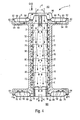
- the turbine blade 1 according to FIG. 1 has an airfoil 2, which extends along a blade axis 4.
- the Blade 2 is suitable for influencing a working fluid flowing in an associated turbine unit arched and / or curved.
- the turbine blade 1 is as a guide blade for one here Gas turbine not shown and in the manner of a closed Cooling as coolable with cooling air as cooling medium Turbine blade designed.
- an inflow channel 6 in the cooling medium K of the Coolant inflow side AS can come forth, and an outflow channel 8 out for cooling medium K. Via the outflow channel 8, the cooling medium can the airfoil 2 on the cooling medium outflow side Leave BS again.
- the inflow channel 6 is on the one hand by a flat, closed wall 10 which is diagonal runs in the airfoil 2, and on the other hand through a flat, outlet openings 12 for cooling medium K Wall 14 limited; the closed wall 10 and the outlet openings 12 wall 14 can be made of sheet metal be formed.
- wall 14 is parallel to one to be cooled Inner wall 16 of the airfoil 2 arranged, see above that between this inner wall 16 and the aforementioned wall 14th of the inflow channel 6, an overflow channel 18 is formed.
- the outflow channel 8 is limited on the one hand from the flat, closed wall 10 which diagonally in the airfoil 2 and the inflow channel 6 of the Outflow channel 8 separates, and on the other hand from an inner wall 22 of the airfoil 2, that of the inner wall to be cooled 16 is opposite.
- the arrangement is chosen such that the free cross section 40 of the inflow channel 6 in the airfoil 2 in its longitudinal direction L decreases linearly. At the same time increases with the measure this decrease, the free cross section 52 of the outflow channel 8 in the airfoil 2 in its longitudinal direction L. Moreover both the inflow channel 6 and the outflow channel 8 are parallel to the longitudinal direction L of the airfoil 2 and perpendicular a triangular cross-section to the inner wall 16 to be cooled on.
- the overflow of the cooling medium K from the inflow channel 6 in the outflow channel 8 illustrates Figure 2, the a cross section along line II - II through the turbine blade 1 according to FIG. 1.
- the inflow channel 6 has a closed wall 10 two more connecting the latter walls 10, 14 Walls 24, 26 so that the inflow channel 6 with the exception of one Entry surface and the outlet openings 12 closed is.
- the other walls 24, 26 can each of a sheet metal plate are formed.
- cooling medium K leaves this channel on the Outlet openings 12 and then hits the inner wall 16 of the airfoil 2.
- This results in an impact cooling effect which is further reinforced by the fact that the cooling medium K - additionally guided by ribs 20 - on the inner wall 16 of the airfoil 2 in its transverse direction Q is guided along and through overflow channels 18, 28, 30 reaches the outflow channel 8; the cooling medium flows K around at least part of the inflow channel 6 and arrives then in the discharge channel 8, through which it in turn Longitudinal direction of the airfoil 2 flows off. Because of the the inner wall 16 of the airfoil 2 arranged ribs 20 results in a cooling fin effect which increases the cooling effect.
- FIG. 1 Another turbine blade 1 with an airfoil 2 3 shows a partially cut, perspective view.
- the airfoil 2 has a first and a second here Inflow channel 6, 32 for cooling medium K, the inflow channels 6, 32 based on the blade axis 4 symmetrical to each other are arranged and the airfoil 2 in its Pull lengthwise L over a length of 1.
- Cooling medium K occurs on the coolant inflow side AS of the airfoil 2 into the inflow channels 6, 32, flows through the airfoil 2 in its longitudinal direction L in both inflow channels 6, 32 and leaves it via outlet openings 12, which are shown in FIG for the sake of clarity, only in the first inflow channel 6 are shown.
- the cooling medium K then flows in one perpendicular to the longitudinal direction L of the airfoil 2 Transverse direction Q each on an inner wall to be cooled 16, 36 of the airfoil 2 along.
- These inner walls 16, 36 are the outlet openings 12 of the inflow channels 6, 32 arranged opposite and with - in Figure 3 the For the sake of clarity, only on the first inner wall to be cooled 16 shown - ribs 20 for guiding the cooling medium K provided.
- the flow along the inner walls to be cooled 16, 36 takes place during a transfer of the cooling medium K from the inflow channels 6, 32 into a common outflow channel 8 for cooling medium K, the middle between the inflow channels 6, 32 is arranged. Via the discharge channel 8 becomes the cooling medium K in the longitudinal direction L of the airfoil 2 fed to the cooling medium outflow side BS.
- the inflow channels 6, 32 each have an entry surface 34, 38 forming free cross-section of the same size.
- This free cross section of the inflow channels 6, 32 takes in the airfoil 2 linearly in its longitudinal direction L, so that at half length 1/2 the free cross section 40, 42 each also is halved when the inflow channels 6, 32 at their Entry surface 34, 38 for end 44 facing away from cooling medium K, 46 do not have a free cross section. That means at the same time that the inflow channels at this end 44, 46 are closed.
- the outflow channel 8 is at one of one free cross section formed outlet surface 48 for cooling medium K sealed at the beginning 50 and has no there free cross section.
- the free cross section of the outflow channel 8 in the airfoil 2 takes in its longitudinal direction L corresponding to the decrease in the free cross section of the Inflow channels 6, 32 too. Therefore, the free cross section 52 of the outflow channel 8 at half the length 1/2 of the airfoil 2 an area corresponding to the sum of the free cross sections 40, 42 of the inflow channels 6, 32 corresponds at this point. In order to free flow of the cooling medium K is guaranteed.
- the airfoil 2 In addition to a recess 54 running in the longitudinal direction L, in which arranged the inflow channels 6, 32 and the outflow channel 8 are, the airfoil 2 further in the longitudinal direction L extending recesses 56, 58, 60.
- the latter Recesses 56, 58, 60, shown as cavities in Figure 3 are also available with appropriate inflow and outflow channels be provided for cooling medium and for cooling the turbine blade 1 can be used.
- FIG. 1 Another turbine blade 1, in particular a guide blade can be for a gas turbine, with a two respect a blade axis 4 symmetrically arranged inflow channels 6, 32 for airfoil 2 having cooling medium K.
- Figure 4 in a longitudinal section.
- To the airfoil 2 is on a cooling medium inflow side AS a cross to the Shaped first platform 62 extending blade axis 4, which forms a head plate.
- On a coolant outflow side BS is a transverse to the blade axis 4, a second platform 64 forming a base plate is formed.
- cooling medium K occurs in the first on the coolant inflow side AS Platform 62 and in a shielded by a cover plate 66 central, connected to the inflow channels 6, 32 Area of the airfoil 2.
- a cooling chamber 68 of the first Platform 62 is connected to the outflow channel 8, so that already used for cooling the first platform 62 Cooling medium K through the outflow channel 8 directly can be led out of the airfoil 2.
- the cooling medium K supplied to the inflow channels 6, 32 leaves these inflow channels 6, 32 either through outlet openings 12, 70 in inner walls 16, 36 of the airfoil to be cooled 2 facing walls 14, 72 or by on the respective Entry surface for cooling medium K facing away from the Inflow channels 6, 32 provided transitions 74, 76 to one Cooling chamber 78 of the second platform 64.
- the cooling medium K, the through the outlet openings 12, 70 is in a transverse direction Q on the ribs 20, 80 to be cooled Inner walls 16, 36 of the airfoil 2 along out, then enters and leaves the outflow channel 8 via this the airfoil 2 on its cooling medium outflow side BS.
- the cooling chambers 68, 78 of the platforms 62, 64 are in these cast in and outwards through a cover plate 82, 84 completed.
- the cooling chambers 68, 78 each in its bottom area with a spacing from the chamber bottom 86, 88 arranged baffle cooling plate 90, 92 provided.
- An outflow space is in the cooling chamber 68 of the first platform 62 94 available through the chamber floor 86 and Baffle cooling plate 90 is limited and connected to the outflow channel 8 is.
- the cooling chamber 78 faces the second Platform 64 has an inflow space 96 through the cover plate 84 and the baffle plate 92 is limited and to the Inflow channels 6, 32 is connected. That way the inflow space 96 is fed by the inflow channels 6, 32, which are separated from the outflow channel 8 by walls 10, 98 are.
Abstract
Description
Die Erfindung bezieht sich auf eine Turbinenschaufel mit einem sich entlang einer Schaufelachse erstreckenden, hauptsächlich in seiner Längsrichtung von einem Kühlmedium durchströmbaren Schaufelblatt.The invention relates to a turbine blade with a extending along a blade axis, mainly in its longitudinal direction through which a cooling medium can flow Airfoil.
Gasturbinen werden in vielen Bereichen zum Antrieb von Generatoren oder von Arbeitsmaschinen eingesetzt. Dabei wird der Energieinhalt eines Brennstoffs zur Erzeugung einer Rotationsbewegung einer Turbinenwelle benutzt. Der Brennstoff wird dazu in einer Brennkammer verbrannt, wobei von einem Luftverdichter verdichtete Luft zugeführt wird. Das in der Brennkammer durch die Verbrennung des Brennstoffs erzeugte, unter hohem Druck und unter hoher Temperatur stehende Arbeitsmedium wird dabei über eine der Brennkammer nachgeschaltete Turbineneinheit geführt, wo es sich arbeitsleistend entspannt.Gas turbines are used to drive generators in many areas or used by work machines. The Energy content of a fuel to generate a rotational movement a turbine shaft used. The fuel will To do this, burned in a combustion chamber, using an air compressor compressed air is supplied. That in the combustion chamber generated by the combustion of the fuel, under high Pressure and high temperature working medium is via a turbine unit downstream of the combustion chamber managed where it relaxes while working.
Zur Erzeugung der Rotationsbewegung der Turbinenwelle sind dabei an dieser eine Anzahl von üblicherweise in Schaufelgruppen oder Schaufelreihen zusammengefaßten Laufschaufeln angeordnet, die über einen Impulsübertrag aus dem Strömungsmedium die Turbinenwelle antreiben. Zur Führung des Strömungsmediums in der Turbineneinheit sind zudem üblicherweise zwischen benachbarten Laufschaufelreihen mit dem Turbinengehäuse verbundene Leitschaufelreihen angeordnet. Die Turbinenschaufeln, insbesondere die Leitschaufeln, weisen dabei üblicherweise zur geeigneten Führung des Arbeitsmediums ein entlang einer Schaufelachse erstrecktes Schaufelblatt auf, an das endseitig zur Befestigung der Turbinenschaufel am jeweiligen Trägerkörper eine sich quer zur Schaufelachse erstrekkende Plattform angeformt sein kann.To generate the rotational movement of the turbine shaft are a number of them usually in groups of blades or rows of blades grouped together arranged via a pulse transfer from the flow medium drive the turbine shaft. For guiding the flow medium are also common in the turbine unit between adjacent rows of blades with the turbine housing connected rows of vanes arranged. The turbine blades, in particular, the guide vanes usually have for appropriate guidance of the working medium along of an airfoil extending blade on the end for fastening the turbine blade to the respective Carrier body extending transversely to the blade axis Platform can be molded.
Bei der Auslegung derartiger Gasturbinen ist zusätzlich zur erreichbaren Leistung üblicherweise ein besonders hoher Wirkungsgrad ein Auslegungsziel. Eine Erhöhung des Wirkungsgrades läßt sich dabei aus thermodynamischen Gründen grundsätzlich durch eine Erhöhung der Austrittstemperatur erreichen, mit dem das Arbeitsmedium aus der Brennkammer ab- und in die Turbineneinheit einströmt. Daher werden Temperaturen von etwa 1200 °C bis 1300 °C für derartige Gasturbinen angestrebt und auch erreicht.When designing such gas turbines in addition to achievable performance usually a particularly high efficiency a design goal. An increase in efficiency can basically be done for thermodynamic reasons by increasing the outlet temperature, with which the working medium from the combustion chamber and into the Turbine unit flows. Therefore temperatures of around Desired 1200 ° C to 1300 ° C for such gas turbines and also achieved.
Bei derartig hohen Temperaturen des Arbeitsmediums sind jedoch die diesem ausgesetzten Komponenten und Bauteile hohen thermischen Belastungen ausgesetzt. Um dennoch bei hoher Zuverlässigkeit eine vergleichsweise lange Lebensdauer der betroffenen Komponenten zu gewährleisten, ist üblicherweise eine Kühlung der betroffenen Komponenten, insbesondere von Lauf- und/oder Leitschaufeln der Turbineneinheit, vorgesehen. Die Turbinenschaufeln sind daher üblicherweise kühlbar ausgebildet, wobei insbesondere eine wirksame und zuverlässige Kühlung der in Strömungsrichtung des Arbeitsmediums gesehen ersten Schaufelreihen sichergestellt sein soll. Zur Kühlung weist die jeweilige Turbinenschaufel dabei üblicherweise einen in das Schaufelblatt oder das Schaufelprofil integrierten Kühlmediumkanal auf, von dem aus ein Kühlmedium gezielt insbesondere den thermisch belasteten Zonen der Turbinenschaufel zuleitbar ist.At such high temperatures of the working medium, however the high components and parts exposed to it exposed to thermal loads. To still with high reliability a comparatively long lifespan for those affected Ensuring components is usually one Cooling of the affected components, especially of Rotor and / or guide vanes of the turbine unit are provided. The turbine blades are therefore usually designed to be coolable, being particularly effective and reliable Cooling seen in the flow direction of the working medium first rows of blades should be ensured. For cooling the respective turbine blade usually has one integrated into the airfoil or the airfoil Cooling medium channel from which a cooling medium in particular targeted the thermally stressed zones of the turbine blade is feedable.
Als Kühlmedium kommt dabei üblicherweise Kühlluft zum Einsatz. Diese wird der jeweiligen Turbinenschaufel üblicherweise in der Art einer offenen Kühlung über einen integrierten Kühlmediumkanal zugeführt. Nach dem Austritt aus der Turbinenschaufel wird die Kühlluft dabei mit dem in der Turbineneinheit geführten Arbeitsmedium vermischt. Die Auslegungsleistung einer derartig gekühlten Gasturbine ist jedoch begrenzt, insbesondere da im Hinblick auf die begrenzte mechanische Belastbarkeit einzelner Komponenten der Gasturbine eine weitere Leistungssteigerung üblicherweise nur durch eine vermehrte Brennstoffzufuhr erreichbar ist. Diese bedingt ihrerseits einen vergleichsweise erhöhten Bedarf an Kühlmedium zur Kühlung der Turbinenschaufeln, der seinerseits Verluste im verfügbaren Verdichtermassenstrom bedeutet. Diese Verluste können wiederum nur in begrenztem Ausmaß hingenommen werden. Außerdem kann es in Gasturbinen auch im Hinblick auf eine erforderliche Sicherheit notwendig sein, eine Vermischung von aus der Turbinenschaufel abströmendem Kühlmedium und die Turbineneinheit durchströmendem Arbeitsmedium zu verhindern.Cooling air is usually used as the cooling medium. This is usually the case for the respective turbine blade in the manner of open cooling via an integrated one Coolant channel supplied. After exiting the turbine blade the cooling air is combined with that in the turbine unit led working medium mixed. The design performance a gas turbine cooled in this way is however limited, especially since in terms of limited mechanical Resilience of individual components of the gas turbine further increase in performance usually only by one increased fuel supply is achievable. This in turn requires a comparatively increased need for cooling medium to cool the turbine blades, which in turn losses in the available compressor mass flow means. These losses can only be accepted to a limited extent. It can also be required in gas turbines also with regard to Security may need to be mixed coolant flowing out of the turbine blade and the turbine unit to prevent working medium flowing through.
Der Erfindung liegt daher die Aufgabe zugrunde, eine Turbinenschaufel der oben genannten Art anzugeben, für die mit vergleichsweise einfachen Mitteln eine zuverlässige und wirkungsvolle geschlossene Kühlung, insbesondere unter Verwendung von Kühlluft als Kühlmedium, ermöglicht ist.The invention is therefore based on the object of a turbine blade of the type mentioned above for which with comparatively simple means a reliable and effective closed cooling, especially using of cooling air as a cooling medium.
Diese Aufgabe wird erfindungsgemäß gelöst, indem im Schaufelblatt im wesentlichen über seine gesamte Länge ein Anströmund ein Abströmkanal für Kühlmedium geführt sind und der Anström- und der Abströmkanal kühlmediumseitig derart miteinander verbunden sind, daß von dem Anström- in den Abströmkanal übertretendes Kühlmedium in einer Querrtchtung an einer zu kühlenden Innenwandung des Schaufelblattes entlang geführt ist.This object is achieved in that in the airfoil essentially an inflow over its entire length an outflow channel for cooling medium and the inflow and the outflow channel on the cooling medium side with one another in this way are connected that from the inflow into the outflow channel Excess cooling medium in a cross direction on one cooling along the inner wall of the airfoil is.
Die Erfindung geht dabei von der Überlegung aus, daß eine wirkungsvolle Kühlung für eine Turbinenschaufel insbesondere mit einer flächigen Beaufschlagung der zu kühlenden Wandung des Schaufelblattes mit Kühlmedium zu erzielen ist. Es wurde erkannt, daß eine solche flächige Beaufschlagung einer gezielten Zuführung des Kühlmediums zu der Wandung und einer Führung des Kühlmediums an dieser entlang bedarf. Dieses ist erreichbar, indem jeweils ein separater Anström- und Abströmkanal für Kühlmedium vorgesehen ist. Ausgehend von dieser Zweiteilung des Kühlmediumkanals erfolgt die Beaufschlagung der zu kühlenden Wandung des Schaufelblattes in der Weise, daß das Kühlmedium im Verlauf seines Übertritts von dem Anström- in den Abströmkanal in einer Querrichtung geführt wird. The invention is based on the consideration that a effective cooling for a turbine blade in particular with a flat application of the wall to be cooled of the airfoil can be achieved with cooling medium. It was recognized that such a flat application of a targeted Supply of the cooling medium to the wall and one Guidance of the cooling medium along this needs. This is achievable by a separate inflow and outflow channel is provided for cooling medium. Starting from this The cooling medium channel is divided into two the wall of the airfoil to be cooled in such a way that the cooling medium in the course of its transfer from the inflow led in the outflow channel in a transverse direction becomes.
Die Führung des Kühlmediums hauptsächlich in der Längsrichtung des Schaufelblattes ermöglicht die Einhaltung besonders kurzer und somit verlustverminderter Strömungswege für den Kühlmediumstrom. Diese hauptsächliche Strömungsrichtung wird nur in dem Bereich in eine Querrichtung geändert, in dem eine solche Änderung der gezielten und effektiven Kühlung dient. Unvermeidliche Strömungsverluste werden so auf niedrigem Niveau gehalten. Auch eine Beaufschlagung des Schaufelblattes mit einer vergleichsweise großen Menge an Kühlmedium ist nicht durch Einschränkungen im Strömungsweg behindert. Von besonderem Vorteil ist, daß eine große Kühlleistung in einem vergleichsweise geringen Abschnitt des Strömungsweges des Kühlmediums, nämlich im Verlauf seines in der Querrichtung zum Schaufelblatt angeordneten Wegabschnitts, beim Übertritt von dem Anström- in den Abströmkanal gezielt erbracht wird.The cooling medium is guided mainly in the longitudinal direction of the airfoil enables compliance in particular short and thus loss-reduced flow paths for the Coolant flow. This main flow direction is changed only in a transverse direction in the area where a such change serves the targeted and effective cooling. Inevitable flow losses are at a low level held. Also an action on the airfoil with a comparatively large amount of cooling medium not hindered by restrictions in the flow path. Of A particular advantage is that a large cooling capacity in one comparatively small section of the flow path of the Cooling medium, namely in the course of it in the transverse direction path section arranged to the airfoil, at the crossing from the inflow into the outflow channel.
Der Anströmkanal kann an ausgewählten, thermisch besonders hoch belasteten Bereichen der Turbinenschaufel zugeordneten Stellen Austrittsöffnungen für Kühlmedium zum Übertritt in den Abströmkanal aufweisen. Von besonderem Vorteil ist es aber, wenn der Anströmkanal in etwa gleichmäßig über seine Länge verteilt der zu kühlenden Innenwandung des Schaufelblattes zugewandte Austrittsöffnungen für das Kühlmedium aufweist. Auf diese Weise ist besonders einfach eine flächige Kühlung des Schaufelblattes erzielbar. Die Kühlung kann dabei mittels einer sogenannten Prallkühlung erfolgen, wobei eine die Austrittsöffnungen aufweisende Wand des Anströmkanals als Prallkühlwand dient, mit der auf sie auftreffendes Kühlmedium in intensiven Kontakt tritt und anschließend über die Austrittsöffnungen zum Übertritt in den Abströmkanal abgeleitet werden kann.The inflow channel can be selected, particularly thermal assigned to highly stressed areas of the turbine blade Provide outlet openings for coolant to pass into have the outflow channel. It is particularly advantageous but when the inflow channel is roughly even over its Length distributes the inner wall of the airfoil to be cooled has facing outlet openings for the cooling medium. In this way, a flat is particularly simple Cooling of the airfoil achievable. The cooling can by means of a so-called impingement cooling, one the wall of the inflow channel having outlet openings as Baffle cooling wall serves with the cooling medium impinging on it comes into intensive contact and then through the outlet openings derived for crossing into the outflow channel can be.
Um ein gleichmäßiges Strömen des Kühlmediums zu gewährleisten und den in der Turbinenschaufel zur Verfügung stehenden Raum möglichst gezielt auszunutzen, nimmt der freie Querschnitt des Anströmkanals im Schaufelblatt in dessen Längsrichtung vorzugsweise ab. Somit wird dem Umstand Rechnung getragen, daß im Verlauf des Anströmkanals ein zunehmender Teil des Kühlmediums den Anströmkanal bereits verlassen hat und in den Abströmkanal übergetreten ist. Insbesondere bei einer über die Länge des Schaufelblattes gleichmäßigen, flächigen Beaufschlagung mit Kühlmedium ist es für eine einfache Bauausführung der Turbinenschaufel besonders vorteilhaft, wenn der freie Querschnitt des Anströmkanals im Schaufelblatt in dessen Längsrichtung linear abnimmt. In diesem Fall kann der Anströmkanal beispielsweise sehr einfach aus ebenen Blechplatten gebildet sein. Im Interesse eines gleichmäßigen, freien Volumenstroms von Kühlmedium durch die Turbinenschaufel hindurch nimmt der freie Querschnitt des Abströmkanals im Schaufelblatt in dessen Längsrichtung entsprechend der Abnahme des freien Querschnitts des Anströmkanals zu. In dem Umfang, in dem Kühlmedium den Anströmkanal verläßt, wird der freie Querschnitt des Anströmkanals verkleinert und gleichzeitig in entsprechendem Maß der freie Querschnitt des Abströmkanals für abfließendes Kühlmedium vergrößert. Dadurch kann das im Verlauf des Abströmkanals zusätzlich in diesen übertretende Kühlmedium ohne Hindernis zügig abgeführt werden.To ensure an even flow of the cooling medium and the space available in the turbine blade the free cross-section takes advantage of as specifically as possible of the inflow channel in the airfoil in its longitudinal direction preferably from. This takes account of the fact that an increasing part of the Cooling medium has already left the inflow channel and into the Outflow channel is exceeded. Especially with an over the length of the airfoil even, flat exposure with cooling medium it is for simple construction the turbine blade is particularly advantageous if the free cross section of the inflow channel in the airfoil in its The linear direction decreases linearly. In this case, the inflow channel for example very simply from flat sheet metal plates be educated. In the interest of an even, free Volume flow of cooling medium through the turbine blade takes the free cross-section of the outflow channel in the airfoil in its longitudinal direction according to the decrease in free cross-section of the inflow channel. To the extent in the cooling medium leaves the inflow channel, the free cross section of the inflow channel reduced and at the same time in the free cross-section of the outflow channel correspondingly enlarged for draining cooling medium. This can in Course of the outflow channel additionally crossing into this Coolant can be removed quickly without obstacles.
Ein sehr einfacher Aufbau von Anström- und/oder Abströmkanal beispielsweise aus ebenen Platten ergibt sich, wenn der Anströmkanal und/oder der Abströmkanal parallel zur Längsrichtung des Schaufelblattes und senkrecht zu der zu kühlenden Innenwandung des Schaufelblattes gemäß einer vorteilhaften Weiterbildung einen dreieckigen Querschnitt aufweist.A very simple construction of the inflow and / or outflow channel for example from flat plates arises when the inflow channel and / or the outflow channel parallel to the longitudinal direction of the airfoil and perpendicular to the one to be cooled Inner wall of the airfoil according to an advantageous Training has a triangular cross section.
Da üblicherweise nicht alle Wandungen des Schaufelblattes der Turbinenschaufel gleichen thermischen Belastungen ausgesetzt sind, kann es hinreichend sein, nur einen Anströmkanal zur Kühlung einer thermisch besonders stark beanspruchten Wandung in der Turbinenschaufel vorzusehen. Insbesondere jedoch wenn sowohl die Druck- als auch die Saugseite der Turbinenschaufel gekühlt werden muß, ist es von Vorteil, einen zweiten Anströmkanal für Kühlmedium zur Kühlung einer weiteren Innenwandung des Schaufelblattes vorzusehen, der bezogen auf die Schaufelachse symmetrisch zu dem ersten Anströmkanal angeordnet ist. Da dabei die zu kühlenden Innenwandungen gegenüberliegend angeordnet sind, münden der erste und der zweite Anströmkanal vorzugsweise in einen gemeinsamen Abströmkanal für Kühlmedium. Der Abströmkanal kann beispielsweise günstig in einem zentralen Bereich des Schaufelblattes verlaufen.Since usually not all walls of the airfoil Turbine blade exposed to the same thermal loads , it may be sufficient to use only one inflow channel Cooling a thermally particularly stressed wall to be provided in the turbine blade. But especially if both the pressure and the suction side of the turbine blade must be cooled, it is advantageous to have a second inflow channel for cooling medium for cooling another inner wall to provide the airfoil, based on the Blade axis arranged symmetrically to the first inflow channel is. Because the inner walls to be cooled are opposite are arranged, the first and the second inflow channel open preferably in a common outflow channel for Cooling medium. The outflow channel can, for example, be inexpensive in run a central area of the airfoil.
Das Entlangführen des Kühlmediums an der zu kühlenden Innewandung des Schaufelblattes in dessen Querrichtung erfolgt noch zielgerichteter und die Kühlwirkung verstärkend, wenn gemäß einer anderen vorteilhaften Weiterbildung die oder - bei mehreren zu kühlenden Innenwandungen - jede zu kühlende Innenwandung des Schaufelblattes jeweils mit das Kühlmedium leitenden, quer zur Schaufelachse angeordneten Rippen versehen ist. Diese Rippen haben außerdem einen zusätzlichen Kühlrippeneffekt zur Folge und verbessern somit die Kühlung weiter.The cooling medium is guided along the inner wall to be cooled of the airfoil in its transverse direction even more targeted and reinforcing the cooling effect when according to another advantageous development, the or with several inner walls to be cooled - each to be cooled Inner wall of the airfoil with the cooling medium conductive ribs arranged transversely to the blade axis is. These fins also have an additional cooling fin effect result and thus further improve the cooling.
Vorzugsweise ist der Anströmkanal an seinem einer Eintrittsfläche für Kühlmedium abgewandten Ende und/oder der Abströmkanal an seinem einer Austrittsfläche für Kühlmedium abgewandten Anfang verschlossen, wodurch ein einfacher Aufbau und eine störungsfreie An- und Abführung des Kühlmediums zu der und von der Turbinenschaufel ermöglicht wird.The inflow channel is preferably at its one entry surface for the end facing away from the cooling medium and / or the outflow channel on its an outlet surface facing away from the cooling medium Locked at the beginning, making it easy to set up and a trouble-free supply and discharge of the cooling medium to the and made possible by the turbine blade.
Beispielsweise bei eine sich quer zu der Schaufelachse erstreckende Plattform - insbesondere zum Anschluß der Turbinenschaufeln an ein Turbinengehäuse - aufweisenden Turbinenschaufeln, bei denen aufgrund hoher thermischer Beanspruchung auch eine Kühlung der Plattform gewünscht ist, kann es jedoch günstig sein, von dem vorbeschriebenen Bauprinzip abzuweichen: Von Vorteil ist eine Turbinenschaufel, bei der an das Schaufelblatt an dessen Kühlmediumabströmseite eine sich quer zur Schaufelachse erstreckende Plattform angeformt ist, wenn die Plattform eine an den Anströmkanal angeschlossene, mit Kühlmedium beaufschlagbare Kühlkammer aufweist. Auf diese Weise wird der Anströmkanal, der Kühlmedium der zu kühlenden Innenwandung des Schaufelblattes zuführt, die Bauform der Turbinenschaufel erheblich vereinfachend gleichzeitig als Zuführkanal von Kühlmedium zu der Kühlkammer der Plattform verwendet. - Von ebensolchem Vorteil ist eine Turbinenschaufel, bei der an das Schaufelblatt an dessen Kühlmediumanströmseite eine sich quer zur Schaufelachse erstreckende Plattform angeformt ist, die eine an den Abströmkanal angeschlossene, mit Kühlmedium beaufschlagbare Kühlkammer aufweist. Dabei kann das zur Kühlung der Plattform herangezogene Kühlmedium unmittelbar aus dem Schaufelblatt abgeführt werden, ohne daß aufwendige Rückströmkanäle vorgesehen werden müßten oder daß die Gefahr der Vermischung mit Kühlmedium bestehen könnte, das zur Kühlung der Innenwandung des Schaufelblattes vorgesehen ist. Die wirkungsvolle Kühlung des Schaufelblattes ist somit nicht gefährdet.For example, one that extends transversely to the blade axis Platform - especially for connecting the turbine blades to a turbine housing - having turbine blades, where due to high thermal stress cooling of the platform is also desired, however be favorable to deviate from the construction principle described above: A turbine blade, in which the Airfoil on its coolant outflow side a cross to the blade axis extending platform is formed if the platform is connected to the inflow channel Has cooling medium acted upon cooling chamber. To this The inflow channel, the cooling medium of the one to be cooled, becomes wise Inner wall of the airfoil feeds the design of the Turbine blade considerably simplifying at the same time as a feed channel of cooling medium used to the cooling chamber of the platform. - A turbine blade is just as advantageous, on the airfoil on its cooling medium inflow side a platform is formed which extends transversely to the blade axis is the one connected to the outflow channel with Has cooling medium acted upon cooling chamber. It can the cooling medium used to cool the platform immediately can be discharged from the airfoil without expensive Return flow channels would have to be provided or that the There could be a risk of mixing with the cooling medium provided for cooling the inner wall of the airfoil is. The effective cooling of the airfoil is thus not endangered.
Für einen besonders geringen Aufwand bei der Herstellung der Turbinenschaufel ist die oder jede Kühlkammer vorteilhafterweise in die jeweilige Plattform eingegossen und nach außen über ein Abdeckblech abgeschlossen. Somit kann die Kühlkammer direkt beim Gießen der Turbinenschaufel mithergestellt werden, so daß eine Nachbearbeitung des Gußkörpers nicht erforderlich ist. Zum zuverlässigen Abschluß der jeweiligen Kühlkammer nach außen ist dabei lediglich die Anbringung des jeweiligen Abdeckblechs erforderlich.For a particularly low cost in the manufacture of the The turbine blade is advantageously the or each cooling chamber poured into the respective platform and to the outside completed with a cover plate. Thus the cooling chamber are produced directly when the turbine blade is cast, so that post-processing of the cast body is not necessary is. For the reliable closure of the respective cooling chamber to the outside is only the attachment of the respective Cover plate required.
Eine besonders zuverlässige Kühlung der jeweiligen Strukturteile mit Kühlmedium ist mittels einer Prallkühlung erreichbar. Dazu ist die oder jede Kühlkammer vorteilhaft in einem Bodenbereich mit einem beabstandet zum Kammerboden angeordneten Prallkühlblech versehen. Das Prallkühlblech ist dabei im wesentlichen als gelochtes Blech ausgebildet, wobei auf das Prallkühlblech auftreffendes Kühlmedium mit diesem in besonders intensiven Kontakt tritt und anschließend über die Lochung abgeleitet werden kann. Für eine zuverlässige Kühlmediumableitung ist dabei in weiterer vorteilhafter Ausgestaltung ein durch den Kammerboden und das Prallkühlblech begrenzter Abströmraum der Kühlkammer an den Abströmkanal angeschlossen. Entsprechend ist für eine zuverlässige Zuleitung von Kühlmedium zu der Kühlkammer gemäß einer anderen vorteilhaften Weiterbildung ein durch das Abdeckblech und das Prallkühlblech begrenzter Anströmraum der Kühlkammer an den Anströmkanal angeschlossen.A particularly reliable cooling of the respective structural parts with cooling medium can be reached by means of impingement cooling. For this purpose, the or each cooling chamber is advantageous in one Floor area with a spaced from the chamber floor Provide baffle plate. The baffle plate is in the essentially formed as a perforated sheet, with the Impingement cooling plate impinging cooling medium with this in particular intensive contact occurs and then over the perforation can be derived. For reliable coolant drainage is in a further advantageous embodiment one limited by the chamber floor and the baffle cooling plate Outflow chamber of the cooling chamber connected to the outflow channel. Corresponding is for a reliable supply of cooling medium to the cooling chamber according to another advantageous development one through the cover plate and the baffle cooling plate limited flow chamber of the cooling chamber connected to the flow channel.
Die Turbinenschaufel ist vorzugsweise als Leitschaufel für eine Gasturbine, insbesondere für eine stationäre Gasturbine, ausgebildet.The turbine blade is preferably used as a guide blade for a gas turbine, especially for a stationary gas turbine, educated.
Die mit der Erfindung erzielten Vorteile bestehen insbesondere darin, daß durch das Vorsehen eines Anström- und eines Abströmkanals in der Turbinenschaufel das Kühlmedium beim Übertritt von dem Anström- in den Abströmkanal in einer Querrichtung innen an dem Schaufelblatt entlang geführt wird, wodurch eine flächige Beaufschlagung des Schaufelblattes ermöglicht ist und sich eine besonders effektive Kühlung ergibt. Die Turbinenschaufel ist dabei mit vergleichsweise geringem Aufwand herstellbar, wobei insbesondere von Bedeutung ist, daß An- und Abströmkanal als einfache Einsätze, die in dem Schaufelblatt montierbar sind, ausgebildet sein können. Zudem ist auf vergleichsweise einfache Weise eine Einbeziehung von Konzepten einer geschlossenen Kühlung mit Luft als Kühlmedium ermöglicht.The advantages achieved with the invention are in particular in that by providing an inflow and an outflow channel the coolant in the turbine blade when it passes from the inflow into the outflow channel in a transverse direction is guided along the inside of the airfoil, whereby a flat application of the airfoil enables is and there is a particularly effective cooling. The Turbine blade is comparatively easy producible, it being particularly important that Inflow and outflow channel as simple inserts in the airfoil are mountable, can be designed. In addition is incorporating concepts in a comparatively simple way closed cooling with air as the cooling medium allows.
Ein Ausführungsbeispiel der Erfindung wird anhand einer Zeichnung näher erläutert. Darin zeigen:
Figur 1- eine Turbinenschaufel in einem Teil-Längsschnitt,
Figur 2- einen Querschnitt durch die
Turbinenschaufel nach Figur 1, - Figur 3
- eine andere Turbinenschaufel in teilgeschnittener perspektivischer Ansicht und
- Figur 4
- eine weitere Turbinenschaufel in einem Längsschnitt.
- Figure 1
- a turbine blade in a partial longitudinal section,
- Figure 2
- 2 shows a cross section through the turbine blade according to FIG. 1,
- Figure 3
- another turbine blade in a partially cut perspective view and
- Figure 4
- another turbine blade in a longitudinal section.
Gleiche Teile sind in allen Figuren mit denselben Bezugszeichen versehen.The same parts have the same reference symbols in all the figures Mistake.
Die Turbinenschaufel 1 gemäß Figur 1 weist ein Schaufelblatt
2 auf, das sich entlang einer Schaufelachse 4 erstreckt. Das
Schaufelblatt 2 ist dabei zur geeigneten Beeinflussung eines
in einer zugeordneten Turbineneinheit strömenden Arbeitsmediums
gewölbt und/oder gekrümmt.The
Die Turbinenschaufel 1 ist als Leitschaufel für eine hier
nicht weiter dargestellte Gasturbine und in der Art einer geschlossenen
Kühlung als mit Kühlluft als Kühlmedium kühlbare
Turbinenschaufel ausgebildet. Dazu ist das Schaufelblatt 2
hauptsächlich in seiner Längsrichtung L von Kühlmedium K
durchströmbar, wobei das Kühlmedium K von einer Kühlmediumanströmseite
AS her in das Schaufelblatt 2 eintritt und an einer
Kühlmediumabströmseite BS aus diesem wieder hinaustritt.The
In dem Schaufelblatt 2 sind im wesentlichen über dessen gesamte
Länge 1 ein Anströmkanal 6, in den Kühlmedium K von der
Kühlmediumanströmseite AS her eintreten kann, und ein Abströmkanal
8 für Kühlmedium K geführt. Über den Abströmkanal
8 kann das Kühlmedium das Schaufelblatt 2 an der Kühlmediumabströmseite
BS wieder verlassen. Der Anströmkanal 6 wird
einerseits durch eine ebene, geschlossene Wand 10, die diagonal
in dem Schaufelblatt 2 verläuft, und andererseits durch
eine ebene, Austrittsöffnungen 12 für Kühlmedium K aufweisende
Wand 14 begrenzt; die geschlossene Wand 10 und die Austrittsöffnungen
12 aufweisende Wand 14 können von Blechplatten
gebildet werden. Die die Austrittsöffnungen 12, die in
etwa gleichmäßig über die Länge 1 des Anströmkanals 6 verteilt
sind, aufweisende Wand 14 ist parallel zu einer zu kühlenden
Innenwandung 16 des Schaufelblattes 2 angeordnet, so
daß zwischen dieser Innenwandung 16 und vorgenannter Wand 14
des Anströmkanals 6 ein Überströmkanal 18 ausgebildet ist.In the
In dem Überströmkanal 18 wird von dem Anströmkanal 6 in den
Abströmkanal 8 übertretendes Kühlmedium K in einer Querrichtung
Q des Schaufelblattes 2 an der zu kühlenden Innenwandung
16 des Schaufelblattes 2 entlang geführt. An dieser Innenwandung
16 sind in Querrichtung Q des Schaufelblattes 2 verlaufende
Rippen 20 angeordnet, die die Strömungsrichtung des
übertretenden Kühlmediums K mitbestimmen und außerdem zusätzlich
als Kühlrippen für das Schaufelblatt 2 dienen.In the
Nachdem das Kühlmedium an der Innenwandung 16 des Schaufelblattes
2 diese kühlend entlang geströmt ist, tritt es in den
Abströmkanal 8 ein. Der Abströmkanal 8 wird einerseits begrenzt
von der ebenen, geschlossenen Wand 10, die diagonal in
dem Schaufelblatt 2 verläuft und den Anströmkanal 6 von dem
Abströmkanal 8 trennt, und andererseits von einer Innenwandung
22 des Schaufelblattes 2, die der zu kühlenden Innenwandung
16 gegenüberliegt.After the cooling medium on the
Die Anordnung ist derart gewählt, daß der freie Querschnitt
40 des Anströmkanals 6 im Schaufelblatt 2 in dessen Längsrichtung
L linear abnimmt. Gleichzeitig nimmt mit dem Maß
dieser Abnahme der freie Querschnitt 52 des Abströmkanals 8
im Schaufelblatt 2 in dessen Längsrichtung L zu. Außerdem
weisen sowohl der Anström- 6 als auch der Abströmkanal 8 parallel
zur Längsrichtung L des Schaufelblattes 2 und senkrecht
zu der zu kühlenden Innenwandung 16 einen dreieckigen Querschnitt
auf.The arrangement is chosen such that the
Insbesondere das Überströmen des Kühlmediums K von dem Anströmkanal
6 in den Abströmkanal 8 verdeutlicht Figur 2, die
einen Querschnitt entlang Linie II - II durch die Turbinenschaufel
1 nach Figur 1 darstellt. Neben der der zu kühlenden
Innenwandung 16 des Schaufelblattes 2 zugewandten, die Austrittsöffnungen
12 aufweisenden Wand 14 und der dieser gegenüberliegenden,
geschlossenen Wand 10 weist der Anströmkanal 6
zwei die letztgenannten Wände 10, 14 verbindende, weitere
Wände 24, 26 auf, so daß der Anströmkanal 6 mit Ausnahme einer
Eintrittsfläche und der Austrittsöffnungen 12 geschlossen
ist. Dabei können auch die weiteren Wände 24, 26 jeweils von
einer Blechplatte gebildet werden.In particular the overflow of the cooling medium K from the
In Längsrichtung L des Schaufelblattes 2 in dem Anströmkanal
6 anströmendes Kühlmedium K verläßt diesen Kanal über die
Austrittsöffnungen 12 und stößt daraufhin auf die Innenwandung
16 des Schaufelblattes 2. Damit ergibt sich ein Prallkühleffekt,
der dadurch weiter verstärkt wird, daß das Kühlmedium
K - zusätzlich geleitet durch Rippen 20 - an der Innenwandung
16 des Schaufelblattes 2 in dessen Querrichtung Q
entlang geführt wird und dabei durch Überströmkanäle 18, 28,
30 in den Abströmkanal 8 gelangt; dabei fließt das Kühlmedium
K um zumindest einen Teil des Anströmkanals 6 herum und gelangt
dann in den Abströmkanal 8, durch den es wiederum in
Längsrichtung des Schaufelblattes 2 abfließt. Aufgrund der an
der Innenwandung 16 des Schaufelblattes 2 angeordneten Rippen
20 ergibt sich ein die Kühlwirkung verstärkender Kühlrippeneffekt.In the longitudinal direction L of the
Eine andere Turbinenschaufel 1 mit einem Schaufelblatt 2
zeigt in teilgeschnittener, perspektivischer Ansicht Figur 3.
Das Schaufelblatt 2 weist hier einen ersten und einen zweiten
Anströmkanal 6, 32 für Kühlmedium K auf, wobei die Anströmkanäle
6, 32 bezogen auf die Schaufelachse 4 symmetrisch zueinander
angeordnet sind und das Schaufelblatt 2 in seiner
Längsrichtung L über eine Länge 1 durchziehen. Kühlmedium K
tritt an der Kühlmediumanströmseite AS des Schaufelblattes 2
in die Anströmkanäle 6, 32 ein, durchströmt das Schaufelblatt
2 in seiner Längsrichtung L in beiden Anströmkanälen 6, 32
und verläßt diese über Austrittsöffnungen 12, die in Figur 3
der Übersichtlichkeit halber nur in dem ersten Anströmkanal 6
dargestellt sind. Daraufhin fließt das Kühlmedium K in einer
senkrecht zu der Längsrichtung L des Schaufelblattes 2 verlaufenden
Querrichtung Q jeweils an einer zu kühlenden Innenwandung
16, 36 des Schaufelblattes 2 entlang. Diese Innenwandungen
16, 36 sind den Austrittsöffnungen 12 der Anströmkanäle
6, 32 gegenüberliegend angeordnet und mit - in Figur 3 der
Übersichtlichkeit halber nur an der ersten zu kühlenden Innenwandung
16 gezeigten - Rippen 20 zur Führung des Kühlmediums
K versehen. Das Entlangströmen an den zu kühlenden Innenwandungen
16, 36 erfolgt während eines Übertritts des Kühlmediums
K von den Anströmkanälen 6, 32 in einen gemeinsamen Abströmkanal
8 für Kühlmedium K, der mittig zwischen den Anströmkanälen
6, 32 angeordnet ist. Über den Abströmkanal 8
wird das Kühlmedium K in Längsrichtung L des Schaufelblattes
2 dessen Kühlmediumabströmseite BS zugeführt.Another
An der Kühlmediumanströmseite AS des Schaufelblattes weisen
die Anströmkanäle 6, 32 jeweils einen eine Eintrittsfläche
34, 38 bildenden freien Querschnitt gleicher Größe auf. Dieser
freie Querschnitt der Anströmkanäle 6, 32 nimmt im Schaufelblatt
2 in dessen Längsrichtung L linear ab, so daß bei
halber Länge 1/2 der freie Querschnitt 40, 42 jeweils ebenfalls
halbiert ist, wenn die Anströmkanäle 6, 32 an ihrem der
Eintrittsfläche 34, 38 für Kühlmedium K abgewandten Ende 44,
46 keinen freien Querschnitt aufweisen. Das bedeutet gleichzeitig,
daß die Anströmkanäle an jeweils diesem Ende 44, 46
verschlossen sind.Point on the cooling medium inflow side AS of the airfoil
the
Hingegen ist der Abströmkanal 8 an seinem einer von einem
freien Querschnitt gebildeten Austrittsfläche 48 für Kühlmedium
K abgewandten Anfang 50 verschlossen und weist dort keinen
freien Querschnitt auf. Der freie Querschnitt des Abströmkanals
8 im Schaufelblatt 2 nimmt in dessen Längsrichtung
L entsprechend der Abnahme des freien Querschnitts des
Anströmkanäle 6, 32 zu. Daher weist der freie Querschnitt 52
des Abströmkanals 8 bei halber Länge 1/2 des Schaufelblattes
2 eine Fläche auf, die der Summe der freien Querschnitte 40,
42 der Anströmkanäle 6, 32 an dieser Stelle entspricht. Damit
ist ein freies Abströmen des Kühlmediums K gewährleistet. In contrast, the
Neben einer in Längsrichtung L verlaufenden Ausnehmung 54, in
der die Anströmkanäle 6, 32 und der Abströmkanal 8 angeordnet
sind, weist das Schaufelblatt 2 weitere in Längsrichtung L
verlaufende Ausnehmungen 56, 58, 60 auf. Die letztgenannten
Ausnehmungen 56, 58, 60, die in Figur 3 als Hohlräume gezeigt
sind, können ebenfalls mit entsprechenden An- und Abströmkanälen
für Kühlmedium versehen sein und zur Kühlung der Turbinenschaufel
1 herangezogen werden.In addition to a
Eine weitere Turbinenschaufel 1, die insbesondere eine Leitschaufel
für eine Gasturbine sein kann, mit einem zwei bezüglich
einer Schaufelachse 4 symmetrisch angeordnete Anströmkanäle
6, 32 für Kühlmedium K aufweisenden Schaufelblatt 2
zeigt Figur 4 in einem Längsschnitt. An das Schaufelblatt 2
ist an einer Kühlmediumanströmseite AS eine sich quer zu der
Schaufelachse 4 erstreckende erste Plattform 62 angeformt,
die eine Kopfplatte bildet. An einer Kühlmediumabströmseite
BS ist eine sich quer zu der Schaufelachse 4 erstreckende,
eine Fußplatte bildende zweite Plattform 64 angeformt. Kühlmedium
K tritt an der Kühlmediumanströmseite AS in die erste
Plattform 62 und in einen von einem Abdeckblech 66 abgeschirmten
zentralen, mit den Anströmkanälen 6, 32 verbundenen
Bereich des Schaufelblattes 2 ein. Eine Kühlkammer 68 der ersten
Plattform 62 ist dabei an den Abströmkanal 8 angeschlossen,
so daß bereits zur Kühlung der ersten Plattform 62 herangezogenes
Kühlmedium K durch den Abströmkanal 8 unmittelbar
aus dem Schaufelblatt 2 herausgeführt werden kann.Another
Das den Anströmkanälen 6, 32 zugeführte Kühlmedium K verläßt
diese Anströmkanäle 6, 32 entweder durch Austrittsöffnungen
12, 70 in zu kühlenden Innenwandungen 16, 36 des Schaufelblattes
2 zugewandten Wänden 14, 72 oder durch an der jeweiligen
Eintrittsfläche für Kühlmedium K abgewandten Enden der
Anströmkanäle 6, 32 vorgesehene Übergänge 74, 76 zu einer
Kühlkammer 78 der zweiten Plattform 64. Das Kühlmedium K, das
durch die Austrittsöffnungen 12, 70 hindurchtritt, wird in
einer Querrichtung Q an den zu kühlenden, Rippen 20, 80 aufweisenden
Innenwandungen 16, 36 des Schaufelblattes 2 entlang
geführt, tritt dann in den Abströmkanal 8 ein und verläßt
über diesen das Schaufelblatt 2 an dessen Kühlmediumabströmseite
BS.The cooling medium K supplied to the
Die Kühlkammern 68, 78 der Plattformen 62, 64 sind in diese
eingegossen und nach außen hin jeweils über ein Abdeckblech
82, 84 abgeschlossen. Außerdem sind die Kühlkammern 68, 78
jeweils in ihrem Bodenbereich mit einem beabstandet zum Kammerboden
86, 88 angeordneten Prallkühlblech 90, 92 versehen.
In der Kühlkammer 68 der ersten Plattform 62 ist ein Abströmraum
94 vorhanden, der durch den Kammerboden 86 und das
Prallkühlblech 90 begrenzt wird und an den Abströmkanal 8 angeschlossen
ist. Hingegen weist die Kühlkammer 78 der zweiten
Plattform 64 einen Anströmraum 96 auf, der durch das Abdeckblech
84 und das Prallkühlblech 92 begrenzt wird und an die
Anströmkanäle 6, 32 angeschlossen ist. Auf diese Weise kann
der Anströmraum 96 von den Anströmkanälen 6, 32 bespeist werden,
die durch Wände 10, 98 von dem Abströmkanal 8 getrennt
sind.The cooling
Claims (17)
Priority Applications (6)
| Application Number | Priority Date | Filing Date | Title |
|---|---|---|---|
| DE50108466T DE50108466D1 (en) | 2001-08-09 | 2001-08-09 | Cooling a turbine blade |
| ES01119263T ES2254296T3 (en) | 2001-08-09 | 2001-08-09 | COOLING OF A TURBINE ALABE. |
| EP01119263A EP1283326B1 (en) | 2001-08-09 | 2001-08-09 | Cooling of a turbine vane |
| JP2002226904A JP4249959B2 (en) | 2001-08-09 | 2002-08-05 | Turbine blade |
| US10/214,760 US6905301B2 (en) | 2001-08-09 | 2002-08-09 | Turbine blade/vane |
| CNB02128539XA CN1318733C (en) | 2001-08-09 | 2002-08-09 | Gas turbine blade/guiding blade |
Applications Claiming Priority (1)
| Application Number | Priority Date | Filing Date | Title |
|---|---|---|---|
| EP01119263A EP1283326B1 (en) | 2001-08-09 | 2001-08-09 | Cooling of a turbine vane |
Publications (2)
| Publication Number | Publication Date |
|---|---|
| EP1283326A1 true EP1283326A1 (en) | 2003-02-12 |
| EP1283326B1 EP1283326B1 (en) | 2005-12-21 |
Family
ID=8178287
Family Applications (1)
| Application Number | Title | Priority Date | Filing Date |
|---|---|---|---|
| EP01119263A Expired - Lifetime EP1283326B1 (en) | 2001-08-09 | 2001-08-09 | Cooling of a turbine vane |
Country Status (6)
| Country | Link |
|---|---|
| US (1) | US6905301B2 (en) |
| EP (1) | EP1283326B1 (en) |
| JP (1) | JP4249959B2 (en) |
| CN (1) | CN1318733C (en) |
| DE (1) | DE50108466D1 (en) |
| ES (1) | ES2254296T3 (en) |
Families Citing this family (24)
| Publication number | Priority date | Publication date | Assignee | Title |
|---|---|---|---|---|
| US7121796B2 (en) * | 2004-04-30 | 2006-10-17 | General Electric Company | Nozzle-cooling insert assembly with cast-in rib sections |
| ATE410586T1 (en) * | 2004-07-26 | 2008-10-15 | Siemens Ag | COOLED COMPONENT OF A FLOW MACHINE AND METHOD FOR CASTING THIS COOLED COMPONENT |
| FR2893080B1 (en) * | 2005-11-07 | 2012-12-28 | Snecma | COOLING ARRANGEMENT OF A DAWN OF A TURBINE, A TURBINE BLADE COMPRISING IT, TURBINE AND AIRCRAFT ENGINE WHICH ARE EQUIPPED |
| CN1318735C (en) * | 2005-12-26 | 2007-05-30 | 北京航空航天大学 | Pulsing impact cooling blade for gas turbine engine |
| GB0719786D0 (en) * | 2007-10-11 | 2007-11-21 | Rolls Royce Plc | A vane and a vane assembly for a gas turbine engine |
| US20120000072A9 (en) * | 2008-09-26 | 2012-01-05 | Morrison Jay A | Method of Making a Combustion Turbine Component Having a Plurality of Surface Cooling Features and Associated Components |
| US8845289B2 (en) | 2011-11-04 | 2014-09-30 | General Electric Company | Bucket assembly for turbine system |
| US8870525B2 (en) | 2011-11-04 | 2014-10-28 | General Electric Company | Bucket assembly for turbine system |
| CN104204411B (en) * | 2012-03-22 | 2016-09-28 | 通用电器技术有限公司 | The wall of cooling |
| US9200534B2 (en) * | 2012-11-13 | 2015-12-01 | General Electric Company | Turbine nozzle having non-linear cooling conduit |
| JP6245740B2 (en) * | 2013-11-20 | 2017-12-13 | 三菱日立パワーシステムズ株式会社 | Gas turbine blade |
| EP2921650B1 (en) * | 2014-03-20 | 2017-10-04 | Ansaldo Energia Switzerland AG | Turbine vane with cooled fillet |
| US9957816B2 (en) | 2014-05-29 | 2018-05-01 | General Electric Company | Angled impingement insert |
| CA2949539A1 (en) | 2014-05-29 | 2016-02-18 | General Electric Company | Engine components with impingement cooling features |
| US10422235B2 (en) | 2014-05-29 | 2019-09-24 | General Electric Company | Angled impingement inserts with cooling features |
| US10494929B2 (en) * | 2014-07-24 | 2019-12-03 | United Technologies Corporation | Cooled airfoil structure |
| US10119404B2 (en) | 2014-10-15 | 2018-11-06 | Honeywell International Inc. | Gas turbine engines with improved leading edge airfoil cooling |
| US10253636B2 (en) * | 2016-01-18 | 2019-04-09 | United Technologies Corporation | Flow exchange baffle insert for a gas turbine engine component |
| US10260356B2 (en) * | 2016-06-02 | 2019-04-16 | General Electric Company | Nozzle cooling system for a gas turbine engine |
| US10392944B2 (en) * | 2016-07-12 | 2019-08-27 | General Electric Company | Turbomachine component having impingement heat transfer feature, related turbomachine and storage medium |
| US10830056B2 (en) * | 2017-02-03 | 2020-11-10 | General Electric Company | Fluid cooling systems for a gas turbine engine |
| US10724380B2 (en) * | 2017-08-07 | 2020-07-28 | General Electric Company | CMC blade with internal support |
| US10822973B2 (en) * | 2017-11-28 | 2020-11-03 | General Electric Company | Shroud for a gas turbine engine |
| CN111764967B (en) * | 2020-07-06 | 2022-10-14 | 中国航发湖南动力机械研究所 | Turbine blade trailing edge cooling structure |
Citations (7)
| Publication number | Priority date | Publication date | Assignee | Title |
|---|---|---|---|---|
| DE1916588A1 (en) * | 1966-12-01 | 1970-11-05 | Gen Electric | Cooled turbine nozzle for high temperature turbine |
| DE1601553A1 (en) * | 1966-03-17 | 1970-12-17 | Gen Electric | Airfoil blade for a gas turbine engine |
| GB1467483A (en) * | 1974-02-19 | 1977-03-16 | Rolls Royce | Cooled vane for a gas turbine engine |
| JPS5896103A (en) * | 1981-12-01 | 1983-06-08 | Agency Of Ind Science & Technol | Cooling blade for turbine |
| JPS60192803A (en) * | 1984-03-13 | 1985-10-01 | Toshiba Corp | Gas turbine blade |
| US5772398A (en) * | 1996-01-04 | 1998-06-30 | Societe Nationale D'etude Et De Construction De Moteurs D'aviation "Snecma" | Cooled turbine guide vane |
| EP0911486A2 (en) * | 1997-10-28 | 1999-04-28 | Mitsubishi Heavy Industries, Ltd. | Gas turbine stationary blade cooling |
Family Cites Families (7)
| Publication number | Priority date | Publication date | Assignee | Title |
|---|---|---|---|---|
| DE3211139C1 (en) * | 1982-03-26 | 1983-08-11 | MTU Motoren- und Turbinen-Union München GmbH, 8000 München | Axial turbine blades, in particular axial turbine blades for gas turbine engines |
| JPS58191827A (en) | 1982-05-06 | 1983-11-09 | 天田 竹子 | Automatic odor exhausting mechanism of western flash toilet |
| JPS6047545A (en) | 1983-08-26 | 1985-03-14 | Hitachi Ltd | Transfer service of bank account through customer telephone set |
| JP3142850B2 (en) * | 1989-03-13 | 2001-03-07 | 株式会社東芝 | Turbine cooling blades and combined power plants |
| GB2262322B (en) | 1991-12-14 | 1995-04-12 | W E Rawson Limited | Flexible tubular structures |
| JPH08135402A (en) * | 1994-11-11 | 1996-05-28 | Mitsubishi Heavy Ind Ltd | Gas turbine stationary blade structure |
| EP1207269B1 (en) * | 2000-11-16 | 2005-05-11 | Siemens Aktiengesellschaft | Gas turbine vane |
-
2001
- 2001-08-09 DE DE50108466T patent/DE50108466D1/en not_active Expired - Lifetime
- 2001-08-09 ES ES01119263T patent/ES2254296T3/en not_active Expired - Lifetime
- 2001-08-09 EP EP01119263A patent/EP1283326B1/en not_active Expired - Lifetime
-
2002
- 2002-08-05 JP JP2002226904A patent/JP4249959B2/en not_active Expired - Fee Related
- 2002-08-09 US US10/214,760 patent/US6905301B2/en not_active Expired - Lifetime
- 2002-08-09 CN CNB02128539XA patent/CN1318733C/en not_active Expired - Fee Related
Patent Citations (7)
| Publication number | Priority date | Publication date | Assignee | Title |
|---|---|---|---|---|
| DE1601553A1 (en) * | 1966-03-17 | 1970-12-17 | Gen Electric | Airfoil blade for a gas turbine engine |
| DE1916588A1 (en) * | 1966-12-01 | 1970-11-05 | Gen Electric | Cooled turbine nozzle for high temperature turbine |
| GB1467483A (en) * | 1974-02-19 | 1977-03-16 | Rolls Royce | Cooled vane for a gas turbine engine |
| JPS5896103A (en) * | 1981-12-01 | 1983-06-08 | Agency Of Ind Science & Technol | Cooling blade for turbine |
| JPS60192803A (en) * | 1984-03-13 | 1985-10-01 | Toshiba Corp | Gas turbine blade |
| US5772398A (en) * | 1996-01-04 | 1998-06-30 | Societe Nationale D'etude Et De Construction De Moteurs D'aviation "Snecma" | Cooled turbine guide vane |
| EP0911486A2 (en) * | 1997-10-28 | 1999-04-28 | Mitsubishi Heavy Industries, Ltd. | Gas turbine stationary blade cooling |
Non-Patent Citations (2)
| Title |
|---|
| PATENT ABSTRACTS OF JAPAN vol. 007, no. 197 (M - 239) 27 August 1983 (1983-08-27) * |
| PATENT ABSTRACTS OF JAPAN vol. 010, no. 040 (M - 454) 18 February 1986 (1986-02-18) * |
Also Published As
| Publication number | Publication date |
|---|---|
| CN1318733C (en) | 2007-05-30 |
| CN1405431A (en) | 2003-03-26 |
| DE50108466D1 (en) | 2006-01-26 |
| US20030035726A1 (en) | 2003-02-20 |
| EP1283326B1 (en) | 2005-12-21 |
| ES2254296T3 (en) | 2006-06-16 |
| JP4249959B2 (en) | 2009-04-08 |
| JP2003056305A (en) | 2003-02-26 |
| US6905301B2 (en) | 2005-06-14 |
Similar Documents
| Publication | Publication Date | Title |
|---|---|---|
| EP1283326A1 (en) | Cooling of a turbine vane | |
| DE602004000633T2 (en) | turbine blade | |
| DE10001109B4 (en) | Cooled shovel for a gas turbine | |
| EP1789654B1 (en) | Turbine engine vane with fluid cooled shroud | |
| DE60037924T2 (en) | Turbomachine blade with internal cooling | |
| DE69923746T2 (en) | Gas turbine blade with serpentine cooling channels | |
| DE69908603T2 (en) | STEAM-COOLED STATOR BLADE OF A GAS TURBINE | |
| DE102009003327B4 (en) | Turbine blade tip shroud | |
| DE60015233T2 (en) | Turbine blade with internal cooling | |
| DE2320581C2 (en) | Gas turbine with air-cooled turbine blades | |
| DE60017437T2 (en) | RIBS FOR INCREASING THE HEAT TRANSFER OF A COOLING AIR INNER COOLED TURBINE BLADE | |
| DE602004012209T2 (en) | Cooling configuration for a turbine blade | |
| DE19813173C2 (en) | Cooled gas turbine blade | |
| DE60122050T2 (en) | Turbine vane with insert with areas for impingement cooling and convection cooling | |
| DE19814680C2 (en) | Cooled gas turbine blade | |
| EP2828484B1 (en) | Turbine blade | |
| DE2031917A1 (en) | Fluid medium-cooled wing | |
| CH703876B1 (en) | Turbine rotor blade with a platform cooling arrangement and method for their preparation. | |
| DE102012100266A1 (en) | Curved cooling channels for a turbine component | |
| EP1505254B1 (en) | Gas turbine and associated cooling method | |
| EP1245806B1 (en) | Cooled gas turbine balde | |
| CH698338B1 (en) | Turbine blade having a cooled tip shroud. | |
| EP1247602B1 (en) | Method for producing an airfoil | |
| EP1201879A2 (en) | Cooled component, casting core and method for the manufacture of the same | |
| DE3518314A1 (en) | TURBINE SHOVEL |
Legal Events
| Date | Code | Title | Description |
|---|---|---|---|
| PUAI | Public reference made under article 153(3) epc to a published international application that has entered the european phase |
Free format text: ORIGINAL CODE: 0009012 |
|
| AK | Designated contracting states |
Designated state(s): AT BE CH CY DE DK ES FI FR GB GR IE IT LI LU MC NL PT SE TR |
|
| AX | Request for extension of the european patent |
Extension state: AL LT LV MK RO SI |
|
| 17P | Request for examination filed |
Effective date: 20030804 |
|
| AKX | Designation fees paid |
Designated state(s): DE ES FR GB IT |
|
| 17Q | First examination report despatched |
Effective date: 20041025 |
|
| GRAP | Despatch of communication of intention to grant a patent |
Free format text: ORIGINAL CODE: EPIDOSNIGR1 |
|
| GRAS | Grant fee paid |
Free format text: ORIGINAL CODE: EPIDOSNIGR3 |
|
| GRAA | (expected) grant |
Free format text: ORIGINAL CODE: 0009210 |
|
| AK | Designated contracting states |
Kind code of ref document: B1 Designated state(s): DE ES FR GB IT |
|
| REG | Reference to a national code |
Ref country code: GB Ref legal event code: FG4D Free format text: NOT ENGLISH |
|
| GBT | Gb: translation of ep patent filed (gb section 77(6)(a)/1977) |
Effective date: 20051221 |
|
| REF | Corresponds to: |
Ref document number: 50108466 Country of ref document: DE Date of ref document: 20060126 Kind code of ref document: P |
|
| REG | Reference to a national code |
Ref country code: ES Ref legal event code: FG2A Ref document number: 2254296 Country of ref document: ES Kind code of ref document: T3 |
|
| ET | Fr: translation filed | ||
| PLBE | No opposition filed within time limit |
Free format text: ORIGINAL CODE: 0009261 |
|
| STAA | Information on the status of an ep patent application or granted ep patent |
Free format text: STATUS: NO OPPOSITION FILED WITHIN TIME LIMIT |
|
| 26N | No opposition filed |
Effective date: 20060922 |
|
| REG | Reference to a national code |
Ref country code: FR Ref legal event code: PLFP Year of fee payment: 16 |
|
| REG | Reference to a national code |
Ref country code: FR Ref legal event code: PLFP Year of fee payment: 17 |
|
| REG | Reference to a national code |
Ref country code: FR Ref legal event code: PLFP Year of fee payment: 18 |
|
| PGFP | Annual fee paid to national office [announced via postgrant information from national office to epo] |
Ref country code: IT Payment date: 20180829 Year of fee payment: 18 Ref country code: FR Payment date: 20180822 Year of fee payment: 18 |
|
| PGFP | Annual fee paid to national office [announced via postgrant information from national office to epo] |
Ref country code: GB Payment date: 20180809 Year of fee payment: 18 |
|
| PGFP | Annual fee paid to national office [announced via postgrant information from national office to epo] |
Ref country code: DE Payment date: 20181019 Year of fee payment: 18 |
|
| PGFP | Annual fee paid to national office [announced via postgrant information from national office to epo] |
Ref country code: ES Payment date: 20181123 Year of fee payment: 18 |
|
| REG | Reference to a national code |
Ref country code: DE Ref legal event code: R119 Ref document number: 50108466 Country of ref document: DE |
|
| GBPC | Gb: european patent ceased through non-payment of renewal fee |
Effective date: 20190809 |
|
| PG25 | Lapsed in a contracting state [announced via postgrant information from national office to epo] |
Ref country code: DE Free format text: LAPSE BECAUSE OF NON-PAYMENT OF DUE FEES Effective date: 20200303 Ref country code: FR Free format text: LAPSE BECAUSE OF NON-PAYMENT OF DUE FEES Effective date: 20190831 |
|
| PG25 | Lapsed in a contracting state [announced via postgrant information from national office to epo] |
Ref country code: GB Free format text: LAPSE BECAUSE OF NON-PAYMENT OF DUE FEES Effective date: 20190809 Ref country code: IT Free format text: LAPSE BECAUSE OF NON-PAYMENT OF DUE FEES Effective date: 20190809 |
|
| REG | Reference to a national code |
Ref country code: ES Ref legal event code: FD2A Effective date: 20210105 |
|
| PG25 | Lapsed in a contracting state [announced via postgrant information from national office to epo] |
Ref country code: ES Free format text: LAPSE BECAUSE OF NON-PAYMENT OF DUE FEES Effective date: 20190810 |