Technical Field
-
The present invention relates to a composite cemented
carbide roll having an outer layer sleeve comprising a cemented
carbide, an inner layer sleeve comprising a steel material,
and a steel arbor. The invention relates also to a hot rolling
method of steel using cemented carbide rolls, particularly to
a hot rolling method of steel on a roughing mill or a finishing
mill.
Background Art
-
Work rolls incorporated in a hot rolling mill of steel
(hereinafter referred to as "rolls") are required to satisfy
the following performance requirements:
- (1) Wear resistance and cracking resistance: The roll
should be resistant to wear and hardly susceptible to cracks,
a cutout or a depression;
- (2) Surface deterioration resistance: Surface
deterioration should hardly occur in rolled products; and
- (3) Thermal crown (a projecting swelling of the roll
barrel caused by thermal expansion) is small.
-
-
A steel roll used commonly is insufficient in the
above-mentioned properties such as wear resistance and surface
deterioration resistance. In addition, the steel roll has a
defect in that the thermal crown is large and improvement of
size and shape accuracy of a rolled steel is limited.
-
As a roll excellent in wear resistance and surface
deterioration resistance, for example, Japanese Unexamined
Patent Application Publication No. 10-5825 discloses a
composite cemented carbide roll in which, as shown in Figs.
11A and 11B, a sleeve having an outer layer 11 made of a cemented
carbide and an inner layer 2 made of a steel material is fixed
by engaging with a steel arbor.
-
In the roll disclosed in Japanese Unexamined Parent
Application Publication No. 10-5825, the ratio of the sectional
area of the outer layer 11 to the sectional area of the inner
layer 2 in a cross-section perpendicular to the rotation axis
is 0.7 or less, and a compressive stress of 100 MPa or higher
is maintained in the outer layer circumferential direction.
Through these measures , occurrence of cracks in the outer layer
comprising a cemented carbide weak against impact and tensile
stress is to be inhibited.
-
In the roll disclosed in Japanese Unexamined Patent
Application Publication, the ratio So/Si of the sectional area
So of the outer layer 11 to the sectional area Si of the inner
layer 2 is 0.7 or less. The thickness of the outer layer 11
of the sleeve is therefore smaller than the thickness of the
inner layer 2. This has resulted in a problem of a short roll
service life before becoming a decommissioning diameter since
there has been available only a small margin for roll grinding.
-
When manufacturing a large-diameter long roll having the
structure disclosed in Japanese Unexamined Patent Application
Publication No. 10-5825, it is necessary to prepare a long outer
layer sleeve 11 formed integrally made of a cemented carbide.
The cemented carbide sleeve is formed by sintering mixed
cemented carbide powder. Contraction of the volume by about
50% during the sintering process results in a very larger change
in size in the course of sintering the integrally formed sleeve.
Because the contraction ratio during sintering varies, a
person skilled in the art usually manufactures the sleeve so
that the sleeve size after sintering is slightly larger than
the target size, and the sleeve is then finished by grinding
into the target size. For example, when forming a long
integrally formed cemented carbide outer layer 11, for example,
having an outside diameter of 600 mm and a length of 520 mm
or longer through sintering, the amount of grinding of the
sleeve outer layer 11 becomes large, leading to an increase
in the amount of grinding, and this resulted in a problem of
a lower manufacturing yield of cemented carbide ([weight of
sleeve outer layer]/[weight of the mixed cemented carbide
powder filling the formed member]).
-
It is difficult to uniformly sinter a long sleeve made
of a cemented carbide. Fine pores tended to easily remain in
the sleeve, and when rolling, this posed a problem in that cracks
propagated from fine pores produced during sintering and cracks
occurred in the sleeve outer layer 11.
-
Japanese Unexamined Patent Application Publication No.
10-263627 discloses a composite cemented carbide roll as shown
in Figs. 12A and 12B which largely reduces changes in size after
sintering and permits manufacture of large-diameter long rolls
in order to solve the above-mentioned problems.
-
In the roll disclosed in Japanese Unexamined Patent
Application Publication No. 10-263627, a sleeve integrally
comprising a plurality of previously sintered cylindrical
cemented carbide formed members is engaged with, and fixed to,
a steel arbor 3. The plurality of cylindrical formed members
previously subjected to a temporary sintering treatment are
integrally formed through main sintering or HIP (hot isotropic
pressuring). As compared with the conventional sleeve 11, a
shorter sleeve 7 makes it possible to largely reduce changes
in size.
-
However, in the composite cemented carbide roll as shown
in Figs. 12A and 12B, cracks occurred in some cases from an
integral junction 7A of the formed members during engagement.
When engaging and fixing the sleeve 7 with, and to, the steel
arbor 3, by the shrinkage fitting process (engagement by
heating the sleeve 7 side), the expansion fitting process
(engagement by cooling the steel arbor 3 side) or by the
combination shrinkage/expansion process (engagement by
heating the sleeve 7 side and cooling the steel arbor 3 side),
a tensile stress acts on the sleeve 7 both in the circumferential
and axial directions as a result of thermal expansion of the
low-temperature steel arbor 3. During engagement, this
tensile stress may cause cracks from the integrating junction
7A of the formed members. Even when no crack occurs during
engagement, tensile stress remains in the sleeve 7 after
engagement and fixing of the sleeve to the steel arbor 3, and
this may cause cracks during rolling, or cracks may be produced
from the junction 7A.
-
In hot rolling of a steel sheet, in general, a steel slab
is reheated in a reheating furnace to, for example, about
1,100°C, and rolled in a plurality of passes on one to three
reversing roughing mills. The rough-rolled slab is then
finish-rolled on a tandem finishing mill of about seven stands
into steel sheet. Steel rolls are used as work rolls for the
rolling mills.
-
Because of a higher rolling temperature in rough rolling
as compared with that in finish rolling, seizure tends to easily
occur between the work roll and the material, causing a problem
of surface deterioration on the product steel sheet.
Particularly when the rolled material is stainless steel, the
thickness of the oxide film generated on the rolled surfaces
during reheating and rolling is smaller than that of ordinary
steel, seizure tends to occur more easily.
-
In rough rolling, cracks tend to easily occur on the
surfaces of the work rolls under a rolling reaction (rolling
load), thermal stress, and an excessive stress resulting from
a rolling abnormality. Occurrence of cracks leads to an
increase in the amount of roll grinding, and hence to surface
deterioration of the roll consumption. Serious cracks may
cause even roll breakage (spalling).
-
In finish rolling, the work roll seizes the steel sheet,
roughening the roll surface. If rolling is continued in this
state, the roll surface roughness transfers to the surface of
the rolled material, producing surface irregularities of the
rolled material. At the same time, a part of the oxide film
on the rolled material is pressed into the surface, and may
cause a surface defect known as "surface deterioration" in
which the oxide film is no removed by pickling, the next step,
but remains on the surface.
-
In finish rolling, furthermore, a lower rolling
temperature than in rough rolling leads to a larger deformation
resistance of steel and a higher roll surface pressure.
Because a relatively hard oxide film is produced on the steel
sheet surface, the roll tends to wear more easily. This causes
a problem of a higher cost resulting from a higher frequency
of roll re-grinding.
-
Japanese Unexamined Patent Application Publication No.
9-78186 proposes a high-carbon high-speed steel roll in which
the chemical composition, hardness and residual compressive
stress of the roll outer shell layer are regulated as a roll
for hot rolling excellent in thermal cracking resistance and
wear resistance. However, use of the roll disclosed in
Japanese Unexamined Patent Application Publication No. 9-78186
as a work roll on a roughing mill could not sufficiently prevent
seizure or cracking as described above. Use of this roll as
a work roll on a finishing mill could not sufficiently prevent
the above-mentioned seizure or premature wear.
-
Japanese Unexamined Patent Application Publication No.
10-5825 proposes a composite cemented carbide roll in which
the sectional area ratio of outer layer/inner layer of a
composite roll having a two-layer sleeve comprising an inner
layer made of steel and an outer layer made of a cemented carbide
is regulated. The roll disclosed in Japanese Unexamined Patent
Application Publication No. 10-5825 is considered to permit
effective prevention of seizure or cracking described above.
However, because the composite sleeve is manufactured by
sintering mixed cemented carbide powder of the outer layer and
simultaneously diffusion-welding the same to the inner layer,
it is difficult to manufacture at a high accuracy and a
satisfactory operability within a size range meeting the
large-diameter long roll (for example, outside diameter 1,300
mm x rolling section barrel length 2,000 mm) such as a work
roll for a hot roughing mill. The roll is not therefore
applicable for work roll of a roughing mill or a finishing mill.
-
Japanese Unexamined Patent Application Publication No.
11-319916 proposes a method of rolling while feeding a rolling
oil to prevent occurrence of seizure or cracking in work rolls
of a roughing mill. However, installation of a rolling oil
feeder on the roughing mill results in a higher cost.
-
As described above, the problems of seizure and cracking
of work rolls in the roughing mill, seizure, premature wear
of work rolls in the finishing mill and surface deterioration
of products have not as yet been solved.
-
A first object of the present invention is to solve the
aforementioned problems in the conventional composite cemented
carbide roll. More specifically, the first object is: (1) to
permit manufacture at a satisfactory yield, efficiently and
without cracking even in the form of a long large-diameter roll;
(2) to provide a long large-diameter composite cemented carbide
roll which does not crack in use in any of various type of rolling
including cold tandem rolling, hot roughing, hot finishing,
plate rolling and section rolling; and (3) to provide a long
large-diameter composite cemented carbide roll which ensures
a high control accuracy of size and shape of the rolled material
and permits stable rolling.
-
A second object of the invention is to provide a rolling
method which prevents occurrence of roll seizure, cracking or
wear in hot rolling of steel.
Disclosure of Invention
-
The present invention was developed on the basis of the
following findings. By preparing a cemented carbide sleeve
through integration of a plurality of previously sintered short
cylindrical formed members, it is possible to efficiently
manufacture a composite cemented carbide roll at a high yield
even in the case of a long large-diameter roll. This cemented
carbide sleeve can be manufactured while inhibiting generation
of pores which may develop into cracks. By diffusion-welding
an inner layer comprising a steel material onto the inner
surface of this cemented carbide sleeve, it is possible to
reduce tensile stress in the axial direction of the cemented
carbide sleeve, thus permitting prevention of cracking.
-
An aspect of the invention provides a composite cemented
carbide roll having a sleeve comprising a cemented carbide
outer layer formed integrally from a plurality of previously
sintered cylindrical formed members and an inner layer made
of a steel member formed on the inner surface of the outer layer,
fixed through engagement with a steel arbor; wherein the sleeve
has a length within a range of from 520 to 6,000 mm.
-
In the above-mentioned composite cemented carbide roll,
the number of the formed members should preferably be within
a range of from 5 to 30.
-
The ratio of the sectional area of the outer layer to the
sectional area of the inner layer of the sleeve in a
cross-section perpendicular to the rotation axis is limited
within a prescribed range. By using a thicker outer layer made
of a cemented carbide and a thinner inner layer made of a steel
material, the sleeve is prevented from cracking during
engagement in the manufacturing process or during rolling.
-
More specifically, the invention provides a composite
cemented carbide roll having a sleeve comprising a cemented
carbide outer layer formed integrally from a plurality of
previously sintered cylindrical formed members and an inner
layer made of a steel member formed on the inner surface of
the outer layer, fixed through engagement with a steel arbor;
wherein the sleeve has a ratio So/Si of the sectional area So
of the outer layer to the sectional area Si of the inner layer
in the cross-section perpendicular to the rotation axis within
a range of from 0.3 to 20.
-
In the invention, the ratio So/Si of the sectional area
So of the outer layer to the sectional area Si of the inner
layer should preferably be within a range of from 0.8 to 15.
-
The above-mentioned composite cemented carbide roll
should preferably be used as a work roll for a cold tandem mill
with an outside diameter limited within a range of from 150
to 800 mm; as a work roll for a hot roughing mill with an outside
diameter limited within a range of from 500 to 1,500 mm; as
a work roll for a hot finishing mill with an outside diameter
limited within a range of from 400 to 1,400 mm; as a work roll
for a plate mill with an outside diameter limited within a range
of from 500 to 1,500 mm; or as a work roll for a section mill
with an outside diameter limited within a range of from 600
to 2,000 mm.
-
The invention provides also a hot rolling method of steel,
comprising the step of using, upon hot rolling steel, rolls
having a cemented carbide surface layer in their barrel as work
rolls for at least a stand of a roughing mill.
-
The invention provides also a hot rolling method of steel,
comprising step of using, upon hot rolling steel, rolls having
a cemented carbide surface layer in their barrel as work rolls
for at least a stand of a finishing mill.
-
In the invention, the roll comprises an outer layer sleeve
made of a cemented carbide, an inner layer sleeve made of a
steel material, and a steel arbor. The outer layer sleeve
should preferably be integrally formed by connecting a
plurality of cemented carbide formed members in the roll axial
direction.
Brief Description of the Drawings
-
- Fig. 1 is a schematic sectional view in the rotation axis
direction of the composite cemented carbide roll of the present
invention;
- Fig. 2 is a schematic sectional view in a direction
perpendicular to the rotation axis of the composite cemented
carbide roll of the invention;
- Fig. 3 is a perspective view illustrating a manufacturing
process of the sleeve used in the invention;
- Fig. 4 is a sectional view illustrating a manufacturing
process of the sleeve used in the invention;
- Fig. 5 is a sectional view illustrating a manufacturing
process of the roll used in the invention;
- Fig. 6 is a graph illustrating the relationship between
the number of formed members and the manufacturing yield of
a cemented carbide in an example of the invention;
- Fig. 7 is a graph illustrating the relationship between
the number of formed members and the ratio of cracking of the
sleeve outer layer in an example of the invention;
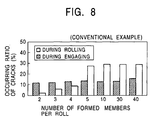
- Fig. 8 is a graph illustrating the relationship between
the number of formed members and the ratio of cracking of the
sleeve in a conventional example;
- Fig. 9 is a graph illustrating the relationship between
the sectional area ratio of the sleeve and the ratio of cracking
of the sleeve in a range of large sectional area ratios;
- Fig. 10 is a graph illustrating the relationship between
the sectional area ratio of the sleeve and the ratio of cracking
of the sleeve in a range of small sectional area ratios;
- Fig. 11A is a schematic sectional view in the rotation
axis direction of a conventional composite cemented carbide
roll;
- Fig. 11B is a schematic sectional view in a direction
perpendicular to the rotation axis of a conventional composite
cemented carbide roll;
- Fig. 12A is a schematic sectional view in the rotation
axis direction of another conventional composite cemented
carbide roll;
- Fig. 12B is a schematic sectional view in a direction
perpendicular to the rotation axis of another conventional
composite cemented carbide roll;
- Fig. 13 is a schematic sectional view illustrating a
typical roll suitable for application of the invention; and
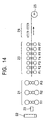
- Fig. 14 is a layout drawing illustrating a typical hot
rolling line suitable for application of the invention.
-
Best Mode for Carrying Out the Invention
-
Fig. 1 is a schematic sectional view in the rotation axis
direction of the composite cemented carbide roll of the present
invention; and Fig. 2 is a schematic sectional view in a
direction perpendicular to the rotation axis of the composite
cemented carbide roll of the invention. In Figs. 1 and 2, 1
represents an outer layer; 2, an inner layer; 3, an arbor; and
1A, a junction where previously sintered formed members are
integrally formed. The junction is not discernible in an
exterior view or even by an ultrasonic flaw detecting test.
The composite cemented carbide roll of the invention comprises
a sleeve having an outer layer 1 made of a cemented carbide
and an inner layer 2 made of a steel material diffusion-welded
onto the inner surface of the outer layer 1 is engaged with,
and fixed to, a steel arbor. The steel arbor 3 is longer than
the sleeve for attaching bearings to the both ends thereof.
The sleeve is engaged at the length center of the steel arbor
3 and fixed there. In Fig. 1, the outer layer 1 made of a
cemented carbide and the inner layer 2 made of a steel material
diffusion-welded to the inner surface of the outer layer 1 are
formed so as to have the same length, and steel side end rings
4 are attached to the both ends of the sleeve.
-
In the invention, the outer layer 1 made of a cemented
carbide is formed by integrally connecting a plurality of
previously sintered cylindrical formed members, and a sleeve
is formed by diffusion-welding the inner layer 2 made of a steel
material to the inner surface of the outer layer 1. A feature
of the invention is that the length of this sleeve is limited
within a range of from 520 to 6,000 mm. Another feature of
the sleeve is that, on a cross-section perpendicular to the
rotation axis as shown in Fig. 2, the ratio So/Si of the outer
layer sectional area So to the inner layer sectional area Si
should be within a range of from 0.3 to 20.
-
The cemented carbide of the outer layer 1 is prepared by
sintering a mixed cemented carbide powder made by adding from
5 to 50 mass % one or more selected from the group consisting
of metal powder of Co, Ni, Cr and Ti to powder of a cemented
carbide such as WC, TaC and TiC. A mixed cemented carbide
powder prepared by mixing from 5 to 50 mass % Co powder to WC
is preferable because of excellent wear resistance and surface
deterioration resistance and a satisfactory toughness. This
cemented carbide has a small thermal expansion coefficient
(linear expansion coefficient) as about a half that of the
conventional materials such as high-speed steel and semi-high-speed
steel. Because of the high hardness, the extent
of being flattened under a load applied during rolling is
smaller as compared with rolls made of the conventional
high-speed steel and semi-high-speed steel. The contact arc
length between the roll and the rolled material becomes
therefore shorter, thus reducing the contact time resulting
from roll rotation during rolling. An available advantage is
that this reduces the heat input into the roll, with a low
thermal expansion coefficient, leading to a smaller thermal
crown. A smaller absolute amount of thermal crown is desirable
since it permits improvement of the size and shape control
accuracy of the rolled material. The steel material of the
inner layer 2 should preferably be any of cast steel, gorged
steel, graphite cast steel, carbon steel and alloy carbon steel.
The arbor 3 can be prepared by tempering chromium steel,
chromium-molybdenum steel or high-speed steel.
-
A manufacturing method of the composite cemented carbide
roll of the present invention will now be described with
reference to Figs. 3 to 5.
-
Fig. 3 is a perspective view illustrating a plurality of
formed members 5 used for the sleeve of a composite cemented
carbide roll; and Figs. 4 and 5 are sectional views illustrating
the process of forming a sleeve by forming an inner layer 2
made of a steel material on the inner surface of the cemented
carbide sleeve 6 prepared by integrally connecting a plurality
of previously sintered cylindrical formed members 5.
-
The composite cemented carbide roll of the invention can
be manufactured through steps, for example, of charging the
powder (preparing a plurality of formed members per roll) →
CIP (cold isotropic pressuring) treatment → machining →
temporary sintering → machining → main sintering and HIP
treatment (integrally connecting a plurality of formed members,
and preparing a cemented carbide sleeve 6) → machining →
diffusion welding (diffusion-welding a steel cylindrical inner
layer member to the inner surface of the cemented carbide sleeve
6) → engagement and fixing (engaging the sleeve with the steel
arbor and fixing there).
-
The formed members are prepared by mixing a cemented
carbide material powder and a metal powder, and filling the
gap between the outer cylinder and the inner cylinder with the
resultant mixed cemented carbide material powder. The
resultant hollow formed members are temporarily sintered, and
as required after temporary sintering, the formed members are
machined into hollow cylindrical formed members 5 as shown in
Fig. 3. Preferable temporary sintering conditions include a
temperature within a range of from 550 to 800°C and a holding
time of from 1 to 3 hours.
-
For the purpose of increasing density of the hollow formed
members 5, it is desirable to apply a CIP treatment prior to
temporary sintering. The CIP forming conditions include, for
example, a pressure within a range of from 100 to 300 MPa and
a holding time within a range of from 5 to 60 minutes.
-
A plurality of the thus obtained hollow formed members
5 placed one on top of the other are integrated through diffusion
welding by main sintering and an HIP treatment to prepare a
cemented carbide sleeve 6 as shown in Fig. 4. The main
sintering and the HIP treatment are accomplished, for example,
in an Ar atmosphere, under a pressure within a range of from
100 to 200 MPa at a temperature within a range of from 1,100
to 1,200°C by holding for a period of from 0.5 to 2 hours, and
then further holding at a temperature of from 1,300 to 1,350°C
for 1 to 3 hours. By diffusion-welding a steel cylindrical
inner layer member to the inner surface of this sleeve, a sleeve
as shown in Fig. 5 is obtained. When diffusion-welding a forged
steel corresponding to a cylindrical SCM-440 having a thickness
of 50 mm onto the inner surface of a cemented carbide sleeve
6, a treatment is applied in an Ar atmosphere at a temperature
of from 1,200 to 1,300°C for a holding time of from 0.5 to 1
hour. As required, the sleeve is subjected to a machining such
as grinding or polishing. Then, the sleeve is engaged with,
and fixed to, the arbor by an ordinary process such as shrinkage
fitting or expansion fitting.
-
In the invention, as described above, the cemented carbide
sleeve is formed by integrating the plurality of previously
sintered cylindrical formed members 5 through main sintering
and the HIP treatment. The sleeve after integration has
therefore a high size accuracy. It is therefore possible to
reduce the amount of grinding, resulting in a satisfactory
manufacturing yield of cemented carbide and a high production
efficiency. It is, for example, possible to manufacture a long
large-diameter roll having a diameter of 600 mm and a sleeve
length of 520 mm or more.
-
In contrast, when manufacturing an outer layer of a long
sleeve comprising integrally formed cemented carbide members
by sintering, as shown in Figs. 11A and 11B, a larger amount
of grinding of the sleeve is required after sintering. This
results in a larger grinding load, requiring a very long period
of time for grinding. Because of the low manufacturing yield
of the cemented carbide powder, it is difficult to economically
manufacture efficiently a long large-diameter roll having, for
example, a diameter of 600 mm, and a sleeve length of 520 mm
or more.
-
In the invention, furthermore, a two-layer sleeve is
formed by diffusion-welding an inner layer sleeve made of a
steel material onto the inner surface of a cemented carbide
outer layer sleeve. It is possible to inhibit cracking of the
sleeve even during engagement in the manufacturing process or
during rolling, as compared with a cemented carbide sleeve 7
having no steel material on the inner surface thereof shown
in Figs. 12A and 12B.
-
Fig. 7 illustrates the cracking ratio of the sleeve outer
layer of the roll of the invention. Fig. 8 illustrates the
cracking ratio of the sleeve of the conventional composite
cemented carbide roll. The definition of the cracking ratio
is the same as in the description of Fig. 9. Comparison of
Figs. 7 and 8 clearly demonstrates that the cracking ratio is
lower for the sleeve outer layer of the roll of the invention.
The cracking ratio for the sleeve outer layer of the roll of
the invention is lower since a compressive stress acts on the
sleeve outer layer.
-
The compressive stress acts on the outer layer sleeve for
the following reasons. When cooling the sleeve after
diffusion-welding the steel inner layer member to the inner
surface of the cemented carbide sleeve at a high temperature,
the amount of shrinkage becomes larger because of the thermal
expansion coefficient of the steel inner layer member larger
than that of the cemented carbide sleeve, and this difference
in the amount of shrinkage produces a tensile stress in the
inner layer, and a compressive stress in the outer layer.
-
Both Figs. 7 and 8 illustrate the results of investigation
of a roll for a cold tandem mill having an outside diameter
of 560 mm, a barrel length of 1,800 mm, and a total length of
3,500 mm.
-
The relationship between the number of formed members per
roll and the manufacturing yield of mixed cemented carbide
powder, and the number of formed members per roll as well as
the cracking ratio of the sleeve outer layer during engagement
when manufacturing the composite cemented carbide roll of the
invention by the above-mentioned method were investigated.
Furthermore, the cracking ratio of the sleeve outer layer
during rolling was studied by subjecting composite cemented
carbide rolls which could be manufactured without cracking
during manufacturing.
-
Figs. 6 and 7 shown the results, respectively. Fig. 6
is a graph illustrating the relationship between the number
of formed members per roll and the manufacturing yield of
cemented carbide in an example of the invention; and Fig. 7
is a graph illustrating the number of formed members per roll,
the cracking ratio of the sleeve outer layer during engagement,
and the cracking ratio of the sleeve outer layer during rolling
in an example of the invention. In Fig. 6, the manufacturing
yield of cemented carbide is calculated by dividing the weight
of the cemented carbide sleeve by the charged weight of the
mixed cemented carbide powder charged into the (plurality of)
formed members.
-
The result illustrated in Fig. 6 was obtained for the
following reasons. When the number of formed members is under
five, the longer barrel length per formed member leads to a
large thermal shrinkage resulting from cooling after sintering.
Slightly larger formed members would be manufactured with a
margin, and moreover, the shape of shrinkage becomes warped.
The amount of grinding in the course of manufacture of the
cemented carbide sleeve increases, with surface deterioration
of the manufacturing yield of the cemented carbide. When the
number of formed members is over 30, on the other hand, there
would be more surfaces in contact of the piled formed members,
leading to a corresponding increase in the amount of grinding
of the cemented carbide sleeve, thus resulting in a poorer
manufacturing yield of the cemented carbide.
-
The result shown in Fig. 7 reveals that a number of formed
members per roll over 30 corresponds to an increase in the
cracking ratio. The increase in the number of surfaces in
contact of the formed members leads to easier cracking starting
therefrom. It is needless to mention that a larger amount of
grinding results in a longer grinding time and hence in a lower
production efficiency.
-
With a view to improving the manufacturing yield of
cemented carbide, and inhibiting cracking of the cemented
carbide sleeve during engagement and during rolling, in the
composite cemented carbide roll of the invention, as described
above, the number of formed members should preferably be within
a range of from 5 to 30.
-
The reasons of limiting the ratio So/Si of the sectional
area of the sleeve outer layer to the sectional area Si of the
inner layer in a cross-section perpendicular to the rotation
axis (hereinafter also referred to simply as the "sectional
area ratio") within the above-mentioned range will be
described.
-
The present inventors carried out an experiment of use
in cold tandem mill by manufacturing a roll for cold tandem
mill, having an outside diameter of 560 mm, a barrel length
of 1,800 mm, and a total length of 3,500 mm. A cemented carbide
sleeve formed through integration of six previously sintered
cylindrical formed members was prepared for this experiment.
The total of the thickness of the cemented carbide outer layer
and the thickness of the steel inner layer diffusion-welded
to the inner surface thereof was kept constant at 150 mm, and
a plurality of rolls under these conditions, with the sectional
area ratio So/Si ranging from 0.12 to 25. They studied the
cracking ratio on the sleeve outer layer during engagement of
the sleeve with the steel arbor. When the sleeve was not
cracked, two rolls in a set were subjected to cold rolling to
investigate the cracking ratio in the sleeve outer layer during
rolling. The cracking ratio during engagement of the sleeve
with the steel arbor and the cracking ratio during rolling were
determined as follows.
-
Two hundred rolls were engaged at respective sectional
ratios So/Si shown in Figs. 9 and 10. A cracking ratio of 1%
during engagement means that cracking occurred twice during
engagement for 200 rolls engaged and manufactured. Additional
rolls were manufactured in a number equal to that of rolls having
cracked during engagement. Two hundred rolls (100 sets) were
subjected to rolling with respective sectional area ratios
So/Si shown in Figs. 9 and 10. For example, a cracking ratio
of 2% during rolling means that, from among the 100 sets of
roll subjected to rolling, cracks were produced in one or both
rolls for two sets.
-
Cracking ratios in the sleeve outer layer during
engagement of the sleeve with the steel arbor and during rolling
are represented in Figs. 9 and 10. Fig. 10 shows an enlarged
view of the region of smaller sectional area ratios So/Si in
Fig. 9.
-
It is known from Figs. 9 and 10 that the cracking ratio
in the sleeve outer layer during engagement is 0 for a small
sectional area ratio So/Si, increases according as the
sectional area ratio So/Si increases, and steeply increases
when the sectional area ratio So/Si exceeds 20. The cracking
ratio in the sleeve outer layer during rolling, on the other
hand, is 0 for a large sectional area ratio So/Si, increases
according as the sectional area ratio So/Si decreases, and
steeply increases when the sectional area ratio So/Si becomes
under 0.3.
-
In the invention, therefore, with a view to preventing
cracking in the sleeve outer layer during engagement, the
sectional ratio So/Si should be 20 or lower, or preferably,
15 or lower. For preventing cracking in the sleeve outer layer
during rolling, on the other hand, the sectional area ratio
So/Si should be 0.3 or higher, or preferably, 0.8 or higher.
-
For the reasons as described above, in the invention, the
ratio So/Si of the sectional area So of the sleeve outer layer
1 to the sectional area Si of the inner layer 2 should be within
a range of from 0.3 to 20, or preferably, from 0.8 to 15.
-
When the sleeve sectional area ratio So/Si is 0.8 or higher
within the range of the invention, it is possible to adopt a
larger thickness for the outer layer 1 made of the cemented
carbide, even if the sleeve thickness is the same as in the
conventional composite cemented carbide roll which should have
a sectional area ratio of 0.7 or under. As a result, the margin
for roll grinding becomes larger, allowing reduction of the
critical diameter for decommissioning and extension of the roll
service life. Because of the possibility to use a larger
thickness for the outer layer 1 made of the cemented carbide,
the roll strength increases, and it is possible to subject the
roll to rolling under a higher rolling load.
-
Application of the composite cemented carbide roll of the
invention as a work roll for a cold tandem mill with an outside
diameter within a range of from 150 to 1,500 mm ensures a
remarkable improvement of heat scratch resistance and surface
gloss of the rolled material as compared with the conventional
steel roll.
-
Application of the composite cemented carbide roll of the
invention as a work roll for a hot roughing mill with an outside
diameter within a range of from 5,000 to 1,500 mm ensures a
remarkable improvement of size and shape control property by
reduction of thermal crown as compared with the conventional
steel roll.
-
Application of the composite cemented carbide roll of the
invention as a work roll for a hot finishing mill with an outside
diameter within a range of from 400 to 1,400 mm ensures a
remarkable improvement of size and shape control property by
reduction of thermal crown as compared with the conventional
steel roll.
-
Application of the composite cemented carbide roll of the
invention as a work roll for a plate mill with an outside
diameter within a range of from 500 to 1,500 mm ensures a
remarkable improvement of size and shape control property by
reduction of thermal crown as compared with the conventional
steel roll.
-
Application of the composite cemented carbide roll of the
invention as a work roll for a section mill with an outside
diameter within a range of from 600 to 2,000 mm ensures a
remarkable improvement of size and shape control property by
reduction of thermal crown as compared with the conventional
steel roll. In all cases including the uses described above,
wear resistance, cracking resistance and surface deterioration
resistance are remarkably improved as compared with the
conventional steel roll.
-
In the present invention, the rolls having rolling section
surface layer made of a cemented carbide are used as work rolls
for at least a stand of a roughing mill. The cemented carbide
is prepared by sintering a mixed cemented carbide powder
obtained by adding, in an amount of from 5 to 50 mass %, one
or more selected from the group consisting of metal powder
materials of Co, Ni, Cr and Ti to cemented carbide powder of
WC, TaC or TiC. The mixed cemented carbide powder should
preferably be one prepared by sintering WC - 5 to 50 mass %
Co powder which is preferable because of excellent wear
resistance and surface deterioration resistance and a
satisfactory toughness.
-
This inhibits surface deterioration caused by seizure on
the steel sheet surface after hot rolling. In a stand using
such rolls as work rolls, cracking does not occur and progress
of wear is inhibited even without supply of rolling oil.
-
The roll used in the invention has an arbor, an inner layer
sleeve made of a steel material, and an outer layer sleeve member
made of a cemented carbide. The outer layer sleeve member
should preferably be formed by integrally connecting a
plurality of cemented carbide formed members in the roll axial
direction. This makes it possible to manufacture the sleeve
member at a high accuracy and with a satisfactory operability.
This roll has an inner layer sleeve made of a steel material
between the arbor and the cemented carbide connected sleeve.
-
As compared with direct connection of the cemented carbide
connected sleeve and the arbor by shrinkage fit or expansion
fit, tensile stress acting in the axial direction of the
cemented carbide connected sleeve after completion can be
alleviated, and this is favorable for preventing cracking of
the cemented carbide connected sleeve during manufacture and
during rolling.
-
The manufacturing method of the above-mentioned cemented
carbide connected sleeve comprises the steps of rubber-forming
a plurality of hollow members (cemented carbide formed members)
divided along a plane crossing the roll center axis, and after
temporarily sintering, integrating the hollow members by HIP
(hot isotropic pressuring) connection. According to this
method, the hollow members in the temporary sintering are
reduced in size, so that production of thermal strain is
inhibited, and even when manufacturing a sleeve for a
large-diameter long roll such as a work roll for a hot roughing
mill, manufacture can be performed at a high operability,
giving products of a high size accuracy.
-
The arbor comprises a metal shaft material such as cast
steel, forged steel or cast iron as is commonly used.
-
Fig. 13 is a schematic sectional view illustrating a
typical roll suitable for application of the invention. The
cemented carbide connected sleeve 1 is engaged with the barrel
of the steel arbor 3 via the inner layer sleeve 2 made of a
steel material and fixed with a steel side end ring 4.
-
Fig. 14 is a layout drawing illustrating a typical hot
rolling line suitable for application of the invention.
Sequentially from the line upstream side, a reheating furnace
22, a width press apparatus 23, a roughing mill 21, a finishing
mill 20, a cooling system 24 and a coiler 25 are arranged. In
this example, the roughing mill 23 is composed of three stands
R1, R2 and R3, and the finishing mill 20 is composed of seven
stands F1, F2, ..., F7. When a roughing mill comprises a
plurality of stands as in this case, it is desirable to apply
the invention to the upstream side stands in which the rolled
material temperature is higher. In the finishing mill, the
stands to which the cemented carbide roll is applied should
preferably be stands on the latter stage side on which the amount
of scale becomes larger. A better result is available
according as stands to which the roll of the invention is applied
are increased in number in response to availability of economic
margin.
(Example 1)
-
As Example 1 of the invention, two rolls for a cold tandem
mill, each having an outside diameter of 560 mm, a barrel length
of 1,800 mm and a total length of 3,500 mm, as shown in Figs.
1 and 2, were manufactured. The manufacturing yield of the
cemented carbide when manufacturing the sleeve, the status of
cracking on the sleeve outer layer during engagement, and the
total period of time consumed for grinding each roll made of
the cemented carbide were investigated.
-
In the example 1 of the invention, a cemented carbide
sleeve was prepared by coaxially piling six previously sintered
cylindrical formed members per roll, then subjecting the
members to main sintering and an HIP treatment, and integrating
them. A cylindrical inner layer member made of a molten steel
material was diffusion-welded to the inner surface of this
cemented carbide sleeve. The resultant sleeve was engaged with
the steel arbor and fixed thereto to manufacture two composite
cemented carbide rolls.
-
The formed members were prepared as follows. WC powder
having the chemical composition shown in Table 1 and an average
particle size within a range of from 3 to 5 µm and Co metal powder
having an average particle size within a range of from 1 to
2 µm were mixed together with WC balls as mixing medium for two
days. Formed members were prepared by filling the gap between
double-cylindrical rubber die outer cylinder and inner
cylinder with the resultant mixed cemented carbide powder. The
double cylindrical rubber die outer cylinder has an inside
diameter of 835 mm and a length of 425 mm, and the inner cylinder
has an outside diameter of 350 mm and a length of 425 mm. A
pipe-shaped spindle having a diameter of 345 mm and a length
of 500 mm was inserted into the center portion of the
double-cylinder, and a rubber die was placed on a hammer-type
charging machine. A series of processes of charging the mixed
powder of cemented carbide material in batches of equal amounts ,
and then pressurizing the same were repeated.
-
Other detailed conditions are shown in Table 1.
-
The treatment conditions for diffusion-welding the
cylindrical inner layer member made of a molten steel material
to the inner surface of the cemented carbide sleeve are shown
in Table 2.
-
An example 2 of the invention was carried out in the same
manner as in example 1 of the invention except that four
previously sintered formed members were used, and each formed
member had a length as shown in Table 1. As in example 1 of
the invention, the manufacturing yield of the cemented carbide
when manufacturing the sleeve, the status of cracking on the
sleeve outer layer during engagement, and the total period of
time consumed for grinding each roll made of the cemented
carbide were investigated.
-
In the example 2 of the invention, the outer cylinder and
the inner cylinder had a length of 640 mm, and charging was
accomplished by appropriately changing the length of the
pipe-shaped spindle.
-
The composite cemented carbide roll of a conventional
example 1 having structure as shown in Figs. 12A and 12B was
manufactured under conditions shown in Table 1, and as in the
example 1 of the invention, the manufacturing yield of the
cemented carbide when manufacturing the sleeve, the status of
cracking on the sleeve outer layer during engagement, and the
total period of time consumed for grinding each cemented
carbide roll were investigated.
-
The formed members were prepared in the same manner as
in the example 1 of the invention, except that the outer cylinder
of the double-cylinder rubber die had an inside diameter of
835 mm and a length of 2,800 mm, and the inner cylinder had
an outside diameter of 350 mm. A pipe-shaped spindle having
a diameter of 345 mm was inserted with various appropriate
lengths into the center portion of the double cylinders.
-
The composite cemented carbide roll of the conventional
example 2 having the structure shown in Figs. 11A and 11B was
manufactured under conditions shown in Table 1, and as in the
example 1 of the invention, the manufacturing yield of the
cemented carbide when manufacturing the sleeve, the status of
cracking on the sleeve outer layer during engagement, and the
total period of time consumed for grinding each roll were
investigated.
-
Formed members were prepared in the same manner as in the
example 1 of the invention. The outer cylinder of the
double-cylinder rubber die had an inside diameter of 900 mm
and a length of 6,000 mm, and the inner cylinder had an outside
diameter of 219 mm. A pipe-shaped spindle having a diameter
of 219 mm and an appropriate length was inserted into the center
portion of the double cylinders.
-
The manufacturing yield of a cemented carbide when
manufacturing the sleeve, the status of cracking on the outer
layer of the sleeve during engagement, and the total period
of time consumed for grinding each roll were investigated.
-
The result shown in Table 2 reveals that the composite
cemented carbide rolls of the examples 1 and 2 of the invention
are not susceptible to cracking on the sleeve outer layer during
engagement of the sleeve with the steel arbor, and can be used
for rolling. The result shown in Table 2 suggests also that
the manufacturing yield is higher than in the conventional
example 2 and the number of days required for grinding the roll
can be reduced. In the case of the example 1 of the invention,
in which six previously sintered formed members were used, the
manufacturing yield of the mixed cemented carbide powder could
be improved as compared with that in the example 2 of the
invention.
-
The composite cemented carbide roll of the conventional
example 1 showed a lower manufacturing yield of the mixed
cemented carbide powder and a longer period of time for grinding
the roll. Because of the production of cracks in the sleeve
during engagement, the roll could not be used for rolling.
(Example 2)
-
Composite cemented carbide rolls having the structure as
shown in Figs. 1 and 2, and the roll size shown in Table 3 and
comprising the members shown in Table 4 were used as an example
of the invention, and properties were investigated by
incorporating them in various rolling mills.
-
The cemented carbide sleeve shown in Table 4 was prepared
by integrating the plurality of previously sintered formed
members shown in Table 5 through main sintering and an HIP
treatment. The manufacturing yield of the cemented carbide
powder was investigated when manufacturing the cemented
carbide sleeve.
-
Composite cemented carbide rolls having the structure
shown in Figs. 11A and 11B and a roll size shown in Table 3
and comprising members shown in Table 4 were formed by
integrating sleeve outer layers as a conventional example.
Rolls having the same roll size as in the example of the
invention shown in Table 3 and a roll material shown in Table
5 were used as comparative examples. Properties of these
samples were investigated by incorporating the samples of the
example of the invention, the conventional example and the
comparative example. On a cold tandem mill, investigation was
carried out by incorporating the samples into the fifth stand
from among the five stands in total. On a hot finishing tandem
mill, the samples were incorporated for investigation into the
first and seventh stands from among seven stands in total.
-
Table 5 shows the critical number of rolled steels, the
crack depth, the thermal crown, acceptability of shape of
rolled steels in the example of the invention, the conventional
example and the comparative example, and the manufacturing
yield of the cemented carbide during roll manufacture in the
example of the invention and the conventional example.
-
The roll properties in the example of the invention, the
conventional example and the comparative example, and the
manufacturing yield of the cemented carbide during manufacture
of rolls in the example of the invention and the conventional
example are shown.
-
The result shown in Table 5 suggests that the composite
cemented carbide roll of the example of the invention in which
the sleeve has a length within a range of from 520 to 6,000
mm is more excellent in the manufacturing yield of the cemented
carbide powder than the composite cemented carbide roll of the
conventional example. When used as a work roll for a rolling
mill, the composite cemented carbide roll of the example of
the invention is more excellent in wear resistance and surface
deterioration resistance than the cold semi-high-speed steel
roll and the hot high-speed steel roll of the comparative
example. The former has therefore a larger critical number
of rolled steels, a more excellent cracking resistance and a
smaller thermal crown, resulting in a better shape of the rolled
steels than in the roll of the comparative example.
(Example 3)
-
Two rolls for each division for a cold tandem mill were
manufactured as shown in Table 6, with an outside diameter of
560 mm x a barrel length of 1,800 mm x a total length of 3,500
mm. The manufacturing yield of the cemented carbide when
manufacturing the sleeve, the status of cracking in the sleeve
outer layer during engagement, and the total period of time
consumed for grinding each cemented carbide roll were
investigated. Not cracking rolls were subsequently subjected
to rolling to investigate the rolling throughput representing
the amount of rolling up to decommissioning of the roll.
-
In the example of the invention A1, a composite cemented
carbide roll having the structure shown in Figs. 1 and 2 was
used. A cemented carbide sleeve was formed by coaxially piling
six previously sintered cylindrical formed members per roll,
subjecting the same to main sintering and an HIP treatment,
and then integrating the same. A cylindrical inner layer
member comprising a melted carbon steel was diffusion-welded
to the inner surface of this cemented carbide sleeve, and a
composite cemented carbide roll was obtained by engaging the
resultant sleeve with a steel arbor.
-
Formed members were prepared as follows. WC powder having
a chemical composition shown in Table 1 and an average particle
size within a range of from 3 to 5 µm and Co metal powder having
an average particle size within a range of from 1 to 2 µm were
mixed for two days using WC balls as the mixing medium. The
formed member was prepared by filling the gap between the outer
cylinder and the inner cylinder of a double-cylinder rubber
die with the resultant mixed cemented carbide powder. In the
double-cylinder rubber die, the outer cylinder had an inside
diameter of 835 mm, and a length of 425 mm, and the inner cylinder
had an outside diameter of 350 mm and a length of 425 mm. A
pipe-shaped spindle having a diameter of 350 mm and a length
of 500 mm was inserted into the center portion of the double
cylinder, and a rubber die was placed on a hammer type charging
machine. A series of processes of charging the mixed cemented
carbide powder in equal patches and then pressurizing the same
were repeated.
-
Preparation of the individual formed members in the
example of the invention A2 was accomplished by inserting a
pipe-shaped spindle having a diameter of 490 mm and a length
of 500 mm into the center portion of a double-cylinder rubber
die comprising an outer cylinder having an inside diameter of
835 mm and a length of 425 mm and an inner cylinder having an
outside diameter of 490 mm and a length of 425 mm.
-
A composite cemented carbide roll of the conventional
example A3 was manufactured by using two formed members per
roll with a structure shown in Figs. 12A and 12B.
-
Preparation of the individual formed members in the
conventional example A3 was accomplished by inserting a
pipe-shaped spindle having a diameter of 350 mm and a length
of 3,500 mm into the center portion of a double-cylinder rubber
die comprising an outer cylinder having an inside diameter of
835 mm and a length of 2,800 mm and an inner cylinder having
an outside diameter of 350 mm and a length of 2,800 mm.
-
A composite cemented carbide roll having the structure
shown in Fig. 11A and 11B was manufactured in the conventional
example A4.
-
Mixed cemented carbide powder was charged into a gap in
which a pipe-shaped spindle having a diameter of 370 mm and
a length of 6,500 mm was inserted at the center portion of a
double-cylinder rubber die comprising an outer cylinder having
an inside diameter of 900 mm and a length of 6,000 mm and an
inner cylinder having an outside diameter of 370 mm and a length
of 6,000 mm.
-
Table 7 shows the yield of mixed cemented carbide powder,
the status of cracking in the sleeve during engagement, the
number of days consumed for grinding, and the rolling
throughput.
-
It is known from the result shown in Table 7 that the
composite cemented carbide rolls of the examples of the
invention A1 and A2 are not susceptible to cracking in the sleeve .
outer layer during engagement, and are applicable for rolling,
permit improvement of the manufacturing yield of cemented
carbide over that in the conventional example A4, and makes
it possible to reduce the number of days required for grinding.
-
In the example of the invention A1, in which the sectional
area ratio was limited within a range of from 0.8 to 15, the
rolling throughput could be increased as compared with the
example of the invention A2 and the conventional example A4
in which the sectional area ratio was limited to 0.7 or lower.
-
The composite cemented carbide roll of the conventional
example A3 could not be used for rolling since the manufacturing
yield of the mixed cemented carbide powder was low, and cracks
were produced in the sleeve outer layer during engagement.
(Example 4)
-
Two rolls for a section mill were manufactured for each
division under the conditions shown in Table 8, with an outside
diameter of 1,500 mm, a barrel length of 900 mm and a total
length of 3,800 mm. The manufacturing yield of the cemented
carbide when manufacturing the sleeve, the status of cracking
in the sleeve outer layer during engagement, and the total
period of time consumed for grinding per cemented carbide roll
were investigated. The sleeves not cracking were subsequently
used for rolling to investigate the rolling throughput for a
period of up to decommissioning of the rolls.
-
In the example of the invention B1, the composite cemented
carbide rolls having the structure shown in Figs. 1 and 2 were
used. Five previously sintered cylindrical formed members per
roll were coaxially piled, then subjected to main sintering
and an HIP treatment, and integrating the same, thereby forming
a cemented carbide sleeve. A cylindrical inner layer member
made of cast steel was diffusion-welded to the inner surface
of this cemented carbide sleeve. The resultant sleeve was
engaged with the steel arbor and fixed thereto. Composite
cemented carbide rolls were thus manufactured one by one.
-
The formed members were prepared in the same manner as
in Example 1. A pipe-shaped spindle having a diameter of 960
mm and a length of 320 mm was inserted into the center portion
of a double-cylinder rubber die comprising an outer cylinder
having an inside diameter of 1,975 mm and a length of 255 mm
and an inner cylinder having an outside diameter of 960 mm and
a length of 255 mm. The rubber die was placed on a hammer type
charging machine to carry out charging.
-
In the example of the invention B2, a sleeve was
manufactured in the same manner as in the example of the
invention B1, using a different sleeve sectional area ratio
So/Si. In the conventional examples B3 and B4, sleeves were
manufactured in the same manner as in the conventional examples
A3 and A4 of the aforementioned Example 3, respectively.
-
Table 9 shows the yield of mixed cemented carbide powder,
the status of cracking of the sleeve during engagement, the
number of days required for grinding, and the rolling
throughput.
-
It is known from the result shown in Table 9 that the
composite cemented carbide rolls of the examples of the
invention B1 and B2 do not suffer from cracking in the sleeve
outer layer during engagement; the manufacturing yield of the
cemented carbide can be improved over that in the conventional
example 4; and it is possible to reduce the number of days for
grinding.
-
In the example of the invention B1, in which the sectional
area ratio was within a range of from 0.8 to 15, the rolling
throughput could be increased as compared with the example of
the invention B2 in which the sectional area ratio was limited
to 0.7 or less, and the conventional example B4.
-
The composite cemented carbide roll of the conventional
example B3 showed a manufacturing yield of mixed cemented
carbide powder lower than in the examples of the invention B1
and B2. Since cracks occurred in the sleeve outer layer during
engagement, the roll could not be applied in rolling.
(Example 5)
-
The composite cemented carbide roll having the structure
shown in Figs. 1 and 2 was used as an example of the invention.
Table 10 shows the roll size, and Table 11, the member material
and the size thereof.
-
The cemented carbide sleeve shown in Table 11 was formed
by integrating previously sintered formed members in a number
shown in Table 12, through main sintering and an HIP treatment.
The manufacturing yield of cemented carbide powder was
investigated during manufacture of the cemented carbide
sleeve.
-
The composite cemented carbide roll having the structure
shown in Figs. 11A and 11B was used as a conventional example.
Table 10 shows the roll size, and Table 11 shows the member
material and size. The sleeve outer layer is formed by
integrating the formed members.
-
A roll having the same size as in the example of the
invention shown in Table 10 and made of the material shown in
Table 12 was used as a comparative example.
-
Properties of the example of the invention, the
conventional example and the comparative example were
investigated by incorporating them into various rolling mills.
In a cold tandem mill, the roll was incorporated in the fifth
stand from among five stands in total for investigation.
Investigation was carried out on a hot finishing tandem mill
by incorporating the roll in the first and seventh stands from
among seven stands in total.
-
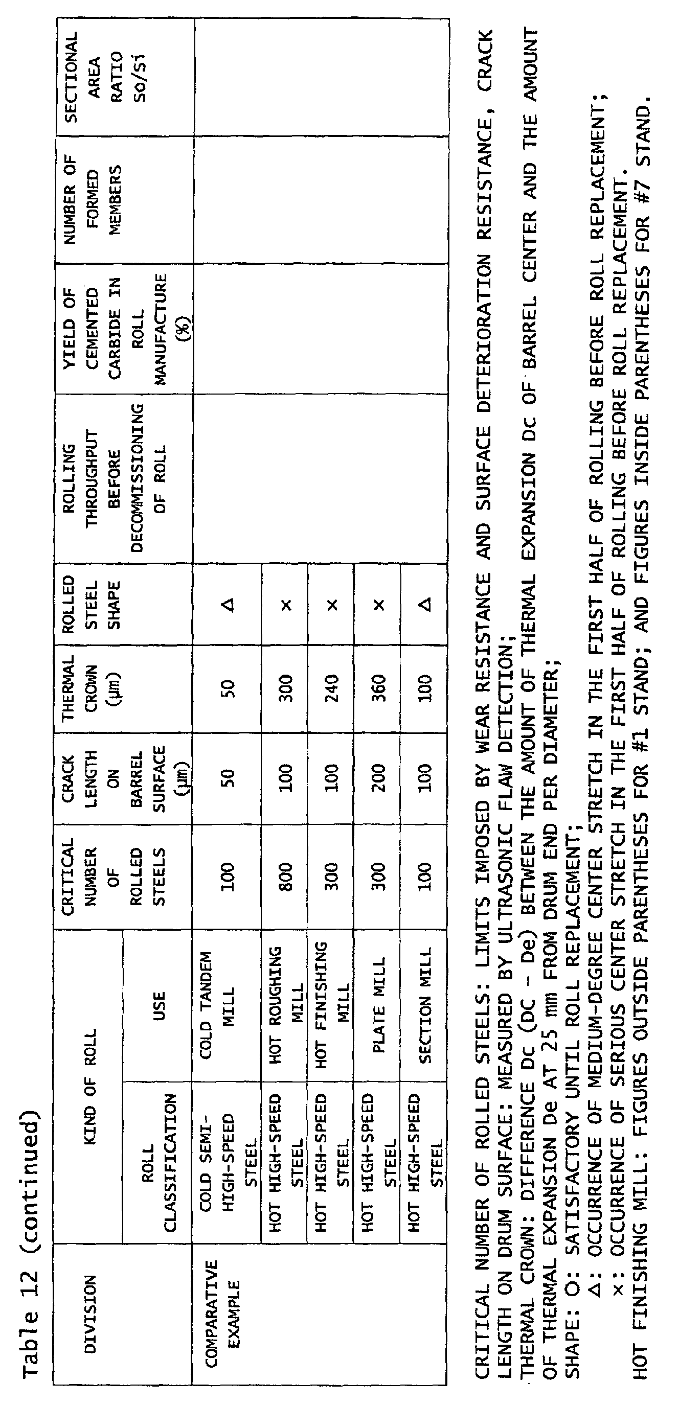
Table 12 shows the critical number of rolled steels, the
crack depth, thermal crown, acceptability of shape of the
rolled steels, the manufacturing yield of cemented carbide
during roll manufacture in the example of the invention and
the conventional example, and the rolling throughput up to roll
decommissioning for the example of the invention, the
conventional example and the comparative example.
-
It is known from the result shown in Table 12 that the
composite cemented carbide roll of the example of the invention
shows a higher manufacturing yield of the cemented carbide
powder than the composite cemented carbide roll of the
conventional example, and permits increase in the rolling
throughput.
-
The composite cemented carbide roll of the example of the
invention, when used as a work roll of various rolling mills,
is more excellent in wear resistance and surface deterioration
resistance than a cold semi-high-speed steel roll or a hot
high-speed steel roll of the comparative example. It provides
a larger critical number of rolled steels, is excellent in
cracking resistance, and produces smaller thermal crown,
resulting in a better shape of the rolled steels than in the
comparative example.
(Example 6)
-
A work roll of the material shown in Table 13 was
incorporated in a roughing mill and a finishing mill on a hot
rolling line shown in Fig. 14. SUS 430 ferrite-based stainless
steel was rolled into 100 coils, respectively, thereby
observing the surface condition of the rolled steel sheets.
The crack depth of the work roll for the roughing mill was
investigated.
-
The rolling portion of the roughing mill work roll had
an outside diameter of 1,300 mm and a width of 2,000 mm. The
rolling portion of the finishing mill work roll had an outside
diameter of 900 mm and a width of 2,000 mm. The number of
roughing passes was seven (R1x3+R2x3+R1x1).
-
In Table 13, "cemented carbide" means a cemented carbide
roll, which has a structure shown in Fig. 13. The cemented
carbide connected sleeve was manufactured from tungsten
carbide (WC) to which Co is added in an amount of 20 mass %
by longitudinally HIP-connecting four WC-Co alloy hollow
members each having a thickness of 230 mm and a length of 500
mm formed by the rubber forming process. This sleeve was
diffusion-welded to an inner layer sleeve comprising a steel
material, and engaged with a steel arbor, thus obtaining a
cemented carbide roll. In Table 13, "steel" means a steel roll,
which was manufactured by tempering high-speed steel.
-
In a stand using the cemented carbide roll, only roll
cooling water was supplied to the work roll, and in a stand
using a steel roll, rolling was conducted while supplying roll
cooling water and a rolling oil.
-
The result is shown in Table 13. In the example of the
invention, the steel sheet surface after rolling was
satisfactory, being free from surface deterioration, even
without supply of a rolling oil to the cemented carbide roll.
The cemented carbide roll after rolling was completely free
from cracking at the hollow member connected portion as well
as the other portions.
(Example 7)
-
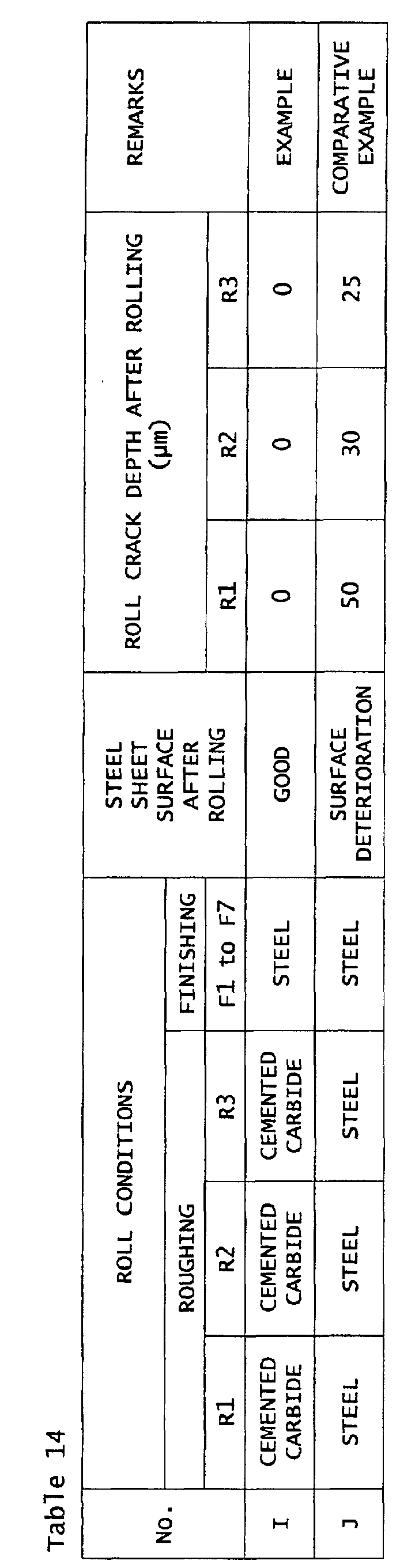
A work roll of the material shown in Table 14 was
incorporated in a roughing mill and a finishing mill on a hot
rolling line shown in Fig. 14. Ordinary low-carbon steel was
rolled into 30 coils, respectively. The surface condition of
the steel sheet was observed after rolling, and the crack depth
of the roughing mill work roll was investigated.
-
The rolling portion of the roughing mill work roll had
an outside diameter of 1,300 mm and a width of 2,000 mm. The
rolling portion of the finishing mill work roll had an outside
diameter of 900 mm and a width of 2,000 mm. The number of
roughing passes was seven (R1x3+R2x3+R1x1).
-
The words "cemented carbide" and "steel" in Table 14 mean
the same things as the words "cemented carbide" and "steel"
in Table 13. In a stand using the cemented carbide roll, only
roll cooling water was supplied to the work roll, and in a stand
using the steel roll, rolling was conducted while supplying
roll cooling water and a rolling oil.
-
The result is shown in Table 14. In the example of the
invention, the steel sheet surface after rolling was
satisfactory, being free from surface deterioration, even
without supply of a rolling oil to the cemented carbide roll.
The cemented carbide roll after rolling was completely free
from cracking at the hollow member connected portion as well
as the other portions.
(Example 8)
-
A work roll of the material shown in Table 15 was
incorporated in a roughing mill and a finishing mill on a hot
rolling line shown in Fig. 14. SUS 430 ferrite-based stainless
steel was rolled into 100 coils, respectively, thereby
observing the surface condition of the rolled steel sheets
after rolling, and the amount of wear of the finishing mill
work roll (per roll radius) was investigated.
-
The rolling portion of the roughing mill work roll had
an outside diameter of 1,300 mm and a width of 2,000 mm. The
rolling portion of the finishing mill work roll had an outside
diameter of 900 mm and a width of 2,000 mm. The number of
roughing passes was seven (= R1x3+R2x3+R1x1).
-
In Table 15, "cemented carbide" means a cemented carbide
roll, which has the structure shown in Fig 13. The cemented
carbide connected sleeve was manufactured from tungsten
carbide (WC) to which Co is added in an amount of 20 mass %
by longitudinally HIP-connecting four WC-Co alloy hollow
members each having a thickness of 350 mm and a length of 500
mm formed by the rubber forming process. This sleeve was
diffusion-welded to an inner layer sleeve comprising a steel
material, and engaged with a steel arbor, thus obtaining a
cemented carbide roll. In Table 15, "steel" means a steel roll,
which was manufactured by tempering high-speed steel.
-
In a stand using the cemented carbide roll, only roll
cooling water was supplied to the work roll, and in a stand
using the steel roll, rolling was conducted while supplying
roll cooling water and a rolling oil.
-
The result is shown in Table 15. In the example of the
invention, the steel sheet surface after rolling was
satisfactory, being free from surface deterioration, even
without supply of a rolling oil to the cemented carbide roll.
The cemented carbide roll after rolling showed almost no wear.
The cemented carbide roll after rolling was free from cracking.
(Example 9)
-
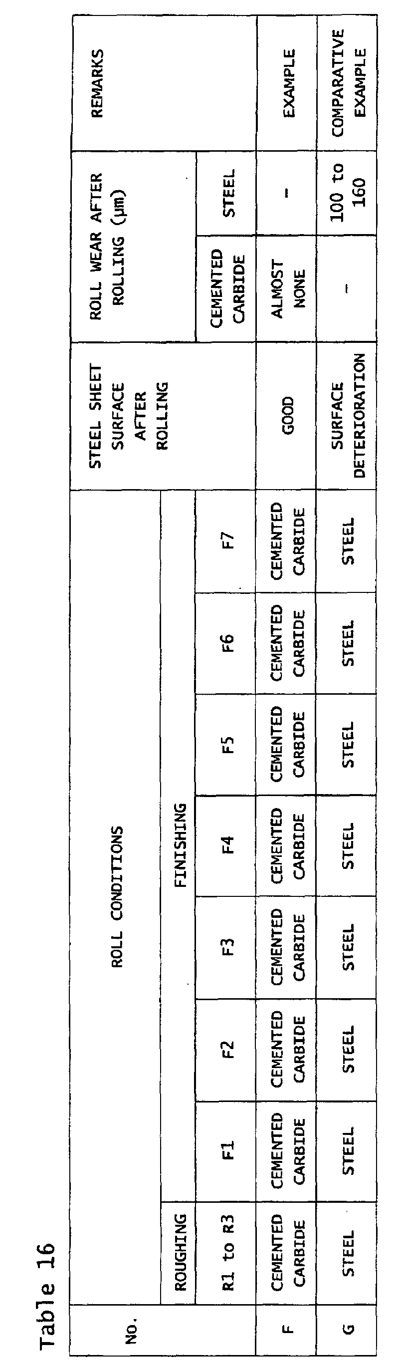
Work rolls of the material shown in Table 16 were
incorporated into a roughing mill and a finishing mill on a
hot rolling line shown in Fig. 14. Ordinary low-carbon steel
was rolled into 100 coils, respectively. After this rolling,
the surface condition of the steel sheet was observed, and the
amount of wear (per roll radius) of the work roll of the
finishing mill was investigated.
-
The rolling portion of the roughing mill work roll had
an outside diameter of 1,300 mm and a width of 2,000 mm, and
the rolling portion of the finishing mill work roll had an
outside diameter of 900 mm and a width of 2,000 mm. The number
of roughing rolling passes was seven (=R1x3+R2x3+R1x1).
-
The words "cemented carbide" and "steel" in Table 16 have
the same meanings as the words "cemented carbide" and "steel"
in Table 15. In the stand using the cemented carbide roll,
only roll cooling water was supplied to the work roll, and in
the stand using the steel roll, rolling was conducted while
supplying roll cooling water and a rolling oil to the work roll.
-
The result is shown in Table 16. In the example of the
invention, the steel sheet surface after rolling wash
satisfactory, being free from surface deterioration, even
without supply of a rolling oil. The cemented carbide roll
showed almost no wear. The cemented carbide roll after rolling
was free from cracks.
Industrial Applicability
-
According to the composite cemented carbide roll of the
present invention, it is possible to manufacture rolls at a
high yield, efficiently, and while inhibiting cracking, even
in the case of a long large-diameter roll. When applying the
roll for various manners of rolling, it is possible to stably
accomplish rolling while inhibiting cracking.
-
According to the invention, therefore, application of the
cemented carbide roll to a roughing mill and a finishing mill
of hot rolling as a work roll provides excellent advantages
of permitting prevention of surface deterioration of steel
sheet caused by seizure without the need to supply a rolling
oil, and prevention of roll cracking and wear.
| ITEM | EXAMPLE 1 | EXAMPLE 2 | CONVENTIONAL EXAMPLE 1 | CONVENTIONAL EXAMPLE 2 |
| ROLL CONFIGURATION | FIGS. 1,2 2 | FIGS. 1,2 -, | FIGS. 12A, 12B | FIGS. 11A, 11B |
| NUMBER OF FORMED MEMBERS ROLL | 6 | 4 | 2 | 1 (INTEGRALLY FORMED) |
| ROLL SIZE | OD 560 mm x BARREL LENGTH 1,800 mm
x TOTAL LENGTH 3,500 mm |
| CEMENTED CARBIDE SLEEVE SIZE | OD (mm) | 560 | | * | * |
| ID (mm) | 335 | * | 360 | * |
| LENGTH (mm) | 1800 | * | * | * |
| COMPOSITION OF MIXED POWDER OF CEMENTED CARBIDE MATERIALS | WC (mass%) | 85 | * | * | * |
| CO (mass%) | 15 | * | * | * |
| INNER LAYER MEMBER SIZE | OD (mm) | 335 | * | NONE | * |
| ID (mm) | 280 | * | * |
| LENGTH (mm) | 1800 | * | * |
| INNER LAYER MEMBER MATERIAL | GRAPHITE CAST IRON | * | * |
| ARBOR | DRUM OD (mm) | ab.280 | * | 360 | * |
| TOTAL LENGTH (mm) | 3500 | * | * | * |
| ABBOR MATERIAL | 5% Cr
STEEL | * | * | * |
| FORMED MEMBER SIZE (AFTER CIP TREATMENT & MACHINING) | OD (mm) | 690 | * | * | INTEGRALLY
FORMED |
| ID (mm) | 300 | * | 250 |
| LENGTH (mm) | 368 | 472 | 1000 |
| CIP TREATMENT | PRESSURE
(MPa) | 285 | * | * | * |
| HOLDING TIME | 10 min | * | * |
| TEMPORARY SINTERING | TEMP.(°C) | 750 | * | * | NONE |
| PRESSURE (MPa) | 10-1 to 10-2 | * | * |
| HOLDING TIME | 2 hrs | * | * |
| ATMOSPHERE | HYDROGEN
ATM. | * | * |
| MAIN SINTERING HIP TREATMENT | TEMP.(°C) | 1330 | * | * | * |
PRESSURE
(MPa) | 100 | * | * | * |
| HOLDING TIME | 2 hrs | * | * | * |
| ATMOSPHERE | Ar | * | * | * |
| ITEM | | EXAMPLE 1 | EXAMPLE 2 | CONVENTIONAL
EXAMPLE 1 | CONVENTIONAL
EXAMPLE 2 |
| DIFFUSION WELDING CONDITIONS | TEMP. (°C) | 1250 | * | NONE | |
PRESSURE
(MPa) | 100 | * |
| HOLDING TIME | 1 hr | * |
| ATMOSPHERE | Ar | * |
| RESULT OF ROLL MANUFACTURE | MANUFACTURING YIELD OF CEMENTED CARBIDE (%) | 80 | 40 | 20 | 20 |
| SLEEVE CRACKING UPON ENGAGEMENT | NONE | NONE | CRACKED | NONE |
| DAYS NECESSARY FOR GRINDING | 0.5 days | 0.8 days | 1.0 days | 3 days |
| USE | ROLL SIZE |
| | DIAMETER (mm) | BARREL LENGTH (mm) | TOTAL LENGTH (mm) |
| COLD TANDEM MILL | 600 | 1800 | 3500 |
| HOT ROUGHING MILL | 1300 | 2000 | 5000 |
| HOT FINISHING MILL | 900 | 2000 | 5000 |
| PLATE MILL | 1000 | 5000 | 9000 |
| SECTION MILL | 1500 | 900 | 5000 |


| ROLL SIZE: OD 560 mm X BARREL LENGTH 1,800 mm X TOTAL LENGTH 3,500 mm |
| ITEM | EXAMPLE 1 | CONVENTIONAL EXAMPLE |
| DIVISION | A1 | A2 | A3 | A4 |
| COMPOSITION OF MIXED POWDER OF CEMENTED CARBIDE MATERIALS | WC (mass%) | 85 | | * | * |
| Co (mass%) | 15 | * | * | * |
| ROLL CONFIGURATION | FIGS. 1,2 | FIGS. 1,2 | FIGS. 12A, 12B | FIGS. 11A, 11B |
| SECTIONAL AREA RATIO S1/S2 | 6.0 | 0.7 | (SINGLE | 0.7 |
| NUMBER OF FORMED MEMBERS PER ROLL | 6 | 6 | 2 | 1
(INTEGRALLY FORMED) |
| CEMENTED CARBIDE SLEEVE SIZE | OD (mm) | 560 | 560 | 560 | 560 |
| ID (mm) | 335 | 470 | 360 | 470 |
| LENGTH (mm) | 1800 | 1800 | 1800 | 1800 |
| INNER LAYER MEMBER SIZE | OD (mm) | 335 | 470 | NONE | 470 |
| ID (mm) | 280 | 280 | 280 |
| LENGTH (mm) | 1800 | 1800 | 1800 |
| INNER LAYER MEMBER MATERIAL | GRAPHITE CAST IRON | * | * |
| ARBOR | DRUM OD (mm) | 280 | 280 | 360 | 280 |
TOTAL LENGTH
(mm) | 3500 | 3500 | 3800 | 3800 |
| ARBOR MATERIAL | 5% Cr STEEL | 5% Cr STEEL | 5% Cr STEEL | 5% Cr STEEL |
| SIZE OF (CIP-TREATED AND MACHINED) FORMED MEMBER | OD (mm) | 690 | 690 | 690 | INTEGRALLY FORMED |
| ID (mm) | 300 | 420 | 320 |
| LENGTH (mm) | 370 | 370 | 1350 |
| CIP TREATMENT | PRESSURE (MPa) | 285 | * | * | * |
| HOLDING TIME | 10 min | * | * |
| TEMPORARY SINTERING | TEMP.(°C) | 750 | * | * | NONE |
| PRESSURE (MPa) | 10-1 to 10-2 | * | * |
| HOLDING TIME | 2 hrs | * | * |
| ATMOSPHERE | HYDROGEN | * | * |
| MAIN SINTERING AND HID TREATMENT | TEMP.(°C) | 1330 | * | * | * |
| PRESSURE (MPa) | 100 | * | * | * |
| HOLDING TIME | 2 hrs | * | * | * |
| ATMOSPHERE | Ar | * | * | * |
| DIFFUSION WELDING CONDITIONS | TEMP.(°C) | 1250 | * | NONE | * |
| PRESSURE (MPa) | 100 | * |
| HOLDING TIME | 2 hrs | * |
| ATMOSPHERE | Ar | * |
| ROLL SIZE: OD 560 mm X BARREL LENGTH 1,800 mm X TOTAL LENGTH 3,500mm |
| ITEM | EXAMPLE | CONVENTIONAL EXAMPLE |
| DIVISION | A1 | A2 | A3 | A4 |
RESULT OF
ROLL
MANUFACTURE | MANUFACTURING YIELD OF CEMENTED CARBIDE (%) | 80 | 80 | 20 | 20 |
| SLEEVE CRACKING DURING ENGAGEMENT | NONE | NONE | CRACKED
(IN TWO SAMPLES) | NONE |
| DAYS NECESSARY FOR GRINDING | 0.5 days | 0.5 days | 1 day | 3 days |
ROLLING THROUGHPUT FOR
CONVENTIONAL EXAMPLE 4
(TIMES) | 10 | 1 | NOT APPLIED
TO ROLLING | 1 |
| ROLLING THROUGHPUT: ROLLING THROUGHPUT DURING PERIOD OF UP TO DECOMMISSIONING OF ROLLS |
| ROLL SIZE: OD 1,500 mm x BARREL LENGTH 900 mm x TOTAL LENGTH 3,800 mm |
| ITEM | EXAMPLE | CONVENTIONAL
EXAMPLE |
| DIVISION | B1 | B2 | B3 | B4 |
COMPOSITION OF MIXED
POWDER OF CEMENTED
CARBIDE MATERIALS | WC (mass%) | 85 | | * | * |
| CO (mass%) | 15 | * | * | * |
| NUMBER OF FORMED MEMBERS PER ROLL | 5 | 5 | 2 | 1
(INTEGRALLY FORMED) |
CEMENTED CARBIDE
SLEEVE SIZE | OD (mm) | 1500 | * | * | * |
| ID (mm) | 730 | 1200 | 730 | 1200 |
| LENGTH (mm) | 900 | * | * | * |
| INNER LAYER MEMBER SIZE | OD (mm) | 730 | 1200 | NONE | 1200 |
| ID (mm) | 500 | 500 | 500 |
| LENGTH (mm) | 900 | 900 | 900 |
| INNER LAYER MEMBER MATERIAL | GRAPHITE CAST IRON | * | * |
| ARBOR | DRUM OD (mm) | 500 | * | 730 | * |
| TOTAL LENGTH (mm) | 3800 | * | * | * |
| ARBOR MATERIAL | COLD DIE STEEL | * | * | * |
| SIZE OF (CIP-TREATED AND MACHINED) FORMED MEMBER | OD (mm) | 1650 | 1650 | 2000 | INTEGRALLY
FORMED |
| ID (mm) | 700 | 1000 | 600 |
| LENGTH (mm) | 265 | * | 800 |
| CIP TREATMENT | PRESSURE
(MPa) | 285 | * | * | * |
| HOLDING TIME | 10 min | * | * |
| TEMPORARY SINTERING | TEMP.(°C) | 750 | * | * | NONE |
PRESSURE
(MPa) | 10-2 10-1 to 10-2 | * | * |
| HOLDING TIME | 2 hrs | * | * |
| ATMOSPHERE | HYDROGEN ATM. | * | * |
MAIN SINTERING HIP
TREATMENT | TEMP.(°C) | 1330 | * | * | * |
PRESSURE
(MPa) | 100 | * | * | * |
| HOLDING TIME | 2 hrs | * | * | * |
| ATMOSPHERE | Ar | * | * | * |
DIFFUSION WELDING
CONDITIONS | TEMP.(°C) | 1240 | * | NONE | * |
PRESSURE
(MPa) | 100 | * |
| HOLDING TIME | 1 hrs | * |
| ATMOSPHERE | Ar | * |
| ROLL SIZE: OD 1,500 mm X BARREL LENGTH 900 mm X TOTAL LENGTH 3,800 mm |
| ITEM ITEM | EXAMPLE | CONVENTIONAL
EXAMPLE |
| DIVISION | B1 | B2 | B3 | B4 |
RESULT OF
ROLL
MANUFACTURE | MANUFACTURING YIELD OF CEMENTED CARBIDE (%) | 80 | 80 | 20 | 20 |
| SLEEVE CRACKING DURING ENGAGEMENT | NONE | NONE | CRACKED
(IN TWO SAMPLES) | NONE |
| DAYS NECESSARY FOR CUTTING | 0.5
days | 0.5
days | 1 day | 3 days |
ROLLING THROUGHPUT FOR
CONVENTIONAL EXAMPLE 4
(TIMES) | 10 | 1 | NOT APPLIED
TO ROLLING | 1 |
| ROLLING THROUGHPUT: ROLLING THROUGHPUT UP TO DECOMMISSIONING OF ROLLS |
| ROLL SIZE |
| USE | ROLL SIZE |
| | DIAMETER
(mm) | BARREL LENGTH
(mm) | TOTAL LENGTH
(mm) |
| COLD TANDEM MILL | 600 | 1800 | 3500 |
| HOT ROUGHING MILL | 1300 | 2000 | 5000 |
| HOT FINISHING MILL | 900 | 2000 | 5000 |
| PLATE MILL | 1000 | 5000 | 9000 |
| SECTION MILL | 1500 | 900 | 5000 |