EP1282254A1 - Channel coding and decoding for modulation with large number of states - Google Patents
Channel coding and decoding for modulation with large number of states Download PDFInfo
- Publication number
- EP1282254A1 EP1282254A1 EP02077986A EP02077986A EP1282254A1 EP 1282254 A1 EP1282254 A1 EP 1282254A1 EP 02077986 A EP02077986 A EP 02077986A EP 02077986 A EP02077986 A EP 02077986A EP 1282254 A1 EP1282254 A1 EP 1282254A1
- Authority
- EP
- European Patent Office
- Prior art keywords
- information
- symbols
- indications
- likelihood
- hand
- Prior art date
- Legal status (The legal status is an assumption and is not a legal conclusion. Google has not performed a legal analysis and makes no representation as to the accuracy of the status listed.)
- Withdrawn
Links
Images


Classifications
-
- H—ELECTRICITY
- H04—ELECTRIC COMMUNICATION TECHNIQUE
- H04L—TRANSMISSION OF DIGITAL INFORMATION, e.g. TELEGRAPHIC COMMUNICATION
- H04L1/00—Arrangements for detecting or preventing errors in the information received
- H04L1/004—Arrangements for detecting or preventing errors in the information received by using forward error control
- H04L1/0045—Arrangements at the receiver end
- H04L1/0047—Decoding adapted to other signal detection operation
- H04L1/005—Iterative decoding, including iteration between signal detection and decoding operation
-
- H—ELECTRICITY
- H03—ELECTRONIC CIRCUITRY
- H03M—CODING; DECODING; CODE CONVERSION IN GENERAL
- H03M13/00—Coding, decoding or code conversion, for error detection or error correction; Coding theory basic assumptions; Coding bounds; Error probability evaluation methods; Channel models; Simulation or testing of codes
- H03M13/25—Error detection or forward error correction by signal space coding, i.e. adding redundancy in the signal constellation, e.g. Trellis Coded Modulation [TCM]
- H03M13/258—Error detection or forward error correction by signal space coding, i.e. adding redundancy in the signal constellation, e.g. Trellis Coded Modulation [TCM] with turbo codes, e.g. Turbo Trellis Coded Modulation [TTCM]
-
- H—ELECTRICITY
- H03—ELECTRONIC CIRCUITRY
- H03M—CODING; DECODING; CODE CONVERSION IN GENERAL
- H03M13/00—Coding, decoding or code conversion, for error detection or error correction; Coding theory basic assumptions; Coding bounds; Error probability evaluation methods; Channel models; Simulation or testing of codes
- H03M13/29—Coding, decoding or code conversion, for error detection or error correction; Coding theory basic assumptions; Coding bounds; Error probability evaluation methods; Channel models; Simulation or testing of codes combining two or more codes or code structures, e.g. product codes, generalised product codes, concatenated codes, inner and outer codes
- H03M13/2957—Turbo codes and decoding
-
- H—ELECTRICITY
- H03—ELECTRONIC CIRCUITRY
- H03M—CODING; DECODING; CODE CONVERSION IN GENERAL
- H03M13/00—Coding, decoding or code conversion, for error detection or error correction; Coding theory basic assumptions; Coding bounds; Error probability evaluation methods; Channel models; Simulation or testing of codes
- H03M13/37—Decoding methods or techniques, not specific to the particular type of coding provided for in groups H03M13/03 - H03M13/35
- H03M13/39—Sequence estimation, i.e. using statistical methods for the reconstruction of the original codes
- H03M13/3905—Maximum a posteriori probability [MAP] decoding or approximations thereof based on trellis or lattice decoding, e.g. forward-backward algorithm, log-MAP decoding, max-log-MAP decoding
- H03M13/3933—Decoding in probability domain
-
- H—ELECTRICITY
- H03—ELECTRONIC CIRCUITRY
- H03M—CODING; DECODING; CODE CONVERSION IN GENERAL
- H03M13/00—Coding, decoding or code conversion, for error detection or error correction; Coding theory basic assumptions; Coding bounds; Error probability evaluation methods; Channel models; Simulation or testing of codes
- H03M13/37—Decoding methods or techniques, not specific to the particular type of coding provided for in groups H03M13/03 - H03M13/35
- H03M13/39—Sequence estimation, i.e. using statistical methods for the reconstruction of the original codes
- H03M13/3988—Sequence estimation, i.e. using statistical methods for the reconstruction of the original codes for rate k/n convolutional codes, with k>1, obtained by convolutional encoders with k inputs and n outputs
-
- H—ELECTRICITY
- H03—ELECTRONIC CIRCUITRY
- H03M—CODING; DECODING; CODE CONVERSION IN GENERAL
- H03M13/00—Coding, decoding or code conversion, for error detection or error correction; Coding theory basic assumptions; Coding bounds; Error probability evaluation methods; Channel models; Simulation or testing of codes
- H03M13/63—Joint error correction and other techniques
- H03M13/635—Error control coding in combination with rate matching
- H03M13/6362—Error control coding in combination with rate matching by puncturing
-
- H—ELECTRICITY
- H04—ELECTRIC COMMUNICATION TECHNIQUE
- H04L—TRANSMISSION OF DIGITAL INFORMATION, e.g. TELEGRAPHIC COMMUNICATION
- H04L1/00—Arrangements for detecting or preventing errors in the information received
- H04L1/004—Arrangements for detecting or preventing errors in the information received by using forward error control
- H04L1/0056—Systems characterized by the type of code used
- H04L1/0064—Concatenated codes
- H04L1/0066—Parallel concatenated codes
-
- H—ELECTRICITY
- H04—ELECTRIC COMMUNICATION TECHNIQUE
- H04L—TRANSMISSION OF DIGITAL INFORMATION, e.g. TELEGRAPHIC COMMUNICATION
- H04L1/00—Arrangements for detecting or preventing errors in the information received
- H04L1/004—Arrangements for detecting or preventing errors in the information received by using forward error control
- H04L1/0056—Systems characterized by the type of code used
- H04L1/0067—Rate matching
- H04L1/0068—Rate matching by puncturing
-
- H—ELECTRICITY
- H04—ELECTRIC COMMUNICATION TECHNIQUE
- H04L—TRANSMISSION OF DIGITAL INFORMATION, e.g. TELEGRAPHIC COMMUNICATION
- H04L1/00—Arrangements for detecting or preventing errors in the information received
- H04L1/004—Arrangements for detecting or preventing errors in the information received by using forward error control
- H04L1/0056—Systems characterized by the type of code used
- H04L1/0071—Use of interleaving
Definitions
- the first and second encoders are concatenated encoders operating in parallel. They are systematic encoders, that is to say of the type comprising an output reproducing the input data. Two encoders are shown in Figure 1 but the number of encoders operating in parallel is not limited. Each encoder is a systematic trellis encoder for M-ary modulation.
- a decision on each information symbol is made by selecting, preferably at the end of the last iteration, but generally at any time during the decoding process, that is to say at the output of a decoder of any index it, the wave signal to be transmitted on the channel corresponding to the symbol of the M-ary constellation which has the maximum posterior probability according to the value of the component of index l corresponding to this symbol in the posterior likelihood vector with M components APP it , l t at the output of the decoder in question.
- the calculation of the metrics of transitions between states ⁇ t ( m , m ') from the likelihoods of the symbols received and the a priori probabilities on the information symbols must also be adapted to the case of M-ary symbols.
- the metric of the transition at time t between the states m and m ' is written in the non-logarithmic case: where X i ( m ; m ') corresponds to the i- th symbol generated by the coder during a transition between state m and state m' , and Y t / i its corresponding observation for time t.
Abstract
Description
L'invention concerne un émetteur comportant des moyens de codage de canal et de modulation pour transformer un flux de données binaires en signaux d'ondes représentés par des symboles à transmettre destinés à transporter lesdites données binaires dans un canal de transmission, lesdits signaux d'ondes étant sélectionnés dans une constellation à M états.The invention relates to a transmitter comprising coding means for channel and modulation to transform a binary data stream into wave signals represented by symbols to be transmitted intended to transport said binary data in a transmission channel, said wave signals being selected in a constellation with M states.
Elle concerne également un récepteur comportant des moyens de démodulation et de décodage de canal itératifs pour retrouver, à partir de signaux reçus, des symboles d'information sélectionnés dans un alphabet à M états.It also relates to a receiver comprising means of demodulation and decoding of iterative channels to find, from received signals, information symbols selected from an M-state alphabet.
L'invention concerne aussi un procédé de codage de canal et de modulation pour transformer un flux de données binaires en signaux d'ondes représentés par des symboles à transmettre destinés à transporter lesdites données binaires dans un canal de transmission, lesdits signaux d'ondes étant sélectionnés dans une constellation à M étatsThe invention also relates to a method of channel coding and modulation. to transform a binary data stream into wave signals represented by symbols to be transmitted intended to transport said binary data in a communication channel transmission, said wave signals being selected in a constellation with M states
Elle concerne également un procédé de démodulation et décodage de canal pour retrouver des symboles d'information émis sélectionnés dans un alphabet à M états à partir de signaux reçus.It also relates to a channel demodulation and decoding method. to find selected information symbols selected in an alphabet with M states at from received signals.
L'invention concerne enfin des programmes d'ordinateur pour mettre en oeuvre les procédés ci-dessus et un signal pour transporter lesdits programmes d'ordinateur.Finally, the invention relates to computer programs for implementing implements the above methods and a signal to transport said computer programs.
L'invention a de nombreuses applications notamment dans les transmissions vidéo numériques par satellite, les systèmes de réseaux sans fil et les systèmes de télécommunications radio mobiles.The invention has numerous applications, particularly in transmissions digital satellite video, wireless network systems and mobile radio telecommunications.
L'article de S. Le Goff, A. Glavieux et C. Berrou intitulé "Turbo-codes and high spectral efficiency modulation" publié lors de l'International Conference on Communication, 1994, pp. 645-649, décrit une méthode de codage / décodage de canal utilisant, appliqué à des modulations à grand nombre d'états, le principe du turbo-codage tel que décrit par C. Berrou, A. Glavieux et P. Thitimajshima dans l'article intitulé "Near Shannon limit error-correcting coding and decoding: Turbo-codes" publié dans l'International Conference on Communication, 1993, pp. 1064-1070. Selon cette méthode, dite de type pragmatique, le décodage de canal comporte une étape préliminaire de calcul de vraisemblances pour chaque bit de chaque symbole reçu, de sorte que le décodage de canal s'effectue ensuite comme dans le cas binaire, c'est-à-dire que les décodeurs, du type recevant et délivrant des indications de probabilités, appelés aussi de type SISO (de l'anglais Soft Input Soft Output), reçoivent en entrée des probabilités sur des données binaires constitutives des symboles reçus. Au niveau du décodage, cette méthode n'est pas optimale car les données binaires en entrée des décodeurs SISO appartenant à un même symbole à transmettre ne sont pas indépendantes, ce qui réduit notablement les performances du décodage.The article by S. Le Goff, A. Glavieux and C. Berrou entitled "Turbo-codes and high spectral efficiency modulation "published at the International Conference on Communication, 1994, pp. 645-649, describes a method of channel coding / decoding using, applied to modulations with a large number of states, the principle of turbo-coding such as described by C. Berrou, A. Glavieux and P. Thitimajshima in the article entitled "Near Shannon limit error-correcting coding and decoding: Turbo-codes "published in the International Conference on Communication, 1993, pp. 1064-1070. According to this method, called type pragmatic, channel decoding involves a preliminary step of calculating likelihoods for each bit of each symbol received, so that channel decoding then takes place as in the binary case, that is to say that the decoders, of the type receiving and delivering indications of probabilities, also called SISO type (from English Soft Input Soft Output), receive probabilities on binary data as input constituting the symbols received. At the decoding level, this method is not optimal because the binary data at the input of the SISO decoders belonging to the same symbol to are not independent, which significantly reduces the performance of the decoding.
Un objet de l'invention est de fournir des moyens de codage et de décodage de canal adaptés à des modulations à grand nombre d'états permettant d'améliorer les performances au niveau du décodage de canal.An object of the invention is to provide means for coding and decoding channels adapted to modulations with a large number of states making it possible to improve the performance in channel decoding.
Pour cela, il est prévu un émetteur du genre mentionné dans le paragraphe introductif, remarquable en ce que lesdits moyens de codage de canal et de modulation comprennent :
- des moyens de conversion en amont pour convertir ledit flux de données binaires en un flux de symboles d'information, dit flux d'entrée, de sorte que le nombre de symboles d'information possibles est égal au nombre M de signaux de ladite constellation,
- des moyens d'entrelacement pour entrelacer lesdits symboles d'information du flux d'entrée et générer un flux de symboles d'information entrelacés, dit flux d'entrée entrelacé,
- au moins un premier et un deuxième codeurs fonctionnant en parallèle, pour recevoir
ledit flux d'entrée et ledit flux d'entrée entrelacé, respectivement, pour délivrer des flux
de sortie contenant :
- i. des indications relatives auxdits symboles d'information et des premières informations de redondance introduites par le premier codeur d'une part et
- ii. des deuxièmes informations de redondance introduites par le deuxième codeur d'autre part,
- des moyens de sélection pour déterminer, à partir desdits flux de sortie, lesdits signaux d'ondes à transmettre.
- upstream conversion means for converting said stream of binary data into a stream of information symbols, called input stream, so that the number of possible information symbols is equal to the number M of signals of said constellation,
- interleaving means for interleaving said information symbols of the input stream and generating a stream of interleaved information symbols, called interlaced input stream,
- at least first and second encoders operating in parallel, to receive said input stream and said interleaved input stream, respectively, to deliver output streams containing:
- i. indications relating to said information symbols and first redundancy information introduced by the first coder on the one hand and
- ii. second redundancy information introduced by the second coder on the other hand,
- selection means for determining, from said output streams, said wave signals to be transmitted.
En émission, le flux de données binaires à transmettre est transformé en symboles sélectionnés parmi un alphabet de même taille que la taille de la constellation utilisée pour la modulation. Le codeur de canal reçoit ainsi en entrée des symboles d'information au lieu de données binaires. De façon avantageuse, la détermination des symboles à transmettre est immédiate, partant de symboles d'entrée sélectionnés parmi un alphabet ayant la même cardinalité que la constellation utilisée pour la modulation.In transmission, the binary data stream to be transmitted is transformed into symbols selected from an alphabet of the same size as the size of the constellation used for modulation. The channel encoder thus receives symbols as input information instead of binary data. Advantageously, the determination of the symbols to be transmitted are immediate, starting from input symbols selected from a alphabet with the same cardinality as the constellation used for modulation.
Il est également prévu un récepteur du genre mentionné dans le paragraphe introductif, remarquable en ce que lesdits moyens de démodulation et de décodage de canal itératifs comportent :
- des moyens de réception pour recevoir lesdits signaux et les convertir en symboles de données, dit symboles reçus,
- des moyens de calcul de vraisemblance pour délivrer des vecteurs de vraisemblance comprenant, pour chaque symbole reçu, des indications de vraisemblance relatives auxdits symboles d'information et des indications de vraisemblance relatives à des indications de redondance fournies par un codeur à l'émission à partir desdits symboles d'informations,
- une suite de décodeurs, dits décodeurs SISO, fonctionnant par paires successives et
recevant en entrée, au moins:
- i. lesdits vecteurs de vraisemblance et
- ii. des indications indépendantes des symboles reçus relatives aux symboles d'information, dites informations a priori, pour délivrer en sortie, au moins :
- iii. des résultats relatifs aux symboles d'information, dites informations extrinsèques, et
- iv. des indications de probabilité a posteriori sur les symboles d'information, dites informations a posteriori,
- au moins un bloc de décision pour sélectionner lesdits symboles d'information à partir desdites informations a posteriori.
- reception means for receiving said signals and converting them into data symbols, known as received symbols,
- likelihood calculation means for delivering likelihood vectors comprising, for each symbol received, likelihood indications relating to said information symbols and likelihood indications relating to redundancy indications provided by an encoder on transmission from said information symbols,
- a series of decoders, called SISO decoders, operating in successive pairs and receiving at least:
- i. said likelihood vectors and
- ii. indications independent of the symbols received relating to the information symbols, known as a priori information , to deliver at least:
- iii. results relating to information symbols, called extrinsic information, and
- iv. a posteriori probability indications on the information symbols, known as posterior information ,
- at least one decision block for selecting said information symbols from said posterior information.
De cette façon, les symboles en entrée des décodeurs SISO sont indépendants entre eux, ce qui améliore l'efficacité du décodage.In this way, the symbols at the input of the SISO decoders are independent of each other, which improves the efficiency of decoding.
La description suivante, donnée à titre d'exemple non limitatif pour illustrer comment l'invention peut être réalisée, est faite en regard des dessins ci-annexés, dans lesquels :
- la figure 1 est un schéma bloc fonctionnel pour illustrer un exemple de système de transmission classique,
- la figure 2 est un schéma bloc fonctionnel pour illustrer un exemple d'émetteur selon l'invention,
- la figure 3 est un schéma bloc fonctionnel pour illustrer un exemple de récepteur selon l'invention,
- la figure 4 est un schéma bloc fonctionnel pour illustrer un mode de réalisation d'un décodeur SISO selon l'invention.
- FIG. 1 is a functional block diagram to illustrate an example of a conventional transmission system,
- FIG. 2 is a functional block diagram to illustrate an example of a transmitter according to the invention,
- FIG. 3 is a functional block diagram to illustrate an example of a receiver according to the invention,
- FIG. 4 is a functional block diagram for illustrating an embodiment of a SISO decoder according to the invention.
La figure 1 est un schéma bloc fonctionnel représentant un exemple de système de transmission classique. Il comprend un émetteur réalisant une chaíne d'émission, un récepteur réalisant une chaíne de réception et un canal de transmission. L'émetteur et le récepteur communiquent via le canal de transmission, la chaíne d'émission comprend :
- une source SCE pour fournir un signal de source qui peut être analogique, comme un signal audio ou vidéo ou numérique, comme la sortie d'un appareil fax, mais qui devra de toutes façons, dans un systèmes de transmissions numériques, être converti en une séquence de données binaires,
- un codeur de source CS pour réduire la quantité de données binaires à transmettre sur le canal et délivrer une séquence d'informations binaires à destination d'un codeur de canal,
- un codeur de canal CC pour introduire de la redondance dans la séquence d'informations binaires à transmettre sur le canal en vue de la protéger contre des erreurs de transmission, le codeur de canal est caractérisé par son rendement, noté k/n avec k<n, k représentant le nombre de données binaires parallèles en entrée du coeur et n représentant le nombre de données binaires parallèles en sortie du codeur, formant une séquence à n-bits, également appelée mot de code,
- un modulateur MOD pour réaliser l'interface entre le canal de transmission et l'émetteur, en transformant la séquence binaire ou mot de code fournie par le codeur de canal en un unique signal d'onde électrique à transmettre sur le canal.
- an SCE source for supplying a source signal which may be analog, such as an audio or video or digital signal, such as the output of a fax apparatus, but which must in any case, in a digital transmission system, be converted into a binary data sequence,
- a source coder CS for reducing the quantity of binary data to be transmitted on the channel and delivering a sequence of binary information intended for a channel coder,
- a CC channel encoder for introducing redundancy into the sequence of binary information to be transmitted on the channel in order to protect it against transmission errors, the channel encoder is characterized by its performance, noted k / n with k < n, k representing the number of parallel binary data at the input of the core and n representing the number of parallel binary data at the output of the encoder, forming an n-bit sequence, also called code word,
- a MOD modulator for realizing the interface between the transmission channel and the transmitter, by transforming the binary sequence or code word supplied by the channel coder into a single electric wave signal to be transmitted on the channel.
Dans un exemple de réalisation avantageux de l'invention, le modulateur est prévu pour transmettre m bits d'information en même temps, à l'aide d'une constellation, dite M-aire, à M états distincts avec M = 2m.In an advantageous embodiment of the invention, the modulator is designed to transmit m bits of information at the same time, using a constellation, called M-ary, with M distinct states with M = 2 m .
Le canal de transmission CH est un médium physique utilisé pour transmettre les signaux d'ondes de l'émetteur au récepteur. Il peut être matérialisé de plusieurs manières : par l'air, dans le cas de communications sans fil, hertziennes ou satellite, par un câble dans le cas d'un réseau câblé, par des fibres optiques, etc.The CH transmission channel is a physical medium used to transmit the wave signals from the transmitter to the receiver. It can be materialized from several ways: by air, in the case of wireless, wireless or satellite, by cable in the case of a cable network, by optical fibers, etc.
La chaíne de réception comprend :
- un démodulateur numérique DEMOD pour traiter les signaux d'ondes reçus et les convertir en séquences de chiffres représentant des estimations du symbole de la constellation M-aire transmis,
- un décodeur de canal DC pour reconstruire la séquence d'informations originale à partir du symbole récupéré, connaissant la méthode de codage utilisée par le codeur de canal à l'émission, et enfin
- un décodeur de source DS pour reconstruire le signal binaire original, connaissant la méthode de codage utilisée par le codeur de source à l'émission.
- a DEMOD digital demodulator for processing the received wave signals and converting them into sequences of digits representing estimates of the symbol of the transmitted M-ary constellation,
- a DC channel decoder to reconstruct the original information sequence from the recovered symbol, knowing the coding method used by the channel coder at transmission, and finally
- a DS source decoder to reconstruct the original binary signal, knowing the coding method used by the source coder on transmission.
La présente invention concerne plus particulièrement les parties codage/décodage de canal et modulation/démodulation. La chaíne de transmission classique est conservée, sauf qu'à l'émission, le codage de canal et la modulation sont effectués ensemble à l'aide de moyens de codage de canal et de modulation et qu'en réception, le décodage de canal et la démodulation sont également effectués ensemble par des moyens de démodulation et de décodage de canal, pour optimiser les différents traitements successifs. Les figures 2 et 3 illustrent donc un émetteur et un récepteur, respectivement, selon l'invention, dont seules les parties qui diffèrent de la chaíne classique ont été représentées.The present invention relates more particularly to the parts channel coding / decoding and modulation / demodulation. The classic transmission chain is retained, except on transmission, channel coding and modulation are performed together using channel coding and modulation means and that on reception, the channel decoding and demodulation are also performed together by means channel demodulation and decoding, to optimize the different treatments successive. Figures 2 and 3 therefore illustrate a transmitter and a receiver, respectively, according to the invention, of which only the parts which differ from the conventional chain have been represented.
Dans la description suivante, un seul exemple d'application de l'invention est décrit pour des raisons de concision. Il concerne un type de modulation d'amplitude particulier ayant un nombre d'états distincts égal à M, dite modulation d'amplitude M-aire, avec M entier supérieur à 2, où M est généralement une puissance de 2. Des exemples de ce type de modulations d'amplitude sont les modulations M-AM et M2-QAM. Mais l'invention s'applique également à d'autres modulations, notamment du type à sauts de phase appelées modulations PSK (de l'anglais Phase Shift Keying).In the following description, only one example of application of the invention is described for the sake of brevity. It concerns a particular type of amplitude modulation having a number of distinct states equal to M, called M-ary amplitude modulation, with M integer greater than 2, where M is generally a power of 2. Examples of this type of amplitude modulations are the M-AM and M 2 -QAM modulations. However, the invention also applies to other modulations, in particular of the phase jump type called PSK modulations (from the English Phase Shift Keying).
La figure 2 représente un exemple de réalisation d'un émetteur selon l'invention pour transformer un flux de données binaires en signaux d'ondes destinés à transporter lesdites données binaires dans un canal de transmission. Les signaux d'ondes sont représentés par des symboles à transmettre sélectionnés dans une constellation à M états. Seuls les moyens de codage de canal et de modulation sont représentés sur la figure 2 ; les autres parties de la chaíne d'émission sont identiques à la chaíne classique illustrée à la figure 1.FIG. 2 represents an exemplary embodiment of a transmitter according to the invention for transforming a binary data stream into wave signals intended for transporting said binary data in a transmission channel. Wave signals are represented by symbols to be transmitted selected in a constellation to M states. Only the channel coding and modulation means are shown in the figure 2; the other parts of the transmission chain are identical to the conventional chain illustrated in Figure 1.
Les moyens de codage de canal et de modulation selon l'invention comprennent :
- des moyens de conversion en amont pour convertir ledit flux de données binaires en un flux de symboles d'information, dit flux d'entrée, de sorte que le nombre de symboles d'information possibles est égal au nombre M d'états de ladite constellation,
- des moyens d'entrelacement pour entrelacer lesdits symboles d'information du flux d'entrée et générer un flux de symboles d'information entrelacés, dit flux d'entrée entrelacé,
- un premier et un deuxième codeurs fonctionnant en parallèle et recevant le flux d'entrée
et le flux d'entrée entrelacé, respectivement, pour délivrer des flux de sortie contenant :
- iii. des indications relatives aux symboles d'information et des premières informations de redondance introduites par le premier codeur d'une part et
- iv. des deuxièmes informations de redondance introduites par le deuxième codeur d'autre part,
- des moyens de sélection pour déterminer les signaux d'ondes à transmettre à partir des flux de sortie,
- optionnellement, des moyens de poinçonnage pour adapter le rendement du codeur de canal au débit souhaité en sortie du codeur, consistant à supprimer des données dans les flux de sortie,
- un multiplexeur de sortie pour multiplexer les différents flux de sortie dans un unique flux de sortie à émettre sur le canal.
- upstream conversion means for converting said stream of binary data into a stream of information symbols, said input stream, so that the number of possible information symbols is equal to the number M of states of said constellation ,
- interleaving means for interleaving said information symbols of the input stream and generating a stream of interleaved information symbols, called interlaced input stream,
- first and second encoders operating in parallel and receiving the input stream and the interleaved input stream, respectively, for delivering output streams containing:
- iii. indications relating to the information symbols and the first redundancy information introduced by the first coder on the one hand and
- iv. second redundancy information introduced by the second coder on the other hand,
- selection means for determining the wave signals to be transmitted from the output streams,
- optionally, punching means for adapting the output of the channel coder to the desired bit rate at the output of the coder, consisting in deleting data in the output streams,
- an output multiplexer for multiplexing the different output streams into a single output stream to be transmitted on the channel.
Selon un mode de réalisation préféré de l'invention, les moyens de
conversion en amont comprennent une table de correspondance pour convertir une suite de
m bits dans le flux de données binaires, avec m=log2(M) en un symbole d'information
sélectionné parmi les M symboles d'information possibles. Dans le cas d'une modulation
d'amplitude à 4 états ou modulation 4-AM, avec M=4 et m=2, les symboles prennent des
valeurs dans l'ensemble ou constellation {-3, -1, 1, 3}. Un exemple de table de
correspondance est représenté par la table 1 qui consiste en un codage de Gray de la
constellation. D'autres types de codage peuvent bien entendu être utilisés.
Les premier et deuxième codeurs sont des codeurs concaténés fonctionnant en parallèle. Ce sont des codeurs systématiques, c'est-à-dire du type comportant une sortie reproduisant les données d'entrée,. Deux codeurs sont représentés sur la figure 1 mais le nombre de codeurs fonctionnant en parallèle n'est pas limité. Chaque codeur est un codeur en treillis systématique pour une modulation M-aire. Il reçoit en entrée k symboles d'information en parallèle, sélectionnés parmi une constellation à M états, notés Xt=(X0 t, ..., Xk-1 t), et délivre sur une première sortie les k symboles d'entrée Xt=(X0 t, ..., Xk-1 t) et sur une deuxième sortie, les n-k symboles de redondance introduites par le codeur, notées Yt=(Y0 t, ..., Yn-k-1 t). Selon l'exemple de réalisation représenté sur la figure 1, les codeurs ont un rendement de codage, noté k/n et k'/n' respectivement, où k et k' sont des entiers représentant un nombre de symboles d'informations traités en parallèle en entrée du codeur, de sorte que k= k' et où n et n' sont des entiers représentant des nombres de symboles codés délivrés en parallèle en sortie du codeur, respectivement. Le codeur peut consister en une machine à état classique recevant en entrée k symboles d'information en parallèle appartenant à un alphabet M-aire [0, ..., M-1]. A partir de cette entrée, et de l'état courant de la machine d'états, une table de correspondance sélectionne l'état suivant et les n-k symboles de redondance M-aires. Le choix du codeur n'est pas limité aux codeurs ayant une représentation en diagramme block sous forme de registre à décalage spécifique. De préférence, les codeurs seront du type ayant la propriété de circularité du treillis, tail-biting en anglais. Le choix du codeur dépend également de la modulation et des paramètres de sélection des signaux d'ondes à transmettre sur le canal. The first and second encoders are concatenated encoders operating in parallel. They are systematic encoders, that is to say of the type comprising an output reproducing the input data. Two encoders are shown in Figure 1 but the number of encoders operating in parallel is not limited. Each encoder is a systematic trellis encoder for M-ary modulation. It receives as input k information symbols in parallel, selected from a constellation with M states, denoted X t = (X 0 t , ..., X k-1 t ), and delivers on a first output the k symbols d input X t = (X 0 t , ..., X k-1 t ) and on a second output, the nk redundancy symbols introduced by the encoder, noted Y t = (Y 0 t , ..., Y nk-1 t ). According to the exemplary embodiment represented in FIG. 1, the coders have a coding efficiency, denoted k / n and k '/ n' respectively, where k and k 'are integers representing a number of information symbols processed in parallel at the encoder input, so that k = k 'and where n and n' are integers representing numbers of coded symbols delivered in parallel at the encoder output, respectively. The coder may consist of a conventional state machine receiving as input k parallel information symbols belonging to an alphabet M-ary [0, ..., M-1]. From this entry, and from the current state of the state machine, a correspondence table selects the following state and the nk M-ary redundancy symbols. The choice of coder is not limited to coders having a block diagram representation in the form of a specific shift register. Preferably, the coders will be of the type having the property of circularity of the mesh, tail-biting in English. The choice of encoder also depends on the modulation and the selection parameters of the wave signals to be transmitted on the channel.
Le figure 2 représente deux codeurs systématiques concaténés. Le flux d'entrée binaire est formaté en trames de K symboles M-aires avec M = 2m, c'est-à-dire que chaque symbole est représenté dans la trame par m bits. Une permutation sur les K symboles de la trame est ensuite réalisée par les moyens d'entrelacement. La trame de symboles d'information originale est fournie en entrée du premier codeur tandis que la trame entrelacée est fournie en entrée du deuxième codeur. Pour chaque codeur, le procédé de codage comporte K/k étapes par trame de symboles d'information en entrée des moyens de codage et de modulation. A chaque étape, n-k symboles de redondance sont générés par chaque codeur, ce qui fait 2n-k symboles générés en tout à l'issue d'une étape de codage :
- k symboles d'information identiques aux symboles d'entrée,
- n-k symboles de redondance introduits par le premier codeur,
- n-k symboles de redondance introduits par le deuxième codeur.
- k information symbols identical to the input symbols,
- nk redundancy symbols introduced by the first encoder,
- nk redundancy symbols introduced by the second encoder.
Ces symboles sont alors remplacés par des signaux d'ondes à transmettre sur le canal, selon la modulation utilisée. Pour augmenter les performances du codeur, en particulier son efficacité spectrale, des moyens de poinçonnage peuvent être utilisés en sortie de chaque codeur, pour supprimer des données dans les flux de symboles de redondance. Finalement, un multiplexage est réalisé pour multiplexer les 3 flux de symboles en sortie des moyens de codage et de modulation.These symbols are then replaced by wave signals to be transmitted. on the channel, depending on the modulation used. To increase the performance of the encoder, particularly its spectral efficiency, punching means can be used in output from each encoder, to delete data from symbol symbol streams redundancy. Finally, multiplexing is performed to multiplex the 3 symbol streams at the output of the coding and modulation means.
Le fonctionnement du décodage est illustré à la figure 3. Elle représente un exemple de récepteur selon l'invention, comportant des moyens de démodulation et de décodage de canal itératifs pour retrouver, à partir de symboles reçus, des symboles d'information sélectionnés dans une constellation à M états. Les moyens de démodulation et de décodage de canal itératifs comportent :
- des moyens de calcul de vraisemblance pour délivrer des vecteurs de vraisemblance à M composantes, notés Λ0, ...,ΛN'-1, où N' représente le nombre de symboles reçus par trame, comprenant, pour chaque symbole reçu, notés r0, ..., rN'-1, des indications de vraisemblance relatives à chaque symbole d'information, et des indications de vraisemblance relatives aux symboles de redondance fournies par les différents codeurs à l'émission, à partir des symboles d'informations ou symboles d'entrée des codeurs,
- un démultiplexeur pour transformer le flux série de vecteurs de vraisemblance en trois
flux parallèles :
- i. un premier flux, noté L0 t, ...Lk-1 t, contenant les k vecteurs de vraisemblance comportant les indications de vraisemblance relatives aux k symboles d'information du flux d'entrée des moyens de codage à l'émission,
- ii. un deuxième flux, noté Lk t, ...Ln-1 t, contenant les n-k vecteurs de vraisemblance comportant les indications de vraisemblance relatives aux n-k symboles de redondance générés par le premier codeur à l'émission,
- iii. un troisième flux, noté Ln t, ...L2n-k-1 t,contenant les vecteurs de vraisemblance comportant les indications de vraisemblance relatives aux n-k symboles de redondance générés par le deuxième codeur à l'émission
- une suite de décodeurs, dits décodeurs SISO, fonctionnant par paires successives et
recevant en entrée, au moins:
- i. une partie des vecteurs de vraisemblance et
- ii. des indications indépendantes des symboles reçus relatives aux symboles d'information, appelées informations a priori, notées A1iter,i t et A2iter,i t, respectivement, iter étant l'indice de l'itération et i étant compris entre 0 et k-1, pour délivrer en sortie, au moins :
- iii. des résultats relatifs aux symboles d'information, dites informations extrinsèques, notées E1iter,i t et E2iter,i t, respectivement, et
- iv. des indications de probabilité a posteriori sur les symboles d'information, dites informations a posteriori, notées APP1iter,i t et APP2iter,i t, respectivement
- au moins un bloc de décision, situé en sortie d'au moins un décodeur SISO, pour sélectionner les symboles d'information recherchés, à partir des informations a posteriori délivrées par le décodeur en question.
- likelihood calculating means for delivering likelihood vectors to M components, denoted Λ 0 , ..., Λ N'-1 , where N 'represents the number of symbols received per frame, comprising, for each symbol received, denoted r 0 , ..., r N'-1 , likelihood indications relating to each information symbol, and likelihood indications relating to the redundancy symbols provided by the different coders at transmission, from the symbols d '' encoder input information or symbols,
- a demultiplexer to transform the series flow of likelihood vectors into three parallel flows:
- i. a first stream, denoted L 0 t , ... L k-1 t , containing the k likelihood vectors comprising the likelihood indications relating to the k information symbols of the input stream of the coding means at transmission,
- ii. a second stream, denoted L k t , ... L n-1 t , containing the nk likelihood vectors comprising the likelihood indications relating to the nk redundancy symbols generated by the first encoder at transmission,
- iii. a third stream, denoted L n t , ... L 2n-k-1 t , containing the likelihood vectors comprising the likelihood indications relating to the nk redundancy symbols generated by the second encoder at transmission
- a series of decoders, called SISO decoders, operating in successive pairs and receiving at least:
- i. part of the likelihood vectors and
- ii. indications independent of the symbols received relating to the information symbols, called a priori information , denoted A1 iter, i t and A2 iter, i t , respectively, iter being the index of the iteration and i being between 0 and k -1, to deliver at least:
- iii. results relating to the information symbols, called extrinsic information, denoted E1 iter, i t and E2 iter, i t , respectively, and
- iv. a posteriori probability indications on the information symbols, called posterior information , denoted APP1 iter, i t and APP2 iter, i t , respectively
- at least one decision block, located at the output of at least one SISO decoder, for selecting the information symbols sought, from the posterior information delivered by the decoder in question.
Selon un mode de réalisation préféré de l'invention, une paire de décodeurs SISO utilisée lors de l'itération numéro i, notée (SISO1,i, SISO2,i), fonctionne de la façon suivante :
- un premier décodeur SISO, noté SISO1,i, reçoit en entrée :
- i. des vecteurs de probabilité a priori, notées A1iter,0,... A1iter,k-1,
- ii. des vecteurs de vraisemblance contenant des indications de vraisemblance sur des symboles reçus correspondant aux symboles d'information, notées L0 t, ...Lk-1 t,
- iii. des vecteurs de vraisemblance sur des symboles reçus correspondant à des premières indications de redondance délivrées par un premier codeur à l'émission, à partir desdits symboles d'informations, notées Lk t, ...Ln-1 t, et délivre en sortie :
- iv. des premières informations extrinsèques, notées E1iter,0 t, ... E1iter,k-1 t et
- v. des premières informations a posteriori, notées APP1iter,0 t, ... APP1iter,k- 1 t,
- des moyens d'entrelacement pour entrelacer les premières informations
extrinsèques (iv) d'une part, et les indications de vraisemblance sur les symboles
reçus correspondant aux symboles d'information (ii) d'autre part, pour fournir :
- vi. des premières informations extrinsèques entrelacées d'une part et
- vii. des indications de vraisemblance sur les symboles entrelacées d'autre part,
- un deuxième décodeur SISO, noté SISO1,i, reçoit en entrée :
- viii. les premières informations extrinsèques entrelacées (vi) en tant qu'informations a priori,
- ix. lesdites indications de vraisemblance entrelacées (vii),
- x. des indications de vraisemblance sur des symboles reçus correspondant à des deuxièmes indications de redondance délivrées par un deuxième codeur à l'émission, notées Ln t, ...L2n-k-1 t, pour délivrer en sortie :
- xi. des deuxièmes informations extrinsèques, notées E2iter,0 t, ... E2iter,k-1 t et
- xii. des deuxièmes informations a posteriori, notées APP1iter,0 t, ... APP1iter,k- 1 t,
- des moyens d'entrelacement inverse pour désentrelacer les deuxièmes informations extrinsèques (xi) d'une part et les deuxièmes informations a posteriori (xii) d'autre part et pour fournir les deuxièmes informations extrinsèques (xi) en tant qu'informations a priori en entrée du premier décodeur SISO de la paire suivante, noté SISO1,i+1.
- a first SISO decoder, denoted SISO 1, i , receives as input:
- i. a priori probability vectors , denoted A1 iter, 0 , ... A1 iter, k-1 ,
- ii. likelihood vectors containing indications of likelihood on symbols received corresponding to the information symbols, denoted L 0 t , ... L k-1 t ,
- iii. likelihood vectors on symbols received corresponding to first redundancy indications delivered by a first coder on transmission, from said information symbols, denoted L k t , ... L n-1 t , and outputs:
- iv. first extrinsic information, noted E1 iter, 0 t , ... E1 iter, k-1 t and
- v. first posterior information , noted APP1 iter, 0 t , ... APP1 iter, k- 1 t ,
- interleaving means for interleaving the first extrinsic information (iv) on the one hand, and the likelihood indications on the symbols received corresponding to the information symbols (ii) on the other hand, to provide:
- vi. first interwoven extrinsic information on the one hand and
- vii. indications of plausibility on the interlaced symbols on the other hand,
- a second SISO decoder, denoted SISO 1, i , receives as input:
- viii. the first interlaced extrinsic information (vi) as a priori information,
- ix. said interlaced plausibility indications (vii),
- x. indications of likelihood on symbols received corresponding to second redundancy indications delivered by a second encoder on transmission, denoted L n t , ... L 2n-k-1 t , to output:
- xi. second extrinsic information, denoted E2 iter, 0 t , ... E2 iter, k-1 t and
- xii. second posterior information, noted APP1 iter, 0 t , ... APP1 iter, k- 1 t ,
- reverse interleaving means for deinterleaving the second extrinsic information (xi) on the one hand and the second posterior information (xii) on the other hand and for supplying the second extrinsic information (xi) as a priori information in input of the first SISO decoder of the next pair, denoted SISO 1, i + 1 .
Selon ce mode de réalisation, chaque itération du procédé de décodage consiste en un traitement par une paire de décodeurs SISO. Le premier décodeur SISO1,1 reçoit des information a priori prédéfinies A11,1 t à A11,k t ainsi que les indications de vraisemblance L0 t, ...Lk-1 t correspondant aux symboles d'information, d'une part, et celles correspondant aux informations de redondance introduites par le premier codeur de la figure 1, Lk t, ...Ln-1 t, d'autre part. Il délivre des premières informations extrinsèques E11,1 t qui sont entrelacées pour être fournies en entrée du deuxième décodeur de la paire SISO2,1 en tant qu'information a priori. Le deuxième décodeur utilise ces informations avec la version entrelacées des indications de vraisemblance L'0 t, ...L'k-1 t, correspondant aux symboles d'information, et les indications de vraisemblance Ln t, ...L2n-k-1 t correspondant aux informations de redondance introduites par le deuxième codeur de la figure 1, pour générer des deuxièmes informations extrinsèques E21,1 t qui sont utilisées lors de l'itération suivante comme informations a priori par le premier décodeur SISO1,2 de la paire suivante, après désentrelacement.According to this embodiment, each iteration of the decoding method consists of processing by a pair of SISO decoders. The first SISO 1.1 decoder receives a priori predefined information A1 1.1 t to A1 1, k t as well as the likelihood indications L 0 t , ... L k-1 t corresponding to the information symbols, d on the one hand, and those corresponding to the redundancy information introduced by the first coder of FIG. 1, L k t , ... L n-1 t , on the other hand. It delivers first extrinsic information E1 1.1 t which are interleaved to be supplied as input to the second decoder of the SISO 2.1 pair as a priori information . The second decoder uses this information with the interlaced version of the likelihood indications L ' 0 t , ... L' k-1 t , corresponding to the information symbols, and the likelihood indications L n t , ... L 2n -k-1 t corresponding to the redundancy information introduced by the second coder of FIG. 1, to generate second extrinsic information E2 1.1 t which are used during the next iteration as information a priori by the first SISO decoder 1 , 2 of the next pair, after deinterlacing.
Des moyens de dépoinçonnage peuvent être utilisés pour remplacer les données supprimées lors du poinçonnage effectué durant le codage à l'émission. Ces moyens doivent être insérés en entrée des décodeurs SISO sur les flux d'entrée contenant les données Lk t, ...Ln-1 t, et Ln t, ...L2n-k1 t. Si le rendement du codeur à l'émission a été adapté à l'aide d'un poinçonnage effectué sur les informations de redondance générées par les codeurs à l'émission, les indications de vraisemblances correspondant aux informations de redondance sont fixées à des valeurs prédéfinies équiprobables.Punching means can be used to replace the data deleted during the punching performed during coding on transmission. These means must be inserted at the input of the SISO decoders on the input streams containing the data L k t , ... L n-1 t , and L n t , ... L 2n-k1 t . If the performance of the encoder on transmission has been adapted using a punching carried out on the redundancy information generated by the encoders on transmission, the likelihood indications corresponding to the redundancy information are fixed at predefined values. equally likely.
Une décision sur chaque symbole d'information est effectuée en sélectionnant, de préférence à l'issue de la dernière itération, mais de façon générale à tout moment durant le procédé de décodage, c'est-à-dire en sortie d'un décodeur d'indice it quelconque, le signal d'onde à transmettre sur le canal correspondant au symbole de la constellation M-aire qui a la probabilité a posteriori maximum d'après la valeur de la composante d'indice ℓ correspondant à ce symbole dans le vecteur de vraisemblance a posteriori à M composantes APPit, ℓ t en sortie du décodeur en question.A decision on each information symbol is made by selecting, preferably at the end of the last iteration, but generally at any time during the decoding process, that is to say at the output of a decoder of any index it, the wave signal to be transmitted on the channel corresponding to the symbol of the M-ary constellation which has the maximum posterior probability according to the value of the component of index ℓ corresponding to this symbol in the posterior likelihood vector with M components APP it , ℓ t at the output of the decoder in question.
La figure 4 montre un exemple de réalisation d'un décodeur SISO utilisé dans l'exemple illustré à la figure 3. Il comprend
- des premiers moyens de calcul APP pour délivrer les indications de probabilité a posteriori APP0 t, ...APPk-1 t, à partir des vecteurs de vraisemblance L0 t, ... Lk-1 t et Lk t, ... Ln- 1 t et des informations a priori A0 t, ...Ak-1 t, et
- des deuxièmes moyens de calcul EXT pour délivrer les informations extrinsèques Ext0 t, ...Extk-1 t, à partir des indications de probabilité a posteriori, APP0 t, ...APPk-1 t, des informations a priori A0 t, ...Ak-1 t et des vecteurs de vraisemblance comportant les indications de vraisemblance relatives aux symboles d'information L0 t, ... Lk-1 t.
- first computation means APP for delivering the posterior probability indications APP 0 t , ... APP k-1 t , from the likelihood vectors L 0 t , ... L k-1 t and L k t , ... L n- 1 t and a priori information A 0 t , ... A k-1 t , and
- second EXT calculation means for delivering the extrinsic information Ext 0 t , ... Ext k-1 t , from the posterior probability indications, APP 0 t , ... APP k-1 t , a priori information At 0 t , ... At k-1 t and likelihood vectors comprising the likelihood indications relating to the information symbols L 0 t , ... L k-1 t .
Les premiers moyens de calcul APP comprennent :
- un bloc de calcul de branche, noté BMC pour calculer des probabilités intermédiaires, notées γt(m',m), à partir des observations sur les symboles reçus, L0 t à Ln-1 t et des informations a priori, A0 t à Ak-1 t,
- un bloc de calcul, noté FA, pour effectuer une première récursion, dite récursion sur les alphas ou récursion avant ou Forward,
- un bloc de calcul, noté BA, pour effectuer une deuxième récursion, dite récursion sur les betas ou récursion arrière ou Backward,
- un bloc de calcul, noté AP, pour délivrer les informations a posteriori à partir des résultats fournis par les trois blocs précédents.
- a branch calculation block, denoted BMC for calculating intermediate probabilities, denoted γ t (m ', m), from observations on the symbols received, L 0 t to L n-1 t and a priori information , A 0 t to A k-1 t ,
- a calculation block, denoted FA, to perform a first recursion, called recursion on the alphas or recursion before or Forward,
- a calculation block, denoted BA, to perform a second recursion, called recursion on betas or backward or Backward recursion,
- a calculation block, denoted AP, for delivering the information a posteriori from the results provided by the three preceding blocks.
L'algorithme de décodage utilisé selon ce mode de réalisation peut être considéré comme une généralisation de l'algorithme dit aller-retour ou Forward-Backward en anglais tel que décrit dans l'article de L. R. Bahl, J. Cocke, F . Jelinek et J. Raviv : « Optimal decoding of linear codes for minimizing symbol error rate » publié dans IEEE Trans. On Information Theory, vol. 20, oo. 284-287, mars 1974, qui est habituellement appliqué à un code binaire. Il peut s'agir de différentes variantes d'implémentation, appelées MAP, log-MAP ou encore toute autre implémentation sous-optimale de ces algorithmes, comme décrites entre autre dans l'article de P. Robertson, P. Hoeher et E. Villebrun : « Optimal and Sub-optimal a Posteriori Algorithms Suitable for Turbo Decoding », publié dans European Trans. On Telecommunications, vol. 8, n° 2, pp. 119-125, mars-avril 1997.The decoding algorithm used according to this embodiment can be considered a generalization of the so-called round-trip or forward-backward algorithm in English as described in the article by L. R. Bahl, J. Cocke, F. Jelinek and J. Raviv: “Optimal decoding of linear codes for minimizing symbol error rate ”published in IEEE Trans. We Information Theory, vol. 20, oo. 284-287, March 1974, which is usually applied to a binary code. It can be different implementation variants, called MAP, log-MAP or any other suboptimal implementation of these algorithms, as described among others in the article by P. Robertson, P. Hoeher and E. Villebrun: “Optimal and Sub-optimal a Posteriori Algorithms Suitable for Turbo Decoding ”, published in European Trans. On Telecommunications, vol. 8, n ° 2, pp. 119-125, March-April 1997.
Des modifications doivent être apportées par rapport à l'implantation classique de l'algorithme Forward-Backward qui s'applique au décodage d'un code convolutif binaire. Des modifications interviennent en amont :
- dans le calcul des vraisemblances des symboles reçus,
- dans le calcul des métriques de transitions entre états à partir des vraisemblances des symboles reçus et des probabilités a priori sur les symboles d'information.
- in calculating the likelihoods of the symbols received,
- in the calculation of metrics of transitions between states from the likelihoods of the symbols received and the a priori probabilities on the information symbols.
D'autres différences notables par rapport à l'implantation classique de l'algorithme Forward-Backward interviennent en aval :
- dans le calcul des probabilités a posteriori des symboles d'information
- dans le calcul des informations extrinsèques des symboles d'information.
- in calculating posterior probabilities of information symbols
- in the calculation of extrinsic information of information symbols.
Ces différences sont explicitées ci-dessous, en utilisant les notations de
l'article de L. R. Bahl, J. Cocke, F . Jelinek et J. Raviv. Le calcul des vraisemblances des
symboles reçus est effectué par un démodulateur, appelé démodulateur souple (en anglais
SoftDemodulator), qui réalise l'interface entre la sortie du canal et le début du turbo-décodage
itératif. Le démodulateur souple est illustré à la figure 3 par les moyens de calcul
de vraisemblance. Le démodulateur souple calcule les indications de vraisemblance sur les
symboles. Pour le symbole reçu Y t / i, cette indication de vraisemblance est un vecteur à M
composantes:
![]()
![]()
Dans le cas non-logarithmique, les vraisemblances sont définies par :
![]()

![]()
Pendant le calcul, une opération de normalisation est ajoutée

![]()
![]()
During the calculation, a normalization operation is added
Dans le cas d'une version logarithmique de l'algorithme Forward-Backward
(logMAP, MaxlogMAP, ou Corrective MaxlogMAP), les vraisemblances sont définies par :
![]()
![]()
Pour un canal AWGN, en observant l'utilisation qui est faite des
vraisemblances par l'algorithme (dans le calcul des métriques des branches), il est possible
de réduire l'expression à :

![]()
![]()
Le calcul des métriques de transitions entre états γt (m,m') à partir des
vraisemblances des symboles reçus et des probabilités a priori sur les symboles
d'information doit aussi être adapté au cas de symboles M-aire. La métrique de la transition
à l'instant t entre les états m et m's'écrit dans le cas non-logarithmique :
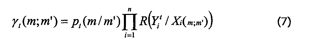
![]()
![]()
![]()
![]()
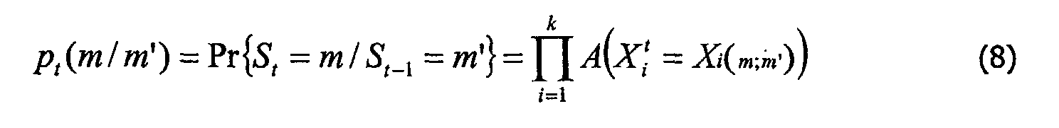
Dans le cas d'utilisation d'une version logarithmique de l'algorithme, tous les produits dans les équations (7) et (8) sont à remplacer par des sommes.When using a logarithmic version of the algorithm, all products in equations (7) and (8) are to be replaced by sums.
L'algorithme Forward-Backward, ou une de ces variantes, est alors appliqué de manière classique, avec les métriques de branche adaptées au cas où les données binaires sont remplacées par des symboles comme décrit par les équations (7) et (8). L'algorithme comporte trois étapes comme dans l'article de L. R. Bahl, J. Cocke, F . Jelinek et J. Raviv :
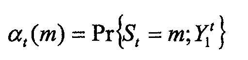
- une passe « aller » qui permet de calculer les
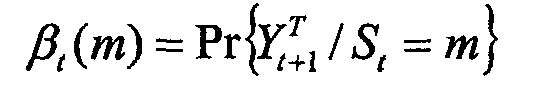
- une passe « retour » qui permet de calculer les
- un calcul, à partir des α, β et γ des σ qui sont des valeurs
proportionnelles aux probabilités a posteriori des transitions :

- a “go” pass which allows you to calculate
- a “return” pass which allows you to calculate the
- a calculation, from α, β and γ of σ which are values proportional to the posterior probabilities of the transitions:
Le calcul des probabilités a posteriori des symboles d'information s'effectue
à partir de ces quantités. Le vecteur de probabilité a posteriori du symbole d'information X t / i
s'écrit :
![]()
![]()
![]()
![]()
Le calcul des informations extrinsèques de chaque symbole d'information
peut se faire parallèlement au calcul des probabilités a posteriori sur le même symbole en
ignorant dans les métriques de branches γt (m,m'), considérées à l'équation (11), les
termes correspondant à la probabilité a priori et à la vraisemblance du symbole
d'information considéré. Le vecteur d'information extrinsèque du symbole d'information X t / i
s'écrit :
![]()

![]()
![]()
![]()
Des opérations de normalisation similaires à l'équation (4) sont effectuées
sur les vecteurs de probabilité a posteriori et sur les vecteurs d'informations extrinsèques :

Il est à noter que la généralisation du décodage à entrée et sortie souple d'un code convolutif binaire, à un code sur les symboles n'entraíne aucune modification de l'algorithme MAP, ou de ses variantes sous-optimales. Il ne s'agit que d'adapter les entrées et les sorties de l'algorithme à des données vectorielles correspondant à toutes les valeurs possibles des symboles. En particulier, les techniques classiques d'initialisation des quantités « alpha » et « beta » de l'algorithme sont valables, qu'il s'agisse d'un codage sans fermeture du treillis, avec forcage à zéro de l'état final, ou d'un codage circulaire (tail-biting en anglais).It should be noted that the generalization of decoding with flexible input and output from a binary convolutional code, to a code on the symbols does not entail any modification of the MAP algorithm, or its sub-optimal variants. It is only a question of adapting the inputs and the outputs of the algorithm to vector data corresponding to all values possible symbols. In particular, conventional techniques for initializing quantities "Alpha" and "beta" of the algorithm are valid, whether it is a coding without closing of the trellis, with forcing to zero of the final state, or of a circular coding (tail-biting in English).
Lors de la première itération de décodage, le premier décodeur SISO ne possède pas d'information sur les probabilités a priori des symboles d'informations. Les vecteurs A t / i sont donc initialisés de la manière suivante :
- cas d'une implantation non-logarithmique :
où M est la cardinalité de l'alphabet des symboles

- cas d'une implantation logarithmique :

- case of a non-logarithmic implantation: where M is the cardinality of the alphabet of symbols
- case of logarithmic implantation:
On a ainsi décrit et illustré à l'aide d'exemples un émetteur, un récepteur, un procédé de codage et un procédé de décodage, un programme d'ordinateur et un signal adaptés à des modulations à grand nombre d'états pour améliorer les performances au niveau du décodage de canal. D'autres exemples de réalisation peuvent aisément être dérivés des exemples décrits sans sortir du cadre de l'invention. En particulier, l'invention n'est pas limitée aux modulations décrites dans les exemples.We have thus described and illustrated with examples a transmitter, a receiver, a coding method and decoding method, computer program and signal suitable for modulations with a large number of states to improve performance at channel decoding level. Other embodiments can easily be derived from the examples described without departing from the scope of the invention. In particular, the invention is not limited to the modulations described in the examples.
Claims (11)
caractérisé en ce que lesdits moyens de codage de canal et de modulation comprennent :
characterized in that said channel coding and modulation means comprise:
caractérisé en ce que lesdits moyens de démodulation et de décodage de canal itératifs comportent :
characterized in that said iterative channel demodulation and decoding means comprise:
Applications Claiming Priority (3)
| Application Number | Priority Date | Filing Date | Title |
|---|---|---|---|
| FR0110249 | 2001-07-31 | ||
| FR0110249A FR2828359A1 (en) | 2001-07-31 | 2001-07-31 | TRANSMITTER, RECEIVER, METHODS, PROGRAM AND SIGNAL SUITABLE FOR MODULATIONS WITH A LARGE NUMBER OF STATES |
| US10/206,028 US20040017857A1 (en) | 2001-07-31 | 2002-07-26 | Transmitter, receiver, methods, program and signal adapted to modulations having a large number of states |
Publications (1)
| Publication Number | Publication Date |
|---|---|
| EP1282254A1 true EP1282254A1 (en) | 2003-02-05 |
Family
ID=32395604
Family Applications (1)
| Application Number | Title | Priority Date | Filing Date |
|---|---|---|---|
| EP02077986A Withdrawn EP1282254A1 (en) | 2001-07-31 | 2002-07-22 | Channel coding and decoding for modulation with large number of states |
Country Status (5)
| Country | Link |
|---|---|
| US (1) | US20040017857A1 (en) |
| EP (1) | EP1282254A1 (en) |
| JP (1) | JP2003124818A (en) |
| CN (1) | CN1400738A (en) |
| FR (1) | FR2828359A1 (en) |
Families Citing this family (10)
| Publication number | Priority date | Publication date | Assignee | Title |
|---|---|---|---|---|
| FR2845227B1 (en) * | 2002-10-01 | 2005-01-14 | Telediffusion De France Tdf | METHOD FOR RECEIVING A MODULE SIGNAL ACCORDING TO A MULTI-LEVEL ENCODING TECHNIQUE, DECODING METHOD, RECEIVING DEVICE, ENCODING-DECODING SYSTEM AND APPLICATIONS THEREOF |
| ATE315853T1 (en) * | 2002-11-15 | 2006-02-15 | Cit Alcatel | DIGITAL SIGNAL PROCESSING RECEIVER AND METHOD OF OPERATING SAME |
| JP4158852B2 (en) * | 2002-11-19 | 2008-10-01 | 富士通テレコムネットワークス株式会社 | Multiple QAM demodulator |
| WO2007145496A1 (en) * | 2006-06-16 | 2007-12-21 | Samsung Electronics Co., Ltd. | Transmission and reception stream processing devices for processing stream coded with coding rate of 1/3, and methods thereof |
| EP2066055A4 (en) * | 2006-09-29 | 2013-01-16 | Fujitsu Ltd | Wireless communication system, transmitter apparatus and receiver apparatus |
| JP4780029B2 (en) * | 2007-05-08 | 2011-09-28 | セイコーエプソン株式会社 | Transmitter, receiver, transmission method, reception method, fixed-length serial burst data transfer system, semiconductor device, and hybrid semiconductor device |
| JP4780030B2 (en) * | 2007-05-08 | 2011-09-28 | セイコーエプソン株式会社 | Transmitter, receiver, transmission method, reception method, variable-length serial burst data transfer system, semiconductor device, and hybrid semiconductor device |
| GB2499270B (en) * | 2012-06-07 | 2014-07-09 | Imagination Tech Ltd | Efficient demapping of constellations |
| CN103516465B (en) * | 2012-06-21 | 2017-04-26 | 华为技术有限公司 | Coded modulation and demodulation and demodulation and decoding method, device and system |
| CN115361062B (en) * | 2022-10-14 | 2023-01-31 | 长春理工大学 | Spatial information processing system and method based on channel state feedback |
Citations (1)
| Publication number | Priority date | Publication date | Assignee | Title |
|---|---|---|---|---|
| DE19934646A1 (en) * | 1999-07-16 | 2001-02-01 | Univ Dresden Tech | Method and device for iterative decoding of chained codes |
Family Cites Families (8)
| Publication number | Priority date | Publication date | Assignee | Title |
|---|---|---|---|---|
| US6606355B1 (en) * | 1997-05-12 | 2003-08-12 | Lucent Technologies Inc. | Channel coding in the presence of bit robbing |
| FI104133B (en) * | 1997-11-28 | 1999-11-15 | Nokia Mobile Phones Ltd | Coding and modulation method and device for its application |
| JP2000068863A (en) * | 1998-08-19 | 2000-03-03 | Fujitsu Ltd | Coder and its method |
| US6891897B1 (en) * | 1999-07-23 | 2005-05-10 | Nortel Networks Limited | Space-time coding and channel estimation scheme, arrangement and method |
| EP1085661B1 (en) * | 1999-09-14 | 2005-03-02 | Lucent Technologies Inc. | Channel decoder and method of channel decoding |
| US6856656B2 (en) * | 2000-12-04 | 2005-02-15 | Conexant Systems, Inc. | Iterative carrier phase tracking decoding system |
| US6885711B2 (en) * | 2001-06-27 | 2005-04-26 | Qualcomm Inc | Turbo decoder with multiple scale selections |
| US7154936B2 (en) * | 2001-12-03 | 2006-12-26 | Qualcomm, Incorporated | Iterative detection and decoding for a MIMO-OFDM system |
-
2001
- 2001-07-31 FR FR0110249A patent/FR2828359A1/en active Pending
-
2002
- 2002-07-22 EP EP02077986A patent/EP1282254A1/en not_active Withdrawn
- 2002-07-26 CN CN02127065A patent/CN1400738A/en active Pending
- 2002-07-26 US US10/206,028 patent/US20040017857A1/en not_active Abandoned
- 2002-07-31 JP JP2002222709A patent/JP2003124818A/en not_active Withdrawn
Patent Citations (1)
| Publication number | Priority date | Publication date | Assignee | Title |
|---|---|---|---|---|
| DE19934646A1 (en) * | 1999-07-16 | 2001-02-01 | Univ Dresden Tech | Method and device for iterative decoding of chained codes |
Non-Patent Citations (4)
| Title |
|---|
| BAUCH G ET AL: "ITERATIVE EQUALIZATION AND DECODING IN MOBILE COMMUNICATIONS SYSTEMS", PROCEEDINGS OF EUROPEAN PERSONAL AND MOBILE COMMUNICATIONS CONFERENCE, XX, XX, 30 September 1997 (1997-09-30), pages 307 - 312, XP002060630 * |
| BENEDETTO S ET AL: "A SOFT-INPUT SOFT-OUTPUT APP MODULE FOR ITERATIVE DECODING OF CONCATENATED CODES", IEEE COMMUNICATIONS LETTERS, IEEE SERVICE CENTER, PISCATAWAY,US, US, vol. 1, no. 1, 1997, pages 22 - 24, XP000643017, ISSN: 1089-7798 * |
| BENEDETTO S ET AL: "SOFT-INPUT SOFT-OUTPUT MODULES FOR THE CONSTRUCTION AND DISTRIBUTED ITERATIVE DECODING OF CODE NETWORKS", EUROPEAN TRANSACTIONS ON TELECOMMUNICATIONS, EUREL PUBLICATION, MILANO, IT, vol. 9, no. 2, 1 March 1998 (1998-03-01), pages 155 - 172, XP000751912, ISSN: 1124-318X * |
| TEN BRINK S ET AL: "Iterative demapping for QPSK modulation", ELECTRONICS LETTERS, IEE STEVENAGE, GB, vol. 34, no. 15, 23 July 1998 (1998-07-23), pages 1459 - 1460, XP006010100, ISSN: 0013-5194 * |
Also Published As
| Publication number | Publication date |
|---|---|
| FR2828359A1 (en) | 2003-02-07 |
| CN1400738A (en) | 2003-03-05 |
| JP2003124818A (en) | 2003-04-25 |
| US20040017857A1 (en) | 2004-01-29 |
Similar Documents
| Publication | Publication Date | Title |
|---|---|---|
| EP1388945A2 (en) | Soft decision output decoder for decoding convolutionally encoded codewords | |
| EP0897224A2 (en) | Method of enhanced max-log-a posteriori probability processing | |
| FR2815199A1 (en) | Cyclic turbo coding scheme improves minimum Hamming distance | |
| Jeanne et al. | Joint source-channel decoding of variable-length codes for convolutional codes and turbo codes | |
| FR2808632A1 (en) | TURBO-DECODING METHOD WITH RE-ENCODING OF ERRONEOUS INFORMATION AND FEEDBACK | |
| FR2804260A1 (en) | DIGITAL CORRECTIVE ERROR-TYPE CODING TRANSMITTING METHOD | |
| FR2747255A1 (en) | METHOD AND DEVICE FOR CONVOLUTIVE CODING OF DATA BLOCKS, AND CORRESPONDING DECODING METHOD AND DEVICE | |
| EP1282968A1 (en) | Method and system for detecting and iterative decoding of received symbols, coupled with reevaluation of transmission channel coefficients | |
| EP1230736B1 (en) | Method for decoding data coded with an entropic code, corresponding decoding device and transmission system | |
| WO2005101668A1 (en) | Joint source-channel decoding method and associated joint source-channel decoder | |
| EP1128589B1 (en) | Interruption criterion for a turbo decoder | |
| EP1282254A1 (en) | Channel coding and decoding for modulation with large number of states | |
| FR2807237A1 (en) | METHOD AND DEVICE FOR ASSESSING THE NOISE ASSOCIATED WITH TURBOCODES, AND SYSTEMS USING THE SAME | |
| FR2782425A1 (en) | ERROR CORRECTING ENCODING METHOD AND DEVICE AND METHOD AND CORRESPONDING DECODING DEVICE | |
| FR2807895A1 (en) | Methods and devices for coding and decoding and systems implementing them, for use in protected wireless communications | |
| JP2002535910A (en) | Decoding method and decoding device for convolutional code | |
| FR2802735A1 (en) | Coding/decoding digital word mechanism having padding providing polynomial division with interspersion sequence/second padding operation and recursive coding operation output | |
| EP1128588A1 (en) | Method of error correcting coding-type digital transmission comprising a step of puncturing scheme selection | |
| FR2806177A1 (en) | DIGITAL CORRECTIVE ERROR-TYPE CODING TRANSMITTING METHOD | |
| FR2850810A1 (en) | METHOD FOR CONTROLLING THE NUMBER OF ITERATIONS OF AN ITERATIVE DECODING PROCESS AND DEVICE FOR IMPLEMENTING THE METHOD | |
| FR2800941A1 (en) | Digital code decoding technique uses decoding lattice based on binary tree structure for reduced error rate decoding | |
| Shoup | Hardware implementation of a high-throughput 64-PPM serial concatenated turbo decoder | |
| Bokolamulla et al. | Reduced complexity iterative decoding for concatenated coding schemes | |
| KR20030013275A (en) | Transmitter, receiver, methods, program and signal adapted to modulations having a large number of states | |
| FR2804556A1 (en) | Turbocoder with maximum similarity decoder having first decoder operation providing elementary code bits/minimising and symbol error factor then second decoding using maximum similarity algorithm. |
Legal Events
| Date | Code | Title | Description |
|---|---|---|---|
| PUAI | Public reference made under article 153(3) epc to a published international application that has entered the european phase |
Free format text: ORIGINAL CODE: 0009012 |
|
| AK | Designated contracting states |
Designated state(s): AT BE BG CH CY CZ DE DK EE ES FI FR GB GR IE IT LI LU MC NL PT SE SK TR |
|
| AX | Request for extension of the european patent |
Extension state: AL LT LV MK RO SI |
|
| 17P | Request for examination filed |
Effective date: 20030805 |
|
| AKX | Designation fees paid |
Designated state(s): AT BE BG CH CY CZ DE DK EE ES FI FR GB GR IE IT LI LU MC NL PT SE SK TR |
|
| 17Q | First examination report despatched |
Effective date: 20031223 |
|
| GRAP | Despatch of communication of intention to grant a patent |
Free format text: ORIGINAL CODE: EPIDOSNIGR1 |
|
| STAA | Information on the status of an ep patent application or granted ep patent |
Free format text: STATUS: THE APPLICATION IS DEEMED TO BE WITHDRAWN |
|
| 18D | Application deemed to be withdrawn |
Effective date: 20051115 |