EP1282018A1 - A wearable electronic device - Google Patents
A wearable electronic device Download PDFInfo
- Publication number
- EP1282018A1 EP1282018A1 EP01306689A EP01306689A EP1282018A1 EP 1282018 A1 EP1282018 A1 EP 1282018A1 EP 01306689 A EP01306689 A EP 01306689A EP 01306689 A EP01306689 A EP 01306689A EP 1282018 A1 EP1282018 A1 EP 1282018A1
- Authority
- EP
- European Patent Office
- Prior art keywords
- user
- cursor
- control
- electronic device
- wearable electronic
- Prior art date
- Legal status (The legal status is an assumption and is not a legal conclusion. Google has not performed a legal analysis and makes no representation as to the accuracy of the status listed.)
- Withdrawn
Links
Images


Classifications
-
- G—PHYSICS
- G04—HOROLOGY
- G04G—ELECTRONIC TIME-PIECES
- G04G21/00—Input or output devices integrated in time-pieces
Definitions
- the present invention relates to a wearable electronic device especially, but not exclusively, a wristwatch.
- wristwatches have been extended and now wristwatches are available which, as well as telling the time, can, for example, record heart rate, show position globally, play music, synchronise with an organiser and store passwords.
- wristwatches By their very nature, wristwatches impose significant size and style constraints with respect to the user interface.
- the availability of small-area, high-resolution LCD displays, batteries with longer life, and faster and smaller microprocessors is likely to encourage the development of more complex applications where more intensive user interaction is required.
- the present invention has an aim of facilitating more intensive user interaction with a wearable device, especially, but not exclusively a wristwatch, without violating size and style constraints.
- the present invention may provide a wearable electronic device, comprising:
- a cursor control means being responsive to a control stimulus acting in a cursor control area remote from the base, the size of the wearable electronic device and the control area by which it's user interface is controlled are made substantially independent from one another.
- the cursor control means further allows the user to signal a selection operation.
- the control stimulus from the user may be in the form of the user's finger or other another pointing device wielded by the user.
- the wearable electronic device further comprises a touch panel.
- the touch panel provides a control signal to the cursor control means indicative of the position of a control stimulus in the form of contact from a user's finger.
- the control signal provides an absolute indication of the position of the control stimulus within the control area.
- the control area preferably amounts to substantially the whole area of the touch panel.
- the touch panel is moveable from a closed position in a direction away from the base to an open position in which the user can operate the touch panel.
- the wearable electronic device further comprises transceiver means for transmitting and receiving infrared signals.
- the transceiver means provides a control signal to the cursor control means indicative of the position of a control stimulus in the control area in the form of the presence of a user's finger.
- the transceiver means generates the control signal by analysing the characteristics of a signal which it transmits after reflection from the user's finger.
- the control signal provides an absolute indication of the position of the control stimulus within the control area.
- the wearable electronic device further comprises a finger-operated optical mouse.
- the wearable electronic device further comprises transceiver means for transmitting and receiving optical signals.
- the transceiver means provides a control signal to the cursor control means indicative of the orientation of the optical mouse.
- the transceiver means generates the control signal by analysing the characteristics of a signal which it transmits after reflection from the back of the user's hand in the control area.
- the control signal provides an indication of the desired position of the cursor relative to the current position.
- the cursor control area may comprise an area on, or closely adjacent to the user's body, directly acting on the user's skin or perhaps indirectly acting on the user's skin, for example, via clothing.
- the electronic device is worn as a wristwatch.
- the term 'cursor' should be understood in its broad sense so as to not only include a characteristic mark or character which serves to indicate the current point of user interaction with the contents of the display, but also other ways of indicating the current point of user interaction with the contents of the display, such as, for example, the highlighting of a small, defined portion of the contents of the display, thereby indicating the current point of user interaction.
- the present invention may provide a method for controlling the cursor of a wearable electronic device having a display by sensing a control stimulus from the user acting in a cursor control area remote from the display in an area on or closely adjacent to the user's body.
- a wearable wristwatch in accordance with a first embodiment of the invention is depicted in Figure 1 and generally designated 10.
- the wristwatch comprises a base 12 to which is mounted a transparent touch panel 14 by a hinge 16.
- the touch panel 14 can be moved from the closed position of Figure 1 to an open position as in Figure 2, in which a display 18 mounted to the base 12 is exposed.
- a microswitch 20 in the base 12 is depressed when touch panel 14 adopts its open, Figure 2 position.
- the touch panel 14 may not be transparent, but may include a secondary display which is upward facing when the panel 14 is in the closed position and which duplicates the contents of the display 18.
- Control circuitry 50 illustrated in Figure 3, is located inside the base 12 for controlling the operation of the wristwatch 10.
- the control circuitry 50 comprises a control processor 52 which coordinates the overall operation of the wristwatch 10, drives the display 18, and is connected to a time-keeping module 54 dedicated to keeping accurate time; an RF module 56 providing two-way radio communication, preferably with a cellular system; and a user input module 58 which processes cursor control signals from the user and sends them to the control processor 52.
- the user input module 58 is coupled to the touch panel 14.
- Figures 4(a) and 4(b) show the electrical connection 22 between the touch panel 14 and the control circuitry 50.
- the base 12 is fastened to a user's wrist in a conventional manner using a band or strap 24.
- the touch panel 14 when the touch panel 14 is in its open position as in Figure 5, the back of the user's hand plays no significant role in supporting the touch panel 14 when it is in it's open position due to the structure of the hinge, although there might be contact or occasional contact between the touch panel 14 and the back of the user's hand.
- the structure of the hinge may be such that the back of the user's hand fully supports the touch panel 14 when in it's open position. To move the cursor 60 around the display 18, the user simply moves his finger lightly around the touch panel 14.
- the pressure from the user's finger causes localised flexing of the outer casing of the touch panel 14, whereby a region of the outer casing is depressed inwardly and this depression is registered by a small region of the array of sensors therein.
- the sensors within the touch panel 14 thus generate a set of signals indicative of the position of the depression/user's finger, which signals are received by the user input module 58 and analysed.
- the user input module 58 analyses the signals to determine whether they correspond to a small amount of applied pressure, whereby the cluster of sensors detecting the depression is small, or whether the signals correspond to higher applied pressure, whereby the cluster of sensors detecting the depression is relatively large.
- the user input module 58 In the case when the applied pressure is light, the user input module 58 translates those signals into screen position data which is sent to the control processor 52. The control processor 52 updates the position of the cursor 60 on the display 18. In the case, when the applied pressure is higher, the user input module 58 interprets this as a 'selection' operation on the part of the user and conveys that information to the control processor.
- the wristwatch 10 has loaded down over the air a page containing an update on the current news from a WAP/I- mode site or other internet source.
- a clock graphic 62 driven by the time-keeping module 54 is shown.
- the new update contains various highlighted portions 64, which designate the presence of links to other pages of information.
- the user can manoeuvre the cursor 60 around the display 18 by moving his finger around the touch panel 18, while applying light pressure.
- Figure 14 illustrates the advantage of the first embodiment of the invention over a conventional touch screen approach.
- the first embodiment of the present invention by providing a cursor control area 15, i.e. the touch panel 14, in which the user's finger may roam, the user's view of the display 18 and the cursor 60 is completed unimpeded.
- a cursor control area i.e. the touch panel 14
- the user's view of the display 18 and the cursor 60 is completed unimpeded.
- the user wishes to access another page of information, he simply manoeuvres the cursor 60 until it sits on the highlighted portion 64 related to the desired information and applies a firm depression.
- the firm depression generates a signal in a relatively large amount of sensors within the touch panel 14.
- the user input module 58 analyses those signals from the sensors and recognises that the user is making a selection and conveys this information to the control processor 52.
- the control processor 52 thus then downloads over the air the page of information related to the selected link and then the user can continue to access content.
- the operation of the user simply manoeuvring the cursor and making a selection operation can be distinguished not by the amount of applied pressure as described above, but by a clicking operation where the applied pressure is momentarily released and then re-applied at approximately the same location.
- a wearable wristwatch in accordance with a second embodiment of the invention is depicted in Figure 7 and generally designated 30. Where a part of the second embodiment is similar to a corresponding part in the first embodiment, the same reference numeral is hereinafter used.
- the second embodiment differs from the first embodiment in that an infrared transceiver unit 32 is used as an input transducer for the user and thus should be understood as taking the place of the touch panel 14 in Figure 3.
- the transceiver unit 32 comprises an infrared transmission source 32a and an array of infrared detectors 32b.
- the base 12 is fastened to a user's wrist in a conventional manner using a band or strap 24.
- the transmission source 32a continuously transmits (see Figure 8(a)) an infrared signal which is reflected by the user's finger.
- the reflected signal (see Figure 8(b)) is detected by the array of detectors 32b.
- the user input module 58 analyses the signals from the detectors and translates those signals into screen position data which is sent to the control processor 52.
- the control processor 52 updates the position of the cursor 60 on the display 18.
- the infrared energy coming from the transmission source 32a is highly directional and confined largely to a narrow beam parallel to the surface of the user's hand.
- the user momentarily lifts his finger vertically out of the plane of the which the infrared signal occupies and then replaces it at approximately the same location as indicated by the arrow X in Figure 9.
- the fluctuation in the reflected signal which this action produces is recognised by the user input module 58 as selection.
- the user can download to the wristwatch 30 over the air a page containing an update on the current news from a WAP/I- mode site or other internet source.
- the user can manoeuvre the cursor 60 around the display 18 by moving his finger around the control area 15.
- Figure 14 illustrates the advantage of the second embodiment of the invention over a conventional touch screen approach.
- the second embodiment of the present invention by providing a cursor control area 15 in which the user's finger may roam, the user's view of the display 18 and the cursor 60 is completed unimpeded.
- the user can lay his finger immediately adjacent all the infra detectors 32b and this is interpreted by the control processor 52 to put the transceiver unit 32 into a power-saving mode, whereby the time gap between transmissions of the transceiver is greatly increased.
- the transceiver can be brought into normal operational mode, whereby the time gap between transmissions is greatly reduced.
- a switch on the base 12 can be used to turn the transceiver unit 32 on and off.
- a wearable wristwatch in accordance with a third embodiment of the invention is depicted in Figure 10 and generally designated 40. Where a part of the first embodiment is similar to a corresponding part in the first or second embodiments, the same reference numeral is hereinafter used.
- the second embodiment differs from the first and second embodiments in that an optical mouse 42 is used as an input transducer for the user and thus should be understood as taking the place of the touch panel 14 in Figure 3.
- the optical mouse 42 comprises a cradle 44 for receiving and retaining a finger of the user.
- the cradle 44 is in the form of an annulus with a portion cut away, thereby defining two arms 44a and 44b, to allow the passage of the user's finger through the cut-away portion whereby the user's finger can rest therein with the major axis of the user's finger perpendicular to the plane of the annulus.
- the cut-away portion preferably extends less than 180 degrees around the circumference of the annulus to facilitate the retention of the user's finger within the cradle 44.
- three sets of optical transmitter and receiver pairs are located within the cradle 44.
- the transmitters 45a,b,c are located in one arm 44a of the cradle and the corresponding receivers 46a,b,c are located in the other arm 44b.
- a connecting cable 48 physically and electrically connects the cradle to the rest of the wristwatch 40.
- a switch 49 is located on the inner wall of the cradle at a position above the windows 47a,b,c.
- the base 12 is fastened to a user's wrist in a conventional manner using a band or strap 24.
- the optical mouse 42 can be pulled by the user from a storage position as shown in Figure 11(a) to an operational positional as shown in Figure 11(b).
- a cable supply mechanism is located inside the wristwatch 40 and is not shown in the drawings. The cable supply mechanism supplies a bias to the cable 48 which the user has to overcome in order to pull the cable to the Figure 11(b) position. In the absence of the user's finger, the bias applied by the cable supply mechanism pulls the optical mouse 42 back to it's Figure 11(a) position.
- the transmitters 45a,b,c continuously transmits a signal at the respective window 47a,b,c which is reflected by the user's hand and received by the respective receivers 46a,b,c.
- the cradle 44 is rolled about an axis perpendicular to a major plane of the cradle 44 i.e. as indicated by the arrow Y, whereby the portion of its outer surface which directly contacts the back of the user's hand changes, the area of the windows 47a,b,c which is immediately adjacent the user's hand also changes and hence the reflected signal received by the respective receiver 46a,b,c also changes correspondingly.
- the degree to which the cradle has been rolled i.e.
- the cradle 44 is rocked to and from about an axis perpendicular to the axis of the above-mentioned rolling axis, then the relative position of the receiver/transmitter pair 45a,46a and the receiver/transmitter pair 45c,46c relative to the back of the user's hand varies. In this way, the degree to which the cradle 44 has been rocked can be determined.
- the user input module 58 analyses the signals from the receivers 46a,b,c and translates those signals into degrees of rock and roll and send this data to the control processor 52.
- the control processor 52 moves the position of the cursor 60 on the display 18 from its current position to a new position specified by the rock and roll data.
- the cursor position remains the same.
- a cursor control area 15 is shown, but it will appreciated that the boundaries of this cursor control area are more a mental construct for the benefit of the user than physical boundaries, since from the foregoing description it will be apparent that the cursor position is controlled by the orientation of the cradle 44 relative to a reflecting surface, like the back of the user's hand, rather than an absolute position within the cursor control area.
- the user In order to make a selection, the user must firmly depress his finger to actuate the switch 49, which actuation is communicated to the user input module 58.
- the switch 49 protrudes clearly from the inner surface of the cradle, in practice, the switch 49 would hardly stand proud of the inner surface 44 at all or perhaps be slightly recessed so as to ensure that only a conscious and deliberate application of pressure by the user caused its actuation.
- the user can download to the wristwatch 40 over the air a page containing an update on the current news from a WAP/I- mode site or other internet source.
- the mouse 42 With the mouse 42 in its withdrawn position and occupying the cursor control area 15, the user can manoeuvre the cursor 60 around the display 18 by rocking and rolling his finger as described above for the appropriate duration of time.
- Figure 14 illustrates the advantage of the third embodiment of the invention over a conventional touch screen approach. Because the size of the user's finger is relatively large in relation to the overall size of the display 18, manoeuvring of the cursor tends to obscure most of the display, thereby adversely affecting the manoeuvrability of the cursor 60 and generally inconveniencing the user.
- the third embodiment of the present invention by providing a cursor control area 15 remote from the display 18, the user's view of the display 18 and the cursor 60 is completed unimpeded.
- the user wishes to access another page of information, he simply manoeuvres the cursor 60 until it sits over a link related to the desired information and then actuates the switch 49 which actuation is communicated, via the user input module 58, to the control processor 52.
- the control processor 52 thus then downloads over the air the page of information related to the selected link and then the user can continue to access content.
- the functionality of the user input module 58 can be implemented in software within the control processor 52.
Abstract
A wearable electronic device, comprising a base, a display mounted to the
base, a user-controllable cursor, cursor control means for allowing the user to
control the position of the cursor on the display, wherein the cursor control
means is responsive to a control stimulus from the user acting in a cursor
control area remote from the base.
Description
- The present invention relates to a wearable electronic device especially, but not exclusively, a wristwatch.
- The functionality of wristwatches has been extended and now wristwatches are available which, as well as telling the time, can, for example, record heart rate, show position globally, play music, synchronise with an organiser and store passwords.
- By their very nature, wristwatches impose significant size and style constraints with respect to the user interface. The availability of small-area, high-resolution LCD displays, batteries with longer life, and faster and smaller microprocessors is likely to encourage the development of more complex applications where more intensive user interaction is required. The present invention has an aim of facilitating more intensive user interaction with a wearable device, especially, but not exclusively a wristwatch, without violating size and style constraints.
- With this in mind, according to one aspect, the present invention may provide a wearable electronic device, comprising:
- a base;
- a display mounted to the base;
- a user-controllable cursor; and
- cursor control means for allowing the user to control the position of the cursor on the display, wherein the cursor control means is responsive to a control stimulus from the user acting in a cursor control area remote from the base.
-
- Thus, by the provision of a cursor control means being responsive to a control stimulus acting in a cursor control area remote from the base, the size of the wearable electronic device and the control area by which it's user interface is controlled are made substantially independent from one another.
- Preferably, the cursor control means further allows the user to signal a selection operation.
- The control stimulus from the user may be in the form of the user's finger or other another pointing device wielded by the user.
- In a first embodiment, the wearable electronic device further comprises a touch panel. The touch panel provides a control signal to the cursor control means indicative of the position of a control stimulus in the form of contact from a user's finger. The control signal provides an absolute indication of the position of the control stimulus within the control area. The control area preferably amounts to substantially the whole area of the touch panel.
- Preferably, the touch panel is moveable from a closed position in a direction away from the base to an open position in which the user can operate the touch panel.
- In a second embodiment, the wearable electronic device further comprises transceiver means for transmitting and receiving infrared signals. The transceiver means provides a control signal to the cursor control means indicative of the position of a control stimulus in the control area in the form of the presence of a user's finger. The transceiver means generates the control signal by analysing the characteristics of a signal which it transmits after reflection from the user's finger. The control signal provides an absolute indication of the position of the control stimulus within the control area.
- In a third embodiment, the wearable electronic device further comprises a finger-operated optical mouse. The wearable electronic device further comprises transceiver means for transmitting and receiving optical signals. The transceiver means provides a control signal to the cursor control means indicative of the orientation of the optical mouse. The transceiver means generates the control signal by analysing the characteristics of a signal which it transmits after reflection from the back of the user's hand in the control area. The control signal provides an indication of the desired position of the cursor relative to the current position.
- The cursor control area may comprise an area on, or closely adjacent to the user's body, directly acting on the user's skin or perhaps indirectly acting on the user's skin, for example, via clothing.
- In a preferred embodiment of the invention, the electronic device is worn as a wristwatch.
- In the context of the present invention, the term 'cursor' should be understood in its broad sense so as to not only include a characteristic mark or character which serves to indicate the current point of user interaction with the contents of the display, but also other ways of indicating the current point of user interaction with the contents of the display, such as, for example, the highlighting of a small, defined portion of the contents of the display, thereby indicating the current point of user interaction.
- According to another aspect, the present invention may provide a method for controlling the cursor of a wearable electronic device having a display by sensing a control stimulus from the user acting in a cursor control area remote from the display in an area on or closely adjacent to the user's body.
- Exemplary embodiments of the invention are hereinafter described with reference to the accompany drawings, in which:
- Figure 1 show a view of a first embodiment of the invention in a closed position;
- Figure 2 show a view of the first embodiment in an open position;
- Figure 3 shows schematically control circuitry of the first embodiment;
- Figures 4(a) and 4(b) show exploded views of Figure 2;
- Figure 5 shows the first embodiment in use mounted to the wrist of a user;
- Figure 6 shows a more detailed view of the first embodiment in use, as in Figure 5, with parts removed;
- Figure 7 shows a second embodiment of the invention in used mounted to the wrist of a user;
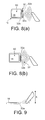
- Figures 8(a) and 8(b) illustrate the principle of operation of the second embodiment;
- Figure 9 shows a side view of Figure 8(a);
- Figure 10 shows a third embodiment of the invention in use mounted to the wrist of a user;
- Figures 11(a) and 11(b) show a side view of the third embodiment in a docked and operational condition;
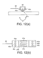
- Figures 12(a) and 12(b) illustrate the principle of operation of the optical mouse of the third embodiment;
- Figure 13 shows a more detailed view of the third embodiment in use, as in Figure 10, with parts removed; and
- Figure 14 illustrates an advantage of the first, second and third embodiments of the invention.
-
- A wearable wristwatch in accordance with a first embodiment of the invention is depicted in Figure 1 and generally designated 10. The wristwatch comprises a
base 12 to which is mounted atransparent touch panel 14 by ahinge 16. Thetouch panel 14 can be moved from the closed position of Figure 1 to an open position as in Figure 2, in which adisplay 18 mounted to thebase 12 is exposed. Amicroswitch 20 in thebase 12 is depressed whentouch panel 14 adopts its open, Figure 2 position. - In other embodiments (not shown), the
touch panel 14 may not be transparent, but may include a secondary display which is upward facing when thepanel 14 is in the closed position and which duplicates the contents of thedisplay 18. -
Control circuitry 50, illustrated in Figure 3, is located inside thebase 12 for controlling the operation of thewristwatch 10. Thecontrol circuitry 50 comprises acontrol processor 52 which coordinates the overall operation of thewristwatch 10, drives thedisplay 18, and is connected to a time-keeping module 54 dedicated to keeping accurate time; anRF module 56 providing two-way radio communication, preferably with a cellular system; and auser input module 58 which processes cursor control signals from the user and sends them to thecontrol processor 52. In this embodiment, theuser input module 58 is coupled to thetouch panel 14. Figures 4(a) and 4(b) show theelectrical connection 22 between thetouch panel 14 and thecontrol circuitry 50. - Referring to Figure 5, in use, the
base 12 is fastened to a user's wrist in a conventional manner using a band orstrap 24. In this embodiment, when thetouch panel 14 is in its open position as in Figure 5, the back of the user's hand plays no significant role in supporting thetouch panel 14 when it is in it's open position due to the structure of the hinge, although there might be contact or occasional contact between thetouch panel 14 and the back of the user's hand. In other embodiments, the structure of the hinge may be such that the back of the user's hand fully supports thetouch panel 14 when in it's open position. To move thecursor 60 around thedisplay 18, the user simply moves his finger lightly around thetouch panel 14. The pressure from the user's finger causes localised flexing of the outer casing of thetouch panel 14, whereby a region of the outer casing is depressed inwardly and this depression is registered by a small region of the array of sensors therein. The sensors within thetouch panel 14 thus generate a set of signals indicative of the position of the depression/user's finger, which signals are received by theuser input module 58 and analysed. Theuser input module 58 analyses the signals to determine whether they correspond to a small amount of applied pressure, whereby the cluster of sensors detecting the depression is small, or whether the signals correspond to higher applied pressure, whereby the cluster of sensors detecting the depression is relatively large. In the case when the applied pressure is light, theuser input module 58 translates those signals into screen position data which is sent to thecontrol processor 52. Thecontrol processor 52 updates the position of thecursor 60 on thedisplay 18. In the case, when the applied pressure is higher, theuser input module 58 interprets this as a 'selection' operation on the part of the user and conveys that information to the control processor. - In Figure 6, the
wristwatch 10 has loaded down over the air a page containing an update on the current news from a WAP/I- mode site or other internet source. In the top right hand corner of thedisplay 18, a clock graphic 62, driven by the time-keeping module 54 is shown. The new update contains various highlighted portions 64, which designate the presence of links to other pages of information. The user can manoeuvre thecursor 60 around thedisplay 18 by moving his finger around thetouch panel 18, while applying light pressure. Figure 14 illustrates the advantage of the first embodiment of the invention over a conventional touch screen approach. Because the size of the user's finger is relatively large in relation to the overall size of thedisplay 18, manoeuvring of the cursor tends to obscure most of the display, thereby adversely affecting the manoeuvrability of thecursor 60 and generally inconveniencing the user. In contrast, the first embodiment of the present invention by providing acursor control area 15, i.e. thetouch panel 14, in which the user's finger may roam, the user's view of thedisplay 18 and thecursor 60 is completed unimpeded. When the user wishes to access another page of information, he simply manoeuvres thecursor 60 until it sits on the highlighted portion 64 related to the desired information and applies a firm depression. The firm depression generates a signal in a relatively large amount of sensors within thetouch panel 14. In this case, theuser input module 58 analyses those signals from the sensors and recognises that the user is making a selection and conveys this information to thecontrol processor 52. Thecontrol processor 52 thus then downloads over the air the page of information related to the selected link and then the user can continue to access content. - In another embodiment, the operation of the user simply manoeuvring the cursor and making a selection operation can be distinguished not by the amount of applied pressure as described above, but by a clicking operation where the applied pressure is momentarily released and then re-applied at approximately the same location.
- A wearable wristwatch in accordance with a second embodiment of the invention is depicted in Figure 7 and generally designated 30. Where a part of the second embodiment is similar to a corresponding part in the first embodiment, the same reference numeral is hereinafter used. The second embodiment differs from the first embodiment in that an
infrared transceiver unit 32 is used as an input transducer for the user and thus should be understood as taking the place of thetouch panel 14 in Figure 3. Thetransceiver unit 32 comprises aninfrared transmission source 32a and an array ofinfrared detectors 32b. - Referring to Figure 7, in use, the
base 12 is fastened to a user's wrist in a conventional manner using a band orstrap 24. To move thecursor 60 around thedisplay 18, the user slides his finger around the back of his other hand, bearing thewristwatch 30, as shown. Thetransmission source 32a continuously transmits (see Figure 8(a)) an infrared signal which is reflected by the user's finger. The reflected signal (see Figure 8(b)) is detected by the array ofdetectors 32b. Theuser input module 58 analyses the signals from the detectors and translates those signals into screen position data which is sent to thecontrol processor 52. Thecontrol processor 52 updates the position of thecursor 60 on thedisplay 18. It will noted that the infrared energy coming from thetransmission source 32a is highly directional and confined largely to a narrow beam parallel to the surface of the user's hand. In order to perform a 'selection' operation, the user momentarily lifts his finger vertically out of the plane of the which the infrared signal occupies and then replaces it at approximately the same location as indicated by the arrow X in Figure 9. The fluctuation in the reflected signal which this action produces is recognised by theuser input module 58 as selection. - Referring to Figure 7, as with the first embodiment, the user can download to the
wristwatch 30 over the air a page containing an update on the current news from a WAP/I- mode site or other internet source. The user can manoeuvre thecursor 60 around thedisplay 18 by moving his finger around thecontrol area 15. Figure 14 illustrates the advantage of the second embodiment of the invention over a conventional touch screen approach. - Because the size of the user's finger is relatively large in relation to the overall size of the
display 18, manoeuvring of the cursor tends to obscure most of the display, thereby adversely affecting the manoeuvrability of thecursor 60 and generally inconveniencing the user. In contrast, the second embodiment of the present invention by providing acursor control area 15 in which the user's finger may roam, the user's view of thedisplay 18 and thecursor 60 is completed unimpeded. When the user wishes to access another page of information, he simply manoeuvres thecursor 60 until it sits over a link (not shown in Figure 7) related to the desired information and momentarily vertically lifts his finger out of the path of the infrared signal from thetransmission source 32a and then replaces it at approximately the same location. The fluctuation in the reflected signal which this action produces is recognised by theuser input module 58 as selection and conveys this information to thecontrol processor 52. Thecontrol processor 52 thus then downloads over the air the page of information related to the selected link and then the user can continue to access content. - In order to place the
transceiver unit 32 into a power-saving mode, the user can lay his finger immediately adjacent all theinfra detectors 32b and this is interpreted by thecontrol processor 52 to put thetransceiver unit 32 into a power-saving mode, whereby the time gap between transmissions of the transceiver is greatly increased. By performing a similar operation, the transceiver can be brought into normal operational mode, whereby the time gap between transmissions is greatly reduced. In alternative embodiments, a switch on the base 12 can be used to turn thetransceiver unit 32 on and off. - A wearable wristwatch in accordance with a third embodiment of the invention is depicted in Figure 10 and generally designated 40. Where a part of the first embodiment is similar to a corresponding part in the first or second embodiments, the same reference numeral is hereinafter used. The second embodiment differs from the first and second embodiments in that an
optical mouse 42 is used as an input transducer for the user and thus should be understood as taking the place of thetouch panel 14 in Figure 3. Theoptical mouse 42 comprises acradle 44 for receiving and retaining a finger of the user. Thecradle 44 is in the form of an annulus with a portion cut away, thereby defining two arms 44a and 44b, to allow the passage of the user's finger through the cut-away portion whereby the user's finger can rest therein with the major axis of the user's finger perpendicular to the plane of the annulus. The cut-away portion preferably extends less than 180 degrees around the circumference of the annulus to facilitate the retention of the user's finger within thecradle 44. Within thecradle 44, three sets of optical transmitter and receiver pairs are located. Thetransmitters 45a,b,c are located in one arm 44a of the cradle and thecorresponding receivers 46a,b,c are located in the other arm 44b. In the region intermediate of thetransmitters 45a,b,c andreceivers 46a,b,c,windows 47a,b,c are respectively located. A connectingcable 48 physically and electrically connects the cradle to the rest of thewristwatch 40. Aswitch 49 is located on the inner wall of the cradle at a position above thewindows 47a,b,c. - Referring to Figure 10, in use, the
base 12 is fastened to a user's wrist in a conventional manner using a band orstrap 24. Theoptical mouse 42 can be pulled by the user from a storage position as shown in Figure 11(a) to an operational positional as shown in Figure 11(b). A cable supply mechanism is located inside thewristwatch 40 and is not shown in the drawings. The cable supply mechanism supplies a bias to thecable 48 which the user has to overcome in order to pull the cable to the Figure 11(b) position. In the absence of the user's finger, the bias applied by the cable supply mechanism pulls theoptical mouse 42 back to it's Figure 11(a) position. - Referring to Figure 12(a), the
transmitters 45a,b,c continuously transmits a signal at therespective window 47a,b,c which is reflected by the user's hand and received by therespective receivers 46a,b,c. If thecradle 44 is rolled about an axis perpendicular to a major plane of thecradle 44 i.e. as indicated by the arrow Y, whereby the portion of its outer surface which directly contacts the back of the user's hand changes, the area of thewindows 47a,b,c which is immediately adjacent the user's hand also changes and hence the reflected signal received by therespective receiver 46a,b,c also changes correspondingly. In this way, the degree to which the cradle has been rolled (i.e. along a line parallel to the arrow Y) can be determined. If thecradle 44 is rocked to and from about an axis perpendicular to the axis of the above-mentioned rolling axis, then the relative position of the receiver/transmitter pair transmitter pair cradle 44 has been rocked can be determined. Theuser input module 58 analyses the signals from thereceivers 46a,b,c and translates those signals into degrees of rock and roll and send this data to thecontrol processor 52. Thecontrol processor 52 moves the position of thecursor 60 on thedisplay 18 from its current position to a new position specified by the rock and roll data. When thecradle 44 is in a neutral position, the cursor position remains the same. Referring to Figure 10, in common with the first and second embodiments acursor control area 15 is shown, but it will appreciated that the boundaries of this cursor control area are more a mental construct for the benefit of the user than physical boundaries, since from the foregoing description it will be apparent that the cursor position is controlled by the orientation of thecradle 44 relative to a reflecting surface, like the back of the user's hand, rather than an absolute position within the cursor control area. In order to make a selection, the user must firmly depress his finger to actuate theswitch 49, which actuation is communicated to theuser input module 58. Although for diagrammatic clarity, theswitch 49 protrudes clearly from the inner surface of the cradle, in practice, theswitch 49 would hardly stand proud of theinner surface 44 at all or perhaps be slightly recessed so as to ensure that only a conscious and deliberate application of pressure by the user caused its actuation. - Referring to Figure 13, as with the first and second embodiments, the user can download to the
wristwatch 40 over the air a page containing an update on the current news from a WAP/I- mode site or other internet source. With themouse 42 in its withdrawn position and occupying thecursor control area 15, the user can manoeuvre thecursor 60 around thedisplay 18 by rocking and rolling his finger as described above for the appropriate duration of time. Figure 14 illustrates the advantage of the third embodiment of the invention over a conventional touch screen approach. Because the size of the user's finger is relatively large in relation to the overall size of thedisplay 18, manoeuvring of the cursor tends to obscure most of the display, thereby adversely affecting the manoeuvrability of thecursor 60 and generally inconveniencing the user. In contrast, the third embodiment of the present invention by providing acursor control area 15 remote from thedisplay 18, the user's view of thedisplay 18 and thecursor 60 is completed unimpeded. When the user wishes to access another page of information, he simply manoeuvres thecursor 60 until it sits over a link related to the desired information and then actuates theswitch 49 which actuation is communicated, via theuser input module 58, to thecontrol processor 52. Thecontrol processor 52 thus then downloads over the air the page of information related to the selected link and then the user can continue to access content. - In other embodiments, the functionality of the
user input module 58 can be implemented in software within thecontrol processor 52.
Claims (13)
- A wearable electronic device, comprising:a base;a display mounted to the base;a user-controllable cursor; andcursor control means for allowing the user to control the position of the cursor on the display, wherein the cursor control means is responsive to a control stimulus from the user acting in a cursor control area remote from the base.
- A wearable electronic device as in Claim 1, wherein the cursor control means further allows the user to signal a selection operation.
- A wearable electronic device as in Claims 1 or 2, wherein the cursor control means is responsive to the position of the control stimulus.
- A wearable electronic device as in Claim 3, comprising a touch panel to which the control stimulus of the user can be applied.
- A wearable electronic device as in Claim 4 when dependent on Claim 2, wherein cursor position control is achieved by a first type of control stimulus from the user to the touch panel, and the selection operation is achieved by a second kind of control stimulus from the user to the touch panel.
- A wearable electronic device as in Claim 4 when dependent on Claim 2, wherein cursor position control is achieved by application of a control stimulus from the user to the touch panel, and the selection operation is achieved by removal and then re-application of the control stimulus.
- A wearable electronic device as in Claim 3, comprising a transceiver comprising a transmitter for transmitting a signal into the cursor control area and a receiver for receiving a signal reflected from a control stimulus from user in the cursor control area.
- A wearable electronic device as in Claim 7, wherein the selection operation is achieved by momentarily removing the control stimulus from the field of view of the transmitter.
- A wearable electronic device as in Claim 3, wherein the cursor control means responds to the control stimulus as an indicator of a required change in the position of the cursor.
- A wearable electronic device as in Claim 9, comprising an optical mouse.
- A wearable electronic device as in Claim 10, wherein the optical mouse includes a switch by which the selection operation can be chosen.
- A wearable electronic device as in any preceding claim, wherein the device is worn as a wristwatch.
- A method for controlling the cursor of a wearable electronic device having a display by sensing a control stimulus from the user acting in a cursor control area remote from the display in an area on or closely adjacent to the user's body.
Priority Applications (2)
| Application Number | Priority Date | Filing Date | Title |
|---|---|---|---|
| EP01306689A EP1282018A1 (en) | 2001-08-03 | 2001-08-03 | A wearable electronic device |
| US10/208,860 US7193606B2 (en) | 2001-08-03 | 2002-08-01 | Wearable electronic device |
Applications Claiming Priority (1)
| Application Number | Priority Date | Filing Date | Title |
|---|---|---|---|
| EP01306689A EP1282018A1 (en) | 2001-08-03 | 2001-08-03 | A wearable electronic device |
Publications (1)
| Publication Number | Publication Date |
|---|---|
| EP1282018A1 true EP1282018A1 (en) | 2003-02-05 |
Family
ID=8182169
Family Applications (1)
| Application Number | Title | Priority Date | Filing Date |
|---|---|---|---|
| EP01306689A Withdrawn EP1282018A1 (en) | 2001-08-03 | 2001-08-03 | A wearable electronic device |
Country Status (2)
| Country | Link |
|---|---|
| US (1) | US7193606B2 (en) |
| EP (1) | EP1282018A1 (en) |
Cited By (3)
| Publication number | Priority date | Publication date | Assignee | Title |
|---|---|---|---|---|
| WO2004100114A1 (en) * | 2003-05-07 | 2004-11-18 | Koerber Christoph | Ornament |
| EP2256592A1 (en) * | 2009-05-18 | 2010-12-01 | Lg Electronics Inc. | Touchless control of an electronic device |
| US8913016B2 (en) | 2008-01-11 | 2014-12-16 | Navigil Oy | Small-sized computing device with a radio unit and user interface means |
Families Citing this family (23)
| Publication number | Priority date | Publication date | Assignee | Title |
|---|---|---|---|---|
| US8648805B2 (en) | 2004-11-05 | 2014-02-11 | Ftm Computer Products | Fingertip mouse and base |
| US7810504B2 (en) * | 2005-12-28 | 2010-10-12 | Depuy Products, Inc. | System and method for wearable user interface in computer assisted surgery |
| IL172957A0 (en) * | 2006-01-03 | 2006-06-11 | Lool Ind Design Ltd | Holder for a personal identification tag |
| JP4329832B2 (en) * | 2007-03-16 | 2009-09-09 | ヤマハ株式会社 | Wearable electronic device |
| US20080238878A1 (en) * | 2007-03-30 | 2008-10-02 | Pi-Hui Wang | Pointing device using fingerprint |
| US7946758B2 (en) * | 2008-01-31 | 2011-05-24 | WIMM Labs | Modular movement that is fully functional standalone and interchangeable in other portable devices |
| US8289162B2 (en) * | 2008-12-22 | 2012-10-16 | Wimm Labs, Inc. | Gesture-based user interface for a wearable portable device |
| US11157436B2 (en) | 2012-11-20 | 2021-10-26 | Samsung Electronics Company, Ltd. | Services associated with wearable electronic device |
| US9477313B2 (en) * | 2012-11-20 | 2016-10-25 | Samsung Electronics Co., Ltd. | User gesture input to wearable electronic device involving outward-facing sensor of device |
| US10551928B2 (en) | 2012-11-20 | 2020-02-04 | Samsung Electronics Company, Ltd. | GUI transitions on wearable electronic device |
| US8994827B2 (en) | 2012-11-20 | 2015-03-31 | Samsung Electronics Co., Ltd | Wearable electronic device |
| US11372536B2 (en) | 2012-11-20 | 2022-06-28 | Samsung Electronics Company, Ltd. | Transition and interaction model for wearable electronic device |
| US10423214B2 (en) | 2012-11-20 | 2019-09-24 | Samsung Electronics Company, Ltd | Delegating processing from wearable electronic device |
| US11237719B2 (en) | 2012-11-20 | 2022-02-01 | Samsung Electronics Company, Ltd. | Controlling remote electronic device with wearable electronic device |
| US10185416B2 (en) | 2012-11-20 | 2019-01-22 | Samsung Electronics Co., Ltd. | User gesture input to wearable electronic device involving movement of device |
| US9030446B2 (en) * | 2012-11-20 | 2015-05-12 | Samsung Electronics Co., Ltd. | Placement of optical sensor on wearable electronic device |
| US9652070B2 (en) * | 2013-09-25 | 2017-05-16 | Lenovo (Singapore) Pte. Ltd. | Integrating multiple different touch based inputs |
| US10417900B2 (en) * | 2013-12-26 | 2019-09-17 | Intel Corporation | Techniques for detecting sensor inputs on a wearable wireless device |
| US10691332B2 (en) | 2014-02-28 | 2020-06-23 | Samsung Electronics Company, Ltd. | Text input on an interactive display |
| US20150286391A1 (en) * | 2014-04-08 | 2015-10-08 | Olio Devices, Inc. | System and method for smart watch navigation |
| USD759653S1 (en) * | 2014-06-13 | 2016-06-21 | Tricord Holdings, L.L.C. | Wearable computing device |
| KR20160030821A (en) * | 2014-09-11 | 2016-03-21 | 삼성전자주식회사 | Wearable device |
| CN105487598B (en) * | 2014-09-16 | 2020-03-24 | 联想(北京)有限公司 | Electronic equipment and information processing method |
Citations (4)
| Publication number | Priority date | Publication date | Assignee | Title |
|---|---|---|---|---|
| US4070649A (en) * | 1976-12-01 | 1978-01-24 | Said Sanford J. Wright, By Said Peter Anderson And Said Ralph Grimes | Multi-modal data input/output apparatus and method compatible with bio-engineering requirements |
| EP0660258A2 (en) * | 1993-12-20 | 1995-06-28 | Seiko Epson Corporation | Electronic pointing device |
| WO1996036960A1 (en) * | 1995-05-19 | 1996-11-21 | Intelligent Devices, L.L.C. | Non-contact user interface for data processing system |
| US5790698A (en) * | 1994-08-02 | 1998-08-04 | Asulab S.A. | Apparatus and method for identifying a character transcribed onto a surface |
Family Cites Families (7)
| Publication number | Priority date | Publication date | Assignee | Title |
|---|---|---|---|---|
| US5088070A (en) * | 1991-05-06 | 1992-02-11 | Timex Corporation | Selecting apparatus for a multimode electronic wrist instrument |
| US5900863A (en) * | 1995-03-16 | 1999-05-04 | Kabushiki Kaisha Toshiba | Method and apparatus for controlling computer without touching input device |
| WO1999046602A1 (en) * | 1998-03-09 | 1999-09-16 | Gou Lite Ltd. | Optical translation measurement |
| US6158884A (en) * | 1998-06-26 | 2000-12-12 | Motorola, Inc. | Integrated communicative watch |
| JP3750910B2 (en) * | 1999-12-13 | 2006-03-01 | セイコーインスツル株式会社 | Information processing apparatus and information processing method |
| JP3785902B2 (en) * | 2000-07-11 | 2006-06-14 | インターナショナル・ビジネス・マシーンズ・コーポレーション | Device, device control method, pointer movement method |
| US6882285B2 (en) * | 2000-12-15 | 2005-04-19 | International Business Machines Corporation | PDA watch |
-
2001
- 2001-08-03 EP EP01306689A patent/EP1282018A1/en not_active Withdrawn
-
2002
- 2002-08-01 US US10/208,860 patent/US7193606B2/en not_active Expired - Fee Related
Patent Citations (4)
| Publication number | Priority date | Publication date | Assignee | Title |
|---|---|---|---|---|
| US4070649A (en) * | 1976-12-01 | 1978-01-24 | Said Sanford J. Wright, By Said Peter Anderson And Said Ralph Grimes | Multi-modal data input/output apparatus and method compatible with bio-engineering requirements |
| EP0660258A2 (en) * | 1993-12-20 | 1995-06-28 | Seiko Epson Corporation | Electronic pointing device |
| US5790698A (en) * | 1994-08-02 | 1998-08-04 | Asulab S.A. | Apparatus and method for identifying a character transcribed onto a surface |
| WO1996036960A1 (en) * | 1995-05-19 | 1996-11-21 | Intelligent Devices, L.L.C. | Non-contact user interface for data processing system |
Cited By (3)
| Publication number | Priority date | Publication date | Assignee | Title |
|---|---|---|---|---|
| WO2004100114A1 (en) * | 2003-05-07 | 2004-11-18 | Koerber Christoph | Ornament |
| US8913016B2 (en) | 2008-01-11 | 2014-12-16 | Navigil Oy | Small-sized computing device with a radio unit and user interface means |
| EP2256592A1 (en) * | 2009-05-18 | 2010-12-01 | Lg Electronics Inc. | Touchless control of an electronic device |
Also Published As
| Publication number | Publication date |
|---|---|
| US7193606B2 (en) | 2007-03-20 |
| US20030025670A1 (en) | 2003-02-06 |
Similar Documents
| Publication | Publication Date | Title |
|---|---|---|
| US7193606B2 (en) | Wearable electronic device | |
| US7506269B2 (en) | Bezel interface for small computing devices | |
| US10852855B2 (en) | Smart watch interacting method, smart watch and photoelectric rotary knob assembly | |
| US11079864B2 (en) | Stylus for electronic devices | |
| JP4357102B2 (en) | Clock including a wireless control device for a computer cursor | |
| US20180307268A1 (en) | Finger-wearable computing devices | |
| US7454309B2 (en) | Foot activated user interface | |
| US8334837B2 (en) | Method for displaying approached interaction areas | |
| KR101838690B1 (en) | Braille information terminal | |
| US20160070367A1 (en) | Wearable electronic device and cursor control device | |
| JP2002513962A (en) | Hand-held computer device and method for viewing a computer device | |
| US20200089341A1 (en) | Stylus with glass component | |
| KR102568710B1 (en) | Electronic device and operating method thereof | |
| CN110933505A (en) | Progress adjusting method and electronic equipment | |
| WO2003003185A1 (en) | System for establishing a user interface | |
| US20020163496A1 (en) | Controller for graphical display | |
| US20120075223A1 (en) | Mobile electric device | |
| JP2017079038A (en) | Wearable terminal device and control method of wearable terminal device | |
| CN108181986A (en) | A kind of terminal control method, terminal and computer readable storage medium | |
| CN112274919A (en) | Information processing method and device, storage medium and electronic equipment | |
| US11449158B2 (en) | Interactive, touch-sensitive user interface device | |
| KR200307054Y1 (en) | A hand grip mouse for computer | |
| US20100194688A1 (en) | Information processing apparatus | |
| GB2355360A (en) | Radiotelephone having graphic control pointer device located on rear detachable pack | |
| KR20170130989A (en) | Eye ball mouse |
Legal Events
| Date | Code | Title | Description |
|---|---|---|---|
| PUAI | Public reference made under article 153(3) epc to a published international application that has entered the european phase |
Free format text: ORIGINAL CODE: 0009012 |
|
| AK | Designated contracting states |
Designated state(s): AT BE CH CY DE DK ES FI FR GB GR IE IT LI LU MC NL PT SE TR |
|
| AX | Request for extension of the european patent |
Extension state: AL LT LV MK RO SI |
|
| 17P | Request for examination filed |
Effective date: 20030805 |
|
| AKX | Designation fees paid |
Designated state(s): AT BE CH CY DE DK ES FI FR GB GR IE IT LI LU MC NL PT SE TR |
|
| STAA | Information on the status of an ep patent application or granted ep patent |
Free format text: STATUS: THE APPLICATION HAS BEEN WITHDRAWN |
|
| 18W | Application withdrawn |
Effective date: 20060818 |